US10656038B2 - Apparatus, system, and method for use in fluid filling apparatus inspection - Google Patents
Apparatus, system, and method for use in fluid filling apparatus inspection Download PDFInfo
- Publication number
- US10656038B2 US10656038B2 US16/048,717 US201816048717A US10656038B2 US 10656038 B2 US10656038 B2 US 10656038B2 US 201816048717 A US201816048717 A US 201816048717A US 10656038 B2 US10656038 B2 US 10656038B2
- Authority
- US
- United States
- Prior art keywords
- sensor
- chamber
- interior
- fill
- port
- Prior art date
- Legal status (The legal status is an assumption and is not a legal conclusion. Google has not performed a legal analysis and makes no representation as to the accuracy of the status listed.)
- Active, expires
Links
- 239000012530 fluid Substances 0.000 title claims description 54
- 238000000034 method Methods 0.000 title claims description 15
- 238000007689 inspection Methods 0.000 title description 2
- 238000004891 communication Methods 0.000 claims abstract description 25
- 238000012360 testing method Methods 0.000 claims abstract description 25
- 238000012544 monitoring process Methods 0.000 claims description 8
- 238000007789 sealing Methods 0.000 claims description 7
- 239000000945 filler Substances 0.000 claims description 6
- 230000013011 mating Effects 0.000 claims description 2
- 230000006870 function Effects 0.000 description 4
- 230000008878 coupling Effects 0.000 description 3
- 238000010168 coupling process Methods 0.000 description 3
- 238000005859 coupling reaction Methods 0.000 description 3
- 230000007257 malfunction Effects 0.000 description 3
- 238000001816 cooling Methods 0.000 description 2
- 238000010586 diagram Methods 0.000 description 2
- 230000005540 biological transmission Effects 0.000 description 1
- 230000005484 gravity Effects 0.000 description 1
- 238000003780 insertion Methods 0.000 description 1
- 230000037431 insertion Effects 0.000 description 1
- 230000001050 lubricating effect Effects 0.000 description 1
- 238000004519 manufacturing process Methods 0.000 description 1
- 239000000463 material Substances 0.000 description 1
- 230000003287 optical effect Effects 0.000 description 1
- 230000004043 responsiveness Effects 0.000 description 1
Images


Classifications
-
- G—PHYSICS
- G01—MEASURING; TESTING
- G01L—MEASURING FORCE, STRESS, TORQUE, WORK, MECHANICAL POWER, MECHANICAL EFFICIENCY, OR FLUID PRESSURE
- G01L15/00—Devices or apparatus for measuring two or more fluid pressure values simultaneously
-
- B—PERFORMING OPERATIONS; TRANSPORTING
- B60—VEHICLES IN GENERAL
- B60T—VEHICLE BRAKE CONTROL SYSTEMS OR PARTS THEREOF; BRAKE CONTROL SYSTEMS OR PARTS THEREOF, IN GENERAL; ARRANGEMENT OF BRAKING ELEMENTS ON VEHICLES IN GENERAL; PORTABLE DEVICES FOR PREVENTING UNWANTED MOVEMENT OF VEHICLES; VEHICLE MODIFICATIONS TO FACILITATE COOLING OF BRAKES
- B60T17/00—Component parts, details, or accessories of power brake systems not covered by groups B60T8/00, B60T13/00 or B60T15/00, or presenting other characteristic features
- B60T17/18—Safety devices; Monitoring
- B60T17/22—Devices for monitoring or checking brake systems; Signal devices
- B60T17/221—Procedure or apparatus for checking or keeping in a correct functioning condition of brake systems
- B60T17/222—Procedure or apparatus for checking or keeping in a correct functioning condition of brake systems by filling or bleeding of hydraulic systems
-
- B—PERFORMING OPERATIONS; TRANSPORTING
- B60—VEHICLES IN GENERAL
- B60T—VEHICLE BRAKE CONTROL SYSTEMS OR PARTS THEREOF; BRAKE CONTROL SYSTEMS OR PARTS THEREOF, IN GENERAL; ARRANGEMENT OF BRAKING ELEMENTS ON VEHICLES IN GENERAL; PORTABLE DEVICES FOR PREVENTING UNWANTED MOVEMENT OF VEHICLES; VEHICLE MODIFICATIONS TO FACILITATE COOLING OF BRAKES
- B60T17/00—Component parts, details, or accessories of power brake systems not covered by groups B60T8/00, B60T13/00 or B60T15/00, or presenting other characteristic features
- B60T17/04—Arrangements of piping, valves in the piping, e.g. cut-off valves, couplings or air hoses
- B60T17/043—Brake line couplings, air hoses and stopcocks
Definitions
- the field of the present disclosure relates generally to fluid systems in a vehicle and, more specifically, to systems and methods of inspecting a brake fluid filling apparatus.
- a known process step in the manufacture of motor vehicles includes adding fluids to hydraulic, cooling, and lubricating systems of the vehicle. For example, fluids must be added to the engine, transmission, steering system, cooling system, and brake system of the vehicle to enable the vehicle to operate properly.
- Vehicle fluid filling operations may be performed with an automated or robotic filling tool, which facilitates filling the various systems with the proper amount of fluid in a rapid and repeatable manner.
- air In at least some known filling operations, such as those in which brake fluid is introduced into the brake system, air must be removed from the brake system before brake fluid is introduced therein to facilitate improving the responsiveness of the brakes in the vehicle.
- a brake fill test apparatus in one aspect, includes a vessel including an interior having a fill chamber, a first sensor chamber, and a second sensor chamber.
- the vessel also includes at least one port that provides access to the fill chamber.
- a first valve is configured to provide selective flow communication between the fill chamber and the first sensor chamber, and a second valve is configured to provide selective flow communication between the fill chamber and the second sensor chamber.
- a first sensor is coupled within the first sensor chamber and a second sensor is coupled within the second sensor chamber. The first sensor is configured to monitor a positive gauge pressure within the interior and the second sensor is configured to monitor a negative gauge pressure within the interior.
- a brake fill test system in another aspect, includes a filling apparatus and a vessel including an interior having a fill chamber, a first sensor chamber, and a second sensor chamber.
- the vessel also includes at least one port that provides access to the fill chamber.
- the at least one port and the filling apparatus are configured to mate with a sealing engagement, and the filling apparatus is configured to pressurize the interior when the sealing engagement is formed.
- a first valve is configured to provide selective flow communication between the fill chamber and the first sensor chamber, and a second valve is configured to provide selective flow communication between the fill chamber and the second sensor chamber.
- a first sensor is coupled within the first sensor chamber and a second sensor is coupled within the second sensor chamber. The first sensor is configured to monitor a positive gauge pressure within the interior and the second sensor is configured to monitor a negative gauge pressure within the interior.
- a method of inspecting a brake fluid filling apparatus includes mating the brake fluid filling apparatus with at least one port of a vessel, wherein the vessel includes an interior comprising a fill chamber, a first sensor chamber, and a second sensor chamber, and providing selective flow communication between the fill chamber and the first sensor chamber, or between the fill chamber and the second sensor chamber.
- the method also includes pressurizing the interior with the brake fluid filling apparatus, and monitoring a gauge pressure within the interior with a first sensor coupled within the first sensor chamber and with a second sensor coupled within the second sensor chamber.
- FIG. 1 is a block diagram of an exemplary brake fill test system.
- FIG. 2 is a perspective view illustration of the brake fill test system shown in FIG. 1 .
- FIG. 3 is a first side view of the brake fill test system shown in FIG. 2 .
- FIG. 4 is a second side view of the brake fill test system shown in FIG. 2 .
- the embodiments described herein relate generally to systems and methods of inspecting a brake fluid filling apparatus. More specifically, the system described herein includes a test vessel designed to simulate a fluid reservoir of a motor vehicle as a form of control for the brake fluid filling apparatus.
- the test vessel has an interior sized to simulate a known volume of a brake fluid system, and the test vessel has side walls that are resistant to deformation when the interior is pressurized by the brake fluid filling apparatus.
- the brake fluid filling apparatus mates with the test vessel as though it is performing a normal fluid filling operation on a brake system of a motor vehicle.
- the test vessel includes at least one sensor coupled thereto for monitoring the gauge pressure within the interior of the test vessel. The pressure readings obtained by the sensor are then compared to pressure readings obtained by a sensor associated with the brake fluid filling apparatus.
- the test vessel enables an operator of the brake fluid filling apparatus to verify if the apparatus is functioning within normal parameters.
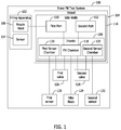
- FIG. 1 is a block diagram of an exemplary brake fill test system 100 .
- brake fill test system 100 includes a filling apparatus 102 and a vessel 104 in selective flow communication with filling apparatus 102 .
- Filling apparatus 102 includes a nozzle head 106 .
- vessel 104 includes an interior 108 , and a first port 110 and a second port 112 that provide access to interior 108 .
- First port 110 is oriented to channel fluid into interior 108 and second port 112 is oriented to discharge the fluid from interior 108 .
- selective flow communication is provided between filling apparatus 102 and vessel 104 when nozzle head 106 mates with first port 110 of vessel 104 .
- nozzle head 106 substantially seals first port 110 with an air tight interface when mated therewith.
- Second port 112 is also sealed with an air tight interface to facilitate sealing interior 108 when filling apparatus 102 performs a fluid filling operation.
- the fluid filling operation includes performance of a vacuum cycle followed by performance of a fill cycle.
- filling apparatus 102 may be any device that enables brake fill test system 100 to function as described herein.
- filling apparatus 102 is an automated or robotic device that is capable of performing both the vacuum cycle and the fill cycle.
- Filling apparatus 102 also includes a sensor 114 for use in monitoring either a positive gauge pressure or a negative gauge pressure applied to interior 108 of vessel 104 during the vacuum cycle and the fill cycle. In some embodiments, malfunctions in one or more components of filling apparatus 102 may result in sensor 114 providing inaccurate gauge pressure readings.
- vessel 104 includes a plurality of side walls 116 that define interior 108 , which includes a fill chamber 118 , a first sensor chamber 120 , and a second sensor chamber 122 .
- Fill chamber 118 is sized to simulate a known volume of a brake fluid system of a vehicle.
- fill chamber 118 has a fixed volume equal to about one liter, which may be oversized relative to a known volume of a brake fluid system of a vehicle.
- brake fill test system 100 further includes a filler block 124 that is selectively positionable within fill chamber 118 .
- Filler block 124 may have any size that enables vessel 104 to function as described herein and, in one embodiment, is sized to reduce the volume of fill chamber 118 by a predetermined amount.
- brake fluid systems in different vehicles may have different volumetric capacities, and the size of filler block 124 is selected to reduce the volume of fill chamber 118 to substantially match the different volumetric capacities.
- filler block 124 is sized for insertion through at least one of first port 110 or second port 112 .
- Brake fill test system 100 includes a first valve 126 positioned between fill chamber 118 and first sensor chamber 120 , and a second valve 128 positioned between fill chamber 118 and second sensor chamber 122 .
- First valve 126 is actuatable to provide selective flow communication between fill chamber 118 and first sensor chamber 120
- second valve 128 is actuatable to provide selective flow communication between fill chamber 118 and second sensor chamber 122 .
- first valve 126 and second valve 128 are each selectively operable to provide flow communication between fill chamber 118 and only one of first sensor chamber 120 or second sensor chamber 122 at a time.
- brake fill test system 100 further includes a first sensor 130 and a second sensor 132 .
- First sensor 130 is coupled within first sensor chamber 120
- second sensor 132 is coupled within second sensor chamber 122 .
- First sensor 130 monitors a positive gauge pressure within interior 108
- second sensor 132 monitors a negative gauge pressure within interior 108 .
- pressure readings from within interior 108 are obtained independent of those obtained by sensor 114 of filling apparatus 102
- filling apparatus 102 performs a fluid filling operation, which includes performance of a vacuum cycle followed by performance of a fill cycle.
- first valve 126 is actuated into a closed position to seal first sensor chamber 120 from fill chamber 118
- second valve 128 is actuated into an open position to provide flow communication between fill chamber 118 and second sensor chamber 122 .
- Filling apparatus 102 then performs the vacuum cycle to remove air from interior 108 as second sensor 132 monitors the negative gauge pressure within interior 108 .
- the gauge pressure value(s) obtained by second sensor 132 are recorded and compared to the gauge pressure value(s) obtained by sensor 114 of filling apparatus 102 . Differences in the gauge pressure value(s) may provide an indication that one or more components of filling apparatus 102 have malfunctioned.
- filling apparatus 102 removes the air from interior 108 and then holds first port 110 under seal for a predetermined duration before performing the fill cycle.
- Second sensor 132 continues to monitor the gauge pressure within interior 108 over the predetermined duration, and facilitates determining variations in the gauge pressure. Variations in the gauge pressure (e.g., a decrease in an absolute gauge pressure value) over the predetermined duration may also provide an indication that one or more components of filling apparatus 102 have malfunctioned.
- first valve 126 is actuated into an open position to provide flow communication between first sensor chamber 120 and fill chamber 118
- second valve 128 is actuated into a closed position to seal fill chamber 118 from second sensor chamber 122 .
- Filling apparatus 102 then performs the fill cycle to fill interior 108 with a predetermined volume of fluid, such as brake fluid, as first sensor 130 monitors the positive gauge pressure within interior 108 .
- the gauge pressure value(s) obtained by first sensor 130 are recorded and compared to the gauge pressure value(s) obtained by sensor 114 of filling apparatus 102 . Differences in the gauge pressure value(s) may provide an indication that one or more components of filling apparatus 102 have malfunctioned.
- side walls 116 of vessel 104 are capable of withstanding deformation when interior 108 is pressurized during the vacuum cycle and the fill cycle.
- the material used to fabricate the plurality of side walls 116 is selected to withstand deformation when an absolute gauge pressure value within interior 108 is less than a predetermined value.
- An example pressure range typically experienced during the filling cycle is defined within a range between about 0 pounds per square inch (psi) and about 100 psi
- an example range typically experienced during the vacuum cycle is defined within a range between about 0.05 Torr and about 20 Torr. Under normal working conditions the vacuum can reach as low as 0.12 Torr and the specification for fill pressure is 57 psi.
- side walls 116 withstand deformation to facilitate ensuring the accuracy of pressure readings obtained by first sensor 130 and second sensor 132 during the vacuum and fill cycles.
- solid lines, if any, connecting various elements and/or components may represent mechanical, electrical, fluid, optical, electromagnetic and other couplings and/or combinations thereof.
- dashed lines, if any, connecting the various elements and/or components represent couplings similar in function and purpose to those represented by solid lines; however, couplings represented by the dashed lines may either be selectively provided or may relate to alternative or optional examples of the present disclosure.
- FIGS. 2-4 are views of brake fill test system 100 .
- brake fill test system 100 includes an actuator 134 (e.g., an air pressure regulator) coupled to vessel 104 and in flow communication with first valve 126 and second valve 128 .
- Actuator 134 controls actuation of first valve 126 and second valve 128 pneumatically.
- actuator 134 controls actuation of first valve 126 and second valve 128 via any means, such as electrical or mechanical means, that enables brake fill test system 100 to function as described herein.
- first sensor 130 and second sensor 132 are removably coupleable from vessel 104 at first sensor chamber 120 and second sensor chamber 122 .
- second port 112 of vessel 104 is sealed by a cover 136 that is also removably coupleable from vessel 104 .
- First sensor 130 , second sensor 132 , and cover 136 are removably coupleable from vessel 104 with a vacuum flange 138 . Vacuum flanges 138 facilitate sealing openings in vessel 104 with an air tight interface.
- first port 110 is oriented to channel fluid into interior 108 (shown in FIG. 1 ) and second port 112 is oriented to discharge the fluid from interior 108 .
- first port 110 is positioned at a top portion 140 of vessel 104
- second port 112 is positioned at a bottom portion 142 of vessel 104 .
- fluid within in interior 108 is capable of being gravity drained through second port 112 .
- first port 110 is fitted with a flanged opening 144 , which enables first port 110 to mate with filling apparatus 102 (shown in FIG. 1 ) with a sealing engagement.
Landscapes
- Engineering & Computer Science (AREA)
- Transportation (AREA)
- Mechanical Engineering (AREA)
- Physics & Mathematics (AREA)
- General Physics & Mathematics (AREA)
- Valves And Accessory Devices For Braking Systems (AREA)
Abstract
Description
Claims (20)
Priority Applications (1)
| Application Number | Priority Date | Filing Date | Title |
|---|---|---|---|
| US16/048,717 US10656038B2 (en) | 2018-07-30 | 2018-07-30 | Apparatus, system, and method for use in fluid filling apparatus inspection |
Applications Claiming Priority (1)
| Application Number | Priority Date | Filing Date | Title |
|---|---|---|---|
| US16/048,717 US10656038B2 (en) | 2018-07-30 | 2018-07-30 | Apparatus, system, and method for use in fluid filling apparatus inspection |
Publications (2)
| Publication Number | Publication Date |
|---|---|
| US20200033213A1 US20200033213A1 (en) | 2020-01-30 |
| US10656038B2 true US10656038B2 (en) | 2020-05-19 |
Family
ID=69179122
Family Applications (1)
| Application Number | Title | Priority Date | Filing Date |
|---|---|---|---|
| US16/048,717 Active 2039-01-09 US10656038B2 (en) | 2018-07-30 | 2018-07-30 | Apparatus, system, and method for use in fluid filling apparatus inspection |
Country Status (1)
| Country | Link |
|---|---|
| US (1) | US10656038B2 (en) |
Families Citing this family (1)
| Publication number | Priority date | Publication date | Assignee | Title |
|---|---|---|---|---|
| CN113335259B (en) * | 2021-07-22 | 2022-06-21 | 中国第一汽车股份有限公司 | Brake system power-on detection method, device, equipment and storage medium |
Citations (60)
| Publication number | Priority date | Publication date | Assignee | Title |
|---|---|---|---|---|
| US1825013A (en) * | 1928-09-15 | 1931-09-29 | Mountain Chemical Company | Method and apparatus for flushing and filling hydraulic brake systems |
| US2295539A (en) * | 1940-04-11 | 1942-09-15 | Puritan Company | Apparatus for servicing hydraulic brakes |
| US2509570A (en) * | 1947-06-21 | 1950-05-30 | Lee William Warden | Device for supplying brake fluid |
| US3125879A (en) * | 1964-03-24 | Flow rate calibration | ||
| US3216622A (en) * | 1963-07-01 | 1965-11-09 | Drostholm Frede Hilmar | Method of controlling the quantities discharged during predetermined periods of one or more viscous liquids and apparatus for performing the method |
| US3339401A (en) * | 1965-04-01 | 1967-09-05 | Gen Motors Corp | Brake bleed and fill machine |
| US3425464A (en) * | 1967-01-17 | 1969-02-04 | Gen Motors Corp | Fluid filling method and apparatus |
| US3548978A (en) * | 1969-04-14 | 1970-12-22 | Elbert S Dyke | Hydraulic brake bleeding apparatus |
| US3638485A (en) * | 1969-06-05 | 1972-02-01 | Walter T Knauth | Apparatus for totalizing liquid volumes in a plurality of containers |
| US3696659A (en) * | 1971-08-25 | 1972-10-10 | Itt | Instrument pressure calibration method and apparatus |
| US3939688A (en) * | 1974-09-16 | 1976-02-24 | Edge Saw Manufacturing Company | Volumetric calibration |
| US4006762A (en) * | 1975-08-11 | 1977-02-08 | Textron, Inc. | Fuel tank level detector and shut-off valve |
| US4017329A (en) * | 1976-01-07 | 1977-04-12 | Larson Philip C | Method of restoring hydraulic systems |
| US4165819A (en) * | 1976-06-22 | 1979-08-28 | Joma-Maschinenbau Karl Jost | Mobile equipment for air-flushing, filling and venting a hydraulic brake system |
| US4415071A (en) * | 1981-07-27 | 1983-11-15 | Butler Eric S | Device for bleeding brakes and refilling brake system |
| US4509802A (en) * | 1981-09-18 | 1985-04-09 | Daimler-Benz Aktiengesellschaft | Installation for charging a pressure reservoir provided as a pressure source within a propulsion control system of a motor vehicle |
| US4708010A (en) * | 1984-10-17 | 1987-11-24 | The Foxboro Company | Apparatus and method for calibrating span of pressure measuring instruments |
| US4899574A (en) * | 1989-02-01 | 1990-02-13 | The Mead Corporation | Method and apparatus for detecting leaks in a sealed container |
| WO1990002083A1 (en) * | 1988-08-31 | 1990-03-08 | Arthur Koerner | Method and apparatus for filling hydraulic systems |
| US5060703A (en) * | 1988-08-31 | 1991-10-29 | Arthur Koerner | Apparatus for filling hydraulic systems |
| US5088529A (en) * | 1990-08-27 | 1992-02-18 | General Motors Corporation | Vehicle brake vacuum evacuation and brake fluid fill machine |
| US5361624A (en) | 1993-11-02 | 1994-11-08 | General Motors Corporation | Sensor for dissolved air in brake fluid and method of using the same |
| US5641003A (en) * | 1994-04-08 | 1997-06-24 | Societe Nationale Industrielle Et Aerospatiale | Process for the replacement of a hydraulic fluid contained in a control circuit such as an aircraft circuit |
| US5653316A (en) * | 1995-06-29 | 1997-08-05 | Kane; Michael J. | Hydraulic system bleeding |
| US5694808A (en) * | 1993-11-03 | 1997-12-09 | Itt Automotive Europe Gmbh | System for testing the function of a hydraulic device |
| US5767389A (en) * | 1995-07-26 | 1998-06-16 | Automotive Products (Usa), Inc. | Method and apparatus for testing a fluid pressure apparatus |
| US5787372A (en) * | 1994-04-25 | 1998-07-28 | Edwards; Robert W. | Automated fluid changing system with single-point connection |
| US5944068A (en) * | 1997-02-13 | 1999-08-31 | Kelsey-Hayes Company | Apparatus and method for prefilling secondary hydraulic circuits of a vehicular braking system |
| US5964326A (en) * | 1998-03-17 | 1999-10-12 | Lee; Kin Bong | Apparatus for bleeding and refilling hydraulic brake system |
| US6179392B1 (en) * | 1996-12-23 | 2001-01-30 | Continental Teves Ag & Co., Ohg | Method of eliminating the inclusion of gas bubbles when filling of brake fluid into a hydraulic automotive vehicle brake system |
| US6206055B1 (en) * | 1998-10-08 | 2001-03-27 | Peter C. Hollub | Apparatus and method for removing and replacing vehicle hydraulic fluid |
| US6302167B1 (en) * | 2000-01-13 | 2001-10-16 | Peter C. Hollub | Apparatus and method for removing and replacing vehicular hydraulic fluid while flushing the hydraulic system |
| US6443192B1 (en) | 2001-08-22 | 2002-09-03 | Harold E. Erwin | Vehicle brake flush method and apparatus |
| US6530264B1 (en) * | 2000-11-16 | 2003-03-11 | Autoliv Asp, Inc. | Detection systems and methods |
| US20040089371A1 (en) * | 2001-10-29 | 2004-05-13 | Few Jeffery P. | Fluid servicing apparatus with dielectric sensing control system |
| US20040123641A1 (en) * | 2001-03-02 | 2004-07-01 | Rene Gilbert | Method and device for controlling a sensor |
| US20040173005A1 (en) * | 2003-03-07 | 2004-09-09 | Martone Christopher James | Self-contained portable air pressure decay test apparatus |
| US6796339B1 (en) * | 2003-07-03 | 2004-09-28 | Phoenix Systems, L.L.C. | Apparatus for flushing, replacing fluid and bleeding hydraulic systems |
| US6929036B2 (en) * | 2003-09-17 | 2005-08-16 | Adam Awad | Automotive fluid exchange system and method of use |
| US7152636B2 (en) * | 2003-11-04 | 2006-12-26 | Phoenix Systems, L.L.C. | Brake flush accelerator |
| DE102005052640B3 (en) | 2005-11-04 | 2007-02-22 | Hydac Electronic Gmbh | Method for on line monitoring of pre-fill pressure of hydraulic accumulator, involves determination of difference volume, pressure values and pre-fill pressure which is calculated during fluid withdrawal of accumulator volume |
| US20070210646A1 (en) * | 2006-02-17 | 2007-09-13 | Magneti Marelli Powertrain S. P. A. | Method and plant for filling a hydraulic circuit with a control fluid |
| US20070289827A1 (en) * | 2004-06-16 | 2007-12-20 | Toyota Jidosha Kabushiki Kaisha | Master Cylinder With Fill-Up Function |
| US20080060421A1 (en) * | 2006-09-07 | 2008-03-13 | Matheson Tri-Gas | Leak characterization apparatuses and methods for fluid storage containers |
| US20080307858A1 (en) * | 2005-02-28 | 2008-12-18 | Advanced Technology Materials, Inc. | Apparatus and Process for Leak-Testing and Qualification of Fluid Dispensing Vessels |
| CN201207007Y (en) * | 2008-05-13 | 2009-03-11 | 奇瑞汽车股份有限公司 | Calibration device for brake fluid charging machine |
| US20110253252A1 (en) * | 2008-11-04 | 2011-10-20 | American Grease Stick Company | Brake bleeding apparatus |
| US8215343B2 (en) * | 2007-08-01 | 2012-07-10 | Rti Technologies, Inc. | Automotive service equipment and method for brake fluid exchange with wireless brake bleeding system |
| US20120247615A1 (en) * | 2011-03-30 | 2012-10-04 | Honda Motor Co., Ltd. | Brake fill tool |
| US8464763B2 (en) * | 2005-11-03 | 2013-06-18 | Phoenix Systems, L.L.C. | Brake flush machine |
| US8955561B2 (en) * | 2011-10-04 | 2015-02-17 | Spillx Llc | Refilling apparatus with jet level sensor |
| US20150226628A1 (en) * | 2012-10-23 | 2015-08-13 | Sartorius Stedim Biotech Gmbh | Method and device for verification and/or calibration of a pressure sensor |
| US9260988B2 (en) * | 2013-09-12 | 2016-02-16 | Euroiltec Industry Co., Ltd. | Self-help oil changing apparatus |
| US20170102015A1 (en) * | 2015-10-12 | 2017-04-13 | GM Global Technology Operations LLC | Fluid testing device, and a method of testing a pressurized fluid for dissolved and/or entrained gasses |
| US20170167939A1 (en) * | 2015-12-15 | 2017-06-15 | Honeywell International, Inc. | Pressure sensor drift detection and correction |
| US20180010599A1 (en) * | 2015-01-29 | 2018-01-11 | Hewlett-Packard Development Company, L.P. | Calibration of a pump |
| US20180017460A1 (en) * | 2015-01-24 | 2018-01-18 | Setra Systems, Inc. | A system and method for callibrating and controlling pressure |
| CN209602076U (en) * | 2019-03-15 | 2019-11-08 | 东风小康汽车有限公司重庆分公司 | Calibration device for vehicle brake fluid tank and coolant tank |
| US20200009311A1 (en) * | 2018-07-03 | 2020-01-09 | Baxter International Inc. | Disposable cassette conditioning system and method |
| US20200031328A1 (en) * | 2018-07-30 | 2020-01-30 | Honda Motor Co., Ltd. | Apparatus, system, and method for use in brake caliper inspection |
-
2018
- 2018-07-30 US US16/048,717 patent/US10656038B2/en active Active
Patent Citations (61)
| Publication number | Priority date | Publication date | Assignee | Title |
|---|---|---|---|---|
| US3125879A (en) * | 1964-03-24 | Flow rate calibration | ||
| US1825013A (en) * | 1928-09-15 | 1931-09-29 | Mountain Chemical Company | Method and apparatus for flushing and filling hydraulic brake systems |
| US2295539A (en) * | 1940-04-11 | 1942-09-15 | Puritan Company | Apparatus for servicing hydraulic brakes |
| US2509570A (en) * | 1947-06-21 | 1950-05-30 | Lee William Warden | Device for supplying brake fluid |
| US3216622A (en) * | 1963-07-01 | 1965-11-09 | Drostholm Frede Hilmar | Method of controlling the quantities discharged during predetermined periods of one or more viscous liquids and apparatus for performing the method |
| US3339401A (en) * | 1965-04-01 | 1967-09-05 | Gen Motors Corp | Brake bleed and fill machine |
| US3425464A (en) * | 1967-01-17 | 1969-02-04 | Gen Motors Corp | Fluid filling method and apparatus |
| US3548978A (en) * | 1969-04-14 | 1970-12-22 | Elbert S Dyke | Hydraulic brake bleeding apparatus |
| US3638485A (en) * | 1969-06-05 | 1972-02-01 | Walter T Knauth | Apparatus for totalizing liquid volumes in a plurality of containers |
| US3696659A (en) * | 1971-08-25 | 1972-10-10 | Itt | Instrument pressure calibration method and apparatus |
| US3939688A (en) * | 1974-09-16 | 1976-02-24 | Edge Saw Manufacturing Company | Volumetric calibration |
| US4006762A (en) * | 1975-08-11 | 1977-02-08 | Textron, Inc. | Fuel tank level detector and shut-off valve |
| US4017329A (en) * | 1976-01-07 | 1977-04-12 | Larson Philip C | Method of restoring hydraulic systems |
| US4165819A (en) * | 1976-06-22 | 1979-08-28 | Joma-Maschinenbau Karl Jost | Mobile equipment for air-flushing, filling and venting a hydraulic brake system |
| US4415071A (en) * | 1981-07-27 | 1983-11-15 | Butler Eric S | Device for bleeding brakes and refilling brake system |
| US4509802A (en) * | 1981-09-18 | 1985-04-09 | Daimler-Benz Aktiengesellschaft | Installation for charging a pressure reservoir provided as a pressure source within a propulsion control system of a motor vehicle |
| US4708010A (en) * | 1984-10-17 | 1987-11-24 | The Foxboro Company | Apparatus and method for calibrating span of pressure measuring instruments |
| WO1990002083A1 (en) * | 1988-08-31 | 1990-03-08 | Arthur Koerner | Method and apparatus for filling hydraulic systems |
| US5060703A (en) * | 1988-08-31 | 1991-10-29 | Arthur Koerner | Apparatus for filling hydraulic systems |
| US4899574A (en) * | 1989-02-01 | 1990-02-13 | The Mead Corporation | Method and apparatus for detecting leaks in a sealed container |
| US5088529A (en) * | 1990-08-27 | 1992-02-18 | General Motors Corporation | Vehicle brake vacuum evacuation and brake fluid fill machine |
| US5361624A (en) | 1993-11-02 | 1994-11-08 | General Motors Corporation | Sensor for dissolved air in brake fluid and method of using the same |
| US5694808A (en) * | 1993-11-03 | 1997-12-09 | Itt Automotive Europe Gmbh | System for testing the function of a hydraulic device |
| US5641003A (en) * | 1994-04-08 | 1997-06-24 | Societe Nationale Industrielle Et Aerospatiale | Process for the replacement of a hydraulic fluid contained in a control circuit such as an aircraft circuit |
| US5787372A (en) * | 1994-04-25 | 1998-07-28 | Edwards; Robert W. | Automated fluid changing system with single-point connection |
| US5653316A (en) * | 1995-06-29 | 1997-08-05 | Kane; Michael J. | Hydraulic system bleeding |
| US5767389A (en) * | 1995-07-26 | 1998-06-16 | Automotive Products (Usa), Inc. | Method and apparatus for testing a fluid pressure apparatus |
| US6179392B1 (en) * | 1996-12-23 | 2001-01-30 | Continental Teves Ag & Co., Ohg | Method of eliminating the inclusion of gas bubbles when filling of brake fluid into a hydraulic automotive vehicle brake system |
| US5944068A (en) * | 1997-02-13 | 1999-08-31 | Kelsey-Hayes Company | Apparatus and method for prefilling secondary hydraulic circuits of a vehicular braking system |
| US5964326A (en) * | 1998-03-17 | 1999-10-12 | Lee; Kin Bong | Apparatus for bleeding and refilling hydraulic brake system |
| US6206055B1 (en) * | 1998-10-08 | 2001-03-27 | Peter C. Hollub | Apparatus and method for removing and replacing vehicle hydraulic fluid |
| US6302167B1 (en) * | 2000-01-13 | 2001-10-16 | Peter C. Hollub | Apparatus and method for removing and replacing vehicular hydraulic fluid while flushing the hydraulic system |
| US6530264B1 (en) * | 2000-11-16 | 2003-03-11 | Autoliv Asp, Inc. | Detection systems and methods |
| US20040123641A1 (en) * | 2001-03-02 | 2004-07-01 | Rene Gilbert | Method and device for controlling a sensor |
| US6443192B1 (en) | 2001-08-22 | 2002-09-03 | Harold E. Erwin | Vehicle brake flush method and apparatus |
| US20030037837A1 (en) * | 2001-08-22 | 2003-02-27 | Erwin Harold E. | Brake flush method |
| US20040089371A1 (en) * | 2001-10-29 | 2004-05-13 | Few Jeffery P. | Fluid servicing apparatus with dielectric sensing control system |
| US20040173005A1 (en) * | 2003-03-07 | 2004-09-09 | Martone Christopher James | Self-contained portable air pressure decay test apparatus |
| US6796339B1 (en) * | 2003-07-03 | 2004-09-28 | Phoenix Systems, L.L.C. | Apparatus for flushing, replacing fluid and bleeding hydraulic systems |
| US6929036B2 (en) * | 2003-09-17 | 2005-08-16 | Adam Awad | Automotive fluid exchange system and method of use |
| US7152636B2 (en) * | 2003-11-04 | 2006-12-26 | Phoenix Systems, L.L.C. | Brake flush accelerator |
| US20070289827A1 (en) * | 2004-06-16 | 2007-12-20 | Toyota Jidosha Kabushiki Kaisha | Master Cylinder With Fill-Up Function |
| US20080307858A1 (en) * | 2005-02-28 | 2008-12-18 | Advanced Technology Materials, Inc. | Apparatus and Process for Leak-Testing and Qualification of Fluid Dispensing Vessels |
| US8464763B2 (en) * | 2005-11-03 | 2013-06-18 | Phoenix Systems, L.L.C. | Brake flush machine |
| DE102005052640B3 (en) | 2005-11-04 | 2007-02-22 | Hydac Electronic Gmbh | Method for on line monitoring of pre-fill pressure of hydraulic accumulator, involves determination of difference volume, pressure values and pre-fill pressure which is calculated during fluid withdrawal of accumulator volume |
| US20070210646A1 (en) * | 2006-02-17 | 2007-09-13 | Magneti Marelli Powertrain S. P. A. | Method and plant for filling a hydraulic circuit with a control fluid |
| US20080060421A1 (en) * | 2006-09-07 | 2008-03-13 | Matheson Tri-Gas | Leak characterization apparatuses and methods for fluid storage containers |
| US8215343B2 (en) * | 2007-08-01 | 2012-07-10 | Rti Technologies, Inc. | Automotive service equipment and method for brake fluid exchange with wireless brake bleeding system |
| CN201207007Y (en) * | 2008-05-13 | 2009-03-11 | 奇瑞汽车股份有限公司 | Calibration device for brake fluid charging machine |
| US20110253252A1 (en) * | 2008-11-04 | 2011-10-20 | American Grease Stick Company | Brake bleeding apparatus |
| US20120247615A1 (en) * | 2011-03-30 | 2012-10-04 | Honda Motor Co., Ltd. | Brake fill tool |
| US8955561B2 (en) * | 2011-10-04 | 2015-02-17 | Spillx Llc | Refilling apparatus with jet level sensor |
| US20150226628A1 (en) * | 2012-10-23 | 2015-08-13 | Sartorius Stedim Biotech Gmbh | Method and device for verification and/or calibration of a pressure sensor |
| US9260988B2 (en) * | 2013-09-12 | 2016-02-16 | Euroiltec Industry Co., Ltd. | Self-help oil changing apparatus |
| US20180017460A1 (en) * | 2015-01-24 | 2018-01-18 | Setra Systems, Inc. | A system and method for callibrating and controlling pressure |
| US20180010599A1 (en) * | 2015-01-29 | 2018-01-11 | Hewlett-Packard Development Company, L.P. | Calibration of a pump |
| US20170102015A1 (en) * | 2015-10-12 | 2017-04-13 | GM Global Technology Operations LLC | Fluid testing device, and a method of testing a pressurized fluid for dissolved and/or entrained gasses |
| US20170167939A1 (en) * | 2015-12-15 | 2017-06-15 | Honeywell International, Inc. | Pressure sensor drift detection and correction |
| US20200009311A1 (en) * | 2018-07-03 | 2020-01-09 | Baxter International Inc. | Disposable cassette conditioning system and method |
| US20200031328A1 (en) * | 2018-07-30 | 2020-01-30 | Honda Motor Co., Ltd. | Apparatus, system, and method for use in brake caliper inspection |
| CN209602076U (en) * | 2019-03-15 | 2019-11-08 | 东风小康汽车有限公司重庆分公司 | Calibration device for vehicle brake fluid tank and coolant tank |
Non-Patent Citations (2)
| Title |
|---|
| English Translation of CN 201207007 (2009). * |
| English Translation of CN 209602076 (2019). * |
Also Published As
| Publication number | Publication date |
|---|---|
| US20200033213A1 (en) | 2020-01-30 |
Similar Documents
| Publication | Publication Date | Title |
|---|---|---|
| CN103837311B (en) | A kind of characterization processes method and device of Multicarity valve inner seepage | |
| CN112840192B (en) | Testing method for testing cable tightness and tightness testing device for performing the method | |
| EP3754235B1 (en) | A method and device for in-situ testing a vacuum-pressure valve of a storage tank | |
| WO2013102610A1 (en) | Method for detecting a leak on a non-rigid test specimen | |
| EP3470811B1 (en) | Device and method for testing integrity of glove and glove port of an isolator | |
| CN105003713B (en) | A kind of ball valve sealing end cap | |
| RU2670675C1 (en) | Tests stand for pipeline fittings, its elements and couplers for strength and trim impermeability | |
| US10656038B2 (en) | Apparatus, system, and method for use in fluid filling apparatus inspection | |
| US11021143B2 (en) | Apparatus, system, and method for use in brake caliper inspection | |
| US3727453A (en) | Apparatus for testing air brake control valves | |
| CN112179583A (en) | Bogie brake pipe air tightness automatic test device | |
| CN109520676A (en) | A kind of cylinder head air tight test device and its control system and operating method | |
| US9709081B2 (en) | Fluid testing device, and a method of testing a pressurized fluid for dissolved and/or entrained gasses | |
| JP5108852B2 (en) | Vacuum pump inspection method and vacuum pressure measuring device | |
| US12013314B2 (en) | Method for leak testing a tank head before it enters service | |
| CN118883405A (en) | Test method and test system for measuring hydrogen absorption expansion rate of non-metallic parts | |
| KR100912068B1 (en) | Air test method for airtightness and airtight closure | |
| JPH07239284A (en) | Leak inspection device | |
| RU2623188C1 (en) | Method of inspection of product sealing and device for implementation of the method | |
| EP2924412B1 (en) | Apparatus and method for testing the seal of explosion-proof boxes. | |
| US10626006B2 (en) | Fluid fill tool and methods of using the same | |
| US5540084A (en) | Vacuum system testing tool | |
| US20170313157A1 (en) | Method for changing coolant in a vehicle engine | |
| CN205714711U (en) | A kind of air compressor machine dispatches from the factory performance test bed | |
| CN120869498B (en) | Online inspection fixtures for breather valves, breather valves capable of online inspection, methods for testing the sealing performance of breather valves, and online inspection methods for breather valves. |
Legal Events
| Date | Code | Title | Description |
|---|---|---|---|
| AS | Assignment |
Owner name: HONDA MOTOR CO., LTD., JAPAN Free format text: ASSIGNMENT OF ASSIGNORS INTEREST;ASSIGNORS:HILL, ROBERT LEE;REEVES, JAMES ALLEN;REEL/FRAME:046499/0542 Effective date: 20180727 |
|
| FEPP | Fee payment procedure |
Free format text: ENTITY STATUS SET TO UNDISCOUNTED (ORIGINAL EVENT CODE: BIG.); ENTITY STATUS OF PATENT OWNER: LARGE ENTITY |
|
| STPP | Information on status: patent application and granting procedure in general |
Free format text: PUBLICATIONS -- ISSUE FEE PAYMENT VERIFIED |
|
| STCF | Information on status: patent grant |
Free format text: PATENTED CASE |
|
| MAFP | Maintenance fee payment |
Free format text: PAYMENT OF MAINTENANCE FEE, 4TH YEAR, LARGE ENTITY (ORIGINAL EVENT CODE: M1551); ENTITY STATUS OF PATENT OWNER: LARGE ENTITY Year of fee payment: 4 |