US10655067B2 - Device for regulating the entry of light - Google Patents
Device for regulating the entry of light Download PDFInfo
- Publication number
- US10655067B2 US10655067B2 US16/068,207 US201616068207A US10655067B2 US 10655067 B2 US10655067 B2 US 10655067B2 US 201616068207 A US201616068207 A US 201616068207A US 10655067 B2 US10655067 B2 US 10655067B2
- Authority
- US
- United States
- Prior art keywords
- layer
- liquid
- crystalline medium
- orientation
- molecules
- Prior art date
- Legal status (The legal status is an assumption and is not a legal conclusion. Google has not performed a legal analysis and makes no representation as to the accuracy of the status listed.)
- Active
Links
- 230000001105 regulatory effect Effects 0.000 title claims abstract description 10
- 150000001875 compounds Chemical class 0.000 claims abstract description 70
- 230000003287 optical effect Effects 0.000 claims description 16
- 230000000694 effects Effects 0.000 claims description 10
- 239000004642 Polyimide Substances 0.000 claims description 6
- 229920001721 polyimide Polymers 0.000 claims description 6
- FNQJDLTXOVEEFB-UHFFFAOYSA-N 1,2,3-benzothiadiazole Chemical class C1=CC=C2SN=NC2=C1 FNQJDLTXOVEEFB-UHFFFAOYSA-N 0.000 claims description 4
- 238000006243 chemical reaction Methods 0.000 claims description 4
- 229930192627 Naphthoquinone Natural products 0.000 claims description 3
- 238000000034 method Methods 0.000 claims description 3
- 150000002791 naphthoquinones Chemical class 0.000 claims description 3
- 150000002979 perylenes Chemical class 0.000 claims description 3
- 150000004056 anthraquinones Chemical class 0.000 claims description 2
- 125000000751 azo group Chemical group [*]N=N[*] 0.000 claims description 2
- DZVCFNFOPIZQKX-LTHRDKTGSA-M merocyanine Chemical class [Na+].O=C1N(CCCC)C(=O)N(CCCC)C(=O)C1=C\C=C\C=C/1N(CCCS([O-])(=O)=O)C2=CC=CC=C2O\1 DZVCFNFOPIZQKX-LTHRDKTGSA-M 0.000 claims description 2
- 125000001434 methanylylidene group Chemical group [H]C#[*] 0.000 claims description 2
- 150000004905 tetrazines Chemical class 0.000 claims description 2
- 229920004933 Terylene® Polymers 0.000 claims 1
- 239000010410 layer Substances 0.000 description 177
- 239000011521 glass Substances 0.000 description 32
- 239000000203 mixture Substances 0.000 description 28
- 239000000758 substrate Substances 0.000 description 17
- 230000005540 biological transmission Effects 0.000 description 14
- 230000000052 comparative effect Effects 0.000 description 14
- 238000002834 transmittance Methods 0.000 description 12
- 230000007547 defect Effects 0.000 description 9
- 239000002019 doping agent Substances 0.000 description 9
- 239000000975 dye Substances 0.000 description 9
- 238000004519 manufacturing process Methods 0.000 description 8
- 238000010521 absorption reaction Methods 0.000 description 7
- 229920000642 polymer Polymers 0.000 description 7
- 230000008859 change Effects 0.000 description 6
- 239000010408 film Substances 0.000 description 6
- 230000003595 spectral effect Effects 0.000 description 6
- 0 *c(cc1)ccc1C#Cc(c1n[s]nc11)ccc1C#Cc1ccc(*)cc1 Chemical compound *c(cc1)ccc1C#Cc(c1n[s]nc11)ccc1C#Cc1ccc(*)cc1 0.000 description 5
- 239000012905 visible particle Substances 0.000 description 5
- 230000006872 improvement Effects 0.000 description 4
- 239000004973 liquid crystal related substance Substances 0.000 description 4
- 239000000463 material Substances 0.000 description 4
- 230000005281 excited state Effects 0.000 description 3
- 230000000704 physical effect Effects 0.000 description 3
- 230000005855 radiation Effects 0.000 description 3
- 230000007704 transition Effects 0.000 description 3
- 125000004955 1,4-cyclohexylene group Chemical group [H]C1([H])C([H])([H])C([H])([*:1])C([H])([H])C([H])([H])C1([H])[*:2] 0.000 description 2
- 125000001140 1,4-phenylene group Chemical group [H]C1=C([H])C([*:2])=C([H])C([H])=C1[*:1] 0.000 description 2
- DNZASWNTGKYDSP-UHFFFAOYSA-N 4-(4-butylcyclohexyl)-1-heptylcyclohexane-1-carbonitrile Chemical compound C1CC(CCCCCCC)(C#N)CCC1C1CCC(CCCC)CC1 DNZASWNTGKYDSP-UHFFFAOYSA-N 0.000 description 2
- 239000005964 Acibenzolar-S-methyl Substances 0.000 description 2
- HOYVQNRGOQDDOB-UHFFFAOYSA-N C=C(C)C(=O)OCCC1=CC=C(C2=CC=C(C3=CC=C(C4=CC=C(C5=CC=C(OC)C=C5)S4)C4=NSN=C34)S2)C=C1 Chemical compound C=C(C)C(=O)OCCC1=CC=C(C2=CC=C(C3=CC=C(C4=CC=C(C5=CC=C(OC)C=C5)S4)C4=NSN=C34)S2)C=C1 HOYVQNRGOQDDOB-UHFFFAOYSA-N 0.000 description 2
- QQPMUQQIBYFTHT-UHFFFAOYSA-N CCCCCCC(C)OC(=O)c1ccc(OC(=O)c2ccc(C)cc2)cc1 Chemical compound CCCCCCC(C)OC(=O)c1ccc(OC(=O)c2ccc(C)cc2)cc1 QQPMUQQIBYFTHT-UHFFFAOYSA-N 0.000 description 2
- 239000002250 absorbent Substances 0.000 description 2
- 239000000987 azo dye Substances 0.000 description 2
- 238000000576 coating method Methods 0.000 description 2
- 239000012141 concentrate Substances 0.000 description 2
- 230000001419 dependent effect Effects 0.000 description 2
- 238000000151 deposition Methods 0.000 description 2
- 230000008021 deposition Effects 0.000 description 2
- 238000009826 distribution Methods 0.000 description 2
- 230000005283 ground state Effects 0.000 description 2
- 238000005259 measurement Methods 0.000 description 2
- 239000004984 smart glass Substances 0.000 description 2
- 239000003381 stabilizer Substances 0.000 description 2
- HSIYJXALRPGFOA-UHFFFAOYSA-N CC#CC(F)(F)C(F)(F)C1=CC=C(C2=CC=C(C3=CC=C(C4=CC=C(C5=C(F)C=C(C(F)(F)C(F)(F)C#CC)C=C5)S4)C4=NSN=C34)S2)C(F)=C1.[HH].[HH].[HH].[HH].[HH].[HH] Chemical compound CC#CC(F)(F)C(F)(F)C1=CC=C(C2=CC=C(C3=CC=C(C4=CC=C(C5=C(F)C=C(C(F)(F)C(F)(F)C#CC)C=C5)S4)C4=NSN=C34)S2)C(F)=C1.[HH].[HH].[HH].[HH].[HH].[HH] HSIYJXALRPGFOA-UHFFFAOYSA-N 0.000 description 1
- TVHGJFFIQOZTEG-UHFFFAOYSA-N CC#CCOC1=CC2=C(C=C1)C1=CC=C(C3=CC=C(C4=CC5=C(C=C4)C4=C(C=C(OCCCC)C=C4)C5(CCCCCCCC)CCCCCCCC)C4=NSN=C34)C=C1C2(CCCCCCCC)CCCCCCCC Chemical compound CC#CCOC1=CC2=C(C=C1)C1=CC=C(C3=CC=C(C4=CC5=C(C=C4)C4=C(C=C(OCCCC)C=C4)C5(CCCCCCCC)CCCCCCCC)C4=NSN=C34)C=C1C2(CCCCCCCC)CCCCCCCC TVHGJFFIQOZTEG-UHFFFAOYSA-N 0.000 description 1
- FTRKRHPCLABQGD-UHFFFAOYSA-N CC#CCOC1=CC=C2C=C(C3=CC(F)=C(C4=CC=C(C5=CC=C(C6=CC=C7C=C(OCCCC)C=CC7=C6)C=C5F)C5=NSN=C45)C=C3)C=CC2=C1 Chemical compound CC#CCOC1=CC=C2C=C(C3=CC(F)=C(C4=CC=C(C5=CC=C(C6=CC=C7C=C(OCCCC)C=CC7=C6)C=C5F)C5=NSN=C45)C=C3)C=CC2=C1 FTRKRHPCLABQGD-UHFFFAOYSA-N 0.000 description 1
- ZZSIDSMUTXFKNS-UHFFFAOYSA-N CC(C)C1=CC=CC(C(C)C)=C1N1C(=O)C2=C3C4=C(/C5=C(OC6=CC=CC=C6)/C=C6/C(=O)N(C7=C(C(C)C)C=CC=C7C(C)C)C(=O)C7=CC(OC8=CC=CC=C8)=C(C5=C76)/C4=C(OC4=CC=CC=C4)/C=C\3C1=O)/C(OC1=CC=CC=C1)=C\2 Chemical compound CC(C)C1=CC=CC(C(C)C)=C1N1C(=O)C2=C3C4=C(/C5=C(OC6=CC=CC=C6)/C=C6/C(=O)N(C7=C(C(C)C)C=CC=C7C(C)C)C(=O)C7=CC(OC8=CC=CC=C8)=C(C5=C76)/C4=C(OC4=CC=CC=C4)/C=C\3C1=O)/C(OC1=CC=CC=C1)=C\2 ZZSIDSMUTXFKNS-UHFFFAOYSA-N 0.000 description 1
- VDHPAAVFIDTPOM-UHFFFAOYSA-N CC1=C2C(C)C(C(C)(C)C)=C(C)N2B(F)(F)N2=C1C(C)=C(C(C)(C)C)C2C Chemical compound CC1=C2C(C)C(C(C)(C)C)=C(C)N2B(F)(F)N2=C1C(C)=C(C(C)(C)C)C2C VDHPAAVFIDTPOM-UHFFFAOYSA-N 0.000 description 1
- FVACZQWPYBQHHC-UHFFFAOYSA-N CC1CCC(C2CCC(C#N)(C3CCC(C)CC3)CC2)CC1.CC1CCC(C2CCC(C)(C#N)CC2)CC1 Chemical compound CC1CCC(C2CCC(C#N)(C3CCC(C)CC3)CC2)CC1.CC1CCC(C2CCC(C)(C#N)CC2)CC1 FVACZQWPYBQHHC-UHFFFAOYSA-N 0.000 description 1
- MAHFEVIBSGTLHC-UHFFFAOYSA-N CCC(C)C(O)c1ccc(-c2ccc(C#N)cc2)cc1 Chemical compound CCC(C)C(O)c1ccc(-c2ccc(C#N)cc2)cc1 MAHFEVIBSGTLHC-UHFFFAOYSA-N 0.000 description 1
- DNJQGRFZQMOYGM-UHFFFAOYSA-N CCC(C)Cc1ccc(-c2ccc(C#N)cc2)cc1 Chemical compound CCC(C)Cc1ccc(-c2ccc(C#N)cc2)cc1 DNJQGRFZQMOYGM-UHFFFAOYSA-N 0.000 description 1
- TZDDFSUEOGSUIP-UHFFFAOYSA-N CCC(C)OC(=O)C1=CC=C2C3=CC=C/C4=C(C(=O)OC(C)CC)/C=C\C(=C34)C3=C2/C1=C\C=C/3 Chemical compound CCC(C)OC(=O)C1=CC=C2C3=CC=C/C4=C(C(=O)OC(C)CC)/C=C\C(=C34)C3=C2/C1=C\C=C/3 TZDDFSUEOGSUIP-UHFFFAOYSA-N 0.000 description 1
- CCMYETBLCKZIFH-UHFFFAOYSA-N CCC(OC(=O)c1ccc(-c2ccc(C)cc2)cc1)c1ccccc1 Chemical compound CCC(OC(=O)c1ccc(-c2ccc(C)cc2)cc1)c1ccccc1 CCMYETBLCKZIFH-UHFFFAOYSA-N 0.000 description 1
- LNPHVNIYPYNRNM-UHFFFAOYSA-N CCCC(F)(F)C(F)(F)C1=CC=C(C2=CC=C(C3=NC=C(C4=CC=C(C5=C(F)C=C(C)C=C5)C=C4)C4=NSN=C34)C=C2)C(F)=C1 Chemical compound CCCC(F)(F)C(F)(F)C1=CC=C(C2=CC=C(C3=NC=C(C4=CC=C(C5=C(F)C=C(C)C=C5)C=C4)C4=NSN=C34)C=C2)C(F)=C1 LNPHVNIYPYNRNM-UHFFFAOYSA-N 0.000 description 1
- FMZCULCONCGHRL-UHFFFAOYSA-N CCCC(F)(F)OC1=CC=C(C2=CC=C(C3=CC=C(C4=CC=C(C5=C(F)C=C(OC(F)(F)CCC)C=C5)S4)C4=NSN=C34)S2)C(F)=C1 Chemical compound CCCC(F)(F)OC1=CC=C(C2=CC=C(C3=CC=C(C4=CC=C(C5=C(F)C=C(OC(F)(F)CCC)C=C5)S4)C4=NSN=C34)S2)C(F)=C1 FMZCULCONCGHRL-UHFFFAOYSA-N 0.000 description 1
- VVFAHTZZQZJHKA-UHFFFAOYSA-N CCCC(F)(F)OC1=CC=C(C2=CC=C(C3=CC=C(C4=CC=C(C5=CC=C(OC(F)(F)CCC)C=C5)S4)C4=NSN=C34)S2)C=C1 Chemical compound CCCC(F)(F)OC1=CC=C(C2=CC=C(C3=CC=C(C4=CC=C(C5=CC=C(OC(F)(F)CCC)C=C5)S4)C4=NSN=C34)S2)C=C1 VVFAHTZZQZJHKA-UHFFFAOYSA-N 0.000 description 1
- OZRUFPXCOGYMRM-UHFFFAOYSA-N CCCC(F)(F)OC1=CC=C2C=C(C3=CC=C(C4=CC=C5C=C(OC(F)(F)CCC)C=CC5=C4)C4=NSN=C34)C=CC2=C1 Chemical compound CCCC(F)(F)OC1=CC=C2C=C(C3=CC=C(C4=CC=C5C=C(OC(F)(F)CCC)C=CC5=C4)C4=NSN=C34)C=CC2=C1 OZRUFPXCOGYMRM-UHFFFAOYSA-N 0.000 description 1
- GDNLJVCOPVUMPN-UHFFFAOYSA-N CCCCC(CC)CCC1=CC=C(C2=CC=C(C3=C4C(=O)N(CC(CC)CCCC)C(C5=CC=C(C6=CC=C(CCC(CC)CCCC)C=C6)S5)=C4C(=O)N3CC(CC)CCCC)S2)C=C1 Chemical compound CCCCC(CC)CCC1=CC=C(C2=CC=C(C3=C4C(=O)N(CC(CC)CCCC)C(C5=CC=C(C6=CC=C(CCC(CC)CCCC)C=C6)S5)=C4C(=O)N3CC(CC)CCCC)S2)C=C1 GDNLJVCOPVUMPN-UHFFFAOYSA-N 0.000 description 1
- ZUNMHUZIBGQNQM-UHFFFAOYSA-N CCCCC(CC)CN1C(=O)C2=C(C3=CC4=C(C=C3)C3=C(C=C(C)C=C3)C4(C)C)N(CC(CC)CCCC)C(=O)C2=C1C1=CC=C2C(=C1)C(C)(C)C1=C2C=CC(C)=C1 Chemical compound CCCCC(CC)CN1C(=O)C2=C(C3=CC4=C(C=C3)C3=C(C=C(C)C=C3)C4(C)C)N(CC(CC)CCCC)C(=O)C2=C1C1=CC=C2C(=C1)C(C)(C)C1=C2C=CC(C)=C1 ZUNMHUZIBGQNQM-UHFFFAOYSA-N 0.000 description 1
- OVUKJNBYYLMWAQ-UHFFFAOYSA-N CCCCC(CC)COC1=CC=C(C2=CC=C(C3=C(F)C(F)=C(C4=CC=C(C5=CC=C(OCC(CC)CCCC)C=C5)S4)C4=NSN=C43)S2)C=C1 Chemical compound CCCCC(CC)COC1=CC=C(C2=CC=C(C3=C(F)C(F)=C(C4=CC=C(C5=CC=C(OCC(CC)CCCC)C=C5)S4)C4=NSN=C43)S2)C=C1 OVUKJNBYYLMWAQ-UHFFFAOYSA-N 0.000 description 1
- GPOYXIINRNIBMS-UHFFFAOYSA-N CCCCC(CC)COC1=CC=C(C2=CC=C(C3=C4C(=O)N(CC(CC)CCCC)C(C5=CC=C(C6=CC=C(OCC(CC)CCCC)C=C6)S5)=C4C(=O)N3CC(CC)CCCC)S2)C=C1 Chemical compound CCCCC(CC)COC1=CC=C(C2=CC=C(C3=C4C(=O)N(CC(CC)CCCC)C(C5=CC=C(C6=CC=C(OCC(CC)CCCC)C=C6)S5)=C4C(=O)N3CC(CC)CCCC)S2)C=C1 GPOYXIINRNIBMS-UHFFFAOYSA-N 0.000 description 1
- JTIOCBMJWFVNLG-UHFFFAOYSA-N CCCCC(CC)COC1=CC=C(C2=CC=C(C3=CC(F)=C(C4=CC=C(C5=CC=C(OCC(CC)CCCC)C=C5)S4)C4=NSN=C34)S2)C=C1 Chemical compound CCCCC(CC)COC1=CC=C(C2=CC=C(C3=CC(F)=C(C4=CC=C(C5=CC=C(OCC(CC)CCCC)C=C5)S4)C4=NSN=C34)S2)C=C1 JTIOCBMJWFVNLG-UHFFFAOYSA-N 0.000 description 1
- ICAMGXIBVUXEDG-UHFFFAOYSA-N CCCCC(CC)COC1=CC=C(C2=CC=C(C3=CC=C(C4=CC=C(C5=CC=C(OCC(C)CC)C=C5)S4)C4=NSN=C34)S2)C=C1 Chemical compound CCCCC(CC)COC1=CC=C(C2=CC=C(C3=CC=C(C4=CC=C(C5=CC=C(OCC(C)CC)C=C5)S4)C4=NSN=C34)S2)C=C1 ICAMGXIBVUXEDG-UHFFFAOYSA-N 0.000 description 1
- ZEPDHHABAYKGEI-UHFFFAOYSA-N CCCCC(CC)COC1=CC=C(C2=CC=C(C3=CC=C(C4=CC=C(C5=CC=C(OCC(CC)CCCC)C=C5)C=C4)C4=NSN=C34)C=C2)C=C1 Chemical compound CCCCC(CC)COC1=CC=C(C2=CC=C(C3=CC=C(C4=CC=C(C5=CC=C(OCC(CC)CCCC)C=C5)C=C4)C4=NSN=C34)C=C2)C=C1 ZEPDHHABAYKGEI-UHFFFAOYSA-N 0.000 description 1
- UBORHSKWJXRHHJ-UHFFFAOYSA-N CCCCC(CC)COC1=CC=C(C2=CC=C(C3=NC=C(C4=CC=C(C5=C(F)C=C(OCC(CC)CCCC)C=C5)S4)C4=NSN=C34)S2)C(F)=C1 Chemical compound CCCCC(CC)COC1=CC=C(C2=CC=C(C3=NC=C(C4=CC=C(C5=C(F)C=C(OCC(CC)CCCC)C=C5)S4)C4=NSN=C34)S2)C(F)=C1 UBORHSKWJXRHHJ-UHFFFAOYSA-N 0.000 description 1
- ZDTUUOQEFUDLMH-UHFFFAOYSA-N CCCCC(CC)N1C(=O)C2=C(C3=CC4=C(C=C3)C3=C(C=C(C5=CC=C(C)C=C5F)C=C3)C4(C)C)N(C(CC)CCCC)C(=O)C2=C1C1=CC=C2C(=C1)C(C)(C)C1=C2C=CC(C2=C(F)C=C(C)C=C2)=C1 Chemical compound CCCCC(CC)N1C(=O)C2=C(C3=CC4=C(C=C3)C3=C(C=C(C5=CC=C(C)C=C5F)C=C3)C4(C)C)N(C(CC)CCCC)C(=O)C2=C1C1=CC=C2C(=C1)C(C)(C)C1=C2C=CC(C2=C(F)C=C(C)C=C2)=C1 ZDTUUOQEFUDLMH-UHFFFAOYSA-N 0.000 description 1
- NPVZWVKCFMUREI-UHFFFAOYSA-N CCCCC1=CC2=C(C=C1)N=C1C3=C4C5=C(C(Cl)=C3)C3=C6C7=C(/C=C\3Cl)C(=O)N3C(=NC8=C3C=C(CCCC)C=C8)/C7=C/C(Cl)=C6/C5=C(Cl)/C=C\4C(=O)N12 Chemical compound CCCCC1=CC2=C(C=C1)N=C1C3=C4C5=C(C(Cl)=C3)C3=C6C7=C(/C=C\3Cl)C(=O)N3C(=NC8=C3C=C(CCCC)C=C8)/C7=C/C(Cl)=C6/C5=C(Cl)/C=C\4C(=O)N12 NPVZWVKCFMUREI-UHFFFAOYSA-N 0.000 description 1
- SFIYMPCPZCCTNU-UHFFFAOYSA-N CCCCC1=CC=C(C#CC2=CC=C(C#CC3=CC=C(CCCC)C=C3)C3=NSN=C23)C=C1 Chemical compound CCCCC1=CC=C(C#CC2=CC=C(C#CC3=CC=C(CCCC)C=C3)C3=NSN=C23)C=C1 SFIYMPCPZCCTNU-UHFFFAOYSA-N 0.000 description 1
- FUBYWONJGGTORF-UHFFFAOYSA-N CCCCC1=CC=C(C2=CC=C(C3=C(OCC(CC)CCCC)C(OCC(CC)CCCC)=C(C4=CC=C(C5=CC=C(CCCC)C=C5)C=C4)C4=NSN=C43)C=C2)C=C1 Chemical compound CCCCC1=CC=C(C2=CC=C(C3=C(OCC(CC)CCCC)C(OCC(CC)CCCC)=C(C4=CC=C(C5=CC=C(CCCC)C=C5)C=C4)C4=NSN=C43)C=C2)C=C1 FUBYWONJGGTORF-UHFFFAOYSA-N 0.000 description 1
- TYFUVYOGPXLLBG-UHFFFAOYSA-N CCCCC1=CC=C(C2=CC=C(C3=CC=C(C4=CC5=C(C=C4)C4=C(C=CC=C4)S5)C4=NSN=C34)C(F)=C2)C=C1 Chemical compound CCCCC1=CC=C(C2=CC=C(C3=CC=C(C4=CC5=C(C=C4)C4=C(C=CC=C4)S5)C4=NSN=C34)C(F)=C2)C=C1 TYFUVYOGPXLLBG-UHFFFAOYSA-N 0.000 description 1
- BNORNCHYJTWUIT-UHFFFAOYSA-N CCCCCC1=CC(F)=C(C2=CC=C(C3=CC=C(C4=CC=C(C5=CC(F)=C(F)C(F)=C5)S4)C4=NSN=C34)S2)C=C1 Chemical compound CCCCCC1=CC(F)=C(C2=CC=C(C3=CC=C(C4=CC=C(C5=CC(F)=C(F)C(F)=C5)S4)C4=NSN=C34)S2)C=C1 BNORNCHYJTWUIT-UHFFFAOYSA-N 0.000 description 1
- FFUDMTTZDCVLKM-UHFFFAOYSA-N CCCCCC1=CC(F)=C(C2=CC=C(C3=CC=C(C4=CC=C(C5=CC=C(CCC)C=C5F)S4)C4=NSN=C34)S2)C=C1 Chemical compound CCCCCC1=CC(F)=C(C2=CC=C(C3=CC=C(C4=CC=C(C5=CC=C(CCC)C=C5F)S4)C4=NSN=C34)S2)C=C1 FFUDMTTZDCVLKM-UHFFFAOYSA-N 0.000 description 1
- XDKSZDDXYQKASE-UHFFFAOYSA-N CCCCCC1=CC(F)=C(C2=CC=C(C3=CC=C(C4=CC=C(C5=CC=C(CCCC)C=C5F)S4)C4=NSN=C34)S2)C=C1 Chemical compound CCCCCC1=CC(F)=C(C2=CC=C(C3=CC=C(C4=CC=C(C5=CC=C(CCCC)C=C5F)S4)C4=NSN=C34)S2)C=C1 XDKSZDDXYQKASE-UHFFFAOYSA-N 0.000 description 1
- VJRGHDLUHXJAGR-UHFFFAOYSA-N CCCCCC1=CC(F)=C(C2=CC=C(C3=CC=C(C4=CC=C(C5=CC=C(OCCCC)C=C5F)S4)C4=NSN=C34)S2)C=C1 Chemical compound CCCCCC1=CC(F)=C(C2=CC=C(C3=CC=C(C4=CC=C(C5=CC=C(OCCCC)C=C5F)S4)C4=NSN=C34)S2)C=C1 VJRGHDLUHXJAGR-UHFFFAOYSA-N 0.000 description 1
- LMAAEDFYLYOPNV-UHFFFAOYSA-N CCCCCC1=CC(F)=C(C2=CC=C(C3=CC=C(C4=CC=C(C5=CC=CC=C5)S4)C4=NSN=C34)S2)C=C1 Chemical compound CCCCCC1=CC(F)=C(C2=CC=C(C3=CC=C(C4=CC=C(C5=CC=CC=C5)S4)C4=NSN=C34)S2)C=C1 LMAAEDFYLYOPNV-UHFFFAOYSA-N 0.000 description 1
- YZIAHSWYMAJVKR-UHFFFAOYSA-N CCCCCC1=CC(N)=C2C(=O)C3C(N)=CC(CCCCC)=C(O)C3C(=O)C2=C1O Chemical compound CCCCCC1=CC(N)=C2C(=O)C3C(N)=CC(CCCCC)=C(O)C3C(=O)C2=C1O YZIAHSWYMAJVKR-UHFFFAOYSA-N 0.000 description 1
- FUEQCSVETMNSAY-LMXNTIJMSA-N CCCCCC1=CC=C(C(=O)OC2=CC=C(/N=N/C3=C4C=CC=CC4=C(/N=N/C4=CC=C(CCCC)C=C4)C=C3)C=C2)C=C1 Chemical compound CCCCCC1=CC=C(C(=O)OC2=CC=C(/N=N/C3=C4C=CC=CC4=C(/N=N/C4=CC=C(CCCC)C=C4)C=C3)C=C2)C=C1 FUEQCSVETMNSAY-LMXNTIJMSA-N 0.000 description 1
- QKTZMKHUJVXQML-RYWCTSSQSA-N CCCCCC1=CC=C(C(=O)OC2=CC=C(/N=N/C3=C4C=CC=CC4=C(/N=N/C4=CC=C(CCCC)C=C4)C=C3)C=C2)C=C1.CCCCCC1=CC=C(C2=CC=C(C3=CC=C(C4=CC=C(C5=C(F)C=C(CCCCC)C=C5)S4)C4=NSN=C34)S2)C(F)=C1.CCCCCC1CCC(C2=CC=C(C3=CC=C(N=NC4=C5C=CC=CC5=C(N=NC5=C6C=CC=CC6=C(N=NC6=C7C=CC=CC7=C(NC(C)CC)C=C6)C=C5)C=C4)C=C3)C=C2)CC1.CCCCCCCCOC1=CC2=C(C=C1OCCCCCCCC)N1C(=O)C3=C4C(=CC(Cl)=C5C4=C(C4=C6C7=C(C=C4Cl)C4=NC8=C(C=C(C)C(C)=C8)N4C(=O)/C7=C/C(Cl)=C/56)/C(Cl)=C\3)C1=N2.CCCCCN1C(=O)C2=CC(OCC(CC)CCCC)=C3C4=C(/C=C\C(=C\24)C1=O)C1=C2C4=C(C=C1)C(=O)N(CCCCC)C(=O)/C4=C/C(OCC(CC)CCCC)=C/32.CCCCOC(=O)OC1=CC=C(N=NC2=CC=C(N=NC3=CC=C(N=NC4=CC=C(N(CCCC)CCCC)C=C4)C=C3)C3=C2C=CC=C3)C=C1.CCCCOC1=CC=C(C2=CC=C(C3=CC=C(C4=CC=C(C5=C(F)C=C(OCCCC)C=C5)S4)C4=NSN=C34)C(F)=C2)C=C1 Chemical compound CCCCCC1=CC=C(C(=O)OC2=CC=C(/N=N/C3=C4C=CC=CC4=C(/N=N/C4=CC=C(CCCC)C=C4)C=C3)C=C2)C=C1.CCCCCC1=CC=C(C2=CC=C(C3=CC=C(C4=CC=C(C5=C(F)C=C(CCCCC)C=C5)S4)C4=NSN=C34)S2)C(F)=C1.CCCCCC1CCC(C2=CC=C(C3=CC=C(N=NC4=C5C=CC=CC5=C(N=NC5=C6C=CC=CC6=C(N=NC6=C7C=CC=CC7=C(NC(C)CC)C=C6)C=C5)C=C4)C=C3)C=C2)CC1.CCCCCCCCOC1=CC2=C(C=C1OCCCCCCCC)N1C(=O)C3=C4C(=CC(Cl)=C5C4=C(C4=C6C7=C(C=C4Cl)C4=NC8=C(C=C(C)C(C)=C8)N4C(=O)/C7=C/C(Cl)=C/56)/C(Cl)=C\3)C1=N2.CCCCCN1C(=O)C2=CC(OCC(CC)CCCC)=C3C4=C(/C=C\C(=C\24)C1=O)C1=C2C4=C(C=C1)C(=O)N(CCCCC)C(=O)/C4=C/C(OCC(CC)CCCC)=C/32.CCCCOC(=O)OC1=CC=C(N=NC2=CC=C(N=NC3=CC=C(N=NC4=CC=C(N(CCCC)CCCC)C=C4)C=C3)C3=C2C=CC=C3)C=C1.CCCCOC1=CC=C(C2=CC=C(C3=CC=C(C4=CC=C(C5=C(F)C=C(OCCCC)C=C5)S4)C4=NSN=C34)C(F)=C2)C=C1 QKTZMKHUJVXQML-RYWCTSSQSA-N 0.000 description 1
- IZBWGMXCTGFMDP-UHFFFAOYSA-N CCCCCC1=CC=C(C2=CC=C(C3=C(F)C(F)=C(C4=CC=C(C5=CC=C(CCCCC)C=C5)S4)C4=NSN=C43)S2)C=C1 Chemical compound CCCCCC1=CC=C(C2=CC=C(C3=C(F)C(F)=C(C4=CC=C(C5=CC=C(CCCCC)C=C5)S4)C4=NSN=C43)S2)C=C1 IZBWGMXCTGFMDP-UHFFFAOYSA-N 0.000 description 1
- VGSMIHUNSVZZHW-UHFFFAOYSA-N CCCCCC1=CC=C(C2=CC=C(C3=C4C(=O)N(CC(CC)CCCC)C(C5=CC=C(C6=C(F)C=C(CCCCC)C=C6)S5)=C4C(=O)N3CC(CC)CCCC)S2)C(F)=C1 Chemical compound CCCCCC1=CC=C(C2=CC=C(C3=C4C(=O)N(CC(CC)CCCC)C(C5=CC=C(C6=C(F)C=C(CCCCC)C=C6)S5)=C4C(=O)N3CC(CC)CCCC)S2)C(F)=C1 VGSMIHUNSVZZHW-UHFFFAOYSA-N 0.000 description 1
- BJCMJDKFDOLHIK-UHFFFAOYSA-N CCCCCC1=CC=C(C2=CC=C(C3=CC(Cl)=C(C4=CC=C(C5=CC=C(CCCCC)C=C5)C=C4)C4=NSN=C34)C=C2)C=C1 Chemical compound CCCCCC1=CC=C(C2=CC=C(C3=CC(Cl)=C(C4=CC=C(C5=CC=C(CCCCC)C=C5)C=C4)C4=NSN=C34)C=C2)C=C1 BJCMJDKFDOLHIK-UHFFFAOYSA-N 0.000 description 1
- NENGOSZIKARRLY-UHFFFAOYSA-N CCCCCC1=CC=C(C2=CC=C(C3=CC(F)=C(C4=CC=C(C5=CC=C(CCCCC)C=C5)S4)C4=NSN=C34)S2)C=C1 Chemical compound CCCCCC1=CC=C(C2=CC=C(C3=CC(F)=C(C4=CC=C(C5=CC=C(CCCCC)C=C5)S4)C4=NSN=C34)S2)C=C1 NENGOSZIKARRLY-UHFFFAOYSA-N 0.000 description 1
- HQEWMMPXRXSOIB-UHFFFAOYSA-N CCCCCC1=CC=C(C2=CC=C(C3=CC=C(C4=C(F)C=C(C5=C(F)C=C(CCCCC)C=C5)C=C4)C4=NSN=C34)C(F)=C2)C(F)=C1 Chemical compound CCCCCC1=CC=C(C2=CC=C(C3=CC=C(C4=C(F)C=C(C5=C(F)C=C(CCCCC)C=C5)C=C4)C4=NSN=C34)C(F)=C2)C(F)=C1 HQEWMMPXRXSOIB-UHFFFAOYSA-N 0.000 description 1
- SQHUEESRWWKUMH-UHFFFAOYSA-N CCCCCC1=CC=C(C2=CC=C(C3=CC=C(C4=C(F)C=C(C5=CC=C(CCCCC)C=C5)C=C4)C4=NSN=C34)C(F)=C2)C=C1 Chemical compound CCCCCC1=CC=C(C2=CC=C(C3=CC=C(C4=C(F)C=C(C5=CC=C(CCCCC)C=C5)C=C4)C4=NSN=C34)C(F)=C2)C=C1 SQHUEESRWWKUMH-UHFFFAOYSA-N 0.000 description 1
- BLBFJCYHRMTFOZ-UHFFFAOYSA-N CCCCCC1=CC=C(C2=CC=C(C3=CC=C(C4=CC=C(C5=C(F)C=C(CCCCC)C=C5)S4)C4=NSN=C34)C(F)=C2)C=C1 Chemical compound CCCCCC1=CC=C(C2=CC=C(C3=CC=C(C4=CC=C(C5=C(F)C=C(CCCCC)C=C5)S4)C4=NSN=C34)C(F)=C2)C=C1 BLBFJCYHRMTFOZ-UHFFFAOYSA-N 0.000 description 1
- QRAZFVMELPOKLB-UHFFFAOYSA-N CCCCCC1=CC=C(C2=CC=C(C3=CC=C(C4=CC=C(C5=C(F)C=C(CCCCC)C=C5)S4)C4=NSN=C34)S2)C(F)=C1 Chemical compound CCCCCC1=CC=C(C2=CC=C(C3=CC=C(C4=CC=C(C5=C(F)C=C(CCCCC)C=C5)S4)C4=NSN=C34)S2)C(F)=C1 QRAZFVMELPOKLB-UHFFFAOYSA-N 0.000 description 1
- YGLWCDWYAFCNSA-UHFFFAOYSA-N CCCCCC1=CC=C(C2=CC=C(C3=CC=C(C4=CC=C(C5=CC=C(CCCCC)C=C5)C=C4)C4=NSN=C34)C=C2)C=C1 Chemical compound CCCCCC1=CC=C(C2=CC=C(C3=CC=C(C4=CC=C(C5=CC=C(CCCCC)C=C5)C=C4)C4=NSN=C34)C=C2)C=C1 YGLWCDWYAFCNSA-UHFFFAOYSA-N 0.000 description 1
- APEGBEDQVATPCY-UHFFFAOYSA-N CCCCCC1=CC=C(C2=CC=C(C3=NC=C(C4=CC=C(C5=C(F)C=C(CCCCC)C=C5)S4)C4=NSN=C34)S2)C(F)=C1 Chemical compound CCCCCC1=CC=C(C2=CC=C(C3=NC=C(C4=CC=C(C5=C(F)C=C(CCCCC)C=C5)S4)C4=NSN=C34)S2)C(F)=C1 APEGBEDQVATPCY-UHFFFAOYSA-N 0.000 description 1
- FFZZRRIJWMUVFY-UHFFFAOYSA-N CCCCCC1=CC=C2C=C(C3=CC(F)=C(C4=CC=C(C5=CC=C(C6=CC=C7C=C(CCCCC)C=CC7=C6)C=C5F)C5=NSN=C45)C=C3)C=CC2=C1 Chemical compound CCCCCC1=CC=C2C=C(C3=CC(F)=C(C4=CC=C(C5=CC=C(C6=CC=C7C=C(CCCCC)C=CC7=C6)C=C5F)C5=NSN=C45)C=C3)C=CC2=C1 FFZZRRIJWMUVFY-UHFFFAOYSA-N 0.000 description 1
- ZZPVRKOEWCCITK-UHFFFAOYSA-N CCCCCC1=CC=C2C=C(C3=CC=C(C4=CC=C5C=C(CCCCC)C=CC5=C4)C4=NSN=C34)C=CC2=C1 Chemical compound CCCCCC1=CC=C2C=C(C3=CC=C(C4=CC=C5C=C(CCCCC)C=CC5=C4)C4=NSN=C34)C=CC2=C1 ZZPVRKOEWCCITK-UHFFFAOYSA-N 0.000 description 1
- MMCYNZWYSQMXBM-UHFFFAOYSA-N CCCCCC1CCC(C2=CC=C(C3=CC=C(N=NC4=C5C=CC=CC5=C(N=NC5=C6C=CC=CC6=C(N=NC6=C7C=CC=CC7=C(NC(C)CC)C=C6)C=C5)C=C4)C=C3)C=C2)CC1 Chemical compound CCCCCC1CCC(C2=CC=C(C3=CC=C(N=NC4=C5C=CC=CC5=C(N=NC5=C6C=CC=CC6=C(N=NC6=C7C=CC=CC7=C(NC(C)CC)C=C6)C=C5)C=C4)C=C3)C=C2)CC1 MMCYNZWYSQMXBM-UHFFFAOYSA-N 0.000 description 1
- OMGSZVVFOXIFEW-UHFFFAOYSA-N CCCCCC1CCC(C2=CC=C(OC(=O)C3=CC=C4C5=CC=C/C6=C(C(=O)OC7=CC=C(C8CCC(CCCCC)CC8)C=C7)/C=C\C(=C56)C5=C4/C3=C\C=C/5)C=C2)CC1 Chemical compound CCCCCC1CCC(C2=CC=C(OC(=O)C3=CC=C4C5=CC=C/C6=C(C(=O)OC7=CC=C(C8CCC(CCCCC)CC8)C=C7)/C=C\C(=C56)C5=C4/C3=C\C=C/5)C=C2)CC1 OMGSZVVFOXIFEW-UHFFFAOYSA-N 0.000 description 1
- XPRRZJLTJGLSER-UHFFFAOYSA-N CCCCCC1CCC(C2COC3=CC(C)=C(N4C(=O)C5=CC(Cl)=C6C7=C(C8=C9C%10=C(/C=C\8Cl)C(=O)N(C8=C(C)C=C%11OCC(C%12CCC(CCCCC)CC%12)COC%11=C8)C(=O)/C%10=C/C(Cl)=C/69)/C(Cl)=C\C(=C57)C4=O)C=C3OC2)CC1 Chemical compound CCCCCC1CCC(C2COC3=CC(C)=C(N4C(=O)C5=CC(Cl)=C6C7=C(C8=C9C%10=C(/C=C\8Cl)C(=O)N(C8=C(C)C=C%11OCC(C%12CCC(CCCCC)CC%12)COC%11=C8)C(=O)/C%10=C/C(Cl)=C/69)/C(Cl)=C\C(=C57)C4=O)C=C3OC2)CC1 XPRRZJLTJGLSER-UHFFFAOYSA-N 0.000 description 1
- KVFCKQIJWQFPRE-UHFFFAOYSA-N CCCCCC1COC2=C(C=C(N3C(=O)C4=C5C6=C(C(Cl)=C4)C4=C7C8=C(/C=C\4Cl)C(=O)N(C4=CC9=C(C=C4)OCC(CCCCC)CO9)C(=O)/C8=C/C(Cl)=C7/C6=C(Cl)/C=C\5C3=O)C=C2)OC1 Chemical compound CCCCCC1COC2=C(C=C(N3C(=O)C4=C5C6=C(C(Cl)=C4)C4=C7C8=C(/C=C\4Cl)C(=O)N(C4=CC9=C(C=C4)OCC(CCCCC)CO9)C(=O)/C8=C/C(Cl)=C7/C6=C(Cl)/C=C\5C3=O)C=C2)OC1 KVFCKQIJWQFPRE-UHFFFAOYSA-N 0.000 description 1
- XKWAMFPUYIRSLC-UHFFFAOYSA-N CCCCCC1COC2=CC3=C(C=C2OC1)N1C(=O)C2=CC(Cl)=C4C5=C(C6=C7C8=C(/C=C\6Cl)C(=O)N6C(=NC9=C6C=C6OCC(CCCCC)COC6=C9)/C8=C/C(Cl)=C/47)/C(Cl)=C\C(=C25)C1=N3 Chemical compound CCCCCC1COC2=CC3=C(C=C2OC1)N1C(=O)C2=CC(Cl)=C4C5=C(C6=C7C8=C(/C=C\6Cl)C(=O)N6C(=NC9=C6C=C6OCC(CCCCC)COC6=C9)/C8=C/C(Cl)=C/47)/C(Cl)=C\C(=C25)C1=N3 XKWAMFPUYIRSLC-UHFFFAOYSA-N 0.000 description 1
- AGZJUCCBJPCYQB-UHFFFAOYSA-N CCCCCCC(C)Oc1c(F)cc(-c2ccc(C34CCC(CCCCC)(CC3)CC4)cc2)cc1F Chemical compound CCCCCCC(C)Oc1c(F)cc(-c2ccc(C34CCC(CCCCC)(CC3)CC4)cc2)cc1F AGZJUCCBJPCYQB-UHFFFAOYSA-N 0.000 description 1
- HGGNQGYPVWIEQZ-UHFFFAOYSA-N CCCCCCC(C)Oc1ccc(C(=O)Oc2ccc(CCCCC)cc2)cc1 Chemical compound CCCCCCC(C)Oc1ccc(C(=O)Oc2ccc(CCCCC)cc2)cc1 HGGNQGYPVWIEQZ-UHFFFAOYSA-N 0.000 description 1
- KRUKKARHEKKCSO-UHFFFAOYSA-N CCCCCCCC(CCCCCCC)N1C(=O)C2=C3C4=C(C(Cl)=C2)C2=C5C6=C(/C=C\2Cl)C(=O)N(C(CCCCCCC)CCCCCCC)C(=O)/C6=C/C(Cl)=C5/C4=C(Cl)/C=C\3C1=O Chemical compound CCCCCCCC(CCCCCCC)N1C(=O)C2=C3C4=C(C(Cl)=C2)C2=C5C6=C(/C=C\2Cl)C(=O)N(C(CCCCCCC)CCCCCCC)C(=O)/C6=C/C(Cl)=C5/C4=C(Cl)/C=C\3C1=O KRUKKARHEKKCSO-UHFFFAOYSA-N 0.000 description 1
- VMWOBVQVDNTWCQ-UHFFFAOYSA-N CCCCCCCC(CCCCCCC)N1C(=O)C2=C3C4=C(C=C2)C2=C5C6=C(C=C2)C2=C7C8=C(/C=C\2)C(=O)N(C(CCCCCCC)CCCCCCC)C(=O)/C8=C/C=C7/C6=C/C=C5/C4=C/C=C\3C1=O Chemical compound CCCCCCCC(CCCCCCC)N1C(=O)C2=C3C4=C(C=C2)C2=C5C6=C(C=C2)C2=C7C8=C(/C=C\2)C(=O)N(C(CCCCCCC)CCCCCCC)C(=O)/C8=C/C=C7/C6=C/C=C5/C4=C/C=C\3C1=O VMWOBVQVDNTWCQ-UHFFFAOYSA-N 0.000 description 1
- RKKHVXREXSDYDE-UHFFFAOYSA-N CCCCCCCC(CCCCCCC)N1C(=O)C2=CC=C3C4=CC=C5C6=C(/C=C\C(=C46)C4=C3C2=C(/C=C\4)C1=O)C1=C2C3=C(/C=C\1)C1=C4C(=CC=C6C(=O)N(C(CCCCCCC)CCCCCCC)C(=O)C(=C64)/C=C\1)/C3=C/C=C/52 Chemical compound CCCCCCCC(CCCCCCC)N1C(=O)C2=CC=C3C4=CC=C5C6=C(/C=C\C(=C46)C4=C3C2=C(/C=C\4)C1=O)C1=C2C3=C(/C=C\1)C1=C4C(=CC=C6C(=O)N(C(CCCCCCC)CCCCCCC)C(=O)C(=C64)/C=C\1)/C3=C/C=C/52 RKKHVXREXSDYDE-UHFFFAOYSA-N 0.000 description 1
- FFXUHLAMSIBLMO-UHFFFAOYSA-N CCCCCCCC(CCCCCCC)N1C(=O)C2=CC=C3C4=CC=C5C6=C7C8=C(C=C6)/C6=C/C=C9/C%10=CC=C%11C(=O)N(C(CCCCCCC)CCCCCCC)C(=O)C%12=C%11C%10=C(/C=C\%12)C%10=C9C6=C(/C=C\%10)/C8=C/C=C\7C6=C5C4=C(/C=C\6)C4=C3C2=C(/C=C\4)C1=O Chemical compound CCCCCCCC(CCCCCCC)N1C(=O)C2=CC=C3C4=CC=C5C6=C7C8=C(C=C6)/C6=C/C=C9/C%10=CC=C%11C(=O)N(C(CCCCCCC)CCCCCCC)C(=O)C%12=C%11C%10=C(/C=C\%12)C%10=C9C6=C(/C=C\%10)/C8=C/C=C\7C6=C5C4=C(/C=C\6)C4=C3C2=C(/C=C\4)C1=O FFXUHLAMSIBLMO-UHFFFAOYSA-N 0.000 description 1
- FQYVLKJPBSCKKO-UHFFFAOYSA-N CCCCCCCC(CCCCCCC)N1C(=O)C2=CC=C3C4=CC=C5C6=C7C8=C(C=C6)C6=C9C%10=C(C=C6)/C6=C/C=C%11/C%12=CC=C%13C(=O)N(C(CCCCCCC)CCCCCCC)C(=O)C%14=C%13C%12=C(/C=C\%14)C%12=C%11C6=C(/C=C\%12)/C%10=C/C=C9/C8=C/C=C\7C6=C5C4=C(/C=C\6)C4=C3C2=C(/C=C\4)C1=O Chemical compound CCCCCCCC(CCCCCCC)N1C(=O)C2=CC=C3C4=CC=C5C6=C7C8=C(C=C6)C6=C9C%10=C(C=C6)/C6=C/C=C%11/C%12=CC=C%13C(=O)N(C(CCCCCCC)CCCCCCC)C(=O)C%14=C%13C%12=C(/C=C\%14)C%12=C%11C6=C(/C=C\%12)/C%10=C/C=C9/C8=C/C=C\7C6=C5C4=C(/C=C\6)C4=C3C2=C(/C=C\4)C1=O FQYVLKJPBSCKKO-UHFFFAOYSA-N 0.000 description 1
- OYEQGCQKBPIEDU-UHFFFAOYSA-N CCCCCCCC1=CC=C(C2=CC=C(C3=CC=C(C4=CC=C(C5=C(F)C=C(CCCCCCC)C=C5)S4)C4=NSN=C34)S2)C(F)=C1 Chemical compound CCCCCCCC1=CC=C(C2=CC=C(C3=CC=C(C4=CC=C(C5=C(F)C=C(CCCCCCC)C=C5)S4)C4=NSN=C34)S2)C(F)=C1 OYEQGCQKBPIEDU-UHFFFAOYSA-N 0.000 description 1
- UJWDNJRKHSVAEH-UHFFFAOYSA-N CCCCCCCCCC1=CC=C(OC2=C3C4=C5C(=C2)C2=NC6=C(C=CC=C6)N2C(=O)/C5=C/C(OC2=CC=C(CCCCCCCCC)C=C2)=C\4C2=C4C5=C(/C=C\2OC2=CC=C(CCCCCCCCC)C=C2)C2=NC6=C(C=CC=C6)N2C(=O)/C5=C/C(OC2=CC=C(CCCCCCCCC)C=C2)=C/34)C=C1 Chemical compound CCCCCCCCCC1=CC=C(OC2=C3C4=C5C(=C2)C2=NC6=C(C=CC=C6)N2C(=O)/C5=C/C(OC2=CC=C(CCCCCCCCC)C=C2)=C\4C2=C4C5=C(/C=C\2OC2=CC=C(CCCCCCCCC)C=C2)C2=NC6=C(C=CC=C6)N2C(=O)/C5=C/C(OC2=CC=C(CCCCCCCCC)C=C2)=C/34)C=C1 UJWDNJRKHSVAEH-UHFFFAOYSA-N 0.000 description 1
- VVDPOBCMVPUPEB-UHFFFAOYSA-N CCCCCCCCCCC(CCCCCCCC)COC1=CC(C)=C(N2C(=O)C3=C4C5=C(C(Cl)=C3)C3=C6C7=C(/C=C\3Cl)C(=O)N(C3=C(C)C=C(OCC(CCCCCCCC)CCCCCCCCCC)C(OCC(CCCCCCCC)CCCCCCCCCC)=C3)C(=O)/C7=C/C(Cl)=C6/C5=C(Cl)/C=C\4C2=O)C=C1OCC(CCCCCCCC)CCCCCCCCCC Chemical compound CCCCCCCCCCC(CCCCCCCC)COC1=CC(C)=C(N2C(=O)C3=C4C5=C(C(Cl)=C3)C3=C6C7=C(/C=C\3Cl)C(=O)N(C3=C(C)C=C(OCC(CCCCCCCC)CCCCCCCCCC)C(OCC(CCCCCCCC)CCCCCCCCCC)=C3)C(=O)/C7=C/C(Cl)=C6/C5=C(Cl)/C=C\4C2=O)C=C1OCC(CCCCCCCC)CCCCCCCCCC VVDPOBCMVPUPEB-UHFFFAOYSA-N 0.000 description 1
- OZUDOLOWAOJNNQ-UHFFFAOYSA-N CCCCCCCCCCC(CCCCCCCC)COC1=CC=C(N2C(=O)C3=C4C5=C(C(Cl)=C3)C3=C6C7=C(/C=C\3Cl)C(=O)N(C3=CC=C(OCC(CCCCCCCC)CCCCCCCCCC)C(OCC(CCCCCCCC)CCCCCCCCCC)=C3)C(=O)/C7=C/C(Cl)=C6/C5=C(Cl)/C=C\4C2=O)C=C1OCC(CCCCCCCC)CCCCCCCCCC Chemical compound CCCCCCCCCCC(CCCCCCCC)COC1=CC=C(N2C(=O)C3=C4C5=C(C(Cl)=C3)C3=C6C7=C(/C=C\3Cl)C(=O)N(C3=CC=C(OCC(CCCCCCCC)CCCCCCCCCC)C(OCC(CCCCCCCC)CCCCCCCCCC)=C3)C(=O)/C7=C/C(Cl)=C6/C5=C(Cl)/C=C\4C2=O)C=C1OCC(CCCCCCCC)CCCCCCCCCC OZUDOLOWAOJNNQ-UHFFFAOYSA-N 0.000 description 1
- YFMNWKYAJGYHJR-UHFFFAOYSA-N CCCCCCCCO/C1=C/C2=C3C(=CC=C4C3=C1C1=C3C5=C(/C=C\1)C(=O)N(CCCCC)C(=O)/C5=C/C(OCCCCCCCC)=C/43)C(=O)N(CCCCC)C2=O Chemical compound CCCCCCCCO/C1=C/C2=C3C(=CC=C4C3=C1C1=C3C5=C(/C=C\1)C(=O)N(CCCCC)C(=O)/C5=C/C(OCCCCCCCC)=C/43)C(=O)N(CCCCC)C2=O YFMNWKYAJGYHJR-UHFFFAOYSA-N 0.000 description 1
- HNZXXFDZKFBWKG-UHFFFAOYSA-N CCCCCCCCOC1=C2C3=C(/C=C\C4=C3C(=C1)C(=O)N(CCCCC)C4=O)C1=C3C4=C(/C=C\1)C(=O)N(CCCCC)C(=O)/C4=C/C(OCCCCCCCC)=C/23 Chemical compound CCCCCCCCOC1=C2C3=C(/C=C\C4=C3C(=C1)C(=O)N(CCCCC)C4=O)C1=C3C4=C(/C=C\1)C(=O)N(CCCCC)C(=O)/C4=C/C(OCCCCCCCC)=C/23 HNZXXFDZKFBWKG-UHFFFAOYSA-N 0.000 description 1
- DNEGBMQYSPITDZ-UHFFFAOYSA-N CCCCCCCCOC1=C2C3=C(C4=C5C6=C(/C=C\4)/C4=C/C=C7/C8=C9C(=CC=C%10C%11=C(C)C=C%12C(=O)N(C(CCCCCCC)CCCCCCC)C(=O)C%13=C%12C%11=C(C(=C%109)/C=C\8)/C(C)=C\%13)C8=C7C4=C(C=C8)/C6=C/C=C/25)/C(OCCCCCCCC)=C\C2=C3C(=C1)C(=O)N(C(CCCCCCC)CCCCCCC)C2=O Chemical compound CCCCCCCCOC1=C2C3=C(C4=C5C6=C(/C=C\4)/C4=C/C=C7/C8=C9C(=CC=C%10C%11=C(C)C=C%12C(=O)N(C(CCCCCCC)CCCCCCC)C(=O)C%13=C%12C%11=C(C(=C%109)/C=C\8)/C(C)=C\%13)C8=C7C4=C(C=C8)/C6=C/C=C/25)/C(OCCCCCCCC)=C\C2=C3C(=C1)C(=O)N(C(CCCCCCC)CCCCCCC)C2=O DNEGBMQYSPITDZ-UHFFFAOYSA-N 0.000 description 1
- VLJFBYNGYFPVGI-UHFFFAOYSA-N CCCCCCCCOC1=C2C3=C(C4=C5C6=C(/C=C\4)C4=C7C(=CC=C8C9=C(C)C=C%10C(=O)N(C(CCCCCCC)CCCCCCC)C(=O)C%11=C%10C9=C(C(=C87)/C=C\4)/C(C)=C\%11)/C6=C/C=C/25)/C(OCCCCCCCC)=C\C2=C3C(=C1)C(=O)N(C(CCCCCCC)CCCCCCC)C2=O Chemical compound CCCCCCCCOC1=C2C3=C(C4=C5C6=C(/C=C\4)C4=C7C(=CC=C8C9=C(C)C=C%10C(=O)N(C(CCCCCCC)CCCCCCC)C(=O)C%11=C%10C9=C(C(=C87)/C=C\4)/C(C)=C\%11)/C6=C/C=C/25)/C(OCCCCCCCC)=C\C2=C3C(=C1)C(=O)N(C(CCCCCCC)CCCCCCC)C2=O VLJFBYNGYFPVGI-UHFFFAOYSA-N 0.000 description 1
- JBYDENSQQFRPEQ-UHFFFAOYSA-N CCCCCCCCOC1=C2C3=CC=C4C5=C6C7=C(C=C5)C5=C8C9=C(C=C5)/C5=C/C=C%10/C%11=C(OCCCCCCCC)C=C%12C(=O)N(C(CCCCCCC)CCCCCCC)C(=O)C%13=C%12C%11=C(C%11=C%10C5=C(/C=C\%11)/C9=C/C=C8/C7=C/C=C\6C5=C4C3=C(/C=C\5)C3=C2C2=C(/C=C\3OCCCCCCCC)C(=O)N(C(CCCCCCC)CCCCCCC)C(=O)C2=C1)/C(OCCCCCCCC)=C\%13 Chemical compound CCCCCCCCOC1=C2C3=CC=C4C5=C6C7=C(C=C5)C5=C8C9=C(C=C5)/C5=C/C=C%10/C%11=C(OCCCCCCCC)C=C%12C(=O)N(C(CCCCCCC)CCCCCCC)C(=O)C%13=C%12C%11=C(C%11=C%10C5=C(/C=C\%11)/C9=C/C=C8/C7=C/C=C\6C5=C4C3=C(/C=C\5)C3=C2C2=C(/C=C\3OCCCCCCCC)C(=O)N(C(CCCCCCC)CCCCCCC)C(=O)C2=C1)/C(OCCCCCCCC)=C\%13 JBYDENSQQFRPEQ-UHFFFAOYSA-N 0.000 description 1
- KBFPQGQVXKLXPO-UHFFFAOYSA-N CCCCCCCCOC1=CC=C2C=C(C3=CC=C(C4=CC=C5C=C(OCCCCCCCC)C=CC5=C4)C4=NSN=C34)C=CC2=C1 Chemical compound CCCCCCCCOC1=CC=C2C=C(C3=CC=C(C4=CC=C5C=C(OCCCCCCCC)C=CC5=C4)C4=NSN=C34)C=CC2=C1 KBFPQGQVXKLXPO-UHFFFAOYSA-N 0.000 description 1
- PICABSCMMIHVSG-JFQKCFOJSA-N CCCCC[C@H]1CC[C@H](C(F)(F)OC2=CC=C(C3=CC=C(C4=CC=C(C5=CC=C(C6=C(F)C=C(OC(F)(F)[C@H]7CC[C@H](CCCCC)CC7)C=C6)S5)C5=NSN=C45)S3)C(F)=C2)CC1 Chemical compound CCCCC[C@H]1CC[C@H](C(F)(F)OC2=CC=C(C3=CC=C(C4=CC=C(C5=CC=C(C6=C(F)C=C(OC(F)(F)[C@H]7CC[C@H](CCCCC)CC7)C=C6)S5)C5=NSN=C45)S3)C(F)=C2)CC1 PICABSCMMIHVSG-JFQKCFOJSA-N 0.000 description 1
- FYAKRGRQBNVLRH-XLBXKHQXSA-N CCCCC[C@H]1CC[C@H](C(F)(F)OC2=CC=C(C3=CC=C(C4=CC=C(C5=CC=C(C6=CC=C(OC(F)(F)[C@H]7CC[C@H](CCCCC)CC7)C=C6)S5)C5=NSN=C45)S3)C=C2)CC1 Chemical compound CCCCC[C@H]1CC[C@H](C(F)(F)OC2=CC=C(C3=CC=C(C4=CC=C(C5=CC=C(C6=CC=C(OC(F)(F)[C@H]7CC[C@H](CCCCC)CC7)C=C6)S5)C5=NSN=C45)S3)C=C2)CC1 FYAKRGRQBNVLRH-XLBXKHQXSA-N 0.000 description 1
- BEGDCPWAMMOVRK-CAWAAAKHSA-N CCCCC[C@H]1CC[C@H](C(F)(F)OC2=CC=C(C3=CC=C(C4=CC=C(OC(F)(F)[C@H]5CC[C@H](CCCCC)CC5)C=C4)C4=NSN=C34)C=C2)CC1 Chemical compound CCCCC[C@H]1CC[C@H](C(F)(F)OC2=CC=C(C3=CC=C(C4=CC=C(OC(F)(F)[C@H]5CC[C@H](CCCCC)CC5)C=C4)C4=NSN=C34)C=C2)CC1 BEGDCPWAMMOVRK-CAWAAAKHSA-N 0.000 description 1
- CTZDMCGLLPPRHI-BJDMURBBSA-N CCCCC[C@H]1CC[C@H](C(F)(F)OC2=CC=C3C=C(C4=CC=C(C5=CC=C6C=C(OC(F)(F)[C@H]7CC[C@H](CCCCC)CC7)C=CC6=C5)C5=NSN=C45)C=CC3=C2)CC1 Chemical compound CCCCC[C@H]1CC[C@H](C(F)(F)OC2=CC=C3C=C(C4=CC=C(C5=CC=C6C=C(OC(F)(F)[C@H]7CC[C@H](CCCCC)CC7)C=CC6=C5)C5=NSN=C45)C=CC3=C2)CC1 CTZDMCGLLPPRHI-BJDMURBBSA-N 0.000 description 1
- NLQSBJHHUROJCR-AJGRPYLISA-N CCCCC[C@H]1CC[C@H](C2=CC(F)=C(OC(=O)C3=CC=C4C5=CC=C/C6=C(C(=O)OC7=C(F)C=C([C@H]8CC[C@H](CCCCC)CC8)C=C7F)/C=C\C(=C56)C5=C4/C3=C\C=C/5)C(F)=C2)CC1 Chemical compound CCCCC[C@H]1CC[C@H](C2=CC(F)=C(OC(=O)C3=CC=C4C5=CC=C/C6=C(C(=O)OC7=C(F)C=C([C@H]8CC[C@H](CCCCC)CC8)C=C7F)/C=C\C(=C56)C5=C4/C3=C\C=C/5)C(F)=C2)CC1 NLQSBJHHUROJCR-AJGRPYLISA-N 0.000 description 1
- CGMWQLNHBNIIDI-TVLXLKRTSA-N CCCCC[C@H]1CC[C@H](OC(=O)C2=CC=C3C4=CC=C/C5=C(C(=O)O[C@H]6CC[C@H](CCCCC)CC6)/C=C\C(=C45)C4=C3/C2=C\C=C/4)CC1 Chemical compound CCCCC[C@H]1CC[C@H](OC(=O)C2=CC=C3C4=CC=C/C5=C(C(=O)O[C@H]6CC[C@H](CCCCC)CC6)/C=C\C(=C45)C4=C3/C2=C\C=C/4)CC1 CGMWQLNHBNIIDI-TVLXLKRTSA-N 0.000 description 1
- ZNLGWMIACVJVBD-UHFFFAOYSA-N CCCCCc1ccc(-c2ccc(C(=O)OC(CC)c3ccccc3)cc2)cc1 Chemical compound CCCCCc1ccc(-c2ccc(C(=O)OC(CC)c3ccccc3)cc2)cc1 ZNLGWMIACVJVBD-UHFFFAOYSA-N 0.000 description 1
- JAEPSQFONFSDKZ-UHFFFAOYSA-N CCCCN(CCCC)C1=CC=C(C2=C([O-])/C(=C3\C=CC(=[N+](CCCC)CCCC)C=C3O)C2=O)C(O)=C1 Chemical compound CCCCN(CCCC)C1=CC=C(C2=C([O-])/C(=C3\C=CC(=[N+](CCCC)CCCC)C=C3O)C2=O)C(O)=C1 JAEPSQFONFSDKZ-UHFFFAOYSA-N 0.000 description 1
- FMIYFCABAIGRPD-UHFFFAOYSA-N CCCCOC(=O)OC1=CC=C(N=NC2=CC=C(N=NC3=CC=C(N=NC4=CC=C(N(CCCC)CCCC)C=C4)C=C3)C3=C2C=CC=C3)C=C1 Chemical compound CCCCOC(=O)OC1=CC=C(N=NC2=CC=C(N=NC3=CC=C(N=NC4=CC=C(N(CCCC)CCCC)C=C4)C=C3)C3=C2C=CC=C3)C=C1 FMIYFCABAIGRPD-UHFFFAOYSA-N 0.000 description 1
- MFWOEIUSLWVQQA-UHFFFAOYSA-N CCCCOC1=CC(F)=C(C2=CC=C(C3=CC=C(C4=CC=C(C5=CC=C(OC)C=C5F)S4)C4=NSN=C34)S2)C=C1 Chemical compound CCCCOC1=CC(F)=C(C2=CC=C(C3=CC=C(C4=CC=C(C5=CC=C(OC)C=C5F)S4)C4=NSN=C34)S2)C=C1 MFWOEIUSLWVQQA-UHFFFAOYSA-N 0.000 description 1
- FACYGGRXSPVTSD-UHFFFAOYSA-N CCCCOC1=CC2=C(C=C1)C1=CC=C(C3=C4C(=O)N(CC(CC)CCCC)C(C5=CC6=C(C=C5)C5=C(C=C(OCCCC)C=C5)C6(C)C)=C4C(=O)N3CC(CC)CCCC)C=C1C2(C)C Chemical compound CCCCOC1=CC2=C(C=C1)C1=CC=C(C3=C4C(=O)N(CC(CC)CCCC)C(C5=CC6=C(C=C5)C5=C(C=C(OCCCC)C=C5)C6(C)C)=C4C(=O)N3CC(CC)CCCC)C=C1C2(C)C FACYGGRXSPVTSD-UHFFFAOYSA-N 0.000 description 1
- YZPQYLBTHDLZJJ-UHFFFAOYSA-N CCCCOC1=CC=C(C2=CC3=C(C=C2)C2=C(C=C(C4=C5C(=O)N(C(CC)CCCC)C(C6=CC=C7C(=C6)C(C)(C)C6=C7C=CC(C7=C(F)C=C(OCCCC)C=C7)=C6)=C5C(=O)N4C(CC)CCCC)C=C2)C3(C)C)C(F)=C1 Chemical compound CCCCOC1=CC=C(C2=CC3=C(C=C2)C2=C(C=C(C4=C5C(=O)N(C(CC)CCCC)C(C6=CC=C7C(=C6)C(C)(C)C6=C7C=CC(C7=C(F)C=C(OCCCC)C=C7)=C6)=C5C(=O)N4C(CC)CCCC)C=C2)C3(C)C)C(F)=C1 YZPQYLBTHDLZJJ-UHFFFAOYSA-N 0.000 description 1
- FEMZPNXJJZSPRA-UHFFFAOYSA-N CCCCOC1=CC=C(C2=CC=C(C3=C4C(=O)N(CC(CC)CCCC)C(C5=CC=C(C6=CC=C(OCCCC)C=C6)S5)=C4C(=O)N3CC(CC)CCCC)S2)C=C1 Chemical compound CCCCOC1=CC=C(C2=CC=C(C3=C4C(=O)N(CC(CC)CCCC)C(C5=CC=C(C6=CC=C(OCCCC)C=C6)S5)=C4C(=O)N3CC(CC)CCCC)S2)C=C1 FEMZPNXJJZSPRA-UHFFFAOYSA-N 0.000 description 1
- CYQCWJTURKXAEG-UHFFFAOYSA-N CCCCOC1=CC=C(C2=CC=C(C3=CC=C(C4=C(F)C=C(C5=CC=C(OCCCC)C=C5)C=C4)C4=NSN=C34)C(F)=C2)C=C1 Chemical compound CCCCOC1=CC=C(C2=CC=C(C3=CC=C(C4=C(F)C=C(C5=CC=C(OCCCC)C=C5)C=C4)C4=NSN=C34)C(F)=C2)C=C1 CYQCWJTURKXAEG-UHFFFAOYSA-N 0.000 description 1
- LTNSVACWGYGHTL-UHFFFAOYSA-N CCCCOC1=CC=C(C2=CC=C(C3=CC=C(C4=CC=C(C5=C(F)C=C(OCCCC)C=C5)S4)C4=NSN=C34)C(F)=C2)C=C1 Chemical compound CCCCOC1=CC=C(C2=CC=C(C3=CC=C(C4=CC=C(C5=C(F)C=C(OCCCC)C=C5)S4)C4=NSN=C34)C(F)=C2)C=C1 LTNSVACWGYGHTL-UHFFFAOYSA-N 0.000 description 1
- CLDAPFJMPWKIBF-UHFFFAOYSA-N CCN(CC)C1=CC=C(C2=C([O-])/C(=C3\C=CC(=[N+](CC)CC)C=C3O)C2=O)C(O)=C1 Chemical compound CCN(CC)C1=CC=C(C2=C([O-])/C(=C3\C=CC(=[N+](CC)CC)C=C3O)C2=O)C(O)=C1 CLDAPFJMPWKIBF-UHFFFAOYSA-N 0.000 description 1
- XGKUFMKKTQXHID-UHFFFAOYSA-N CCOC1=CC=C(C2=CC=C(C3=CC=C(C4=CC=C(C5=C(F)C=C(OCC)C=C5)S4)C4=NSN=C34)S2)C(F)=C1 Chemical compound CCOC1=CC=C(C2=CC=C(C3=CC=C(C4=CC=C(C5=C(F)C=C(OCC)C=C5)S4)C4=NSN=C34)S2)C(F)=C1 XGKUFMKKTQXHID-UHFFFAOYSA-N 0.000 description 1
- HERJDZWHZQOZLU-UHFFFAOYSA-N CN(C)C1=CC=C(C2=C([O-])C(=C3C=CC(=[N+](C)C)C=C3)C2=O)C=C1 Chemical compound CN(C)C1=CC=C(C2=C([O-])C(=C3C=CC(=[N+](C)C)C=C3)C2=O)C=C1 HERJDZWHZQOZLU-UHFFFAOYSA-N 0.000 description 1
- VHBCZBMDRHQQHQ-PCYFZWJMSA-N C[C@H](CC1)CC[C@@H]1c(cc1F)cc(F)c1OC(c1ccc-2c3c1cccc3-c(cc1)c3c-2cccc3c1C(Oc(c(F)cc([C@H]1CC[C@H](C)CC1)c1)c1F)=O)=O Chemical compound C[C@H](CC1)CC[C@@H]1c(cc1F)cc(F)c1OC(c1ccc-2c3c1cccc3-c(cc1)c3c-2cccc3c1C(Oc(c(F)cc([C@H]1CC[C@H](C)CC1)c1)c1F)=O)=O VHBCZBMDRHQQHQ-PCYFZWJMSA-N 0.000 description 1
- MCOFHTAVYHDUIR-UHFFFAOYSA-N C[SiH](C)CO[Si](C)(C)C(C1=CC=C(/C2=C3\OCCO\C3=C(/C3=CC=C(/C4=C5\OCCO\C5=C(/C5=CC=C(C([Si](C)(C)O[Si](C)(C)C)[Si](C)(C)O[Si](C)(C)C)C=C5)S4)C4=NSN=C34)S2)C=C1)[Si](C)(C)OC[SiH](C)C Chemical compound C[SiH](C)CO[Si](C)(C)C(C1=CC=C(/C2=C3\OCCO\C3=C(/C3=CC=C(/C4=C5\OCCO\C5=C(/C5=CC=C(C([Si](C)(C)O[Si](C)(C)C)[Si](C)(C)O[Si](C)(C)C)C=C5)S4)C4=NSN=C34)S2)C=C1)[Si](C)(C)OC[SiH](C)C MCOFHTAVYHDUIR-UHFFFAOYSA-N 0.000 description 1
- QUFURRCEDYQYSS-UHFFFAOYSA-N Cc(cc1)cc(F)c1-c1ccc(-c2ccc(-c3ccc(-c4ccc(C)cc4F)[s]3)c3n[s]nc23)[s]1 Chemical compound Cc(cc1)cc(F)c1-c1ccc(-c2ccc(-c3ccc(-c4ccc(C)cc4F)[s]3)c3n[s]nc23)[s]1 QUFURRCEDYQYSS-UHFFFAOYSA-N 0.000 description 1
- NSASFOINDISGAD-UHFFFAOYSA-N Cc(cc1)ccc1-c(cc1)cc(F)c1-c1ccc(-c2ccc(-c(ccc(C)c3)c3F)[s]2)c2n[s]nc12 Chemical compound Cc(cc1)ccc1-c(cc1)cc(F)c1-c1ccc(-c2ccc(-c(ccc(C)c3)c3F)[s]2)c2n[s]nc12 NSASFOINDISGAD-UHFFFAOYSA-N 0.000 description 1
- HLGLOTKTWCDSPE-UHFFFAOYSA-N Cc(cc1)ccc1-c(cc1)ccc1-c(c1n[s]nc11)cc(Cl)c1-c(cc1)ccc1-c1ccc(C)cc1 Chemical compound Cc(cc1)ccc1-c(cc1)ccc1-c(c1n[s]nc11)cc(Cl)c1-c(cc1)ccc1-c1ccc(C)cc1 HLGLOTKTWCDSPE-UHFFFAOYSA-N 0.000 description 1
- 239000004986 Cholesteric liquid crystals (ChLC) Substances 0.000 description 1
- 208000011823 Juvenile amyotrophic lateral sclerosis Diseases 0.000 description 1
- ZYWKQRSCGRQGTK-UHFFFAOYSA-N O=C1C2=CC(Cl)=C3C4=C(C5=C6C7=C(/C=C\5Cl)C(=O)N(C5=C(F)C(F)=C(F)C(F)=C5F)C(=O)/C7=C/C(Cl)=C/36)/C(Cl)=C\C(=C24)C(=O)N1C1=C(F)C(F)=C(F)C(F)=C1F Chemical compound O=C1C2=CC(Cl)=C3C4=C(C5=C6C7=C(/C=C\5Cl)C(=O)N(C5=C(F)C(F)=C(F)C(F)=C5F)C(=O)/C7=C/C(Cl)=C/36)/C(Cl)=C\C(=C24)C(=O)N1C1=C(F)C(F)=C(F)C(F)=C1F ZYWKQRSCGRQGTK-UHFFFAOYSA-N 0.000 description 1
- XUIMIQQOPSSXEZ-UHFFFAOYSA-N Silicon Chemical compound [Si] XUIMIQQOPSSXEZ-UHFFFAOYSA-N 0.000 description 1
- PEDJXJZUJMTWBB-UHFFFAOYSA-N [H]C1(CCC)CCC(C2COc3ccc4ccccc4c3-c3c(ccc4ccccc34)OC2)CC1 Chemical compound [H]C1(CCC)CCC(C2COc3ccc4ccccc4c3-c3c(ccc4ccccc34)OC2)CC1 PEDJXJZUJMTWBB-UHFFFAOYSA-N 0.000 description 1
- VDXVHNIYCHTFIC-UHFFFAOYSA-N [H]C1(c2cc(F)c(OC(C)CCCCCC)c(F)c2)CCC(C2([H])CCC(CCC)CC2)CC1 Chemical compound [H]C1(c2cc(F)c(OC(C)CCCCCC)c(F)c2)CCC(C2([H])CCC(CCC)CC2)CC1 VDXVHNIYCHTFIC-UHFFFAOYSA-N 0.000 description 1
- FFNFRBSHFMMIOG-UHFFFAOYSA-N [H]C1(c2ccc(CC(C)CC)cc2)CCC(C2([H])CCC(CCC)CC2)CC1 Chemical compound [H]C1(c2ccc(CC(C)CC)cc2)CCC(C2([H])CCC(CCC)CC2)CC1 FFNFRBSHFMMIOG-UHFFFAOYSA-N 0.000 description 1
- IPZOILJQRRNNQQ-UHFFFAOYSA-N [H]C1(c2ccc(OC(C#C)CCCCC)c(F)c2F)CCC(C2([H])CCC(CCC)CC2)CC1 Chemical compound [H]C1(c2ccc(OC(C#C)CCCCC)c(F)c2F)CCC(C2([H])CCC(CCC)CC2)CC1 IPZOILJQRRNNQQ-UHFFFAOYSA-N 0.000 description 1
- WCLNGBQPTVENHV-MKQVXYPISA-N [H][C@@]12CC=C3C[C@@H](OC(=O)CCCCCCCC)CC[C@]3(C)[C@@]1([H])CC[C@]1(C)[C@@H]([C@H](C)CCCC(C)C)CC[C@@]21[H] Chemical compound [H][C@@]12CC=C3C[C@@H](OC(=O)CCCCCCCC)CC[C@]3(C)[C@@]1([H])CC[C@]1(C)[C@@H]([C@H](C)CCCC(C)C)CC[C@@]21[H] WCLNGBQPTVENHV-MKQVXYPISA-N 0.000 description 1
- 238000000862 absorption spectrum Methods 0.000 description 1
- 239000001000 anthraquinone dye Substances 0.000 description 1
- 238000004140 cleaning Methods 0.000 description 1
- 238000004737 colorimetric analysis Methods 0.000 description 1
- 230000000295 complement effect Effects 0.000 description 1
- 239000000470 constituent Substances 0.000 description 1
- 238000010276 construction Methods 0.000 description 1
- 238000002425 crystallisation Methods 0.000 description 1
- 230000009977 dual effect Effects 0.000 description 1
- 230000005670 electromagnetic radiation Effects 0.000 description 1
- 238000004836 empirical method Methods 0.000 description 1
- 238000005516 engineering process Methods 0.000 description 1
- 239000005357 flat glass Substances 0.000 description 1
- 239000007850 fluorescent dye Substances 0.000 description 1
- 230000007274 generation of a signal involved in cell-cell signaling Effects 0.000 description 1
- 230000031700 light absorption Effects 0.000 description 1
- 230000001795 light effect Effects 0.000 description 1
- 239000007788 liquid Substances 0.000 description 1
- 229910052751 metal Inorganic materials 0.000 description 1
- 239000002184 metal Substances 0.000 description 1
- 229910044991 metal oxide Inorganic materials 0.000 description 1
- 150000004706 metal oxides Chemical class 0.000 description 1
- 229910052756 noble gas Inorganic materials 0.000 description 1
- 239000012788 optical film Substances 0.000 description 1
- 239000002245 particle Substances 0.000 description 1
- 229920003229 poly(methyl methacrylate) Polymers 0.000 description 1
- 239000004926 polymethyl methacrylate Substances 0.000 description 1
- 239000011241 protective layer Substances 0.000 description 1
- FYNROBRQIVCIQF-UHFFFAOYSA-N pyrrolo[3,2-b]pyrrole-5,6-dione Chemical compound C1=CN=C2C(=O)C(=O)N=C21 FYNROBRQIVCIQF-UHFFFAOYSA-N 0.000 description 1
- 230000009257 reactivity Effects 0.000 description 1
- 230000009467 reduction Effects 0.000 description 1
- 230000004044 response Effects 0.000 description 1
- 238000009420 retrofitting Methods 0.000 description 1
- 230000035945 sensitivity Effects 0.000 description 1
- 238000000926 separation method Methods 0.000 description 1
- 229910052710 silicon Inorganic materials 0.000 description 1
- 239000010703 silicon Substances 0.000 description 1
- 229910052709 silver Inorganic materials 0.000 description 1
- 239000004332 silver Substances 0.000 description 1
- 239000002356 single layer Substances 0.000 description 1
- 239000005361 soda-lime glass Substances 0.000 description 1
- 239000011343 solid material Substances 0.000 description 1
- 238000001228 spectrum Methods 0.000 description 1
- 238000004544 sputter deposition Methods 0.000 description 1
- 239000007858 starting material Substances 0.000 description 1
- 238000003860 storage Methods 0.000 description 1
- 238000002207 thermal evaporation Methods 0.000 description 1
- 239000010409 thin film Substances 0.000 description 1
- 238000001392 ultraviolet--visible--near infrared spectroscopy Methods 0.000 description 1
- 238000001429 visible spectrum Methods 0.000 description 1
Images


Classifications
-
- C—CHEMISTRY; METALLURGY
- C09—DYES; PAINTS; POLISHES; NATURAL RESINS; ADHESIVES; COMPOSITIONS NOT OTHERWISE PROVIDED FOR; APPLICATIONS OF MATERIALS NOT OTHERWISE PROVIDED FOR
- C09K—MATERIALS FOR MISCELLANEOUS APPLICATIONS, NOT PROVIDED FOR ELSEWHERE
- C09K19/00—Liquid crystal materials
- C09K19/52—Liquid crystal materials characterised by components which are not liquid crystals, e.g. additives with special physical aspect: solvents, solid particles
- C09K19/60—Pleochroic dyes
- C09K19/606—Perylene dyes
-
- C—CHEMISTRY; METALLURGY
- C09—DYES; PAINTS; POLISHES; NATURAL RESINS; ADHESIVES; COMPOSITIONS NOT OTHERWISE PROVIDED FOR; APPLICATIONS OF MATERIALS NOT OTHERWISE PROVIDED FOR
- C09K—MATERIALS FOR MISCELLANEOUS APPLICATIONS, NOT PROVIDED FOR ELSEWHERE
- C09K19/00—Liquid crystal materials
- C09K19/02—Liquid crystal materials characterised by optical, electrical or physical properties of the components, in general
- C09K19/0208—Twisted Nematic (T.N.); Super Twisted Nematic (S.T.N.); Optical Mode Interference (O.M.I.)
-
- C—CHEMISTRY; METALLURGY
- C09—DYES; PAINTS; POLISHES; NATURAL RESINS; ADHESIVES; COMPOSITIONS NOT OTHERWISE PROVIDED FOR; APPLICATIONS OF MATERIALS NOT OTHERWISE PROVIDED FOR
- C09K—MATERIALS FOR MISCELLANEOUS APPLICATIONS, NOT PROVIDED FOR ELSEWHERE
- C09K19/00—Liquid crystal materials
- C09K19/04—Liquid crystal materials characterised by the chemical structure of the liquid crystal components, e.g. by a specific unit
- C09K19/06—Non-steroidal liquid crystal compounds
- C09K19/08—Non-steroidal liquid crystal compounds containing at least two non-condensed rings
- C09K19/30—Non-steroidal liquid crystal compounds containing at least two non-condensed rings containing saturated or unsaturated non-aromatic rings, e.g. cyclohexane rings
- C09K19/3001—Cyclohexane rings
- C09K19/3003—Compounds containing at least two rings in which the different rings are directly linked (covalent bond)
-
- C—CHEMISTRY; METALLURGY
- C09—DYES; PAINTS; POLISHES; NATURAL RESINS; ADHESIVES; COMPOSITIONS NOT OTHERWISE PROVIDED FOR; APPLICATIONS OF MATERIALS NOT OTHERWISE PROVIDED FOR
- C09K—MATERIALS FOR MISCELLANEOUS APPLICATIONS, NOT PROVIDED FOR ELSEWHERE
- C09K19/00—Liquid crystal materials
- C09K19/52—Liquid crystal materials characterised by components which are not liquid crystals, e.g. additives with special physical aspect: solvents, solid particles
- C09K19/54—Additives having no specific mesophase characterised by their chemical composition
- C09K19/56—Aligning agents
-
- C—CHEMISTRY; METALLURGY
- C09—DYES; PAINTS; POLISHES; NATURAL RESINS; ADHESIVES; COMPOSITIONS NOT OTHERWISE PROVIDED FOR; APPLICATIONS OF MATERIALS NOT OTHERWISE PROVIDED FOR
- C09K—MATERIALS FOR MISCELLANEOUS APPLICATIONS, NOT PROVIDED FOR ELSEWHERE
- C09K19/00—Liquid crystal materials
- C09K19/52—Liquid crystal materials characterised by components which are not liquid crystals, e.g. additives with special physical aspect: solvents, solid particles
- C09K19/58—Dopants or charge transfer agents
- C09K19/586—Optically active dopants; chiral dopants
-
- C—CHEMISTRY; METALLURGY
- C09—DYES; PAINTS; POLISHES; NATURAL RESINS; ADHESIVES; COMPOSITIONS NOT OTHERWISE PROVIDED FOR; APPLICATIONS OF MATERIALS NOT OTHERWISE PROVIDED FOR
- C09K—MATERIALS FOR MISCELLANEOUS APPLICATIONS, NOT PROVIDED FOR ELSEWHERE
- C09K19/00—Liquid crystal materials
- C09K19/52—Liquid crystal materials characterised by components which are not liquid crystals, e.g. additives with special physical aspect: solvents, solid particles
- C09K19/60—Pleochroic dyes
- C09K19/601—Azoic
-
- E—FIXED CONSTRUCTIONS
- E06—DOORS, WINDOWS, SHUTTERS, OR ROLLER BLINDS IN GENERAL; LADDERS
- E06B—FIXED OR MOVABLE CLOSURES FOR OPENINGS IN BUILDINGS, VEHICLES, FENCES OR LIKE ENCLOSURES IN GENERAL, e.g. DOORS, WINDOWS, BLINDS, GATES
- E06B9/00—Screening or protective devices for wall or similar openings, with or without operating or securing mechanisms; Closures of similar construction
- E06B9/24—Screens or other constructions affording protection against light, especially against sunshine; Similar screens for privacy or appearance; Slat blinds
-
- G—PHYSICS
- G02—OPTICS
- G02B—OPTICAL ELEMENTS, SYSTEMS OR APPARATUS
- G02B1/00—Optical elements characterised by the material of which they are made; Optical coatings for optical elements
-
- G—PHYSICS
- G02—OPTICS
- G02B—OPTICAL ELEMENTS, SYSTEMS OR APPARATUS
- G02B26/00—Optical devices or arrangements for the control of light using movable or deformable optical elements
-
- G—PHYSICS
- G02—OPTICS
- G02F—OPTICAL DEVICES OR ARRANGEMENTS FOR THE CONTROL OF LIGHT BY MODIFICATION OF THE OPTICAL PROPERTIES OF THE MEDIA OF THE ELEMENTS INVOLVED THEREIN; NON-LINEAR OPTICS; FREQUENCY-CHANGING OF LIGHT; OPTICAL LOGIC ELEMENTS; OPTICAL ANALOGUE/DIGITAL CONVERTERS
- G02F1/00—Devices or arrangements for the control of the intensity, colour, phase, polarisation or direction of light arriving from an independent light source, e.g. switching, gating or modulating; Non-linear optics
- G02F1/01—Devices or arrangements for the control of the intensity, colour, phase, polarisation or direction of light arriving from an independent light source, e.g. switching, gating or modulating; Non-linear optics for the control of the intensity, phase, polarisation or colour
- G02F1/13—Devices or arrangements for the control of the intensity, colour, phase, polarisation or direction of light arriving from an independent light source, e.g. switching, gating or modulating; Non-linear optics for the control of the intensity, phase, polarisation or colour based on liquid crystals, e.g. single liquid crystal display cells
- G02F1/133—Constructional arrangements; Operation of liquid crystal cells; Circuit arrangements
- G02F1/1333—Constructional arrangements; Manufacturing methods
- G02F1/1337—Surface-induced orientation of the liquid crystal molecules, e.g. by alignment layers
- G02F1/133711—Surface-induced orientation of the liquid crystal molecules, e.g. by alignment layers by organic films, e.g. polymeric films
- G02F1/133723—Polyimide, polyamide-imide
-
- G—PHYSICS
- G02—OPTICS
- G02F—OPTICAL DEVICES OR ARRANGEMENTS FOR THE CONTROL OF LIGHT BY MODIFICATION OF THE OPTICAL PROPERTIES OF THE MEDIA OF THE ELEMENTS INVOLVED THEREIN; NON-LINEAR OPTICS; FREQUENCY-CHANGING OF LIGHT; OPTICAL LOGIC ELEMENTS; OPTICAL ANALOGUE/DIGITAL CONVERTERS
- G02F1/00—Devices or arrangements for the control of the intensity, colour, phase, polarisation or direction of light arriving from an independent light source, e.g. switching, gating or modulating; Non-linear optics
- G02F1/01—Devices or arrangements for the control of the intensity, colour, phase, polarisation or direction of light arriving from an independent light source, e.g. switching, gating or modulating; Non-linear optics for the control of the intensity, phase, polarisation or colour
- G02F1/13—Devices or arrangements for the control of the intensity, colour, phase, polarisation or direction of light arriving from an independent light source, e.g. switching, gating or modulating; Non-linear optics for the control of the intensity, phase, polarisation or colour based on liquid crystals, e.g. single liquid crystal display cells
- G02F1/137—Devices or arrangements for the control of the intensity, colour, phase, polarisation or direction of light arriving from an independent light source, e.g. switching, gating or modulating; Non-linear optics for the control of the intensity, phase, polarisation or colour based on liquid crystals, e.g. single liquid crystal display cells characterised by the electro-optical or magneto-optical effect, e.g. field-induced phase transition, orientation effect, guest-host interaction or dynamic scattering
-
- C—CHEMISTRY; METALLURGY
- C09—DYES; PAINTS; POLISHES; NATURAL RESINS; ADHESIVES; COMPOSITIONS NOT OTHERWISE PROVIDED FOR; APPLICATIONS OF MATERIALS NOT OTHERWISE PROVIDED FOR
- C09K—MATERIALS FOR MISCELLANEOUS APPLICATIONS, NOT PROVIDED FOR ELSEWHERE
- C09K19/00—Liquid crystal materials
- C09K19/04—Liquid crystal materials characterised by the chemical structure of the liquid crystal components, e.g. by a specific unit
- C09K19/06—Non-steroidal liquid crystal compounds
- C09K19/08—Non-steroidal liquid crystal compounds containing at least two non-condensed rings
- C09K19/30—Non-steroidal liquid crystal compounds containing at least two non-condensed rings containing saturated or unsaturated non-aromatic rings, e.g. cyclohexane rings
- C09K19/3001—Cyclohexane rings
- C09K19/3003—Compounds containing at least two rings in which the different rings are directly linked (covalent bond)
- C09K2019/3004—Cy-Cy
-
- C—CHEMISTRY; METALLURGY
- C09—DYES; PAINTS; POLISHES; NATURAL RESINS; ADHESIVES; COMPOSITIONS NOT OTHERWISE PROVIDED FOR; APPLICATIONS OF MATERIALS NOT OTHERWISE PROVIDED FOR
- C09K—MATERIALS FOR MISCELLANEOUS APPLICATIONS, NOT PROVIDED FOR ELSEWHERE
- C09K19/00—Liquid crystal materials
- C09K19/04—Liquid crystal materials characterised by the chemical structure of the liquid crystal components, e.g. by a specific unit
- C09K19/06—Non-steroidal liquid crystal compounds
- C09K19/08—Non-steroidal liquid crystal compounds containing at least two non-condensed rings
- C09K19/30—Non-steroidal liquid crystal compounds containing at least two non-condensed rings containing saturated or unsaturated non-aromatic rings, e.g. cyclohexane rings
- C09K19/3001—Cyclohexane rings
- C09K19/3003—Compounds containing at least two rings in which the different rings are directly linked (covalent bond)
- C09K2019/3006—Cy-Cy-Cy
-
- C—CHEMISTRY; METALLURGY
- C09—DYES; PAINTS; POLISHES; NATURAL RESINS; ADHESIVES; COMPOSITIONS NOT OTHERWISE PROVIDED FOR; APPLICATIONS OF MATERIALS NOT OTHERWISE PROVIDED FOR
- C09K—MATERIALS FOR MISCELLANEOUS APPLICATIONS, NOT PROVIDED FOR ELSEWHERE
- C09K2219/00—Aspects relating to the form of the liquid crystal [LC] material, or by the technical area in which LC material are used
- C09K2219/13—Aspects relating to the form of the liquid crystal [LC] material, or by the technical area in which LC material are used used in the technical field of thermotropic switches
-
- E—FIXED CONSTRUCTIONS
- E06—DOORS, WINDOWS, SHUTTERS, OR ROLLER BLINDS IN GENERAL; LADDERS
- E06B—FIXED OR MOVABLE CLOSURES FOR OPENINGS IN BUILDINGS, VEHICLES, FENCES OR LIKE ENCLOSURES IN GENERAL, e.g. DOORS, WINDOWS, BLINDS, GATES
- E06B9/00—Screening or protective devices for wall or similar openings, with or without operating or securing mechanisms; Closures of similar construction
- E06B9/24—Screens or other constructions affording protection against light, especially against sunshine; Similar screens for privacy or appearance; Slat blinds
- E06B2009/2464—Screens or other constructions affording protection against light, especially against sunshine; Similar screens for privacy or appearance; Slat blinds featuring transparency control by applying voltage, e.g. LCD, electrochromic panels
-
- E—FIXED CONSTRUCTIONS
- E06—DOORS, WINDOWS, SHUTTERS, OR ROLLER BLINDS IN GENERAL; LADDERS
- E06B—FIXED OR MOVABLE CLOSURES FOR OPENINGS IN BUILDINGS, VEHICLES, FENCES OR LIKE ENCLOSURES IN GENERAL, e.g. DOORS, WINDOWS, BLINDS, GATES
- E06B3/00—Window sashes, door leaves, or like elements for closing wall or like openings; Layout of fixed or moving closures, e.g. windows in wall or like openings; Features of rigidly-mounted outer frames relating to the mounting of wing frames
- E06B3/66—Units comprising two or more parallel glass or like panes permanently secured together
- E06B3/67—Units comprising two or more parallel glass or like panes permanently secured together characterised by additional arrangements or devices for heat or sound insulation or for controlled passage of light
- E06B3/6715—Units comprising two or more parallel glass or like panes permanently secured together characterised by additional arrangements or devices for heat or sound insulation or for controlled passage of light specially adapted for increased thermal insulation or for controlled passage of light
- E06B3/6722—Units comprising two or more parallel glass or like panes permanently secured together characterised by additional arrangements or devices for heat or sound insulation or for controlled passage of light specially adapted for increased thermal insulation or for controlled passage of light with adjustable passage of light
-
- G—PHYSICS
- G02—OPTICS
- G02F—OPTICAL DEVICES OR ARRANGEMENTS FOR THE CONTROL OF LIGHT BY MODIFICATION OF THE OPTICAL PROPERTIES OF THE MEDIA OF THE ELEMENTS INVOLVED THEREIN; NON-LINEAR OPTICS; FREQUENCY-CHANGING OF LIGHT; OPTICAL LOGIC ELEMENTS; OPTICAL ANALOGUE/DIGITAL CONVERTERS
- G02F1/00—Devices or arrangements for the control of the intensity, colour, phase, polarisation or direction of light arriving from an independent light source, e.g. switching, gating or modulating; Non-linear optics
- G02F1/01—Devices or arrangements for the control of the intensity, colour, phase, polarisation or direction of light arriving from an independent light source, e.g. switching, gating or modulating; Non-linear optics for the control of the intensity, phase, polarisation or colour
- G02F1/13—Devices or arrangements for the control of the intensity, colour, phase, polarisation or direction of light arriving from an independent light source, e.g. switching, gating or modulating; Non-linear optics for the control of the intensity, phase, polarisation or colour based on liquid crystals, e.g. single liquid crystal display cells
- G02F1/133—Constructional arrangements; Operation of liquid crystal cells; Circuit arrangements
- G02F1/13306—Circuit arrangements or driving methods for the control of single liquid crystal cells
- G02F1/13324—Circuits comprising solar cells
-
- G—PHYSICS
- G02—OPTICS
- G02F—OPTICAL DEVICES OR ARRANGEMENTS FOR THE CONTROL OF LIGHT BY MODIFICATION OF THE OPTICAL PROPERTIES OF THE MEDIA OF THE ELEMENTS INVOLVED THEREIN; NON-LINEAR OPTICS; FREQUENCY-CHANGING OF LIGHT; OPTICAL LOGIC ELEMENTS; OPTICAL ANALOGUE/DIGITAL CONVERTERS
- G02F1/00—Devices or arrangements for the control of the intensity, colour, phase, polarisation or direction of light arriving from an independent light source, e.g. switching, gating or modulating; Non-linear optics
- G02F1/01—Devices or arrangements for the control of the intensity, colour, phase, polarisation or direction of light arriving from an independent light source, e.g. switching, gating or modulating; Non-linear optics for the control of the intensity, phase, polarisation or colour
- G02F1/13—Devices or arrangements for the control of the intensity, colour, phase, polarisation or direction of light arriving from an independent light source, e.g. switching, gating or modulating; Non-linear optics for the control of the intensity, phase, polarisation or colour based on liquid crystals, e.g. single liquid crystal display cells
- G02F1/133—Constructional arrangements; Operation of liquid crystal cells; Circuit arrangements
- G02F1/1333—Constructional arrangements; Manufacturing methods
- G02F1/1337—Surface-induced orientation of the liquid crystal molecules, e.g. by alignment layers
- G02F1/133738—Surface-induced orientation of the liquid crystal molecules, e.g. by alignment layers for homogeneous alignment
-
- G—PHYSICS
- G02—OPTICS
- G02F—OPTICAL DEVICES OR ARRANGEMENTS FOR THE CONTROL OF LIGHT BY MODIFICATION OF THE OPTICAL PROPERTIES OF THE MEDIA OF THE ELEMENTS INVOLVED THEREIN; NON-LINEAR OPTICS; FREQUENCY-CHANGING OF LIGHT; OPTICAL LOGIC ELEMENTS; OPTICAL ANALOGUE/DIGITAL CONVERTERS
- G02F1/00—Devices or arrangements for the control of the intensity, colour, phase, polarisation or direction of light arriving from an independent light source, e.g. switching, gating or modulating; Non-linear optics
- G02F1/01—Devices or arrangements for the control of the intensity, colour, phase, polarisation or direction of light arriving from an independent light source, e.g. switching, gating or modulating; Non-linear optics for the control of the intensity, phase, polarisation or colour
- G02F1/13—Devices or arrangements for the control of the intensity, colour, phase, polarisation or direction of light arriving from an independent light source, e.g. switching, gating or modulating; Non-linear optics for the control of the intensity, phase, polarisation or colour based on liquid crystals, e.g. single liquid crystal display cells
- G02F1/133—Constructional arrangements; Operation of liquid crystal cells; Circuit arrangements
- G02F1/1333—Constructional arrangements; Manufacturing methods
- G02F1/1337—Surface-induced orientation of the liquid crystal molecules, e.g. by alignment layers
- G02F1/133742—Surface-induced orientation of the liquid crystal molecules, e.g. by alignment layers for homeotropic alignment
-
- G—PHYSICS
- G02—OPTICS
- G02F—OPTICAL DEVICES OR ARRANGEMENTS FOR THE CONTROL OF LIGHT BY MODIFICATION OF THE OPTICAL PROPERTIES OF THE MEDIA OF THE ELEMENTS INVOLVED THEREIN; NON-LINEAR OPTICS; FREQUENCY-CHANGING OF LIGHT; OPTICAL LOGIC ELEMENTS; OPTICAL ANALOGUE/DIGITAL CONVERTERS
- G02F1/00—Devices or arrangements for the control of the intensity, colour, phase, polarisation or direction of light arriving from an independent light source, e.g. switching, gating or modulating; Non-linear optics
- G02F1/01—Devices or arrangements for the control of the intensity, colour, phase, polarisation or direction of light arriving from an independent light source, e.g. switching, gating or modulating; Non-linear optics for the control of the intensity, phase, polarisation or colour
- G02F1/13—Devices or arrangements for the control of the intensity, colour, phase, polarisation or direction of light arriving from an independent light source, e.g. switching, gating or modulating; Non-linear optics for the control of the intensity, phase, polarisation or colour based on liquid crystals, e.g. single liquid crystal display cells
- G02F1/133—Constructional arrangements; Operation of liquid crystal cells; Circuit arrangements
- G02F1/1333—Constructional arrangements; Manufacturing methods
- G02F1/1337—Surface-induced orientation of the liquid crystal molecules, e.g. by alignment layers
- G02F1/133746—Surface-induced orientation of the liquid crystal molecules, e.g. by alignment layers for high pretilt angles, i.e. higher than 15 degrees
-
- G—PHYSICS
- G02—OPTICS
- G02F—OPTICAL DEVICES OR ARRANGEMENTS FOR THE CONTROL OF LIGHT BY MODIFICATION OF THE OPTICAL PROPERTIES OF THE MEDIA OF THE ELEMENTS INVOLVED THEREIN; NON-LINEAR OPTICS; FREQUENCY-CHANGING OF LIGHT; OPTICAL LOGIC ELEMENTS; OPTICAL ANALOGUE/DIGITAL CONVERTERS
- G02F1/00—Devices or arrangements for the control of the intensity, colour, phase, polarisation or direction of light arriving from an independent light source, e.g. switching, gating or modulating; Non-linear optics
- G02F1/01—Devices or arrangements for the control of the intensity, colour, phase, polarisation or direction of light arriving from an independent light source, e.g. switching, gating or modulating; Non-linear optics for the control of the intensity, phase, polarisation or colour
- G02F1/13—Devices or arrangements for the control of the intensity, colour, phase, polarisation or direction of light arriving from an independent light source, e.g. switching, gating or modulating; Non-linear optics for the control of the intensity, phase, polarisation or colour based on liquid crystals, e.g. single liquid crystal display cells
- G02F1/133—Constructional arrangements; Operation of liquid crystal cells; Circuit arrangements
- G02F1/1333—Constructional arrangements; Manufacturing methods
- G02F1/1337—Surface-induced orientation of the liquid crystal molecules, e.g. by alignment layers
- G02F1/133749—Surface-induced orientation of the liquid crystal molecules, e.g. by alignment layers for low pretilt angles, i.e. lower than 15 degrees
-
- G—PHYSICS
- G02—OPTICS
- G02F—OPTICAL DEVICES OR ARRANGEMENTS FOR THE CONTROL OF LIGHT BY MODIFICATION OF THE OPTICAL PROPERTIES OF THE MEDIA OF THE ELEMENTS INVOLVED THEREIN; NON-LINEAR OPTICS; FREQUENCY-CHANGING OF LIGHT; OPTICAL LOGIC ELEMENTS; OPTICAL ANALOGUE/DIGITAL CONVERTERS
- G02F1/00—Devices or arrangements for the control of the intensity, colour, phase, polarisation or direction of light arriving from an independent light source, e.g. switching, gating or modulating; Non-linear optics
- G02F1/01—Devices or arrangements for the control of the intensity, colour, phase, polarisation or direction of light arriving from an independent light source, e.g. switching, gating or modulating; Non-linear optics for the control of the intensity, phase, polarisation or colour
- G02F1/13—Devices or arrangements for the control of the intensity, colour, phase, polarisation or direction of light arriving from an independent light source, e.g. switching, gating or modulating; Non-linear optics for the control of the intensity, phase, polarisation or colour based on liquid crystals, e.g. single liquid crystal display cells
- G02F1/133—Constructional arrangements; Operation of liquid crystal cells; Circuit arrangements
- G02F1/1333—Constructional arrangements; Manufacturing methods
- G02F1/1337—Surface-induced orientation of the liquid crystal molecules, e.g. by alignment layers
- G02F1/13378—Surface-induced orientation of the liquid crystal molecules, e.g. by alignment layers by treatment of the surface, e.g. embossing, rubbing or light irradiation
- G02F1/133784—Surface-induced orientation of the liquid crystal molecules, e.g. by alignment layers by treatment of the surface, e.g. embossing, rubbing or light irradiation by rubbing
-
- G—PHYSICS
- G02—OPTICS
- G02F—OPTICAL DEVICES OR ARRANGEMENTS FOR THE CONTROL OF LIGHT BY MODIFICATION OF THE OPTICAL PROPERTIES OF THE MEDIA OF THE ELEMENTS INVOLVED THEREIN; NON-LINEAR OPTICS; FREQUENCY-CHANGING OF LIGHT; OPTICAL LOGIC ELEMENTS; OPTICAL ANALOGUE/DIGITAL CONVERTERS
- G02F1/00—Devices or arrangements for the control of the intensity, colour, phase, polarisation or direction of light arriving from an independent light source, e.g. switching, gating or modulating; Non-linear optics
- G02F1/01—Devices or arrangements for the control of the intensity, colour, phase, polarisation or direction of light arriving from an independent light source, e.g. switching, gating or modulating; Non-linear optics for the control of the intensity, phase, polarisation or colour
- G02F1/13—Devices or arrangements for the control of the intensity, colour, phase, polarisation or direction of light arriving from an independent light source, e.g. switching, gating or modulating; Non-linear optics for the control of the intensity, phase, polarisation or colour based on liquid crystals, e.g. single liquid crystal display cells
- G02F1/137—Devices or arrangements for the control of the intensity, colour, phase, polarisation or direction of light arriving from an independent light source, e.g. switching, gating or modulating; Non-linear optics for the control of the intensity, phase, polarisation or colour based on liquid crystals, e.g. single liquid crystal display cells characterised by the electro-optical or magneto-optical effect, e.g. field-induced phase transition, orientation effect, guest-host interaction or dynamic scattering
- G02F1/13712—Devices or arrangements for the control of the intensity, colour, phase, polarisation or direction of light arriving from an independent light source, e.g. switching, gating or modulating; Non-linear optics for the control of the intensity, phase, polarisation or colour based on liquid crystals, e.g. single liquid crystal display cells characterised by the electro-optical or magneto-optical effect, e.g. field-induced phase transition, orientation effect, guest-host interaction or dynamic scattering the liquid crystal having negative dielectric anisotropy
-
- G02F2001/13324—
-
- G02F2001/133738—
-
- G02F2001/133742—
-
- G02F2001/133746—
-
- G02F2001/133749—
-
- G02F2001/13712—
Definitions
- the present application relates to a device for regulating the entry of light into a room, which comprises a switchable layer comprising a liquid-crystalline medium and a dichroic compound, where the liquid-crystalline medium is in a twisted nematic state in at least one switching state of the device.
- the term light is taken to mean, in particular, electromagnetic radiation in the UV-A, VIS and NIR region. In particular, it is taken to mean light of a wavelength which is only absorbed to a negligible extent or not at all by the materials usually used in windows (for example glass).
- the UV-A region is taken to mean a wavelength of 320 to 380 nm
- the VIS region is taken to mean a wavelength of 380 nm to 780 nm
- the NIR region is taken to mean a wavelength of 780 nm to 2000 nm.
- liquid-crystalline medium is taken to mean a material which has liquid-crystalline properties under certain conditions.
- the liquid-crystalline medium in accordance with the invention typically comprises at least one compound whose molecules have an elongate shape, i.e. are significantly longer in one spatial direction (longitudinal axis) than in the other two spatial directions.
- a dichroic compound is taken to mean a light-absorbent compound in which the absorption properties are dependent on the orientation of the compound relative to the direction of polarisation of the light.
- a dichroic compound in accordance with the present application typically has an elongate shape, i.e. the compound is significantly longer in one spatial direction (longitudinal axis) than in the other two spatial directions.
- a twisted nematic state is taken to mean a state in which the orientation axes of the molecules of the liquid-crystalline medium are in each case parallel to one another within a plane which is parallel to the plane of the switchable layer, but are twisted by a certain angle relative to the orientation axes of the molecules of adjacent planes.
- the relative twist of the orientation axis in one plane relative to the orientation axis in another plane is proportional to the separation of the planes from one another on an axis parallel to the switchable layer, so that the orientation axes describe a helix with a helix axis perpendicular to the plane of the switchable layer.
- FIG. 2 of the drawings which is explained in greater detail in the following sections, illustrates the twisted nematic state.
- a switchable layer comprising a liquid-crystalline medium in the untwisted nematic state in a mixture with one or more dichroic compounds.
- a voltage By application of a voltage, a change in the spatial orientation of the molecules of the dichroic compound can be achieved in these switchable layers, causing a change in the transmission through the switchable layer.
- a corresponding device is described, for example, in WO 2009/141295.
- a change in transmission of this type can also be achieved without electrical voltage by a temperature-induced transition from an isotropic state of the liquid-crystalline medium to a liquid-crystalline state, as described, for example, in US 2010/0259698.
- WO2015055274 describes the use of supertwisted cells (STN cells) in windows.
- the devices disclosed contain a liquid-crystalline medium having positive dielectric anisotropy, where the twist angles are between 30 and 270° or up to 3*360° and whose d* ⁇ n is ⁇ 2.
- the switching layer thickness disclosed here is less than 12 ⁇ m. Precisely in the case of these thin layer thicknesses, it has been found that glasses are already disadvantageously wavy for the production of displays. This substrate waviness results in a disadvantageous change in the layer thickness, which in turn results in undesired optically visible defects (for example streaks). In addition, much less expensive flat glasses for architectural applications have even greater substrate waviness.
- the devices should still be capable of functioning at relatively high temperatures above 80° C., preferably above 90° C., in particular 105° C.
- the devices should have an optically uniform appearance over the area in which changes in the layer thickness due to the substrate waviness, based on an area sub-element of 10 ⁇ 10 cm, based on the smallest and greatest layer thickness observed, are less than 10%, preferably less than 5% and particularly preferably less than 1%.
- the invention therefore relates to a device for regulating the entry of light into a room, comprising a switchable layer S having a thickness of greater tha 12 ⁇ m, comprising a liquid-crystalline medium which comprises at least one dichroic compound,
- optical anisotropy here is determined at 20° C. and 589 nm as indicated in “Merck Liquid Crystals, Physical Properties of Liquid Crystals”, Status November 1997, Merck KGaA, Germany.
- the device preferably comprises one or more, particularly preferably two, orientation layers, which are arranged directly adjacent to the switchable layer S. It is preferred in accordance with the invention for precisely one orientation layer, called O 1 , to be adjacent to one side of the switchable layer S, and precisely one other orientation layer, called O 2 , to be adjacent to the opposite side of the switchable layer S.
- O 1 precisely one orientation layer
- O 2 precisely one other orientation layer
- the orientation layers preferably effect a planar arrangement of the molecules of the liquid-crystalline medium of layer S adjacent to the orientation layer. According to an alternative embodiment of the invention, however, they may also be designed in such a way that they effect a perpendicular arrangement of the molecules of the liquid-crystalline medium of layer S adjacent to the orientation layer.
- orientation layers preferably effect an alignment of the molecules of the liquid-crystalline medium of layer S at the interface to the respective orientation layer along the rubbing direction of the orientation layer. It is preferred for orientation layers O 1 and O 2 to be designed in such a way that they each effect orientation axes of the molecules of the liquid-crystalline medium with different alignments in the adjacent region of layer S. This results in a twist of the molecules of the liquid-crystalline medium.
- orientation layers O 1 and O 2 it is preferred for the rubbing directions of orientation layers O 1 and O 2 to include an angle of 30 to 360°, particularly preferably an angle of 135° to 360°, very particularly preferably an angle of 160 to 270°, and most preferably an angle of 230 to 255°.
- the orientation layers are preferably polyimide layers.
- the orientation layers particularly preferably have rubbed polyimide on their surface adjacent to layer S.
- Polyimide rubbed in a certain way known to the person skilled in the art results in a preferential alignment of the compounds of the liquid-crystalline medium in the rubbing direction if the compounds are planar to the orientation layer.
- polymers obtained by an exposure operation with polarised light can be used as orientation layer for achieving a preferential direction of the compounds of the liquid-crystalline medium (photoalignment).
- the molecules of the liquid-crystalline medium not to be completely planar to the orientation layer, but instead to have a slight pretilt angle.
- the orientation axes of the molecules of the liquid-crystalline medium of layer S preferably include an angle of 1° to 10° with the plane of orientation layer O 1 or O 2 , particularly preferably an angle of 2° to 9°, and very particularly preferably an angle of 3° to 8°. This can be achieved by suitable design of the orientation layer.
- orientation axes of the molecules are not to be completely perpendicular to the plane of orientation layer O 1 or O 2 , but instead to include an angle slightly different from 90° therewith.
- the angle included in this case by the orientation axes with the plane of orientation layer O 1 or O 2 is preferably 89° to 70°, particularly preferably 88° to 75° and very particularly preferably 87° to 80°.
- layer S in the device according to the invention is arranged between two substrate layers or is surrounded thereby.
- the substrate layers can consist, for example, of glass or a polymer, in particular of glass, PET, PEN, PVB or PMMA.
- the device is preferably characterised in that it does not comprise a polymer-based polariser, particularly preferably does not comprise a polariser in solid material phase and very particularly preferably does not comprise any polariser at all.
- the device may, in accordance with an alternative embodiment, also comprise one or more polarisers. These are preferably linear polarisers. If one or more polarisers are present, these are preferably arranged parallel to layer S.
- its absorption direction is preferably perpendicular to the preferential alignment of the liquid-crystalline compounds of the liquid-crystalline medium of the device according to the invention on the side of layer S on which the polariser is located.
- both absorptive and also reflective polarisers can be employed. Preference is given to the use of polarisers which are in the form of thin optical films.
- Examples of reflective polarisers which can be used in the device according to the invention are DRPF (diffusive reflective polariser film, 3M), DBEF (dual brightness enhanced film, 3M), DBR (layered-polymer distributed Bragg reflectors, as described in U.S. Pat. Nos. 7,038,745 and 6,099,758) and APF films (advanced polariser film, 3M, cf. Technical Digest SID 2006, 45.1, US 2011/0043732 and U.S. Pat. No. 7,023,602).
- polarisers based on wire grids (WGPs, wire-grid polarisers) which reflect infrared light or VIS light.
- WGPs wire grids
- absorptive polarisers which can be employed in the devices according to the invention are the Itos XP38 polariser film and the Nitto Denko GU-1220DUN polariser film.
- An example of a circular polariser which can be used in accordance with the invention is the APNCP37-035-STD polariser (American Polarizers).
- a further example is the CP42 polariser (ITOS).
- the device according to the invention prefferably have precisely one switchable layer.
- Layer S preferably has a thickness of 13 to 50 ⁇ m, particularly preferably 14 to 45 ⁇ m and very particularly preferably 15 to 40 ⁇ m.
- This effects in particular, an optically uniform appearance over the area in which layer thickness changes due to the substrate waviness, based on an area sub-element of 10 ⁇ 10 cm, based on the smallest and greatest layer thickness observed, are less than 10%, preferably less than 5% and particularly preferably less than 1%.
- Layer S preferably has a light transmittance of the bright state ⁇ v bright , calculated in accordance with European Standard EN410, equation (1), of at least 30%, preferably at least 35%, particularly preferably at least 40% and very particularly preferably at least 50%.
- the light transmittance of the bright state ⁇ v bright of the switchable layer is indicated in percent. It is calculated from the ratio of the light transmittance of the switchable layer in the bright state of the device based on a device having a switchable layer without dye as reference.
- equation (1) determination of luminous and solar characteristics of glazing from the spectral transmittances, taking into account the relative spectral distribution of the standard illuminant and the spectral response factor of the standard observer.
- the device is preferably characterised in that layer S comprises at least two different dichroic compounds, preferably precisely 2, 3, 4, 5 or 6 different dichroic compounds, particularly preferably precisely 2, 3 or 4 different dichroic compounds.
- At least one of the dichroic compounds is luminescent, preferably fluorescent.
- Fluorescence here is taken to mean that a compound is placed in an electronically excited state by absorption of light having a certain wavelength, where the compound is subsequently converted into the ground state with emission of light.
- the emitted light preferably has a longer wavelength than the absorbed light.
- the transition from the excited state to the ground state is furthermore preferably spin-allowed, i.e. takes place without a change in the spin.
- the lifetime of the excited state of the fluorescent compound is furthermore preferably shorter than 10 ⁇ 5 s, particularly preferably shorter than 10 ⁇ 6 s, very particularly preferably between 10 ⁇ 9 and 10 ⁇ 7 s.
- the absorption spectra of the dichroic compounds in the liquid-crystalline medium preferably complement one another in such a way that the impression of a black colour of the device arises for the eye.
- the device is particularly preferably colourless in all its switching states when looked through, where a grey or black impression is likewise regarded as colourless.
- the two or more dichroic compounds of the liquid-crystalline medium preferably cover a large part of the visible spectrum. This is preferably achieved through at least one dichroic compound absorbing red light, at least one absorbing green to yellow light and at least one absorbing blue light.
- the dichroic compounds furthermore preferably absorb predominantly light in the UV-VIS-NIR region, i.e. in a wavelength range from 320 to 2000 nm.
- UV light, VIS light and NIR light here are as defined above.
- the dichroic compounds particularly preferably have absorption maxima in the range from 400 to 1300 nm.
- the proportion of all dichroic compounds together in the liquid-crystalline medium is preferably in total 0.01 to 10% by weight, particularly preferably 0.1 to 7% by weight and very particularly preferably 0.2 to 7% by weight.
- the proportion of an individual dichroic compound is preferably 0.01 to 10% by weight, preferably 0.05 to 7% by weight and very particularly preferably 0.1 to 7% by weight.
- the precisely preferred proportion of the dichroic compounds in the liquid-crystalline medium is dependent on the thickness of layer S.
- the product of the proportion of the dichroic compounds in the liquid-crystalline layer and the thickness of the layer is particularly preferably between 8 and 40% by weight* ⁇ m, particularly preferably between 10 and 35% by weight* ⁇ m.
- the dichroic compounds are furthermore preferably selected from the compound classes indicated in B. Bahadur, Liquid Crystals—Applications and Uses, Vol. 3, 1992, World Scientific Publishing, Section 11.2.1, and particularly preferably from the explicit compounds given in the table present therein.
- At least one dichroic compound are selected from azo compounds, anthraquinones, methine compounds, azomethine compounds, merocyanine compounds, naphthoquinones, tetrazines, perylenes, terrylenes, quaterrylenes, higher rylenes, squaraines, benzothiadiazoles, diketopyrrolopyrroles and pyrromethenes.
- Anthraquinone dyes are described, for example, in EP 34832, EP 44893, EP 48583, EP 54217, EP 56492, EP 59036, GB 2065158, GB 2065695, GB 2081736, GB 2082196, GB 2094822, GB 2094825, JP-A 55-123673, DE 3017877, DE 3040102, DE 3115147, DE 3115762, DE 3150803 and DE 3201120, naphthoquinone dyes are described, for example, in DE 3126108 and DE 3202761, azo dyes in EP 43904, DE 3123519, WO 82/2054, GB 2079770, JP-A 56-57850, JP-A 56-104984, U.S.
- rylene dyes as disclosed, for example, in EP 2166040, US 2011/0042651, EP 68427, EP 47027, EP 60895, DE 3110960 and EP 698649.
- diketopyrrolopyrroles as disclosed, for example, in WO 2015/090497.
- the liquid-crystalline medium comprises exclusively dichroic compounds selected from the classes of the benzothiadiazole dyes, azo dyes, diketopyrrolopyrrole dyes and rylene dyes.
- the switchable layer S of the device comprises a liquid-crystalline medium.
- the liquid-crystalline medium is preferably nematically liquid-crystalline at the operating temperature of the device. It is particularly preferably nematically liquid-crystalline in a range of + ⁇ 20° C., very particularly preferably in a range of + ⁇ 30° C. above and below the operating temperature of the device.
- the molecules of the liquid-crystalline medium are in a twisted nematic state either in the switching state of the device without an applied voltage or in the switching state of the device with an applied voltage.
- the molecules of the liquid-crystalline medium are preferably in a twisted nematic state and in a planar alignment in the switching state of the device without an applied voltage. In this case, it is furthermore preferred for the molecules of the liquid-crystalline medium to be in an untwisted nematic state and in a homeotropic alignment in the state with an applied voltage.
- the molecules of the liquid-crystalline medium are in an untwisted nematic state and in a homeotropic alignment in the switching state of the device without an applied voltage.
- the twist of the orientation axes of the molecules of the liquid-crystalline medium of layer S in the twisted nematic state, regarded over the entire layer thickness, is preferably less than one complete rotation, particularly preferably between 30 and 270°, very particularly preferably between 100° and 260°, even more preferably between 160 and 255° and most preferably between 230 and 250°.
- the device also has a small thickness d of switching layer S, preferably a thickness d of switching layer S which conforms to the equation d ⁇ 1 ⁇ m/ ⁇ n,
- ⁇ n is the optical anisotropy of the liquid-crystalline medium of switching layer S.
- FIG. 2 An example of such a twist of the orientation axes of the molecules of the liquid-crystalline medium is shown in FIG. 2 (cf. explanation in the following section).
- the twist of the orientation axes of the molecules of the liquid-crystalline medium of layer S in the twisted nematic state, regarded over the entire layer thickness is between 270° and five complete rotations)(1800°, preferably between 320° and three complete rotations (1080°, particularly preferably between 340° and 740°, and very particularly preferably between 360° and 720°.
- Such embodiments are particularly preferred if no intermediate states between the two basic states “on” and “off” are targetted, but instead only the two basic states mentioned.
- the liquid-crystalline medium preferably has a clearing point, preferably a phase transition from a nematically liquid-crystalline state to an isotropic state, in the temperature range from 70° C. to 170° C., preferably from 90° C. to 160° C., particularly preferably from 95° C. to 150° C. and very particularly preferably from 105° C. to 140° C.
- the dielectric anisotropy of the liquid-crystalline medium is less than ⁇ 3, particularly preferably less than ⁇ 7, and very particularly preferably less than ⁇ 8.
- the ⁇ of the liquid-crystalline medium is furthermore preferably greater than 3, particularly preferably greater than 7, and very particularly preferably greater than 8.
- the liquid-crystalline medium furthermore preferably comprises 3 to 30 different compounds, preferably 8 to 20, particularly preferably 10 to 18 different compounds.
- the liquid-crystalline medium furthermore preferably has a value of the optical anisotropy ( ⁇ n) of less than 0.075, particularly preferably less than 0.06, in particular less than 0.05.
- the liquid-crystalline medium furthermore preferably has a specific electrical resistance of greater than 10 10 ohm*cm.
- liquid-crystalline medium comprises at least one compound which contains structural elements based on 1,4-phenylenes and 1,4-cyclohexylenes. It is particularly preferred for the liquid-crystalline medium to comprise at least one compound which contains 2, 3 or 4, particularly preferably 3 or 4 structural elements based on 1,4-phenylenes and 1,4-cyclohexylenes.
- the liquid-crystalline medium may comprise one or more chiral compounds. These are then preferably present in a total concentration of 0.01 to 3% by weight, particularly preferably 0.05 to 1% by weight. In order to obtain high values for the twist, the total concentration of the chiral compounds may also be selected higher than 3% by weight, preferably up to a maximum of 10% by weight.
- the use of a chiral dopant in the liquid-crystalline medium enables the direction of the twist to be set in the sense of a right- or left-handed helix
- the chiral dopants are also provided with light-absorbent properties, i.e. are dyes.
- the chiral compound is preferably selected so that it induces a helical pitch p of the molecules of the liquid-crystalline medium which conforms to the following equation, where d is the thickness of layer S: 0.1 ⁇ d/p ⁇ 0.8, preferably 0.3 ⁇ d/p ⁇ 0.75, particularly preferably 0.4 ⁇ d/p ⁇ 0.7.
- the value for the quotient d/p is particularly preferred for the value for the quotient d/p to be matched to the twist of the orientation axes of the molecules of the liquid-crystalline medium of layer S.
- a value for d/p of 0.1 to 0.7 to be selected for a twist of 180°
- a value for d/p of 0.23 to 0.73 to be selected for a twist of 220°
- a value for d/p of 0.28 to 0.78 to be selected for a twist of 240°
- a value for d/p of 0.33 to 0.77 to be selected for a twist of 270°.
- a corresponding interpolation should be made for intermediate values of the twist.
- Preferred chiral compounds for use in the device according to the invention are the compounds depicted in the following table:
- the liquid-crystalline medium preferably comprises one or more stabilisers.
- the total concentration of the stabilisers is preferably between 0.00001 and 10% by weight, particularly preferably between 0.0001 and 1% by weight of the entire mixture.
- the device preferably has means for aligning the molecules of the liquid-crystalline medium of layer S by electrical voltage. It preferably has two or more electrodes, which are installed on both sides of layer S or, in a further preferred embodiment, are only installed on one of the layers S.
- the electrodes preferably consist of ITO or of a thin, preferably transparent metal and/or metal-oxide layer, for example of silver or an alternative material which is known to the person skilled in the art for this use, and are arranged correspondingly, in a manner known to the person skilled in the art, in view of the material used for the switching layer.
- the electrodes are preferably provided with electrical connections.
- the power supply is preferably provided by a battery, a rechargeable battery, a supercapacitor or by external power supply.
- the device according to the invention preferably has the following layer sequence, where the layers are preferably directly adjacent to one another (cf. also FIG. 1 ):
- Substrate layer preferably glass layer or polymer layer
- Substrate layer preferably glass layer or polymer layer.
- the device does not include further layers or, in a further, preferred embodiment, to comprise fewer layers.
- the device according to the invention is characterised in that it generates all the energy required for switching the switching layer itself.
- the device is thus preferably autonomous and does not require any externally supplied energy.
- it preferably comprises a device for the conversion of light energy into electrical energy, particularly preferably a solar cell.
- the device for the conversion of light energy into electrical energy is electrically connected to the means for electrical switching of the device according to the invention.
- the provision of the energy by the solar cell can take place directly or indirectly, i.e. via a battery or rechargeable battery or other unit for the storage of energy connected in between.
- the solar cell is preferably applied to the outside of the device or to the inside of the device, as disclosed, for example, in WO 2009/141295.
- Preference is given to the use of solar cells which are particularly efficient in the case of diffuse light, and transparent solar cells.
- Preference is given to the use of solar cells which are particularly efficient in the case of diffuse light, and transparent solar cells.
- the device according to the invention furthermore preferably comprises a light-guide system which conducts light from switchable layer S to a unit which converts light energy into electrical energy or heat energy.
- the light-guide system is preferably constructed as described in WO 2009/141295.
- the light-guide system collects and concentrates light which hits the device. It preferably collects and concentrates light which is emitted by fluorescent dichroic compounds in switchable layer S comprising the liquid-crystalline medium.
- the light-guide system is in contact with a device for the conversion of light energy into electrical energy, preferably a solar cell, so that the collected light hits this in concentrated form.
- the light-guide system preferably conducts light by total internal reflection.
- the device is preferably characterised in that the light-guide system has at least one wavelength-selective mirror, which is preferably selected from one or more cholesteric liquid-crystal layers.
- the device according to the invention is preferably characterised in that it comprises one or more glass layers which have an antireflection design.
- the production of antireflection coatings is carried out by coating methods of thin-film technology. These include, for example, physical gas-phase deposition, such as thermal evaporation and sputtering deposition.
- the antireflection measure can be achieved by a single-layer system or by a multilayer system.
- the device according to the invention is preferably characterised in that it comprises two or more glass layers, and in that the degree of light reflection ⁇ v in accordance with Standard EN410 of the totality of the layers of the device with the exception of switchable layer S is less than 35%, preferably less than 30%, particularly preferably less than 25% and very particularly preferably less than 20%.
- the degree of light reflection ⁇ v in accordance with Standard EN410 of the totality of the layers of the device with the exception of switchable layer S is particularly preferably as indicated above, and the device comprises three or more glass layers.
- the degree of light reflection ⁇ v of the device is determined by measuring the spectral degrees of reflection of the layer arrangement using a spectro-photometer and by calculating the parameter ⁇ v therefrom in accordance with Standard EN410, equation (4), taking into account the relative spectral distribution of the standard illuminant and the spectral degree of brightness sensitivity of the standard observer.
- the device according to the invention can be used for any desired rooms, in particular for rooms which have only limited exchange of air with the environment and have light-transmitting boundary surfaces through which the input of energy can take place from the outside in the form of light energy.
- the device is preferably mounted on a light-transmitting surface or in an opening of a building, a container, a vehicle or another substantially closed space.
- the device is particularly preferably used for rooms which are subjected to strong insolation through light-transmitting surfaces which are transparent to light, for example through window areas.
- the device according to the invention is preferably suitable for the homogeneous regulation of the entry of light into a room through a surface.
- Homogeneous here is taken to mean that the entry of light through the surface is of equal strength over a relatively large area.
- the area is preferably at least 0.01 m 2 , particularly preferably at least 0.1 m 2 , very particularly preferably at least 0.5 m 2 , and most preferably at least 1 m 2 .
- Homogeneous i.e. even, is to be taken as being patterned in order to distinguish it or divided into domains (pixeled), as is the case in optical switching devices which are used in display devices. Slight deviations from homogeneity, in particular if they are caused by defects, are neglected in this definition.
- the invention furthermore relates to the use of the device according to the invention for the homogeneous regulation of the entry of light into a room through a light-transmitting surface.
- the device according to the invention can also additionally be employed for aesthetic room design, for example by generating light and colour effects. It can also be used for signal generation.
- door and wall elements containing the device according to the invention can be switched from an opaque, for example grey or coloured state, into a transparent state.
- the device may also comprise white or coloured full-area backlighting which is modulated in brightness, or yellow full-area backlighting, which is modulated in colour by means of a blue guest/host display.
- Further aesthetic effects can be generated by light sources incident from the side, such as white or coloured LEDs, in combination with the device according to the invention. It is also possible for one or both glass sides of the device according to the invention to be provided with roughened or structured glass for the coupling-out of light or for the generation of light effects.
- the device according to the invention is part of a window, particularly preferably a window with multipane insulating glass.
- a window particularly preferably a window with multipane insulating glass.
- One or both of the optional substrate layers of the device here may represent the panes of the window.
- the window containing the device preferably comprises a total of three or more glass panes. It is preferred here for the device to be arranged between two glass panes of the window.
- the device is applied in the interior of multipane insulating glass or to the outside of a glass of this type. Preference is generally given to the use on a side of a pane facing towards the interior space or in the interspace between two glass panes in the case of multipane insulating glass. However, other arrangements are also conceivable and to be preferred in certain cases. The person skilled in the art will be able to weigh up advantages and disadvantages of certain arrangements with respect to the durability of the device, optical and aesthetic points of view, practical points of view with respect to cleaning of the panes and with respect to the reactivity of the device to changes in temperature.
- a first glass pane of the window is formed by a glass pane of the device, so that the layer sequence of the window comprising the device is as follows:
- glass layers 7) and 8 which may be filled, for example, with an insulating gas, such as a noble gas.
- the window is preferably arranged in such a way that layer 1) is adjacent to the outside and layer 8) is adjacent to the inside.
- layer 1) is adjacent to the outside and layer 8) is adjacent to the inside.
- layer 8) is adjacent to the inside.
- a reverse arrangement is also possible and preferred under certain conditions.
- the above-mentioned layer sequence may be supplemented by further layers, such as, for example, additional glass layers or protective layers, for example against UV radiation, against NIR radiation, against VIS radiation and/or against physical damage.
- further layers such as, for example, additional glass layers or protective layers, for example against UV radiation, against NIR radiation, against VIS radiation and/or against physical damage.
- a window containing the device according to the invention can be obtained by retrofitting of an existing window in accordance with the prior art or by complete new production.
- the device is preferably characterised in that it has an area of at least 0.05 m 2 , preferably at least 0.1 m 2 , particularly preferably at least 0.5 m 2 and very particularly preferably at least 0.8 m 2 .
- the device represents a switchable device. Switching of the device here is taken to mean a change in the light transmittance of the device. This can be utilised in accordance with the invention for regulating the passage of light through the device.
- the device is preferably electrically switchable.
- the switching operation takes place through alignment of the molecules of the liquid-crystalline medium by the application of voltage.
- the at least one dichroic compound is thereby like-wise aligned, causing a difference in the light transmittance of the device.
- the device is switched from a state having high absorption, i.e. low light transmittance, which is present without voltage, into a state having lower absorption, i.e. higher light transmittance, by application of voltage.
- the liquid-crystalline medium is preferably nematic in both states.
- the state without an applied voltage is preferably characterised in that the molecules of the liquid-crystalline medium, and thus the dichroic compounds, are aligned parallel to the surface of the device (homogeneous orientation). This is preferably achieved by a correspondingly selected orientation layer.
- the state under voltage is preferably characterised in that the molecules of the liquid-crystalline medium, and thus the dichroic compounds, are perpendicular to the surface of the device.
- At least a predominant part of the molecules of the liquid-crystalline medium of layer S in the state with an applied electrical voltage is aligned perpendicular to the plane of layer S.
- the device is switched from a state having low absorption, i.e. high light transmittance, which is present without voltage, into a state having higher absorption, i.e. lower light transmittance, by application of voltage.
- the liquid-crystalline medium is preferably nematic in both states.
- the state without an applied voltage is preferably characterised in that the molecules of the liquid-crystalline medium, and thus the dichroic compounds, are aligned perpendicular to the surface of the device (homeotropic orientation). This is preferably achieved by a correspondingly selected orientation layer.
- the state under voltage is preferably characterised in that the molecules of the liquid-crystalline medium, and thus the dichroic compounds, are parallel to the surface of the device.
- at least a predominant part of the molecules of the liquid-crystalline medium of layer S in the state with an applied electrical voltage is aligned parallel to the plane of layer S.
- FIG. 1 shows a preferred layer sequence of a device according to the invention.
- Substrate layer ( 1 ), electrically conductive layer ( 2 ), orientation layer O 1 ( 3 a ), switchable layer S ( 4 ), orientation layer O 2 ( 3 b ), a further electrically conductive layer ( 2 ) and a further substrate layer ( 1 ) are arranged one behind the other and directly adjacent to one another here.
- FIG. 2 shows a perpendicular view of orientation layers O 1 ( 3 a ) and O 2 ( 3 b ).
- O 2 is behind O 1 , seen from the observer.
- Arrow ( 5 ) represents the rubbing direction of orientation layer O 1 .
- Arrow ( 6 ) represents the rubbing direction of orientation layer O 2 .
- Symbol ( 7 ) illustrates the twist of the liquid-crystalline compounds of the switchable layer between orientation layers O 1 and O 2 .
- the liquid-crystalline compounds describe a left-handed helix having an angle of rotation of 270° between orientation layers O 1 and O 2 , since they are aligned parallel to the rubbing direction of O 1 at the interface to O 1 , and are aligned parallel to the rubbing direction of O 2 at the interface to O 2 .
- the devices used are produced and have the following layer sequence:
- Switchable layer comprising liquid-crystalline medium (composition and thickness indicated below in the case of the corresponding examples)
- the ITO layers are correspondingly provided with contacts in order to be electrically switchable.
- the spectra with the individual STN cells are measured in a Perkin Elmer Lambda 1050 spectrometer against a reference, i.e. optical losses due to reflection at interfaces are illuminated.
- the measurements are carried out in an Autronic DMS-301 up to 80° C.
- the devices are switched from the dark state to the bright state by application of a voltage between the electrodes.
- the light transmittance is in each case determined in accordance with the EN 410 standard, equation (1).
- the mixture is introduced into the device described above having a layer thickness of 8.5 ⁇ m.
- the tilt angle of the cell is 87.3° relative to the substrate plane.
- the twist (angle between the rubbing directions of O 1 and O 2 ) is 240°.
- the transmission values of the device are determined as indicated under E):
- the device from Comparative Example 1 exhibits clearly visible streaks from the glass waviness or visible particle defects.
- the mixture is introduced into the device described above having a layer thickness of 15.5 ⁇ m.
- the tilt angle of the cell is 87.3° relative to the substrate plane.
- the twist (angle between the rubbing directions of O 1 and O 2 ) is 240°.
- the transmission values of the device are determined as indicated under E):
- Comparative Example 2 In a comparison of Comparative Example 2 with Comparative Example 1, it can be seen that the increase in the layer thickness from 8.5 ⁇ m to 15.5 ⁇ m results in a significant loss of transmission range ( ⁇ v ) at 20° C. of 5.5%. However, the device from Comparative Example 1 exhibits clearly visible streaks from the glass waviness or visible particle defects compared with the device from Comparative Example 2.
- the mixture is introduced into the device described above having a layer thickness of 15.4 ⁇ m.
- the tilt angle of the cell is 88.5° relative to the substrate plane.
- the twist (angle between the rubbing directions of O 1 and O 2 ) is 240°.
- the transmission values of the device are determined as indicated under E):
- the device from Example 1 exhibits an improvement in the transmission range ( ⁇ v ) of 2.4% compared with Comparative Example 2 at 15.4 ⁇ m.
- the improvement in the transmission range in the case of greater layer thicknesses is clearly evident.
- the almost doubled layer thickness compared with Comparative Example 1 means that fewer visible streaks from the glass waviness or fewer visible particle defects are evident.
- the mixture is introduced into the device described above having a layer thickness of 15.4 ⁇ m.
- the tilt angle of the cell is 88.5° relative to the substrate plane.
- the twist (angle between the rubbing directions O 1 and O 2 ) is 240°.
- the transmission values of the device are determined as indicated under E):
- the device from Example 2 exhibits an improvement in the transmission range ( ⁇ v ) at 20° C. of 1.8% compared with Comparative Example 2 at a layer thickness of 15.4 ⁇ m.
- the almost doubled layer thickness compared with Comparative Example 1 means that fewer visible streaks from the glass waviness or fewer visible particle defects are evident.
- the mixture is introduced into the device described above having a layer thickness of 15.4 ⁇ m.
- the tilt angle of the cell is 88.5° relative to the substrate plane.
- the twist (angle between the rubbing directions of O 1 and O 2 ) is 240°.
- the transmission values of the device are determined as indicated under E):
- Example 3 exhibits a clear improvement in the transmission range ( ⁇ v ) of 4.8% compared with Comparative Example 2 at 15.4 ⁇ m.
- the reduction in the transmission range ( ⁇ v ) due to the greater layer thickness between Comparative Examples 1 and 2 has been compensated for in Example 3.
- the almost doubled layer thickness compared with Comparative Example 1 means that fewer visible streaks from the glass waviness or fewer visible particle defects are evident.
Abstract
Description
d<1 μm/Δn
d<0.9 μm/Δn and d>0.2 μm/Δn.
d<0.75 μm/Δn and d>0.5 μm/Δn.
 |
 |
 |
 |
 |
 |
 |
 |
 |
 |
 |
 |
 |
 |
 |
 |
 |
 |
 |
 |
 |
 |
 |
 |
 |
 |
 |
 |
 |
 |
 |
 |
 |
 |
 |
 |
 |
 |
 |
 |
 |
 |
 |
 |
 |
 |
 |
 |
 |
 |
 |
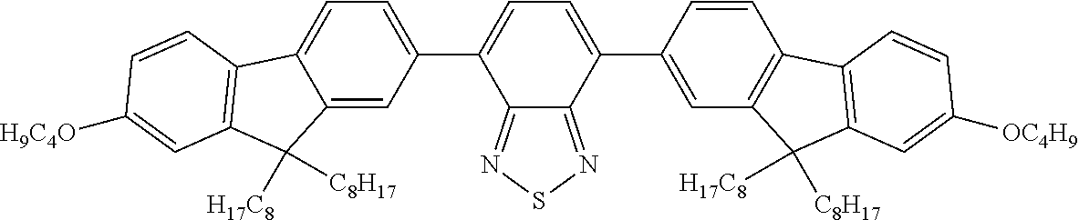 |
 |
 |
 |
 |
 |
 |
 |
 |
 |
 |
 |
 |
 |
 |
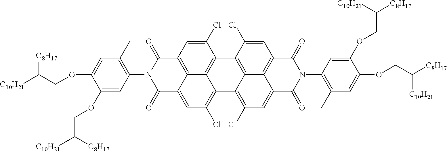 |
 |
 |
 |
 |
 |
 |
 |
 |
 |
 |
 |
 |
 |
 |
 |
 |
d<1 μm/Δn,
0.1<d/p<0.8, preferably
0.3<d/p<0.75, particularly preferably
0.4<d/p<0.7.
|
|
|
|
 |
 |
|
|
 |
 |
 |
 |
 |
 |
 |
 |
-
- 1 Substrate layer, preferably comprising glass or polymer
- 2 Electrically conductive layer
- 3 a Orientation layer O1
- 4 Switchable layer S
- 3 b Orientation layer O2
- 5 Rubbing direction in orientation layer O1
- 6 Rubbing direction in orientation layer O2
- 7 Twist angle of the liquid-crystalline compounds of the switchable layer (left-handed helix if O2 is behind O1)

| Mixture | M-1 | ||
| ne (20° C., 589.3 nm) | 1.5514 | ||
| no (20° C., 589.3 nm) | 1.4737 | ||
| Δ n (20° C., 589.3 nm) | 0.0777 | ||
| ε_parallel (20° C., 1 kHz) | 3.40 | ||
| ε_perpendicular (20° C., 1 kHz) | 7.1 | ||
| Δε (20° C., 1 kHz) | −3.7 | ||
| HTP (S-811, 20° C.) | 10.06 μm−1 | ||
| Composition | Compound | % | ||
| CY-3-O2 | 12 | |||
| CY-5-O2 | 12 | |||
| CCY-3-O2 | 13 | |||
| CCY-5-O2 | 13 | |||
| CCY-3-1 | 8 | |||
| CCZC-3-3 | 4 | |||
| CCZC-3-5 | 3 | |||
| CCZC-4-3 | 3 | |||
| CC-3-4 | 6 | |||
| CC-3-5 | 6 | |||
| CC-3-O3 | 8 | |||
| CC-5- |
4 | |||
| CC-5- |
4 | |||
| CP-3- |
4 | |||
| Mixture | M-2 | ||
| ne (20° C., 589.3 nm) | 1.5186 | ||
| no (20° C., 589.3 nm) | 1.4750 | ||
| Δ n (20° C., 589.3 nm) | 0.0436 | ||
| ε_parallel (20° C., 1 kHz) | 3.32 | ||
| ε_perpendicular (20° C., 1 kHz) | 8.11 | ||
| Δε (20° C., 1 kHz) | −4.8 | ||
| HTP (S-811, 20° C.) | 8.22 μm−1 | ||
| Composition | Compound | % | ||
| CCN-47 | 20 | |||
| CCN-55 | 21 | |||
| CC-3-O1 | 11 | |||
| CC-5- |
5 | |||
| CC-5- |
5 | |||
| CCZC-3-3 | 4 | |||
| CCZC-3-5 | 4 | |||
| CCZC-4-3 | 4 | |||
| CCZC-4-5 | 4 | |||
| BCN-55 | 22 | |||
| Mixture | M-3 | ||
| ne (20° C., 589.3 nm) | 1.5222 | ||
| no (20° C., 589.3 nm) | 1.4779 | ||
| Δ n (20° C., 589.3 nm) | 0.0443 | ||
| ε_parallel (20° C., 1 kHz) | 3.39 | ||
| ε_perpendicular (20° C., 1 kHz) | 8.94 | ||
| Δε (20° C., 1 kHz) | −5.5 | ||
| HTP (S-811, 20° C.) | |||
| Composition | Compound | % | ||
| CCN-47 | 15 | |||
| CCN-55 | 15 | |||
| CCN-33 | 8 | |||
| CCZC-3-3 | 3 | |||
| CCZC-3-5 | 3 | |||
| CC-3-O1 | 11 | |||
| CC-5- |
5 | |||
| CCZCC-2-3 | 2 | |||
| CCZCC-3-2 | 2 | |||
| CCZCC-4-2 | 2 | |||
| CCZCC-4-3 | 2 | |||
| BCN-35 | 16 | |||
| BCN-55 | 16 | |||


| Temperature | τV bright state | ΔτV | |||
| [° C.] | τV dark state [%] | [%] | [%] | ||
| 20 | 24.0 | 74.5 | 50.5 | ||
| Temperature | τV dark state | τV bright state | ΔτV | ||
| [° C.] | [%] | [%] | [%] | ||
| 20 | 29.4 | 74.4 | 45.0 | ||
| Temperature | τV dark state | τV bright state | ΔτV | ||
| [° C.] | [%] | [%] | [%] | ||
| 20 | 24.4 | 71.8 | 47.4 | ||
| Temperature | τV dark state | τV bright state | ΔτV | ||
| [° C.] | [%] | [%] | [%] | ||
| 20 | 26.1 | 72.9 | 47.4 | ||
| Temperature | τV dark state | τV bright state | ΔτV | ||
| [° C.] | [%] | [%] | [%] | ||
| 20° C. | 22.9 | 72.7 | 49.8 | ||
Claims (27)
d<1 μm/Δn
d<0.9 μm/Δn
and
d>0.2 μm/Δn.
d<1 μm/Δn
d<0.75 μm/Δn and d>0.5 μm/Δn.
Applications Claiming Priority (4)
| Application Number | Priority Date | Filing Date | Title |
|---|---|---|---|
| EP16150279 | 2016-01-06 | ||
| EP16150279.4 | 2016-01-06 | ||
| EP16150279 | 2016-01-06 | ||
| PCT/EP2016/002108 WO2017118465A1 (en) | 2016-01-06 | 2016-12-14 | Device for regulating entry of light |
Publications (2)
| Publication Number | Publication Date |
|---|---|
| US20190031959A1 US20190031959A1 (en) | 2019-01-31 |
| US10655067B2 true US10655067B2 (en) | 2020-05-19 |
Family
ID=55070865
Family Applications (1)
| Application Number | Title | Priority Date | Filing Date |
|---|---|---|---|
| US16/068,207 Active US10655067B2 (en) | 2016-01-06 | 2016-12-14 | Device for regulating the entry of light |
Country Status (7)
| Country | Link |
|---|---|
| US (1) | US10655067B2 (en) |
| EP (1) | EP3400270B1 (en) |
| JP (1) | JP7239323B2 (en) |
| KR (1) | KR20180100196A (en) |
| CN (1) | CN108603116B (en) |
| TW (1) | TWI712675B (en) |
| WO (1) | WO2017118465A1 (en) |
Cited By (1)
| Publication number | Priority date | Publication date | Assignee | Title |
|---|---|---|---|---|
| US20230053362A1 (en) * | 2018-11-23 | 2023-02-23 | Merck Patent Gmbh | Dichroic dye composition |
Families Citing this family (5)
| Publication number | Priority date | Publication date | Assignee | Title |
|---|---|---|---|---|
| EP3839620A1 (en) * | 2019-12-16 | 2021-06-23 | Merck Patent GmbH | Device for the regulation of light transmission |
| EP3940040A1 (en) | 2020-07-16 | 2022-01-19 | Merck Patent GmbH | Liquid-crystalline medium |
| KR20230150949A (en) * | 2021-03-01 | 2023-10-31 | 미쯔비시 케미컬 주식회사 | Liquid crystal devices and emulsion compositions |
| TW202317855A (en) | 2021-08-06 | 2023-05-01 | 德商馬克專利公司 | Switching layers for use in a window element |
| CN115793316A (en) * | 2022-11-30 | 2023-03-14 | 京东方科技集团股份有限公司 | Heat radiation regulation and control module, heat radiation regulation and control device and vehicle |
Citations (11)
| Publication number | Priority date | Publication date | Assignee | Title |
|---|---|---|---|---|
| US20060274218A1 (en) * | 2005-03-15 | 2006-12-07 | Jiuzhi Xue | Windows with electrically controllable transmission and reflection |
| WO2012052100A1 (en) | 2010-10-20 | 2012-04-26 | Merck Patent Gmbh | Switch element comprising a liquid-crystalline medium |
| US20130258266A1 (en) * | 2010-10-04 | 2013-10-03 | Alphamicron Incorporated | Wide band variable transmittance optical device and mixture |
| WO2014090373A1 (en) | 2012-12-13 | 2014-06-19 | Merck Patent Gmbh | Liquid-crystalline medium |
| US20140226096A1 (en) * | 2013-02-12 | 2014-08-14 | Alphamicron Inc. | Liquid crystal light variable device |
| WO2014135240A2 (en) | 2013-03-05 | 2014-09-12 | Merck Patent Gmbh | Device for regulating the passage of energy |
| WO2014180525A1 (en) | 2013-05-08 | 2014-11-13 | Merck Patent Gmbh | Device comprising two liquid crystal switching layers for regulating the passage of optical energy |
| US20140375914A1 (en) * | 2011-12-28 | 2014-12-25 | Sharp Kabushiki Kaisha | Stereoscopic display device |
| WO2015055274A1 (en) | 2013-10-17 | 2015-04-23 | Merck Patent Gmbh | Device for regulating entry of light |
| WO2015090506A1 (en) | 2013-12-19 | 2015-06-25 | Merck Patent Gmbh | Device for regulating the passage of light |
| US20150378205A1 (en) * | 2014-06-30 | 2015-12-31 | Lg Display Co., Ltd. | Light controlling apparatus and transparent display including the same |
Family Cites Families (13)
| Publication number | Priority date | Publication date | Assignee | Title |
|---|---|---|---|---|
| IT1190508B (en) * | 1986-03-24 | 1988-02-16 | Daniele Senatore | ADJUSTABLE TRANSPARENCY GLASSES |
| JPH09133930A (en) * | 1995-09-05 | 1997-05-20 | Sharp Corp | Liquid crystal display element |
| EP1083457A1 (en) * | 1999-09-07 | 2001-03-14 | Corning Incorporated | Liquid crystal matrix add/drop system |
| JP2001228482A (en) * | 1999-12-08 | 2001-08-24 | Sharp Corp | Liquid crystal display device and method of manufacturing the same |
| DE10253606A1 (en) * | 2002-11-15 | 2004-05-27 | Merck Patent Gmbh | Electro-optical light control element used in an electro-optical display system comprises one or more substrate, an electrode arrangement, one or more elements for polarizing light, and a control medium |
| JP4233443B2 (en) * | 2003-12-15 | 2009-03-04 | 日東電工株式会社 | Optical film and image display device |
| CN101059607A (en) * | 2006-04-17 | 2007-10-24 | 孙刚 | Electrically-controlled liquid crystal light modulation glass and film |
| JP5036414B2 (en) * | 2007-06-07 | 2012-09-26 | 富士フイルム株式会社 | Display materials and automotive parts |
| JP2009046525A (en) * | 2007-08-13 | 2009-03-05 | Fujifilm Corp | Liquid crystal composition and dimming material |
| GB0816557D0 (en) * | 2008-09-10 | 2008-10-15 | Merck Patent Gmbh | Electro-optical switching element and electro-optical display |
| CN103299018B (en) * | 2011-01-28 | 2015-11-25 | 默克专利股份有限公司 | Layer for light transmissive adjustment is arranged |
| US10465114B2 (en) * | 2012-12-13 | 2019-11-05 | Merck Patent Gmbh | Liquid-crystalline medium |
| KR20150140000A (en) * | 2014-06-05 | 2015-12-15 | 주식회사 소디 | The LCD Light Modulation Apparatus |
-
2016
- 2016-12-14 JP JP2018535119A patent/JP7239323B2/en active Active
- 2016-12-14 EP EP16809642.8A patent/EP3400270B1/en active Active
- 2016-12-14 KR KR1020187022473A patent/KR20180100196A/en not_active Application Discontinuation
- 2016-12-14 WO PCT/EP2016/002108 patent/WO2017118465A1/en active Application Filing
- 2016-12-14 US US16/068,207 patent/US10655067B2/en active Active
- 2016-12-14 CN CN201680078121.5A patent/CN108603116B/en active Active
-
2017
- 2017-01-05 TW TW106100237A patent/TWI712675B/en active
Patent Citations (18)
| Publication number | Priority date | Publication date | Assignee | Title |
|---|---|---|---|---|
| US20060274218A1 (en) * | 2005-03-15 | 2006-12-07 | Jiuzhi Xue | Windows with electrically controllable transmission and reflection |
| US20130258266A1 (en) * | 2010-10-04 | 2013-10-03 | Alphamicron Incorporated | Wide band variable transmittance optical device and mixture |
| WO2012052100A1 (en) | 2010-10-20 | 2012-04-26 | Merck Patent Gmbh | Switch element comprising a liquid-crystalline medium |
| US20130208227A1 (en) | 2010-10-20 | 2013-08-15 | Merck Patent Gmbh | Switch element comprising a liquid-crystalline medium |
| US20140375914A1 (en) * | 2011-12-28 | 2014-12-25 | Sharp Kabushiki Kaisha | Stereoscopic display device |
| WO2014090373A1 (en) | 2012-12-13 | 2014-06-19 | Merck Patent Gmbh | Liquid-crystalline medium |
| US20150299577A1 (en) | 2012-12-13 | 2015-10-22 | Merck Patent Gmbh | Liquid-crystalline medium |
| US20140226096A1 (en) * | 2013-02-12 | 2014-08-14 | Alphamicron Inc. | Liquid crystal light variable device |
| WO2014135240A2 (en) | 2013-03-05 | 2014-09-12 | Merck Patent Gmbh | Device for regulating the passage of energy |
| US20160033807A1 (en) | 2013-03-05 | 2016-02-04 | Merck Patent Gmbh | Device for regulating the passage of energy |
| WO2014180525A1 (en) | 2013-05-08 | 2014-11-13 | Merck Patent Gmbh | Device comprising two liquid crystal switching layers for regulating the passage of optical energy |
| US20160085108A1 (en) | 2013-05-08 | 2016-03-24 | Merck Patent Gmbh | Device for regulating the passage of energy |
| US10108058B2 (en) * | 2013-05-08 | 2018-10-23 | Merck Patent Gmbh | Device for regulating the passage of energy |
| WO2015055274A1 (en) | 2013-10-17 | 2015-04-23 | Merck Patent Gmbh | Device for regulating entry of light |
| US20160257885A1 (en) | 2013-10-17 | 2016-09-08 | Merck Patent Gmbh | Device for regulating the entry of light |
| WO2015090506A1 (en) | 2013-12-19 | 2015-06-25 | Merck Patent Gmbh | Device for regulating the passage of light |
| US20160319592A1 (en) | 2013-12-19 | 2016-11-03 | Merck Patent Gmbh | Device for regulating the passage of light |
| US20150378205A1 (en) * | 2014-06-30 | 2015-12-31 | Lg Display Co., Ltd. | Light controlling apparatus and transparent display including the same |
Non-Patent Citations (1)
| Title |
|---|
| International Search Report PCT/EP2016/002108 dated Mar. 9, 2017. |
Cited By (2)
| Publication number | Priority date | Publication date | Assignee | Title |
|---|---|---|---|---|
| US20230053362A1 (en) * | 2018-11-23 | 2023-02-23 | Merck Patent Gmbh | Dichroic dye composition |
| US11939512B2 (en) * | 2018-11-23 | 2024-03-26 | Merck Patent Gmbh | Dichroic dye composition |
Also Published As
| Publication number | Publication date |
|---|---|
| JP7239323B2 (en) | 2023-03-14 |
| KR20180100196A (en) | 2018-09-07 |
| US20190031959A1 (en) | 2019-01-31 |
| TWI712675B (en) | 2020-12-11 |
| TW201736579A (en) | 2017-10-16 |
| WO2017118465A1 (en) | 2017-07-13 |
| EP3400270B1 (en) | 2020-04-29 |
| CN108603116A (en) | 2018-09-28 |
| JP2019502958A (en) | 2019-01-31 |
| EP3400270A1 (en) | 2018-11-14 |
| CN108603116B (en) | 2022-04-29 |
Similar Documents
| Publication | Publication Date | Title |
|---|---|---|
| US10336940B2 (en) | Device for regulating the entry of light | |
| US10655067B2 (en) | Device for regulating the entry of light | |
| US10108058B2 (en) | Device for regulating the passage of energy | |
| US10626666B2 (en) | Device for regulating the passage of light | |
| US10114264B2 (en) | Device for regulating the passage of energy | |
| US20110102730A1 (en) | Liquid crystal device | |
| US10598998B2 (en) | Optical switching device |
Legal Events
| Date | Code | Title | Description |
|---|---|---|---|
| AS | Assignment |
Owner name: MERCK PATENT GMBH, GERMANY Free format text: ASSIGNMENT OF ASSIGNORS INTEREST;ASSIGNORS:JUNGE, MICHAEL;BEYER, ANDREAS;FISCHER, MILA;SIGNING DATES FROM 20180516 TO 20180606;REEL/FRAME:046270/0325 |
|
| FEPP | Fee payment procedure |
Free format text: ENTITY STATUS SET TO UNDISCOUNTED (ORIGINAL EVENT CODE: BIG.); ENTITY STATUS OF PATENT OWNER: LARGE ENTITY |
|
| STPP | Information on status: patent application and granting procedure in general |
Free format text: DOCKETED NEW CASE - READY FOR EXAMINATION |
|
| STPP | Information on status: patent application and granting procedure in general |
Free format text: NON FINAL ACTION MAILED |
|
| STPP | Information on status: patent application and granting procedure in general |
Free format text: RESPONSE TO NON-FINAL OFFICE ACTION ENTERED AND FORWARDED TO EXAMINER |
|
| STPP | Information on status: patent application and granting procedure in general |
Free format text: FINAL REJECTION MAILED |
|
| STPP | Information on status: patent application and granting procedure in general |
Free format text: NOTICE OF ALLOWANCE MAILED -- APPLICATION RECEIVED IN OFFICE OF PUBLICATIONS |
|
| STPP | Information on status: patent application and granting procedure in general |
Free format text: PUBLICATIONS -- ISSUE FEE PAYMENT VERIFIED |
|
| STCF | Information on status: patent grant |
Free format text: PATENTED CASE |
|
| MAFP | Maintenance fee payment |
Free format text: PAYMENT OF MAINTENANCE FEE, 4TH YEAR, LARGE ENTITY (ORIGINAL EVENT CODE: M1551); ENTITY STATUS OF PATENT OWNER: LARGE ENTITY Year of fee payment: 4 |