US1065371A - Support for electric lights. - Google Patents
Support for electric lights. Download PDFInfo
- Publication number
- US1065371A US1065371A US70818312A US1912708183A US1065371A US 1065371 A US1065371 A US 1065371A US 70818312 A US70818312 A US 70818312A US 1912708183 A US1912708183 A US 1912708183A US 1065371 A US1065371 A US 1065371A
- Authority
- US
- United States
- Prior art keywords
- arms
- cross bar
- lamps
- adjusted
- vertical
- Prior art date
- Legal status (The legal status is an assumption and is not a legal conclusion. Google has not performed a legal analysis and makes no representation as to the accuracy of the status listed.)
- Expired - Lifetime
Links
- 238000011282 treatment Methods 0.000 description 7
- 238000010168 coupling process Methods 0.000 description 4
- 238000005859 coupling reaction Methods 0.000 description 4
- 230000001225 therapeutic effect Effects 0.000 description 4
- 230000008878 coupling Effects 0.000 description 3
- 230000004048 modification Effects 0.000 description 2
- 238000012986 modification Methods 0.000 description 2
- 238000010276 construction Methods 0.000 description 1
- 210000003811 finger Anatomy 0.000 description 1
- 210000003813 thumb Anatomy 0.000 description 1
Images
Classifications
-
- F—MECHANICAL ENGINEERING; LIGHTING; HEATING; WEAPONS; BLASTING
- F21—LIGHTING
- F21V—FUNCTIONAL FEATURES OR DETAILS OF LIGHTING DEVICES OR SYSTEMS THEREOF; STRUCTURAL COMBINATIONS OF LIGHTING DEVICES WITH OTHER ARTICLES, NOT OTHERWISE PROVIDED FOR
- F21V19/00—Fastening of light sources or lamp holders
- F21V19/02—Fastening of light sources or lamp holders with provision for adjustment, e.g. for focusing
Definitions
- This invention relates to improvements in supports for electric lights for therapeutic purposes.
- the main objects of this invention are, I first, to provide improved supports for electrio lights for therapeutic purposes which E may be easily adjusted for the treatment of patient in a sittin tion, or to treat ilferent portions of the body. Second, to provide improved supports for electric lights for therapeutic purposes having these advantages, which is portable. Third, to provide a structure having these advantages which may be easily and quickly adjusted and is simple and eco nomical in structure. Fourth, to provide improved supports for electric lights for therapeutic purposes which is adapted for use as an electric heater.
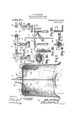
- FIG. I is a perspective view of a structure embodying the features of my invention, the covering 18 being shown in section, the electrical connections 16 being illustrated for only two of the lamps, a person being shown by dotted lines in sitting position.
- Fig. II is a detail view partially in section on a line co-rrespondng to line 22 of Fig. I, showing details of the frame and of the lamp brackets and their arrangement on the frame.
- Fig. III is a detail side elevation of one of the lamp brackets, its supporting arm 6 being shown in section.
- Fig. IV is a detail vertical section, on a line corresponding to line 4-4 of Fig. I, showing the connection Specification of Letters Patent.
- Fig. I is a section through one of thelamp sockets taken on a line corresponding to line 55 of Fig. I, showing the mounting of the lamp reflectors 20.
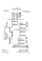
- Fig. VI is a detail elevation showing one adjustment of the lamps.
- Fig. VII is a detail plan showing another adjustment of the lamps, the lamps being adjusted for the treatment of-the patient in the reclining position. elevation showing the another position. tion showing the lamps adjusted 'to still another position.
- Fig. X is a detail view showing the wiring of the lamps.
- Fig. XI is a detail view showin the arrangement of the end bracket 19. 1g. XII is a vertical lamps adjusted to standard or upright is mounted upon a Wall
- similar reference characters refer to similar parts throughout the several views. and the sectional views are taken looking in the direction of the little arrows at the ends of the section lines.
- I provide an upright or standard I mounted on a base 2.
- a cross bar 3 is mounted on the upright or standard 1 for vertical adjustment thereon, the T-coupling 4 being in sliding engagement with the upright and being secured in its adjusted positions thereon by means of the thumb screw 5.
- the cross bar 3 and arms 6 are preferably square in cross section and the couplings made to correspond so that the arms are supported either in their vertical or horizontal positions according to the manner of engagement of the coupling therewith.
- Set screws 8 retain the arms in their adjusted positions on the cross pieces. The arms can be readily removed from the cross bar.
- the lamps 9 are carried by brackets 10 which are a'djustably mounted on the arms 6 or on the cross bar to meet the requirements of the case to be treated.
- the brackets 10 areprovided with set screws 11 for securing them in their adjusted position.
- the brackets 10 are angled and forked at their lower ends and provided for the cross bar, 3 to the upright 1. Fig. V
- Fig. IX is a detail elevaend of a modified construction in which the- 3 as may be desired to adjust the apparatus Fig. VIII is a detail instead of upon a base, as is shown in Fig. I.
- slots 13 are augular,l1aving vertical portions and horizontal portions connected by curves.
- the curved port-ions of the blocks are notched at 16 to provide supports for the lamps, the notches being engaged by the T arms 14 on the sockets.
- the lamps are thus supported in their adjusted positions, either vertically or horizontally or in any intermediate position. This provides a simple and e .ective adjustment for the lamps on their supporting bracket.
- the wires 22 are connected to the lamp sockets through the tubular T-arms 14.
- the lamp sockets 15 are provided with switches 17 so that the lamps areindividually controlled.
- the outer covering 18 is of flexible material and is adapted to be thrown over the standard and supported by the cross bar 3 and the arms (5.
- L-shaped extensions 19 are preferably provided for the ends of the arms to hold the covering away from the lamps, the extension being telescoped into the arms,-see Fig. XI.
- the lamps are preferably provided with reflectors 20 having spring champing fingers 21 and adapted to embrace the socket. See Figs. 1 and V.
- the reflectors can be readily removed or adjusted according to the adjustment of the lamps. For instance, if the lamps are adjusted in their brackets from a vertical to a horizontal position, the reflectors would be on the under side of the lamps unless they were reversed. This mounting permits their being quickly reversed or ad usted.
- the frame structure and the lamps upon the frame as I have illustrated, it is readily adjusted to any desired position for the treatment of a person in a sitting or in a reclining position, or for the treatment of different portions of the body.
- Figs. VI and IX I show the lamps adjusted in different positions.
- the standard or upright 23 is mounted by means of wall brackets 24:.
- the portable form is, however, preferred, as it may be taken from room to room or adjusted for-the treatment of a patient in bed, or on a couch, or in connection with a bath tub, or various other relations, as will be suggested to those using the apparatus. Or the apparatus may be taken from house to house by a physician or person giving the treatments as it can be quickly knocked down or disassembled and as readily reassembled.
Landscapes
- Engineering & Computer Science (AREA)
- General Engineering & Computer Science (AREA)
- Accommodation For Nursing Or Treatment Tables (AREA)
Description
J. H. KELLOGG.
SUPPORT FOR ELECTRIC LIGHTS.
APPLICATION IILED JULY 8; 1912.
Patented June 24,1913.
2 SHEETS-SHEET 1 J. HLKELLOGG.
SUPPORT FOR ELECTRIC LIGHTS.
APPLICATION FILED JULY 8, 1912.
Patented June 24,1913.
2 SHEETS-SHEET 2.
gif it? UNITED STATES PA ENT orr on.
JOHN H. KELLOGG, OF BATTLE GREEK, MICHIGAN, ASSIGNOR TO SA NITARIUM EQUIP- MEN'T COMPANY, or BATTLE CREEK,
MICHIGAN.
SUPPORT FOR ELECTRIC LIGHTS.
To all whom it may concern:
Be it known that I, JOHN H. KnLLoec, a citizen of the United States, residing at the city of Battle Creek, county of Calhoun, and State of Michigan, have invented certain new and useful Improvements in Supports for Electric Lights, of which the following is a specification.
This invention relates to improvements in supports for electric lights for therapeutic purposes.
The main objects of this invention are, I first, to provide improved supports for electrio lights for therapeutic purposes which E may be easily adjusted for the treatment of patient in a sittin tion, or to treat ilferent portions of the body. Second, to provide improved supports for electric lights for therapeutic purposes having these advantages, which is portable. Third, to provide a structure having these advantages which may be easily and quickly adjusted and is simple and eco nomical in structure. Fourth, to provide improved supports for electric lights for therapeutic purposes which is adapted for use as an electric heater.
Further objects, and objects relating to structural details, will definitely appear from the detailed description to follow.
I accomplish the objects of my invention by the devices and means described in the following specification.
The invention is clearly defined and pointed out in the claims.
A structure which is a preferred embodiment of my invention is clearly illustrated in the accompanying drawing, forming a part of this specification, in which Figure I is a perspective view of a structure embodying the features of my invention, the covering 18 being shown in section, the electrical connections 16 being illustrated for only two of the lamps, a person being shown by dotted lines in sitting position. Fig. II is a detail view partially in section on a line co-rrespondng to line 22 of Fig. I, showing details of the frame and of the lamp brackets and their arrangement on the frame. Fig. III is a detail side elevation of one of the lamp brackets, its supporting arm 6 being shown in section. Fig. IV is a detail vertical section, on a line corresponding to line 4-4 of Fig. I, showing the connection Specification of Letters Patent.
Application filed July 8, 1912.
or in a reclining posi- F Patented June 2 1, i913. semi No. 708,183.
I is a section through one of thelamp sockets taken on a line corresponding to line 55 of Fig. I, showing the mounting of the lamp reflectors 20. Fig. VI is a detail elevation showing one adjustment of the lamps. Fig. VII is a detail plan showing another adjustment of the lamps, the lamps being adjusted for the treatment of-the patient in the reclining position. elevation showing the another position. tion showing the lamps adjusted 'to still another position. Fig. X is a detail view showing the wiring of the lamps. Fig. XI is a detail view showin the arrangement of the end bracket 19. 1g. XII is a vertical lamps adjusted to standard or upright is mounted upon a Wall In the drawing, similar reference characters refer to similar parts throughout the several views. and the sectional views are taken looking in the direction of the little arrows at the ends of the section lines.
In the structure shown in Fig. I, which is an embodiment of my invention in portable form, I provide an upright or standard I mounted on a base 2. A cross bar 3 is mounted on the upright or standard 1 for vertical adjustment thereon, the T-coupling 4 being in sliding engagement with the upright and being secured in its adjusted positions thereon by means of the thumb screw 5. 0n the cross bar 3, I mount arms 6, the arms being adjustably secured on the cross bar by means of couplings 7. The cross bar 3 and arms 6 are preferably square in cross section and the couplings made to correspond so that the arms are supported either in their vertical or horizontal positions according to the manner of engagement of the coupling therewith. Set screws 8 retain the arms in their adjusted positions on the cross pieces. The arms can be readily removed from the cross bar. The lamps 9 are carried by brackets 10 which are a'djustably mounted on the arms 6 or on the cross bar to meet the requirements of the case to be treated. The brackets 10 areprovided with set screws 11 for securing them in their adjusted position. The brackets 10 are angled and forked at their lower ends and provided for the cross bar, 3 to the upright 1. Fig. V
Fig. IX is a detail elevaend of a modified construction in which the- 3 as may be desired to adjust the apparatus Fig. VIII is a detail instead of upon a base, as is shown in Fig. I.
with slots 13 in their arms adapted to receive the T-arms 14 on the lamp sockets 15. The
slots 13 are augular,l1aving vertical portions and horizontal portions connected by curves. The curved port-ions of the blocks are notched at 16 to provide supports for the lamps, the notches being engaged by the T arms 14 on the sockets. The lamps are thus supported in their adjusted positions, either vertically or horizontally or in any intermediate position. This provides a simple and e .ective adjustment for the lamps on their supporting bracket. The wires 22 are connected to the lamp sockets through the tubular T-arms 14. The lamp sockets 15 are provided with switches 17 so that the lamps areindividually controlled. The outer covering 18 is of flexible material and is adapted to be thrown over the standard and supported by the cross bar 3 and the arms (5. L-shaped extensions 19 are preferably provided for the ends of the arms to hold the covering away from the lamps, the extension being telescoped into the arms,-see Fig. XI. The lamps are preferably provided with reflectors 20 having spring champing fingers 21 and adapted to embrace the socket. See Figs. 1 and V. By this arrangement, the reflectors can be readily removed or adjusted according to the adjustment of the lamps. For instance, if the lamps are adjusted in their brackets from a vertical to a horizontal position, the reflectors would be on the under side of the lamps unless they were reversed. This mounting permits their being quickly reversed or ad usted.
By arranging the frame structure and the lamps upon the frame as I have illustrated, it is readily adjusted to any desired position for the treatment of a person in a sitting or in a reclining position, or for the treatment of different portions of the body. In Figs. VI and IX, I show the lamps adjusted in different positions. In the modification shovvnin Fig. XII, the standard or upright 23 is mounted by means of wall brackets 24:. The portable form is, however, preferred, as it may be taken from room to room or adjusted for-the treatment of a patient in bed, or on a couch, or in connection with a bath tub, or various other relations, as will be suggested to those using the apparatus. Or the apparatus may be taken from house to house by a physician or person giving the treatments as it can be quickly knocked down or disassembled and as readily reassembled.
I have illustrated and described my improved electric light bath and treatment apparatus in a simple and eifective embodiment thereof. I have not attempted to show various modifications which are ossible and which I contemplate as the disc osure made will enable those skilled in the art to embody ineaavi my invention as conditions or taste may dictate. I desire, however, to be understood as claiming my improvements specifically in the form illustrated as well as broadly within the scope of the appended claims.
Having thus described my invention, what I claim as new and desire to secure by Letters Patentis:
1. In a structure of the class described, the
combination of,-an upright; a cross bar mounted on said upright for vertical adjustment thereon; arms mounted on said cross bar for adjustment longitudinally thereof, said arms being adapted to be arranged in a vertical or in a horizontal position on said cross bar;-lamp brackets mounted on said arms for adjustment longitudinally thereof, said brackets being adapted to be arranged in vertical or in horizontal positions on said arms and cross bar; lamps on said brackets; and reflectors for said lamps adjustably mounted thereon.
2. In a structure of the class described, the combination of an upright; a cross bar; arms mounted on said cross bar to be adjusted longitudinally thereon, said arms being arranged to be adjusted in a vertical or horizontal position on said cross bar; lamp brackets mounted on said arms for adjustment longitudinally thereon and adapted to be arranged in vertical or horizontal positions on said arms; and lamps adjustably mounted on said brackets.
3. In a structure of the class described, the combination of an upright; a cross bar; arms mounted on said crossbar to be adjusted longitudinally thereon, said arms being arranged to be adjusted in a vertical or horizontal position on said cross bar; lamp brackets mounted on said arms for adjustmentlongitudinally thereon and adapted to be arranged in vertical or horizontal positions on said arms; and lamps mounted on said brackets.
4. In a structure of the class described, the combination with a supporting arm, of forked lamp brackets adjustably mounted on said arm, the bracket forks being angularly slotted, andilamp sockets having T-arms engaging said bracket slot-s, the slots being notched to engage said socket arms toadjustably support the same.
In a structure of the class described, the combination of an upright, a horizontal cross bar mounted on said upright for vertical adjustment thereon, arms mounted on said cross bar to be adjusted longitudinally thereon and adapted to be independently adjusted to vertical or horizontal positions on said cross bar, and a plurality of lamps mounted on each of said arms to be independently adjusted longitudinally thereon and adapted to be arranged thereon in vertical or horizontal positions when said arms are in horizontal positions or in horizontal positions in the plane of said cross bar When said arms are in a vertical or in horizontal positions at right angles to the plane of said cross bar.
6. In a structure of the class described, the combination of an upright, a horizontal cross bar on said upright, a plurality of arms removably mounted on said cross bar and adapted to be adjusted to a vertical or a horizontal position thereon, and lamps removably mounted on said arms and adapted to be adjusted to vertical or horizontal positions on said arms and cross bar.
7. In a structure of the class described, the combination of an upright, a horizontal cross bar, a plurality of arms mounted v,on said cross bar and adapted to be adjusted thereon to and from each other and a plurality of lamps mounted on said arms to be independently adjusted longitudinally thereof and adapted to be arranged in horizontal or vertical positions thereon.
8. In a structure of the class described, the combination of an upright, a horizontal cross bar on said upright, a plurality of arms mounted on said cross bar for independent adjustment longitudinally thereon, and a plurality of lamps -mounted on said arms for independent adjustment longitudinally thereon andadapted to be arranged in vertical or horizontal positions on said arms.
9. In a structure of the class described,the
combination of an upright, a horizontal cross bar on said upright, a plurality of arms mounted on said cross bar for independent nesses.
JOHN H. KELLOGG. [1,. s.] Witnesses:
R. V. Asmara: 'S. B. TENNEY.
Priority Applications (1)
| Application Number | Priority Date | Filing Date | Title |
|---|---|---|---|
| US70818312A US1065371A (en) | 1912-07-08 | 1912-07-08 | Support for electric lights. |
Applications Claiming Priority (1)
| Application Number | Priority Date | Filing Date | Title |
|---|---|---|---|
| US70818312A US1065371A (en) | 1912-07-08 | 1912-07-08 | Support for electric lights. |
Publications (1)
| Publication Number | Publication Date |
|---|---|
| US1065371A true US1065371A (en) | 1913-06-24 |
Family
ID=3133614
Family Applications (1)
| Application Number | Title | Priority Date | Filing Date |
|---|---|---|---|
| US70818312A Expired - Lifetime US1065371A (en) | 1912-07-08 | 1912-07-08 | Support for electric lights. |
Country Status (1)
| Country | Link |
|---|---|
| US (1) | US1065371A (en) |
-
1912
- 1912-07-08 US US70818312A patent/US1065371A/en not_active Expired - Lifetime
Similar Documents
| Publication | Publication Date | Title |
|---|---|---|
| US1639753A (en) | Hair drier and therapeutic lamp | |
| US5086769A (en) | Tanning chair | |
| US4232901A (en) | Adjustable ottoman | |
| US1279120A (en) | Electrotherapeutical chair. | |
| US2695413A (en) | Ventilating device for beds | |
| US20190125604A1 (en) | Dental treatment machine with a retractable backrest for children | |
| US1376593A (en) | Therapeutic apparatus | |
| US1656777A (en) | Combination heat and light therapy lamp | |
| US1938237A (en) | Arc lamp cabinet | |
| US2666213A (en) | Bed construction | |
| US3196468A (en) | Therapeutic accessory for beds | |
| US2745949A (en) | Hospital floor lamp | |
| US3592146A (en) | Suspended table | |
| US1521610A (en) | Lighting outfit for photographic work | |
| US1440906A (en) | Bed attachment | |
| US3116088A (en) | Polygonal electric lighting dining table | |
| US2138563A (en) | Dental operating unit | |
| US2031643A (en) | Combination chair and lamp | |
| US1743963A (en) | Hair-drying machine | |
| US624869A (en) | And james h | |
| US1711839A (en) | Therapeutic light apparatus | |
| US20210093477A1 (en) | Leg Joint Therapy Apparatus | |
| US2590673A (en) | Vacuum cleaner for barber chairs | |
| RU2067409C1 (en) | Convertible sleeping and playing complex for children | |
| US1137753A (en) | Table attachment for beds. |