US10653329B2 - Planar neural probe structure and its assembly structure for chronic implantation - Google Patents
Planar neural probe structure and its assembly structure for chronic implantation Download PDFInfo
- Publication number
- US10653329B2 US10653329B2 US15/721,217 US201715721217A US10653329B2 US 10653329 B2 US10653329 B2 US 10653329B2 US 201715721217 A US201715721217 A US 201715721217A US 10653329 B2 US10653329 B2 US 10653329B2
- Authority
- US
- United States
- Prior art keywords
- neural probe
- nerve
- neural
- probe structure
- cover
- Prior art date
- Legal status (The legal status is an assumption and is not a legal conclusion. Google has not performed a legal analysis and makes no representation as to the accuracy of the status listed.)
- Active, expires
Links
Images


Classifications
-
- A—HUMAN NECESSITIES
- A61—MEDICAL OR VETERINARY SCIENCE; HYGIENE
- A61N—ELECTROTHERAPY; MAGNETOTHERAPY; RADIATION THERAPY; ULTRASOUND THERAPY
- A61N1/00—Electrotherapy; Circuits therefor
- A61N1/02—Details
- A61N1/04—Electrodes
-
- A61B5/04001—
-
- A—HUMAN NECESSITIES
- A61—MEDICAL OR VETERINARY SCIENCE; HYGIENE
- A61B—DIAGNOSIS; SURGERY; IDENTIFICATION
- A61B5/00—Measuring for diagnostic purposes; Identification of persons
- A61B5/24—Detecting, measuring or recording bioelectric or biomagnetic signals of the body or parts thereof
-
- A—HUMAN NECESSITIES
- A61—MEDICAL OR VETERINARY SCIENCE; HYGIENE
- A61B—DIAGNOSIS; SURGERY; IDENTIFICATION
- A61B5/00—Measuring for diagnostic purposes; Identification of persons
- A61B5/40—Detecting, measuring or recording for evaluating the nervous system
-
- A—HUMAN NECESSITIES
- A61—MEDICAL OR VETERINARY SCIENCE; HYGIENE
- A61B—DIAGNOSIS; SURGERY; IDENTIFICATION
- A61B5/00—Measuring for diagnostic purposes; Identification of persons
- A61B5/68—Arrangements of detecting, measuring or recording means, e.g. sensors, in relation to patient
- A61B5/6846—Arrangements of detecting, measuring or recording means, e.g. sensors, in relation to patient specially adapted to be brought in contact with an internal body part, i.e. invasive
- A61B5/6867—Arrangements of detecting, measuring or recording means, e.g. sensors, in relation to patient specially adapted to be brought in contact with an internal body part, i.e. invasive specially adapted to be attached or implanted in a specific body part
- A61B5/6877—Nerve
-
- A—HUMAN NECESSITIES
- A61—MEDICAL OR VETERINARY SCIENCE; HYGIENE
- A61N—ELECTROTHERAPY; MAGNETOTHERAPY; RADIATION THERAPY; ULTRASOUND THERAPY
- A61N1/00—Electrotherapy; Circuits therefor
- A61N1/02—Details
- A61N1/04—Electrodes
- A61N1/0404—Electrodes for external use
- A61N1/0408—Use-related aspects
- A61N1/0456—Specially adapted for transcutaneous electrical nerve stimulation [TENS]
-
- A—HUMAN NECESSITIES
- A61—MEDICAL OR VETERINARY SCIENCE; HYGIENE
- A61N—ELECTROTHERAPY; MAGNETOTHERAPY; RADIATION THERAPY; ULTRASOUND THERAPY
- A61N1/00—Electrotherapy; Circuits therefor
- A61N1/02—Details
- A61N1/04—Electrodes
- A61N1/05—Electrodes for implantation or insertion into the body, e.g. heart electrode
- A61N1/0551—Spinal or peripheral nerve electrodes
- A61N1/0556—Cuff electrodes
-
- A—HUMAN NECESSITIES
- A61—MEDICAL OR VETERINARY SCIENCE; HYGIENE
- A61N—ELECTROTHERAPY; MAGNETOTHERAPY; RADIATION THERAPY; ULTRASOUND THERAPY
- A61N1/00—Electrotherapy; Circuits therefor
- A61N1/02—Details
- A61N1/04—Electrodes
- A61N1/05—Electrodes for implantation or insertion into the body, e.g. heart electrode
- A61N1/0551—Spinal or peripheral nerve electrodes
- A61N1/0558—Anchoring or fixation means therefor
-
- A—HUMAN NECESSITIES
- A61—MEDICAL OR VETERINARY SCIENCE; HYGIENE
- A61N—ELECTROTHERAPY; MAGNETOTHERAPY; RADIATION THERAPY; ULTRASOUND THERAPY
- A61N1/00—Electrotherapy; Circuits therefor
- A61N1/18—Applying electric currents by contact electrodes
- A61N1/32—Applying electric currents by contact electrodes alternating or intermittent currents
- A61N1/36—Applying electric currents by contact electrodes alternating or intermittent currents for stimulation
- A61N1/3605—Implantable neurostimulators for stimulating central or peripheral nerve system
-
- A—HUMAN NECESSITIES
- A61—MEDICAL OR VETERINARY SCIENCE; HYGIENE
- A61B—DIAGNOSIS; SURGERY; IDENTIFICATION
- A61B2562/00—Details of sensors; Constructional details of sensor housings or probes; Accessories for sensors
- A61B2562/02—Details of sensors specially adapted for in-vivo measurements
- A61B2562/0209—Special features of electrodes classified in A61B5/24, A61B5/25, A61B5/283, A61B5/291, A61B5/296, A61B5/053
Definitions
- Patent Literature 1 Korean Patent No. 10-1159252
- the present disclosure is designed to solve the problem of the related art, and therefore, the present disclosure is directed to providing a neural probe structure that can be fixed very firmly and stably to a nerve, and a neural probe assembly having the same.
- the neural probe structure includes a plurality of probes, and the probes are each arranged in rows side by side in a widthwise direction of the body.
- the body has a shape of a thin flat plate, and the neural probe structure is fixed to the nerve such that one side surface defining a thickness of the body stands facing a circumferential surface of the nerve.
- the body of the neural probe structure has a polygonal shape with one open side, and the polygon has rounded corners.
- the body is formed in a square shape with one open side, including a fixing part to which the probe is fixed, and supporting parts extending from two ends of the fixing part in an extension direction of the probe.
- a neural probe assembly including the neural probe structure, wherein the neural probe structure is fixed to the nerve such that the probe passes through the nerve, and the body encloses at least a part of circumference of the nerve.
- the neural probe assembly includes a plurality of neural probe structures, the plurality of neural probe structures is fixed to the nerve such that the neural probe structures are arranged side by side along a lengthwise direction of the nerve, and the probes of each neural probe structure are inserted into the nerve such that the probes are oriented in different directions.
- the probes of adjacent neural probe structures are inserted into the nerve, forming an angle of 90° therebetween when viewed in the lengthwise direction of the nerve.
- the plurality of neural probe structures is bound together by a suture after the neural probe structures are fixed to the nerve.
- the body of the neural probe structure has a shape of a thin plate
- the neural probe assembly further includes a cover which encloses the neural probe structure fixed to the nerve in order to fix the neural probe structure while preventing the neural probe structure from being inclined in a lengthwise direction of the nerve.
- the engaging part is placed radially when viewed in the lengthwise direction of the nerve.
- FIG. 1 shows a neural probe assembly according to an embodiment of the present disclosure.
- FIG. 2 shows a neural probe structure according to an embodiment of the present disclosure.
- FIG. 3 shows fixing of the neural probe structure of FIG. 2 to a nerve using an insertion device.
- FIG. 5 is a cross-sectional view of the neural probe assembly of FIG. 1 in which a cover is shown as being cut in the lengthwise direction.
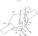
- FIG. 6 is a cross-sectional view of a neural probe assembly including a cover according to another embodiment.
- FIG. 1 shows a neural probe assembly 10 according to an embodiment of the present disclosure.
- a cover 300 is shown as being cut in the radial direction for convenience of description.
- the body 110 of the neural probe structure 100 is bent to enclose at least a part of the circumference of the nerve 20 .
- the term “enclose” as used herein should be understood as the body enclosing the nerve in contact with the circumference of the nerve as well as apart from the circumference of the nerve in whole or in part.
- the body 110 of the neural probe structure 100 has a square shape as a whole. Furthermore, the body 110 has an approximately “ ⁇ ” shape with an opening 114 on one side, including a fixing part 111 to which the probes 120 are fixed, and two supporting parts 112 extending from two ends of the fixing part 111 in the extension direction of the probes 120 .
- the body 110 has a seating groove 115 which is cut as much as a predetermined area from the opening 114 to allow the nerve 20 to be seated.
- the probes 120 extend within the seating groove 115 , and extend from one side surface 116 of the fixing part 111 toward the opening 114 .
- the body 110 of the neural probe structure 100 has an approximately “ ⁇ ” shape, but is not limited thereto. If the body has such a shape that it is bent to enclose at least a part of the circumference of the nerve 20 , the body of the neural probe structure 100 may have, for example, a different polygonal shape with one open side, and may have a curved shape like the letter “C”.
- the body 110 of the neural probe structure 100 may have slight elasticity, and may be formed such that the width of the opening 114 and the seating groove 115 is smaller than the diameter of the nerve 20 .
- the body 110 of the neural probe structure 100 has rigidity, and is formed such that the width of the opening 114 and the seating groove 115 is substantially equal to or slightly greater than the diameter of the nerve 20 .
- the corners of the square body are rounded to avoid causing the body 110 of the neural probe structure 100 to damage tissues in the body.
- Holes 113 for suture connection are formed near the corners of the square body 110 .
- the probes 120 are formed integrally with the body 110 such that they have the same thickness as the thickness of the body 110 .
- the electric wire 122 extends longitudinally over the upper surface of the fixing part 111 of the body 110 to a connector 130 connected to the rear end of the fixing part 111 .
- the connector 130 is connected to the rear end part of the body 110 , and is made of a flexible material so that it can freely bend and deform with respect to the body 110 .
- the connector 130 to which a PCB substrate (not shown) is connected enables it to collect and process signals detected from the electrodes 121 .
- the connector 130 may be omitted. In the drawings other than FIG. 2 , the illustration of the connector 130 is omitted.
- FIG. 3 shows fixing of the neural probe structure 100 to the nerve 20 using an insertion device 30 . It should be understood that the insertion device 30 is conceptually shown in FIG. 3 .
- the fixing part 111 and the supporting parts 112 of the body 110 support the circumference of the nerve 20 on three sides to provide a predetermined amount of fixing strength for stably fixing the neural probe structure 100 to the nerve 20 .
- the probes 120 can be stably fixed to the nerve 20 , and signal acquisition and/or electrical stimulation can be performed on the nerve 20 with excellent selectivity and scope.
- the other neural probe structure 100 ′ is fixed to the nerve 20 .
- the neural probe structure 100 ′ is configured identically to the neural probe structure 100 .
- the prime symbol (′) is attached to reference signs designating the neural probe structure 100 ′ and its elements, but this is for distinguishing the neural probe structure 100 ′ from the neural probe structure 100 , and it should be understood that elements indicated by the same figure are substantially the same element throughout the drawings.
- This task may be performed, for example, by fixing one neural probe structure 100 , turning the insertion device 30 by 90°, and fixing the other neural probe structure 100 ′, or otherwise, by fixing one neural probe structure 100 , turning the nerve 20 by 90°, and fixing the other neural probe structure 100 ′.
- the corresponding task may be differently selected depending on operation environment or conditions.
- the spacer 200 includes a cutout part 210 for insertion into the nerve 20 , and an installation part 211 that approximately fits the diameter of the nerve 20 at the center.
- the spacer 200 according to this embodiment is made of an elastic material (for example, biocompatible rubber), and is designed to be inserted into the nerve 20 with the cutout part 210 slightly open when installing.
- the two neural probe structures 100 , 100 ′ fixed to the nerve 20 are viewed in the lengthwise direction L of the nerve 20 , the two neural probe structures 100 , 100 ′ form a sort of a closed loop that completely encloses the circumference of the nerve 20 .
- the two neural probe structures 100 , 100 ′ are bound together, even if the neural probe structure 100 makes a movement in the opposite direction to the opening 114 , the movement is restrained by the neural probe structure 100 ′. Similarly, even if the neural probe structure 100 ′ makes a movement in the opposite direction to the opening 114 ′, the movement is restrained by the neural probe structure 100 .
- FIG. 4D shows binding of the two neural probe structures 100 , 100 ′.
- FIG. 5 is a cross-sectional view of the neural probe assembly 10 in which the cover 300 is shown as being cut in the lengthwise direction.
- Openings 340 larger than the diameter of the nerve 20 are formed at the left and right ends of the cover 300 , and the nerve 20 goes through the cover 300 and extends via the openings 340 . Accordingly, the cover 300 is not directly fixed to the nerve 20 , and is fixed in position spaced apart from the nerve 20 by the neural probe structures 100 , 100 ′.
- the connector 130 of the neural probe structure 100 may be appropriately bent and exposed to the outside through the opening 340 of the cover 300 .
- a slit that fits the width of the connector 130 may be formed through the cover 300 at an appropriate position of the cover 300 , so that the connector 130 may go outward through the slit.
- the inner space 330 is formed within the cover 300 to receive the neural probe structures 100 , 100 ′ and the spacer 200 .
- the inner space 330 includes a seating part 313 having approximately the same width T as the sum of the widths of the neural probe structures 100 , 100 ′ and the spacer 200 , and a convex part 312 formed convexly at the side of the neural probe structures 100 , 100 ′ to support the outward rotation of the neural probe structures 100 , 100 ′.
- the inclination of the neural probe structures 100 , 100 ′ in the lengthwise direction of the nerve 20 is prevented by support of the seating part 313 and the convex part 312 , thereby preventing a slip phenomenon.
- the seating part 313 has engaging parts 311 into which the round corners of the body of the neural probe structure can be inserted.
- the engaging parts 311 of the same shape are arranged radially when viewed in the lengthwise direction L of the nerve 20 to form a groove as if it has a serrated shape.
- a relative location of the cover 300 to the neural probe structures 100 , 100 ′ can be freely selected, thereby overcoming the limitation on operation space.
- the spacer 200 is placed between the neural probe structures 100 , 100 ′, but is not limited thereto.
- the spacer 200 brings the neural probe structures 100 , 100 ′ into close contact with each other through the spacer, and this function can be also achieved through the shape of the cover 300 .
- the cover 300 may include a protrusion 314 with an approximately ring shape in the inner space 330 .
- the protrusion 314 is disposed between the two neural probe structures 100 , 100 ′ to replace the function of the spacer 200 (the process of FIG. 4C can be omitted).
- the electrodes can be firmly fixed within the nerve while minimizing damage to the nerve, allowing for appropriate neural signal acquisition and/or stimulation delivery.
Landscapes
- Health & Medical Sciences (AREA)
- Life Sciences & Earth Sciences (AREA)
- Animal Behavior & Ethology (AREA)
- Engineering & Computer Science (AREA)
- Biomedical Technology (AREA)
- Veterinary Medicine (AREA)
- Public Health (AREA)
- General Health & Medical Sciences (AREA)
- Heart & Thoracic Surgery (AREA)
- Radiology & Medical Imaging (AREA)
- Nuclear Medicine, Radiotherapy & Molecular Imaging (AREA)
- Neurology (AREA)
- Surgery (AREA)
- Molecular Biology (AREA)
- Medical Informatics (AREA)
- Physics & Mathematics (AREA)
- Pathology (AREA)
- Biophysics (AREA)
- Neurosurgery (AREA)
- Orthopedic Medicine & Surgery (AREA)
- Cardiology (AREA)
- Physiology (AREA)
- Electrotherapy Devices (AREA)
Abstract
Description
Claims (15)
Applications Claiming Priority (2)
| Application Number | Priority Date | Filing Date | Title |
|---|---|---|---|
| KR1020160149218A KR101887024B1 (en) | 2016-11-10 | 2016-11-10 | Neural Probe Structure and Neural Probe Assembly having the same |
| KR10-2016-0149218 | 2016-11-10 |
Publications (2)
| Publication Number | Publication Date |
|---|---|
| US20180125427A1 US20180125427A1 (en) | 2018-05-10 |
| US10653329B2 true US10653329B2 (en) | 2020-05-19 |
Family
ID=62065840
Family Applications (1)
| Application Number | Title | Priority Date | Filing Date |
|---|---|---|---|
| US15/721,217 Active 2038-10-02 US10653329B2 (en) | 2016-11-10 | 2017-09-29 | Planar neural probe structure and its assembly structure for chronic implantation |
Country Status (2)
| Country | Link |
|---|---|
| US (1) | US10653329B2 (en) |
| KR (1) | KR101887024B1 (en) |
Families Citing this family (5)
| Publication number | Priority date | Publication date | Assignee | Title |
|---|---|---|---|---|
| KR102174093B1 (en) * | 2018-07-25 | 2020-11-05 | 한국과학기술연구원 | Apparatus for insertion of nerve electrode structure |
| KR102190211B1 (en) | 2018-08-23 | 2020-12-11 | 한국과학기술연구원 | Chronic Implantable Neural Probe Array For Neural Signal Acquisition and Stimulation |
| US11596787B2 (en) * | 2019-03-28 | 2023-03-07 | Board Of Regents, The University Of Texas System | Peripheral nerve electrode for neural recording and stimulation |
| KR102339479B1 (en) | 2019-10-21 | 2021-12-16 | 한국과학기술연구원 | Compact multi functional nerve electrode system for neural interface |
| US11617882B2 (en) | 2019-10-24 | 2023-04-04 | Korea Institute Of Science And Technology | Apparatus for insertion of nerve electrode structure |
Citations (20)
| Publication number | Priority date | Publication date | Assignee | Title |
|---|---|---|---|---|
| JP2001157669A (en) | 1999-12-03 | 2001-06-12 | Hitachi Ltd | Micro electrode |
| US6533732B1 (en) | 2000-10-17 | 2003-03-18 | William F. Urmey | Nerve stimulator needle guidance system |
| JP2003204946A (en) | 2001-11-08 | 2003-07-22 | Kanji Matsukawa | Microminiature biological electrode used for measurement of neuro-activity or the like |
| US20040006281A1 (en) | 2002-06-18 | 2004-01-08 | Kanji Matsukawa | Ultra-miniature in-vivo electrode used for measuring bioelectrical neural activity |
| DE102004031377A1 (en) * | 2004-06-29 | 2006-02-02 | Fraunhofer-Gesellschaft zur Förderung der angewandten Forschung e.V. | Device for making electrical connection to peripheral nerves or spinal root, has needle electrodes releasably positioned in through-channels to guide channel for nerve |
| JP2008188123A (en) | 2007-02-01 | 2008-08-21 | National Cardiovascular Center | Nerve signal prober, nerve signal output device, nerve signal recording device, nerve stimulation device, and nerve signal input / output device |
| US20100029148A1 (en) * | 2008-07-29 | 2010-02-04 | Gayatri Eadara Perlin | Compact multilevel electrical integration of microsystems |
| KR20110090703A (en) | 2010-02-04 | 2011-08-10 | 서울대학교산학협력단 | Peripheral Nerve Stimulator |
| KR20120052633A (en) | 2010-11-16 | 2012-05-24 | 연세대학교 산학협력단 | Nerval element using nano-wire and cuff |
| KR101159252B1 (en) | 2011-01-05 | 2012-06-25 | 한국과학기술연구원 | Optical stimulus probe structure with optical fiber fixing element |
| US8359083B2 (en) | 2008-04-02 | 2013-01-22 | University Of Utah Research Foundation | Microelectrode array system with integrated reference microelectrodes to reduce detected electrical noise and improve selectivity of activation |
| US20130072808A1 (en) * | 2011-09-16 | 2013-03-21 | Imtek | Structured probes for neural applications |
| KR20140133202A (en) | 2013-05-10 | 2014-11-19 | 한국과학기술연구원 | Bio-feedback based electrical stimulation system for regeneration of injured nerve |
| US9087742B2 (en) * | 2011-11-30 | 2015-07-21 | International Business Machines Corporation | High density multi-electrode array |
| WO2015120222A1 (en) * | 2014-02-06 | 2015-08-13 | The Charles Stark Draper Laboratory, Inc. | Array of microelectrodes for interfacing to neurons within fascicles |
| WO2016005400A1 (en) * | 2014-07-08 | 2016-01-14 | Vagonyx Limited | Nerve stimulating and monitoring device |
| US9247889B2 (en) * | 2009-11-19 | 2016-02-02 | The Regents Of The University Of Michigan | Neural probe with optical stimulation capability |
| US20160235329A1 (en) * | 2015-02-13 | 2016-08-18 | The Charles Stark Draper Laboratory, Inc. | Nerve bundle cuff including electrodes and transducers |
| US20170172437A1 (en) * | 2014-02-01 | 2017-06-22 | Axion Biosystems, Inc. | Neural interfacing device |
| US9801559B2 (en) * | 2011-07-25 | 2017-10-31 | Diagnostic Biochips, Inc. | Integrated optical neural probe |
Family Cites Families (1)
| Publication number | Priority date | Publication date | Assignee | Title |
|---|---|---|---|---|
| KR20120005263A (en) * | 2010-07-08 | 2012-01-16 | 경상북도 상주시 농업기술센터 | Broilers Broiled Using Broiler Feed Composition |
-
2016
- 2016-11-10 KR KR1020160149218A patent/KR101887024B1/en not_active Expired - Fee Related
-
2017
- 2017-09-29 US US15/721,217 patent/US10653329B2/en active Active
Patent Citations (20)
| Publication number | Priority date | Publication date | Assignee | Title |
|---|---|---|---|---|
| JP2001157669A (en) | 1999-12-03 | 2001-06-12 | Hitachi Ltd | Micro electrode |
| US6533732B1 (en) | 2000-10-17 | 2003-03-18 | William F. Urmey | Nerve stimulator needle guidance system |
| JP2003204946A (en) | 2001-11-08 | 2003-07-22 | Kanji Matsukawa | Microminiature biological electrode used for measurement of neuro-activity or the like |
| US20040006281A1 (en) | 2002-06-18 | 2004-01-08 | Kanji Matsukawa | Ultra-miniature in-vivo electrode used for measuring bioelectrical neural activity |
| DE102004031377A1 (en) * | 2004-06-29 | 2006-02-02 | Fraunhofer-Gesellschaft zur Förderung der angewandten Forschung e.V. | Device for making electrical connection to peripheral nerves or spinal root, has needle electrodes releasably positioned in through-channels to guide channel for nerve |
| JP2008188123A (en) | 2007-02-01 | 2008-08-21 | National Cardiovascular Center | Nerve signal prober, nerve signal output device, nerve signal recording device, nerve stimulation device, and nerve signal input / output device |
| US8359083B2 (en) | 2008-04-02 | 2013-01-22 | University Of Utah Research Foundation | Microelectrode array system with integrated reference microelectrodes to reduce detected electrical noise and improve selectivity of activation |
| US20100029148A1 (en) * | 2008-07-29 | 2010-02-04 | Gayatri Eadara Perlin | Compact multilevel electrical integration of microsystems |
| US9247889B2 (en) * | 2009-11-19 | 2016-02-02 | The Regents Of The University Of Michigan | Neural probe with optical stimulation capability |
| KR20110090703A (en) | 2010-02-04 | 2011-08-10 | 서울대학교산학협력단 | Peripheral Nerve Stimulator |
| KR20120052633A (en) | 2010-11-16 | 2012-05-24 | 연세대학교 산학협력단 | Nerval element using nano-wire and cuff |
| KR101159252B1 (en) | 2011-01-05 | 2012-06-25 | 한국과학기술연구원 | Optical stimulus probe structure with optical fiber fixing element |
| US9801559B2 (en) * | 2011-07-25 | 2017-10-31 | Diagnostic Biochips, Inc. | Integrated optical neural probe |
| US20130072808A1 (en) * | 2011-09-16 | 2013-03-21 | Imtek | Structured probes for neural applications |
| US9087742B2 (en) * | 2011-11-30 | 2015-07-21 | International Business Machines Corporation | High density multi-electrode array |
| KR20140133202A (en) | 2013-05-10 | 2014-11-19 | 한국과학기술연구원 | Bio-feedback based electrical stimulation system for regeneration of injured nerve |
| US20170172437A1 (en) * | 2014-02-01 | 2017-06-22 | Axion Biosystems, Inc. | Neural interfacing device |
| WO2015120222A1 (en) * | 2014-02-06 | 2015-08-13 | The Charles Stark Draper Laboratory, Inc. | Array of microelectrodes for interfacing to neurons within fascicles |
| WO2016005400A1 (en) * | 2014-07-08 | 2016-01-14 | Vagonyx Limited | Nerve stimulating and monitoring device |
| US20160235329A1 (en) * | 2015-02-13 | 2016-08-18 | The Charles Stark Draper Laboratory, Inc. | Nerve bundle cuff including electrodes and transducers |
Non-Patent Citations (1)
| Title |
|---|
| Branner et al., "Long-Term Stimulation and Recording With a Penetrating Microelectrode Array in Cat Sciatic Nerve", IEEE Transactions on Biomedical Engineering, Jan. 2004, vol. 51, No. 1, pp. 146-157. |
Also Published As
| Publication number | Publication date |
|---|---|
| US20180125427A1 (en) | 2018-05-10 |
| KR20180052194A (en) | 2018-05-18 |
| KR101887024B1 (en) | 2018-08-09 |
Similar Documents
| Publication | Publication Date | Title |
|---|---|---|
| US10653329B2 (en) | Planar neural probe structure and its assembly structure for chronic implantation | |
| EP3326526B1 (en) | High-performance nerve-probing structure minimising nerve damage | |
| US11839478B2 (en) | Neural interfacing device | |
| US20120184837A1 (en) | Brain Mapping Probe | |
| EP3002841B1 (en) | Cable-withdrawing assembly | |
| US9768573B2 (en) | Brush unit and slip-ring arrangement having a brush unit | |
| US20180228416A1 (en) | Needle alignment for wearable biosensors | |
| JP2014500105A (en) | Method for manufacturing a lead having radially aligned segment electrodes for an electrical stimulation system | |
| US8597199B2 (en) | Reduced-pain allergy skin test device | |
| EP2777495A1 (en) | Reduce motion artifact electrode | |
| US12458795B2 (en) | Medical device anchoring | |
| EP3658223A1 (en) | Electrode devices for neurostimulation | |
| RU2672045C2 (en) | Biomedical electrode | |
| WO2016005400A1 (en) | Nerve stimulating and monitoring device | |
| US11577074B2 (en) | Apparatus and method for nerve stimulation and/or monitoring | |
| CN101516436A (en) | Lead and method for brain monitoring and modulation | |
| EP3658221A1 (en) | Electrode devices for neurostimulation | |
| US9724523B2 (en) | EPG leaded interface | |
| CN102711907A (en) | Electrode system for cranial nerve stimulation | |
| US11458305B2 (en) | Device for inserting neural probes | |
| EP3695780A1 (en) | Brain wave detection bioelectrode | |
| US11389645B2 (en) | Chronic implantable neural probe array for neural signal acquisition and stimulation | |
| US11738192B2 (en) | Neurostimulation device | |
| US12050253B2 (en) | Non-destructive test fixture for screening electrical continuity | |
| CN218186799U (en) | Intracranial deep electrode sealing cap |
Legal Events
| Date | Code | Title | Description |
|---|---|---|---|
| FEPP | Fee payment procedure |
Free format text: ENTITY STATUS SET TO UNDISCOUNTED (ORIGINAL EVENT CODE: BIG.); ENTITY STATUS OF PATENT OWNER: SMALL ENTITY |
|
| AS | Assignment |
Owner name: KOREA INSTITUTE OF SCIENCE AND TECHNOLOGY, KOREA, REPUBLIC OF Free format text: ASSIGNMENT OF ASSIGNORS INTEREST;ASSIGNORS:OH, SANG ROK;KIM, KEEHOON;YIM, SEHYUK;AND OTHERS;REEL/FRAME:043752/0494 Effective date: 20170828 Owner name: KOREA INSTITUTE OF SCIENCE AND TECHNOLOGY, KOREA, Free format text: ASSIGNMENT OF ASSIGNORS INTEREST;ASSIGNORS:OH, SANG ROK;KIM, KEEHOON;YIM, SEHYUK;AND OTHERS;REEL/FRAME:043752/0494 Effective date: 20170828 |
|
| FEPP | Fee payment procedure |
Free format text: ENTITY STATUS SET TO SMALL (ORIGINAL EVENT CODE: SMAL); ENTITY STATUS OF PATENT OWNER: SMALL ENTITY |
|
| STPP | Information on status: patent application and granting procedure in general |
Free format text: DOCKETED NEW CASE - READY FOR EXAMINATION |
|
| STPP | Information on status: patent application and granting procedure in general |
Free format text: NON FINAL ACTION MAILED |
|
| STPP | Information on status: patent application and granting procedure in general |
Free format text: PUBLICATIONS -- ISSUE FEE PAYMENT VERIFIED |
|
| STCF | Information on status: patent grant |
Free format text: PATENTED CASE |
|
| MAFP | Maintenance fee payment |
Free format text: PAYMENT OF MAINTENANCE FEE, 4TH YR, SMALL ENTITY (ORIGINAL EVENT CODE: M2551); ENTITY STATUS OF PATENT OWNER: SMALL ENTITY Year of fee payment: 4 |