US10651755B2 - Standby and charging of modular multilevel converters - Google Patents
Standby and charging of modular multilevel converters Download PDFInfo
- Publication number
- US10651755B2 US10651755B2 US15/617,583 US201715617583A US10651755B2 US 10651755 B2 US10651755 B2 US 10651755B2 US 201715617583 A US201715617583 A US 201715617583A US 10651755 B2 US10651755 B2 US 10651755B2
- Authority
- US
- United States
- Prior art keywords
- converter
- branch
- mmc
- cell
- subset
- Prior art date
- Legal status (The legal status is an assumption and is not a legal conclusion. Google has not performed a legal analysis and makes no representation as to the accuracy of the status listed.)
- Active, expires
Links
Images


Classifications
-
- H—ELECTRICITY
- H02—GENERATION; CONVERSION OR DISTRIBUTION OF ELECTRIC POWER
- H02M—APPARATUS FOR CONVERSION BETWEEN AC AND AC, BETWEEN AC AND DC, OR BETWEEN DC AND DC, AND FOR USE WITH MAINS OR SIMILAR POWER SUPPLY SYSTEMS; CONVERSION OF DC OR AC INPUT POWER INTO SURGE OUTPUT POWER; CONTROL OR REGULATION THEREOF
- H02M5/00—Conversion of AC power input into AC power output, e.g. for change of voltage, for change of frequency, for change of number of phases
- H02M5/40—Conversion of AC power input into AC power output, e.g. for change of voltage, for change of frequency, for change of number of phases with intermediate conversion into DC
- H02M5/42—Conversion of AC power input into AC power output, e.g. for change of voltage, for change of frequency, for change of number of phases with intermediate conversion into DC by static converters
-
- B—PERFORMING OPERATIONS; TRANSPORTING
- B60—VEHICLES IN GENERAL
- B60M—POWER SUPPLY LINES, AND DEVICES ALONG RAILS, FOR ELECTRICALLY- PROPELLED VEHICLES
- B60M3/00—Feeding power to supply lines in contact with collector on vehicles; Arrangements for consuming regenerative power
-
- H—ELECTRICITY
- H02—GENERATION; CONVERSION OR DISTRIBUTION OF ELECTRIC POWER
- H02J—CIRCUIT ARRANGEMENTS OR SYSTEMS FOR SUPPLYING OR DISTRIBUTING ELECTRIC POWER; SYSTEMS FOR STORING ELECTRIC ENERGY
- H02J3/00—Circuit arrangements for AC mains or AC distribution networks
- H02J3/18—Arrangements for adjusting, eliminating or compensating reactive power in networks
- H02J3/1821—Arrangements for adjusting, eliminating or compensating reactive power in networks using shunt compensators
- H02J3/1835—Arrangements for adjusting, eliminating or compensating reactive power in networks using shunt compensators with stepless control
- H02J3/1842—Arrangements for adjusting, eliminating or compensating reactive power in networks using shunt compensators with stepless control wherein at least one reactive element is actively controlled by a bridge converter, e.g. active filters
- H02J3/1857—Arrangements for adjusting, eliminating or compensating reactive power in networks using shunt compensators with stepless control wherein at least one reactive element is actively controlled by a bridge converter, e.g. active filters wherein such bridge converter is a multilevel converter
-
- H—ELECTRICITY
- H02—GENERATION; CONVERSION OR DISTRIBUTION OF ELECTRIC POWER
- H02J—CIRCUIT ARRANGEMENTS OR SYSTEMS FOR SUPPLYING OR DISTRIBUTING ELECTRIC POWER; SYSTEMS FOR STORING ELECTRIC ENERGY
- H02J7/00—Circuit arrangements for charging or depolarising batteries or for supplying loads from batteries
- H02J7/02—Circuit arrangements for charging or depolarising batteries or for supplying loads from batteries for charging batteries from AC mains by converters
-
- H—ELECTRICITY
- H02—GENERATION; CONVERSION OR DISTRIBUTION OF ELECTRIC POWER
- H02M—APPARATUS FOR CONVERSION BETWEEN AC AND AC, BETWEEN AC AND DC, OR BETWEEN DC AND DC, AND FOR USE WITH MAINS OR SIMILAR POWER SUPPLY SYSTEMS; CONVERSION OF DC OR AC INPUT POWER INTO SURGE OUTPUT POWER; CONTROL OR REGULATION THEREOF
- H02M7/00—Conversion of AC power input into DC power output; Conversion of DC power input into AC power output
- H02M7/42—Conversion of DC power input into AC power output without possibility of reversal
- H02M7/44—Conversion of DC power input into AC power output without possibility of reversal by static converters
- H02M7/48—Conversion of DC power input into AC power output without possibility of reversal by static converters using discharge tubes with control electrode or semiconductor devices with control electrode
- H02M7/483—Converters with outputs that each can have more than two voltages levels
- H02M7/4833—Capacitor voltage balancing
-
- H—ELECTRICITY
- H02—GENERATION; CONVERSION OR DISTRIBUTION OF ELECTRIC POWER
- H02M—APPARATUS FOR CONVERSION BETWEEN AC AND AC, BETWEEN AC AND DC, OR BETWEEN DC AND DC, AND FOR USE WITH MAINS OR SIMILAR POWER SUPPLY SYSTEMS; CONVERSION OF DC OR AC INPUT POWER INTO SURGE OUTPUT POWER; CONTROL OR REGULATION THEREOF
- H02M7/00—Conversion of AC power input into DC power output; Conversion of DC power input into AC power output
- H02M7/42—Conversion of DC power input into AC power output without possibility of reversal
- H02M7/44—Conversion of DC power input into AC power output without possibility of reversal by static converters
- H02M7/48—Conversion of DC power input into AC power output without possibility of reversal by static converters using discharge tubes with control electrode or semiconductor devices with control electrode
- H02M7/483—Converters with outputs that each can have more than two voltages levels
- H02M7/4835—Converters with outputs that each can have more than two voltages levels comprising two or more cells, each including a switchable capacitor, the capacitors having a nominal charge voltage which corresponds to a given fraction of the input voltage, and the capacitors being selectively connected in series to determine the instantaneous output voltage
-
- H—ELECTRICITY
- H02—GENERATION; CONVERSION OR DISTRIBUTION OF ELECTRIC POWER
- H02J—CIRCUIT ARRANGEMENTS OR SYSTEMS FOR SUPPLYING OR DISTRIBUTING ELECTRIC POWER; SYSTEMS FOR STORING ELECTRIC ENERGY
- H02J7/00—Circuit arrangements for charging or depolarising batteries or for supplying loads from batteries
- H02J7/34—Parallel operation in networks using both storage and other DC sources, e.g. providing buffering
- H02J7/345—Parallel operation in networks using both storage and other DC sources, e.g. providing buffering using capacitors as storage or buffering devices
-
- H—ELECTRICITY
- H02—GENERATION; CONVERSION OR DISTRIBUTION OF ELECTRIC POWER
- H02M—APPARATUS FOR CONVERSION BETWEEN AC AND AC, BETWEEN AC AND DC, OR BETWEEN DC AND DC, AND FOR USE WITH MAINS OR SIMILAR POWER SUPPLY SYSTEMS; CONVERSION OF DC OR AC INPUT POWER INTO SURGE OUTPUT POWER; CONTROL OR REGULATION THEREOF
- H02M1/00—Details of apparatus for conversion
- H02M1/0003—Details of control, feedback or regulation circuits
- H02M1/0032—Control circuits allowing low power mode operation, e.g. in standby mode
-
- H—ELECTRICITY
- H02—GENERATION; CONVERSION OR DISTRIBUTION OF ELECTRIC POWER
- H02M—APPARATUS FOR CONVERSION BETWEEN AC AND AC, BETWEEN AC AND DC, OR BETWEEN DC AND DC, AND FOR USE WITH MAINS OR SIMILAR POWER SUPPLY SYSTEMS; CONVERSION OF DC OR AC INPUT POWER INTO SURGE OUTPUT POWER; CONTROL OR REGULATION THEREOF
- H02M1/00—Details of apparatus for conversion
- H02M1/36—Means for starting or stopping converters
-
- H02M2001/0032—
-
- H02M2007/4835—
-
- Y—GENERAL TAGGING OF NEW TECHNOLOGICAL DEVELOPMENTS; GENERAL TAGGING OF CROSS-SECTIONAL TECHNOLOGIES SPANNING OVER SEVERAL SECTIONS OF THE IPC; TECHNICAL SUBJECTS COVERED BY FORMER USPC CROSS-REFERENCE ART COLLECTIONS [XRACs] AND DIGESTS
- Y02—TECHNOLOGIES OR APPLICATIONS FOR MITIGATION OR ADAPTATION AGAINST CLIMATE CHANGE
- Y02B—CLIMATE CHANGE MITIGATION TECHNOLOGIES RELATED TO BUILDINGS, e.g. HOUSING, HOUSE APPLIANCES OR RELATED END-USER APPLICATIONS
- Y02B70/00—Technologies for an efficient end-user side electric power management and consumption
- Y02B70/10—Technologies improving the efficiency by using switched-mode power supplies [SMPS], i.e. efficient power electronics conversion e.g. power factor correction or reduction of losses in power supplies or efficient standby modes
-
- Y02B70/16—
-
- Y—GENERAL TAGGING OF NEW TECHNOLOGICAL DEVELOPMENTS; GENERAL TAGGING OF CROSS-SECTIONAL TECHNOLOGIES SPANNING OVER SEVERAL SECTIONS OF THE IPC; TECHNICAL SUBJECTS COVERED BY FORMER USPC CROSS-REFERENCE ART COLLECTIONS [XRACs] AND DIGESTS
- Y02—TECHNOLOGIES OR APPLICATIONS FOR MITIGATION OR ADAPTATION AGAINST CLIMATE CHANGE
- Y02E—REDUCTION OF GREENHOUSE GAS [GHG] EMISSIONS, RELATED TO ENERGY GENERATION, TRANSMISSION OR DISTRIBUTION
- Y02E40/00—Technologies for an efficient electrical power generation, transmission or distribution
- Y02E40/10—Flexible AC transmission systems [FACTS]
-
- Y—GENERAL TAGGING OF NEW TECHNOLOGICAL DEVELOPMENTS; GENERAL TAGGING OF CROSS-SECTIONAL TECHNOLOGIES SPANNING OVER SEVERAL SECTIONS OF THE IPC; TECHNICAL SUBJECTS COVERED BY FORMER USPC CROSS-REFERENCE ART COLLECTIONS [XRACs] AND DIGESTS
- Y02—TECHNOLOGIES OR APPLICATIONS FOR MITIGATION OR ADAPTATION AGAINST CLIMATE CHANGE
- Y02E—REDUCTION OF GREENHOUSE GAS [GHG] EMISSIONS, RELATED TO ENERGY GENERATION, TRANSMISSION OR DISTRIBUTION
- Y02E40/00—Technologies for an efficient electrical power generation, transmission or distribution
- Y02E40/20—Active power filtering [APF]
-
- Y02E40/26—
Definitions
- the invention relates to the field of Modular Multilevel Converters in electric power systems, specifically to standby and charging modes of such converters prior to operation.
- a Modular Multilevel power Converter also known as Chain-Link Converter (CLC)
- CLC Chain-Link Converter
- converter branches each with a plurality of e.g. ten to forty converter cells, or converter sub-modules, connected in series, wherein the converter branches in turn may be arranged in a wye/star, delta, and/or indirect converter topology.
- a converter cell is either a bipolar cell with a full-bridge circuit or a unipolar cell with a half-bridge circuit, and comprises a capacitor for storing energy and power semiconductor switches such as insulated gate bipolar transistor (IGBT) devices, integrated gate-commutated thyristor (IGCT) devices, gate-turn-off thyristor (GTO) devices, or MOSFETs for connecting the capacitor to the converter branch with one or two polarities.
- the voltage per converter cell capacitor may be between 1 kV and 6 kV; whereas the voltage of a converter branch may be in a range from 10 kV to several 100 kV.
- An MMC controller with a processor and corresponding software, and/or with a Field Programmable Gate Array (FPGA), is responsible for controlling the converter cells and operating the power semiconductor switches by means of a dedicated (pulse-width) modulation scheme.
- FPGA Field Programmable Gate Array
- MMCs may be used in electric power transmission systems as ac-only Static VAR Compensators (Statcoms) and/or Flexible AC Transmission Systems (FACTS) devices for static power-factor correction as well as for voltage quality and stability purposes.
- Statcoms Static VAR Compensators
- FACTS Flexible AC Transmission Systems
- a Statcom provides reactive power support to an electric power transmission network or grid to which the Statcom is connected, by producing or absorbing reactive power.
- An operating MMC requires a certain amount of energy which must be provided to the converter before connecting the converter to an electric grid.
- charging, or pre-charging, of the converter cell capacitors is performed by way of passive charging or by reverting to external charging control.
- Passive charging is executed by connecting the uncharged converter with blocked firing pulses to the main electric grid via charging resistors.
- the charging resistors limit the inrush current as the main breaker closes and the cell capacitors are charged to about nominal voltage by the grid voltage rectification through the freewheeling diodes of the converter. Passive charging of the capacitors is performed slowly and hence takes between ten seconds to several minutes to complete. No voltage balancing is required since the impedance of the cell DC capacitors is dominant and thus the voltage drift is minor in this time range.
- External charging control requires additional control hardware and auxiliary power supply.
- the uncharged converter is connected with blocked firing pulses to the auxiliary power supply to receive a charging voltage comparable to the grid voltage of the main electric grid.
- External charging preferably involves a low voltage auxiliary power supply connected to a dedicated step-up charging transformer transforming the low voltage of the auxiliary power supply to the charging voltage. Charging resistors are not required in this case since the charging transformers impedance limits the inrush current.
- a standby operation or state in which the main breaker is closed and thus a main AC voltage is applied to the corresponding converter terminals, but the converter is not supposed to feed any current into the grid.
- the converter system in standby mode is ready to resume operation immediately upon a respective command from the control system.
- a standby mode may likewise be implemented by blocking the firing pulses.
- this type of converters such a mode of operation is not stable and may typically be active only for a few minutes before a deviation between, or among, the DC voltages of the cell capacitors reaches unacceptable values. Therefore the standby mode for MMC converters is conventionally implemented with all semiconductor switches actively switching and enabling a current to flow through the branches of the converter. This current allows to balance the individual cell capacitor DC voltages. The currents through the individual branches are selected such that cancelation is obtained at the connection points of different branches and thus no current is fed into the mains. Often the term ‘circulating currents’ is used to denote such a concept.
- the standby mode using circulating currents to balance the individual cell capacitor DC voltages generates losses. These are no-load losses since the converter is not supposed to feed any active nor reactive power into the mains in standby mode. For applications such as Statcoms or rail interties with static frequency conversion for traction supply, which make extensive use of the standby mode, these stand-by losses result in substantial cost for the utilities and/or penalties for the converter supplier.
- MMC Modular Multilevel power Converter
- the invention proposes a hybrid MMC converter branch operating mode with MMC cells in distinct subsets operating according to distinct cell operating modes or states, and with a repeatedly renewed assignment of the cells to the distinct subsets.
- Repeated cell selection, subset assignment, and corresponding alternation of cell operating mode allows to reduce or at least manage a mean deviation, or a variance of a distribution, of the cell capacitor DC voltages of the converter cells.
- Alternation of cell operating mode takes place at a frequency well below the line frequency of a power grid, and preferably between one and ten times per second.
- Cells of a complementary subset are operated in “bypass” or “zero output voltage” mode.
- the semiconductor switches of a cell are suitably open and close such as to short-circuit the poles of the cell, with a zero modulation vector that does not give rise to inter-cell circulating currents.
- the cells which are in zero output voltage state are not available for re-charging through the mains and their capacitor DC voltage will gradually decrease due to the auxiliary supply power drawn from the cell capacitor for cell operation, due to a base power consumption of the gate drives, or due to leakage currents.
- the discharging of the cell capacitor in the bypass mode represents a residual and unavoidable standby loss.
- dedicated discharge resistors and/or high frequency switching of the semiconductors may be used to force a cell capacitor discharge if needed.
- the highest cell voltage of the converter cells of the first and second subset is selected to be below a lowest cell voltage of the converter cells of the respective complementary subset.
- a sorting algorithm selects always the cells with the highest cell capacitor DC voltages to be in bypass mode, whereas the cells with the lowest capacitor DC voltages remain in pulse block mode to be charged from the mains through the freewheeling diodes.
- the sorting algorithm is executed at a rather low rate well below a line frequency, preferably between one to ten times per second.
- the semiconductor switch operations at transition between pulse block and bypass mode as possibly induced by the latest sorting result also occur at a low rate and hence with further reduced no-load losses.
- the MMC is connected to an electric power grid without nominal power exchange, with branch terminals or branch ends connected to phase conductors of the electric power grid to apply a grid branch voltage to the converter branch.
- the invention allows to balance the individual cell capacitor DC voltages without the use of circulating currents. Therefor the no-load losses of the converter system are reduced substantially which also implies operation cost savings and noise emission reduction.
- the invention takes advantage of the fact that in MMC standby mode not all cells of a converter branch are required to block, or withstand, the grid branch voltage applied to the branch terminals, because a voltage margin for overvoltage and/or control is included in the converter design and because the converter may comprise redundant cells.
- the grid branch voltage applied is generally below the nominal branch voltage cumulative of the nominal cell voltages. It is estimated that less than twenty percent, and preferably between five to ten percent, of the cells of a branch represent the voltage margin or redundancy level and thus may be chosen at a time for bypass mode.
- the MMC is connected to auxiliary external charging equipment, with the branch terminals connected to an auxiliary power supply to apply a charging branch voltage to the terminals.
- the invention allows to reduce the required charging voltage provided by the auxiliary charging equipment to a value well below a nominal converter voltage. A lower charging voltage ultimately reduces the cost of a charging transformer in cases where such step-up charging transformer is employed.
- a same charging transformer may be used for a range of nominal converter voltages of a converter family with a configurable number of cells per branch and corresponding nominal voltage.
- the invention reduces the total number of required charging transformer types—single size charging equipment with one charging voltage to be applied to distinct subsets of blocked cells being sufficient to successively charge converter cell subsets of any size.
- the number of cells which are operated in pulse block state is much smaller than for standby mode, and generally determined by the charging voltage. If the latter is in the range of 25% of the nominal branch voltage, one out of four cells of a branch may be operated in pulse block mode and as such may be charging to full or nominal cell voltage.
- the complementary subset including the remaining 75% of the branch cells are operated in bypass mode, gradually discharging the cell capacitor until being in turn selected for pulse block mode.
- the auxiliary supply power required for operation of a gate drive of a semiconductor switch of an MMC cell may be drawn from the cell capacitor. Accordingly, the above MMC charging mode may be preceded by an initial charging step during which the power semiconductor switches remain open until an initial charging through the free-wheeling diodes of the cell leads to a certain minimum cell capacitor voltage. Once all cells have become active, the MMC may engage the aforementioned charging mode and place a subset of the cells in bypass mode.
- the MMC charging mode allows to keep the converter in a charged condition at the end of the charging process without any time restrictions and without having to close the main breaker. This provides additional standby options to the operator and offers flexibility during commissioning or troubleshooting. On the other hand, a seamless transition from MMC charging to MMC standby mode with closed main breakers is also possible.
- FIG. 1 depicts an exemplary MMC set-up including charging circuit
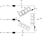
- FIG. 2 depicts a delta topology of an exemplary MMC Statcom
- FIG. 3 depicts a direct topology of a static frequency converter for traction supply
- FIG. 4 depicts a 3-phase to 3-phase direct topology for hydro applications
- FIG. 5 depicts an indirect topology of an exemplary MMC drive application
- FIG. 6 shows a bipolar and a unipolar converter cell
- FIG. 7 is the result of a simulation of an MMC charging event.
- the invention is equally advantageous for all kinds of Modular Multilevel power Converter (MMC) applications.
- the MMC may be used in electric power transmission systems as Static VAR Compensator (Statcom) for static power-factor correction.
- Statcom Static VAR Compensator
- AC-only Statcoms provide reactive power support to an electric power grid by producing or absorbing reactive power.
- MMCs may likewise be used for converting and/or inverting AC current into DC current and/or vice versa, for converting a single or multi-phase current into another single or multi-phase current, in particular for converting AC current of a first frequency into AC current of a second frequency, or for connecting a load or power source with a power grid.
- the invention is of particular interest to those applications with demanding no-load loss requirements, such as Statcom, rail interties with static frequency conversion for traction supply, and for hydro power applications with conversion of variable frequency current to power grid line frequency current.
- FIG. 1 depicts an exemplary MMC set-up.
- a three phase AC power grid 1 is connectable via a main circuit breaker, or converter feeder breaker, 2 to a primary side of a main, or power, transformer 3 .
- a secondary side of the main transformer is connectable, via converter disconnetor 4 , to AC terminals of an MMC 5 .
- a charging unit including an auxiliary power source 6 and a dedicated auxiliary or charging transformer 7 to which the source 6 is connectable, is connectable to the AC terminals of the MMC via a charging switch, or disconnector, 8 .
- Converter disconnector 4 is provided in the supply line between the main transformer 3 and a connection point of the charging unit in order to allow disconnecting the main transformer 3 during charging. The presence of the main transformer and converter disconnector is optional.
- FIG. 2 depicts a delta topology of an exemplary MMC Statcom, with three converter terminals U, V, W.
- the converter terminals coincide with branch terminals, or branch ends, or branch connection points, A, B, C, of the three delta-connected converter branches 10 , 10 ′, 10 ′′, such that the voltage applied to a converter branch is equal to a line-to-line, or phase-to-phase AC voltage of the power grid.
- the branches are shown with four converter cells each, wherein a larger number of forty cells or more per branch is possible.
- a first subset S 1 comprising two converter cells
- a second subset S 2 comprising three converter cells are indicated by dotted and broken rectangles.
- the individual converter cells are of a unipolar or, more preferably, bipolar type as depicted in FIG. 6 below.
- FIG. 3 depicts a direct topology of an exemplary rail intertie, for converting power grid line frequency current at 50 Hz to traction supply current of 162 ⁇ 3 Hz to be injected in the catenary of a railway line.
- FIG. 4 depicts a direct topology of an exemplary variable speed three-phase to three-phase frequency converter for hydro power or bidirectional pumped-hydro power applications, where a variable frequency AC current in phases R, S, T is converted to a line frequency AC current in phases U, V, W, or vice-versa.
- FIG. 5 depicts an indirect topology of an exemplary MMC drive application.
- the indirect AC-AC converter has top and bottom branches forming two parallel wye circuits, with a neutral point of each wye circuit being connected to a respective DC terminal.
- FIG. 6 depicts two exemplary converter cells each with power semiconductor switches and accompanying freewheeling diodes, a cell capacitance 11 , and additional circuitry.
- a unipolar converter cell (left) with two semiconductor switches 12 a , 12 b
- a bipolar cell (right) with four semiconductor switches 13 a to 13 d are shown.
- In the block pulse mode all semiconductor switches are open.
- switch 12 b of the half bridge circuit of the unipolar cell is closed, while for the full bridge circuit of the bipolar cell two possibilities are available, either switches 13 a and 13 c being closed, or switches 13 b and 13 d being closed.
- FIG. 7 is the outcome of a computer simulation of a time evolution of cell voltages during a charging mode operation of an MMC according to the invention.
- the diagram depicts per-unit cell capacitor DC voltages as a function of charging time in seconds, where the lines may actually represent several cells with temporarily overlapping charging profiles.
Landscapes
- Engineering & Computer Science (AREA)
- Power Engineering (AREA)
- Mechanical Engineering (AREA)
- Inverter Devices (AREA)
Abstract
Description
-
- applying a branch voltage to the converter branch, the branch voltage being inferior to a nominal branch voltage cumulative, or corresponding to a total, of the nominal cell voltages of the cells of the branch;
- selecting a first subset of the plurality of converter cells of the branch, and selecting a second subset of the plurality of converter cells of the branch which is distinct from and larger than the first subset;
- operating successively the first and second subset in a firing or gate “pulse blocked” cell operation mode with DC cell voltage increase, and operating a respective complementary subset of the plurality of converter cells of the branch in a “bypass”, or “zero output voltage” cell operation mode without DC cell voltage increase.
Claims (14)
Applications Claiming Priority (4)
| Application Number | Priority Date | Filing Date | Title |
|---|---|---|---|
| EP14197755 | 2014-12-12 | ||
| EP14197755.3 | 2014-12-12 | ||
| EP14197755.3A EP3032680A1 (en) | 2014-12-12 | 2014-12-12 | Standby and charging of modular multilevel converters |
| PCT/EP2015/076257 WO2016091517A1 (en) | 2014-12-12 | 2015-11-10 | Standby and charging of modular multilevel converters |
Related Parent Applications (1)
| Application Number | Title | Priority Date | Filing Date |
|---|---|---|---|
| PCT/EP2015/076257 Continuation WO2016091517A1 (en) | 2014-12-12 | 2015-11-10 | Standby and charging of modular multilevel converters |
Publications (2)
| Publication Number | Publication Date |
|---|---|
| US20170271997A1 US20170271997A1 (en) | 2017-09-21 |
| US10651755B2 true US10651755B2 (en) | 2020-05-12 |
Family
ID=52016526
Family Applications (1)
| Application Number | Title | Priority Date | Filing Date |
|---|---|---|---|
| US15/617,583 Active 2036-06-12 US10651755B2 (en) | 2014-12-12 | 2017-06-08 | Standby and charging of modular multilevel converters |
Country Status (4)
| Country | Link |
|---|---|
| US (1) | US10651755B2 (en) |
| EP (2) | EP3032680A1 (en) |
| CA (1) | CA2968459C (en) |
| WO (1) | WO2016091517A1 (en) |
Families Citing this family (20)
| Publication number | Priority date | Publication date | Assignee | Title |
|---|---|---|---|---|
| GB2541007B (en) * | 2015-08-05 | 2017-12-13 | General Electric Technology Gmbh | Voltage source converter |
| WO2018006970A1 (en) * | 2016-07-07 | 2018-01-11 | Abb Schweiz Ag | Semiconductor power stack of a modular multilevel converter |
| CN107181419A (en) * | 2017-06-06 | 2017-09-19 | 江苏大学 | A kind of Modularized multi-level converter sub-module electric capacity optimizes method for equalizing voltage |
| WO2018229857A1 (en) * | 2017-06-13 | 2018-12-20 | 三菱電機株式会社 | Power conversion system |
| CN107769593B (en) * | 2017-10-17 | 2019-10-08 | 南方电网科学研究院有限责任公司 | Power electronic equipment and control method thereof |
| CN108647447B (en) * | 2018-05-11 | 2022-07-01 | 中电普瑞电力工程有限公司 | Method and device for reliability analysis of MMC converter valve |
| EP3713073A1 (en) * | 2019-03-19 | 2020-09-23 | Siemens Aktiengesellschaft | Converter and method for controlling same |
| WO2021052547A1 (en) * | 2019-09-19 | 2021-03-25 | Vestas Wind Systems A/S | Synchronizing grid side harmonic filter and pre-charging cell capacitors in modular multilevel converters |
| EP4032175A1 (en) * | 2019-09-19 | 2022-07-27 | Vestas Wind Systems A/S | Modular multilevel converter pre-charging |
| CN110880792B (en) * | 2019-11-04 | 2021-03-30 | 中国能源建设集团华东电力试验研究院有限公司 | One-time voltage-on synchronous nuclear phase fast switching inspection system and inspection method for electrical system |
| CN111216602B (en) * | 2020-01-07 | 2021-11-30 | 兰州交通大学 | Method for distributing and optimizing regenerative braking energy in non-contact traction power supply system station |
| EP3866326A1 (en) * | 2020-02-17 | 2021-08-18 | Siemens Aktiengesellschaft | Converter and method for the operation of same |
| CN111181374B (en) * | 2020-02-19 | 2021-06-11 | 南京工程学院 | Starting control method of MMC type multi-port solid-state transformer |
| CN111211677B (en) * | 2020-02-19 | 2021-06-01 | 南京工程学院 | A fast restart method for DC faults of MMC type multi-port solid state transformers |
| JP7615714B2 (en) * | 2020-03-04 | 2025-01-17 | 富士電機株式会社 | Power Conversion Equipment |
| CN114070107B (en) * | 2020-07-31 | 2023-08-08 | 南京南瑞继保电气有限公司 | Charging control method and device for hybrid converter |
| CN112152231B (en) * | 2020-09-08 | 2022-02-01 | 东北电力大学 | Direct-current voltage balance control method for chain-type STATCOM submodule |
| EP4027506A1 (en) * | 2021-01-08 | 2022-07-13 | Siemens Energy Global GmbH & Co. KG | Power converter and method for operating a power converter |
| CN113114049B (en) * | 2021-04-15 | 2022-03-18 | 湖南大学 | Hybrid modular multilevel railway power regulator and control method and system thereof |
| EP4475420A1 (en) * | 2023-06-05 | 2024-12-11 | Siemens Energy Global GmbH & Co. KG | Mmc delta statcom with half-bridge modules connected in anti-series |
Citations (10)
| Publication number | Priority date | Publication date | Assignee | Title |
|---|---|---|---|---|
| US20090140706A1 (en) * | 2007-12-03 | 2009-06-04 | System method and apparatus for a multi-phase dc-to-dc converter | |
| CN103337951A (en) | 2013-06-28 | 2013-10-02 | 中国西电电气股份有限公司 | Method for realizing MMC (Modular Multilevel Converter) redundancy protection strategy based on carrier phase shift modulation |
| US20140002048A1 (en) | 2011-03-21 | 2014-01-02 | China Electric Power Research Institute | Voltage balancing control method for modular multilevel converter |
| WO2014023334A1 (en) | 2012-08-07 | 2014-02-13 | Abb Ab | Method and device for controlling a multilevel converter |
| US20140247629A1 (en) * | 2013-03-01 | 2014-09-04 | Ge Eneygy Power Conversion Technology Limited | Converters |
| US20150078053A1 (en) * | 2013-09-16 | 2015-03-19 | Enphase Energy, Inc. | Single-phase cycloconverter with integrated line-cycle energy storage |
| US20160036314A1 (en) * | 2013-03-18 | 2016-02-04 | Mitsubishi Electric Corporation | Power conversion apparatus |
| US20160056710A1 (en) * | 2013-04-18 | 2016-02-25 | Abb Technology Ltd | Mechanical bypass switch device, converter arm and power converter |
| US9419539B2 (en) * | 2014-08-25 | 2016-08-16 | General Electric Company | Systems and methods for enhanced operation and protection of power converters |
| US20170126127A1 (en) * | 2014-06-30 | 2017-05-04 | Mitsubishi Electric Corporation | Power conversion device |
Family Cites Families (1)
| Publication number | Priority date | Publication date | Assignee | Title |
|---|---|---|---|---|
| US20140000204A1 (en) * | 2011-03-08 | 2014-01-02 | Harbin Wushuhuan Construction Engineering Technology Research Co., Ltd. | Outer thermal insulating composite wall with supporters for outer walls |
-
2014
- 2014-12-12 EP EP14197755.3A patent/EP3032680A1/en not_active Withdrawn
-
2015
- 2015-11-10 CA CA2968459A patent/CA2968459C/en active Active
- 2015-11-10 WO PCT/EP2015/076257 patent/WO2016091517A1/en not_active Ceased
- 2015-11-10 EP EP15793804.4A patent/EP3231053B1/en active Active
-
2017
- 2017-06-08 US US15/617,583 patent/US10651755B2/en active Active
Patent Citations (10)
| Publication number | Priority date | Publication date | Assignee | Title |
|---|---|---|---|---|
| US20090140706A1 (en) * | 2007-12-03 | 2009-06-04 | System method and apparatus for a multi-phase dc-to-dc converter | |
| US20140002048A1 (en) | 2011-03-21 | 2014-01-02 | China Electric Power Research Institute | Voltage balancing control method for modular multilevel converter |
| WO2014023334A1 (en) | 2012-08-07 | 2014-02-13 | Abb Ab | Method and device for controlling a multilevel converter |
| US20140247629A1 (en) * | 2013-03-01 | 2014-09-04 | Ge Eneygy Power Conversion Technology Limited | Converters |
| US20160036314A1 (en) * | 2013-03-18 | 2016-02-04 | Mitsubishi Electric Corporation | Power conversion apparatus |
| US20160056710A1 (en) * | 2013-04-18 | 2016-02-25 | Abb Technology Ltd | Mechanical bypass switch device, converter arm and power converter |
| CN103337951A (en) | 2013-06-28 | 2013-10-02 | 中国西电电气股份有限公司 | Method for realizing MMC (Modular Multilevel Converter) redundancy protection strategy based on carrier phase shift modulation |
| US20150078053A1 (en) * | 2013-09-16 | 2015-03-19 | Enphase Energy, Inc. | Single-phase cycloconverter with integrated line-cycle energy storage |
| US20170126127A1 (en) * | 2014-06-30 | 2017-05-04 | Mitsubishi Electric Corporation | Power conversion device |
| US9419539B2 (en) * | 2014-08-25 | 2016-08-16 | General Electric Company | Systems and methods for enhanced operation and protection of power converters |
Non-Patent Citations (4)
| Title |
|---|
| European Patent Office, Extended Search Report issued in corresponding Application No. 14197755.3, dated Jun. 2, 2015, 6 pp. |
| European Patent Office, International Search Report and Written Opinion issued in corresponding Application No. PCT/EP2015/076257, dated Jan. 27, 2016, 13 pp. |
| Fan et al., "An Improved Control System for Modular Multilevel Converters Featuring New Modulation Strategy and Voltage Balancing Control," 2013 IEEE Energy Conversion Congress and Exposition, Sep. 15, 2013, pp. 4000-4007. |
| Saeedifard et al., "Dynamic Performance of a Modular Multilevel Back-to-Back HVDC System," IEEE Transactions on Power Delivery, vol. 25, No. 4, Oct. 2010, pp. 2903-2912. |
Also Published As
| Publication number | Publication date |
|---|---|
| WO2016091517A1 (en) | 2016-06-16 |
| EP3231053A1 (en) | 2017-10-18 |
| EP3231053B1 (en) | 2019-07-24 |
| EP3032680A1 (en) | 2016-06-15 |
| CA2968459A1 (en) | 2016-06-16 |
| CA2968459C (en) | 2023-04-04 |
| US20170271997A1 (en) | 2017-09-21 |
Similar Documents
| Publication | Publication Date | Title |
|---|---|---|
| US10651755B2 (en) | Standby and charging of modular multilevel converters | |
| US9748848B2 (en) | Modular multilevel DC/DC converter for HVDC applications | |
| KR101797796B1 (en) | Hvdc converter comprising fullbridge cells for handling a dc side short circuit | |
| EP3391522B1 (en) | Voltage balancing in a modular multilevel converter having delta configuration | |
| EP2494687B1 (en) | High voltage ac-dc converter | |
| CN105191108B (en) | Converter | |
| EP2671310B1 (en) | Power electronic converter | |
| EP2988404A1 (en) | Modular multilevel converter precharge | |
| US9847737B2 (en) | Modular multilevel converter leg with flat-top PWM modulation, converter and hybrid converter topologies | |
| WO2012041380A1 (en) | Modular converter with reduced protection requirements that prevents damage to components by extinguishing fault currents. | |
| Bordignon et al. | Modular multilevel converter in HVDC systems under fault conditions | |
| US10305274B2 (en) | Pre-magnetizing a transformer connected to a modular multilevel power converter | |
| EP3142239A1 (en) | Precharging of a modular multilevel converter | |
| CN108604797B (en) | Multilevel power converter and method for controlling a multilevel power converter | |
| WO2021105455A1 (en) | Modular multilvel converter | |
| EP3512088B1 (en) | Voltage source converter | |
| Keshavarzian et al. | A new strategy for control of cascaded H-bridge rectifiers with uneqaul loads |
Legal Events
| Date | Code | Title | Description |
|---|---|---|---|
| AS | Assignment |
Owner name: ABB SCHWEIZ AG, SWITZERLAND Free format text: ASSIGNMENT OF ASSIGNORS INTEREST;ASSIGNORS:HEROLD, SIMON;BUCHMANN, BEAT;REEL/FRAME:043726/0450 Effective date: 20170703 |
|
| STPP | Information on status: patent application and granting procedure in general |
Free format text: DOCKETED NEW CASE - READY FOR EXAMINATION |
|
| STPP | Information on status: patent application and granting procedure in general |
Free format text: NON FINAL ACTION MAILED |
|
| STPP | Information on status: patent application and granting procedure in general |
Free format text: RESPONSE TO NON-FINAL OFFICE ACTION ENTERED AND FORWARDED TO EXAMINER |
|
| STPP | Information on status: patent application and granting procedure in general |
Free format text: NOTICE OF ALLOWANCE MAILED -- APPLICATION RECEIVED IN OFFICE OF PUBLICATIONS |
|
| STCF | Information on status: patent grant |
Free format text: PATENTED CASE |
|
| AS | Assignment |
Owner name: ABB POWER GRIDS SWITZERLAND AG, SWITZERLAND Free format text: ASSIGNMENT OF ASSIGNORS INTEREST;ASSIGNOR:ABB SCHWEIZ AG;REEL/FRAME:055589/0769 Effective date: 20201202 Owner name: ABB POWER GRIDS SWITZERLAND AG, SWITZERLAND Free format text: ASSIGNMENT OF ASSIGNOR'S INTEREST;ASSIGNOR:ABB SCHWEIZ AG;REEL/FRAME:055589/0769 Effective date: 20201202 |
|
| AS | Assignment |
Owner name: HITACHI ENERGY SWITZERLAND AG, SWITZERLAND Free format text: CHANGE OF NAME;ASSIGNOR:ABB POWER GRIDS SWITZERLAND AG;REEL/FRAME:058666/0540 Effective date: 20211006 |
|
| MAFP | Maintenance fee payment |
Free format text: PAYMENT OF MAINTENANCE FEE, 4TH YEAR, LARGE ENTITY (ORIGINAL EVENT CODE: M1551); ENTITY STATUS OF PATENT OWNER: LARGE ENTITY Year of fee payment: 4 |
|
| AS | Assignment |
Owner name: HITACHI ENERGY LTD, SWITZERLAND Free format text: MERGER;ASSIGNOR:HITACHI ENERGY SWITZERLAND AG;REEL/FRAME:065549/0576 Effective date: 20231002 |