US10647040B2 - Co-injection nozzle comprising integrated back-flow barrier - Google Patents
Co-injection nozzle comprising integrated back-flow barrier Download PDFInfo
- Publication number
- US10647040B2 US10647040B2 US15/524,795 US201515524795A US10647040B2 US 10647040 B2 US10647040 B2 US 10647040B2 US 201515524795 A US201515524795 A US 201515524795A US 10647040 B2 US10647040 B2 US 10647040B2
- Authority
- US
- United States
- Prior art keywords
- melt
- channel
- injection nozzle
- nozzle
- injection
- Prior art date
- Legal status (The legal status is an assumption and is not a legal conclusion. Google has not performed a legal analysis and makes no representation as to the accuracy of the status listed.)
- Active, expires
Links
Images


Classifications
-
- B—PERFORMING OPERATIONS; TRANSPORTING
- B29—WORKING OF PLASTICS; WORKING OF SUBSTANCES IN A PLASTIC STATE IN GENERAL
- B29C—SHAPING OR JOINING OF PLASTICS; SHAPING OF MATERIAL IN A PLASTIC STATE, NOT OTHERWISE PROVIDED FOR; AFTER-TREATMENT OF THE SHAPED PRODUCTS, e.g. REPAIRING
- B29C45/00—Injection moulding, i.e. forcing the required volume of moulding material through a nozzle into a closed mould; Apparatus therefor
- B29C45/17—Component parts, details or accessories; Auxiliary operations
- B29C45/20—Injection nozzles
-
- B—PERFORMING OPERATIONS; TRANSPORTING
- B29—WORKING OF PLASTICS; WORKING OF SUBSTANCES IN A PLASTIC STATE IN GENERAL
- B29C—SHAPING OR JOINING OF PLASTICS; SHAPING OF MATERIAL IN A PLASTIC STATE, NOT OTHERWISE PROVIDED FOR; AFTER-TREATMENT OF THE SHAPED PRODUCTS, e.g. REPAIRING
- B29C45/00—Injection moulding, i.e. forcing the required volume of moulding material through a nozzle into a closed mould; Apparatus therefor
- B29C45/16—Making multilayered or multicoloured articles
- B29C45/1603—Multi-way nozzles specially adapted therefor
-
- B—PERFORMING OPERATIONS; TRANSPORTING
- B29—WORKING OF PLASTICS; WORKING OF SUBSTANCES IN A PLASTIC STATE IN GENERAL
- B29C—SHAPING OR JOINING OF PLASTICS; SHAPING OF MATERIAL IN A PLASTIC STATE, NOT OTHERWISE PROVIDED FOR; AFTER-TREATMENT OF THE SHAPED PRODUCTS, e.g. REPAIRING
- B29C45/00—Injection moulding, i.e. forcing the required volume of moulding material through a nozzle into a closed mould; Apparatus therefor
- B29C45/17—Component parts, details or accessories; Auxiliary operations
- B29C45/20—Injection nozzles
- B29C45/23—Feed stopping equipment
- B29C45/231—Needle valve systems therefor
-
- B—PERFORMING OPERATIONS; TRANSPORTING
- B29—WORKING OF PLASTICS; WORKING OF SUBSTANCES IN A PLASTIC STATE IN GENERAL
- B29C—SHAPING OR JOINING OF PLASTICS; SHAPING OF MATERIAL IN A PLASTIC STATE, NOT OTHERWISE PROVIDED FOR; AFTER-TREATMENT OF THE SHAPED PRODUCTS, e.g. REPAIRING
- B29C45/00—Injection moulding, i.e. forcing the required volume of moulding material through a nozzle into a closed mould; Apparatus therefor
- B29C45/03—Injection moulding apparatus
- B29C45/13—Injection moulding apparatus using two or more injection units co-operating with a single mould
-
- B—PERFORMING OPERATIONS; TRANSPORTING
- B29—WORKING OF PLASTICS; WORKING OF SUBSTANCES IN A PLASTIC STATE IN GENERAL
- B29C—SHAPING OR JOINING OF PLASTICS; SHAPING OF MATERIAL IN A PLASTIC STATE, NOT OTHERWISE PROVIDED FOR; AFTER-TREATMENT OF THE SHAPED PRODUCTS, e.g. REPAIRING
- B29C45/00—Injection moulding, i.e. forcing the required volume of moulding material through a nozzle into a closed mould; Apparatus therefor
- B29C45/16—Making multilayered or multicoloured articles
- B29C45/1642—Making multilayered or multicoloured articles having a "sandwich" structure
- B29C45/1646—Injecting parison-like articles
- B29C2045/1648—Injecting parison-like articles the parison core layer being a barrier material
-
- B—PERFORMING OPERATIONS; TRANSPORTING
- B29—WORKING OF PLASTICS; WORKING OF SUBSTANCES IN A PLASTIC STATE IN GENERAL
- B29C—SHAPING OR JOINING OF PLASTICS; SHAPING OF MATERIAL IN A PLASTIC STATE, NOT OTHERWISE PROVIDED FOR; AFTER-TREATMENT OF THE SHAPED PRODUCTS, e.g. REPAIRING
- B29C45/00—Injection moulding, i.e. forcing the required volume of moulding material through a nozzle into a closed mould; Apparatus therefor
- B29C45/17—Component parts, details or accessories; Auxiliary operations
- B29C45/20—Injection nozzles
- B29C2045/205—Elongated nozzle openings
-
- B—PERFORMING OPERATIONS; TRANSPORTING
- B29—WORKING OF PLASTICS; WORKING OF SUBSTANCES IN A PLASTIC STATE IN GENERAL
- B29C—SHAPING OR JOINING OF PLASTICS; SHAPING OF MATERIAL IN A PLASTIC STATE, NOT OTHERWISE PROVIDED FOR; AFTER-TREATMENT OF THE SHAPED PRODUCTS, e.g. REPAIRING
- B29C45/00—Injection moulding, i.e. forcing the required volume of moulding material through a nozzle into a closed mould; Apparatus therefor
- B29C45/16—Making multilayered or multicoloured articles
- B29C45/1603—Multi-way nozzles specially adapted therefor
- B29C45/1607—Multi-way nozzles specially adapted therefor having at least three different ways
-
- B—PERFORMING OPERATIONS; TRANSPORTING
- B29—WORKING OF PLASTICS; WORKING OF SUBSTANCES IN A PLASTIC STATE IN GENERAL
- B29K—INDEXING SCHEME ASSOCIATED WITH SUBCLASSES B29B, B29C OR B29D, RELATING TO MOULDING MATERIALS OR TO MATERIALS FOR MOULDS, REINFORCEMENTS, FILLERS OR PREFORMED PARTS, e.g. INSERTS
- B29K2995/00—Properties of moulding materials, reinforcements, fillers, preformed parts or moulds
- B29K2995/0037—Other properties
- B29K2995/0065—Permeability to gases
- B29K2995/0067—Permeability to gases non-permeable
-
- B—PERFORMING OPERATIONS; TRANSPORTING
- B29—WORKING OF PLASTICS; WORKING OF SUBSTANCES IN A PLASTIC STATE IN GENERAL
- B29L—INDEXING SCHEME ASSOCIATED WITH SUBCLASS B29C, RELATING TO PARTICULAR ARTICLES
- B29L2031/00—Other particular articles
- B29L2031/712—Containers; Packaging elements or accessories, Packages
- B29L2031/7148—Blood bags, medical bags
Definitions
- the invention relates to a co-injection nozzle for a hot runner co-injection device of an injection moulding apparatus for the production of multilayer injection moulded products, in particular injection moulded products with a barrier or sealing layer.
- Co-injection nozzles of this type comprise an annular inner melt channel which, in the downstream half of the co-injection nozzle, is formed by the central bore and the valve needle and is in fluid communication with a first melt supply channel; an annular middle melt channel which is in fluid communication with a second melt supply channel and which extends about the annular inner melt channel; and an annular outer melt channel which is in fluid communication with the first melt supply channel and which extends about the annular middle melt channel.
- the inner, middle and outer melt channels are fluidically merged in the region of the nozzle tip in order to form a concentrically layered melt stream.
- Co-injection nozzles or hot runner co-injection devices for injection moulding apparatus with which two different melts can be simultaneously injected through a nozzle orifice into a moulding chamber or cavity of an injection mould, have been known for a long time (for example U.S. Pat. No. 4,657,496).
- Most older co-injection nozzles have two separate channels for the two melts, which are disposed in a manner such that a two-layered stream of melt is discharged from the nozzle orifice.
- a special type of co-injection nozzle is actually used in which the outflow stream is triple-layered and concentrically configured, wherein the barrier layer forms the middle layer.
- WO 81/00231 discloses a co-injection nozzle of this type, which combines three separate melt streams in one triple-layered, concentric melt outflow stream.
- the inner melt stream can be regulated using a valve needle disposed in a central bore of the nozzle.
- a first melt is divided into two streams outside or inside the co-injection nozzle which then form an inner and outer layer of the concentric outflow stream.
- a second melt is guided between the two layers and forms the middle barrier layer.
- the three layers are then combined into a multilayer melt stream outside or inside the co-injection nozzle and then injected into the mould cavity as a concentric outflow stream, whereupon a multilayer injection moulded product is formed with a barrier layer that is covered on both sides.
- the melts of the various layers can be regulated as a function of the type of embodiment of the co-injection nozzle or the co-injection device. In order to enclose the barrier layer completely in the melt for the outer and inner layer, at the respective start and end of an injection moulding procedure, only the melt for the outer and/or the inner layer is injected, without the melt for the middle layer.
- EP 0 929 390 discloses a co-injection nozzle in which the three melt layers are combined in a combination unit disposed upstream of the nozzle and then guided along an elongate tubular flow channel to the nozzle orifice.
- the tubular flow channel is formed by a central bore in the nozzle body and a valve needle disposed therein.
- the valve needle can be used to adjust the flow of the inner melt layer in the combination unit.
- the flow of the individual melt streams is regulated via the supply unit.
- EP 0 911 134 describes a co-injection unit in which three melt streams are guided through a respective melt supply opening into the co-injection nozzle and are combined to form a concentrically layered melt stream in the nozzle tip region shortly before the nozzle orifice.
- the melt for the inner layer is guided in an annular inner melt channel which is formed by a central bore and a valve needle.
- the melt for the middle layer is guided in an annular middle melt channel which extends about the annular inner melt channel.
- the melt for the outer layer is guided in an annular outer melt channel which extends about the annular middle melt channel.
- the inner and middle melt channels can be closed off by the valve needle while the outer melt channel remains open.
- WO 00/54955 discloses a co-injection nozzle in which the two melts for the inner and middle layer are combined in a first upstream combination unit outside the co-injection nozzle and then guided together along an inner central melt channel to the nozzle orifice in order to obtain a combined melt stream which is as stable as possible.
- the melt for the outer layer is combined with the already combined central melt stream and then injected like this into the mould cavity.
- WO 04/103668 discloses a co-injection device in which a first melt stream is divided within a co-injection nozzle into two streams for the inner and outer layer. The divided streams are combined in a combination chamber with the second melt for the middle layer upstream of an elongate central melt channel in order to form a concentrically layered melt stream which then is guided via the central melt channel along a valve needle to the nozzle orifice.
- the combination chamber is thus configured in a manner such that the formation of the middle layer can be regulated with a minimum amount of material from the two streams of the first melt, avoiding instabilities in the flow.
- EP 2 054 209 discloses a co-injection device in which a first melt is divided into two streams upstream of the inlet into the co-injection nozzle. The divided streams are then merged with the second melt in the region of the nozzle tip in order to form a multilayer melt stream.
- WO 11/006999 describes a co-injection device in which two melts are supplied laterally of a co-injection nozzle, wherein the first melt is divided within the co-injection nozzle into a stream for the inner and outer layer respectively. The streams are combined in the nozzle tip.
- the co-injection nozzle has a movable needle and a movable sleeve to regulate the individual melt streams.
- WO 12/037682 discloses a co-injection nozzle in which a portion of a first melt stream is guided through an annular second melt stream via lateral tunnel channels. The three melt streams are combined in the region of the tip to form a multilayer melt stream. The inflow of the middle melt stream can be regulated with a movable sleeve.
- the material for the barrier layer is expensive, and so in multilayer injection moulded products, it is preferably present in a layer which is as thin as possible. Furthermore, at the start and end of the respective injection moulding cycle, only the first melt is injected and the melt stream for the second melt, which forms the barrier layer, is interrupted in order to obtain an injection moulded product with a completely encapsulated barrier layer. Precise regulation of the second melt is thus desirable in order to produce injection moulded products with very thin barrier layers.
- co-injection devices such as those known from WO 00/54955 or EP 0 901 896, have a back-flow control valve which is disposed outside the co-injection nozzle.
- EP 0 901 896 in fact concerns a co-injection nozzle with a concentric melt outflow stream with only two layers, wherein back-flow is not so serious, because it is not suitable for the production of injection moulded products with a barrier layer.
- the back-flow control valve is disposed upstream of the co-injection nozzle in a combination unit between a front melt manifold plate for the first melt and a rear melt manifold plate for the second melt.
- An object of the invention is to provide a simple and compactly constructed co-injection nozzle for the production of multilayer injection moulded products with a barrier layer, wherein back-flow of the melt for the barrier layer is prevented and which can be produced and maintained inexpensively.
- the co-injection nozzle for an injection moulding apparatus for the production of multilayer injection moulded products comprises a first melt supply channel for a first melt and a second melt supply channel for a second melt.
- the two melt supply channels can simply be connected to a supply device for the respective first and second melts.
- the co-injection nozzle comprises a central bore; an axially movable valve needle accommodated in the central bore to open and close a nozzle orifice; an annular inner melt channel which is formed in the downstream half of the co-injection nozzle by the central bore and the valve needle and is in fluid communication with the first melt supply channel; an annular middle melt channel which is in fluid communication with the second melt supply channel and which extends about the annular inner melt channel; and an annular outer melt channel which is in fluid communication with the first melt supply channel and which extends about the annular middle melt channel.
- the inner, middle and outer melt channels converge fluidically in the region of the nozzle tip in order to form a concentrically layered melt stream.
- the co-injection nozzle furthermore comprises a back-flow barrier for the second melt integrated into the central bore which is formed by a recess in the valve needle and a melt channel for the second melt traversing the central bore, wherein in an open position of the back-flow barrier, the recess is disposed with respect to the traversing melt channel in a manner such that the second melt can flow through the traversing melt channel inasmuch as it can flow in the central bore past the valve needle.
- the second melt which is guided in the channel traversing the central bore after being supplied to the co-injection nozzle, can thus flow through the traversing melt channel or not flow through it, as a function of the position of the movable valve needle—which also serves to open and close the nozzle orifice.
- the valve needle which is already present in the co-injection nozzle is also used as the back-flow barrier. In this manner, the construction of the co-injection nozzle or co-injection device is simpler and more compact compared with the prior art.
- the recess and the traversing melt channel are disposed with respect to each other in a manner such that in a first position, the valve needle closes off the nozzle orifice and the traversing melt channel, in a second position it opens the nozzle orifice with the traversing melt channel being closed, and in a third position it opens both the nozzle orifice and the traversing melt channel.
- the first position neither of the two melts can flow.
- the second position only the first melt can flow and the flow of the second melt is blocked. In this manner, back-flow of the second melt is efficiently prevented by back-pressure of the first melt into the middle melt channel.
- the first and the second melts can flow to the nozzle orifice.
- the recess may be in the form of a constriction, a cross-bore or a circumferential or oblique groove.
- the melt channel traversing the central bore places the second melt supply channel in fluid communication with the annular middle channel for the second melt.
- the traversing melt channel is disposed in the upstream half of the co-injection nozzle, i.e. upstream of the annular inner melt channel.
- the melt channel traversing the central bore preferably has an incoming melt channel and at least one outgoing melt channel.
- the incoming melt channel is in fluid communication with the second melt supply channel.
- the at least one outgoing melt channel is in fluid communication with the annular middle melt channel.
- the traversing melt channel in the distribution insert is formed by at least one through bore or by a plurality of bores which open laterally into the central bore. The openings of the incoming melt channel and the at least one outgoing melt channel into the central bore may be disposed at approximately the same height in the axial direction.
- the co-injection nozzle comprises a nozzle body with a central bore, in which a cylindrical distribution insert of the co-injection nozzle which is provided with the central bore of the co-injection nozzle is accommodated.
- the traversing melt channel is located in the distribution insert and is formed by at least one through bore or by a plurality of bores opening into the central bore.
- the traversing melt channel is formed by an incoming melt channel and two outgoing melt channels, wherein the incoming melt channel is in fluid communication with the second melt supply channel and the two outgoing melt channels are in fluid communication with the annular middle melt channel via a respective distribution channel.
- the distribution channels may be formed as grooves incorporated into the surface of the melt distribution insert. This is also possible with just one outgoing melt channel and one distribution channel.
- the invention further concerns a co-injection device with at least one co-injection nozzle as described above.
- the co-injection nozzle is held in a nozzle holder plate and accommodated with its tip in a recess of a mould plate.
- regions of the recess in the mould plate may define the annular outer melt channel, wherein the nozzle orifice is formed in the mould plate.
- the co-injection device may have a melt manifold plate with a first melt supply line and a second melt supply line, wherein the first melt supply channel of the co-injection nozzle is connected to the first melt supply line and the second melt supply channel of the co-injection nozzle is connected to the second melt supply line.
- valve needle of the co-injection nozzle extends in a contact-free manner through a bore in the melt manifold plate and is connected at its upstream end to a valve needle actuation device.
- FIG. 1 shows a sectional view of a co-injection device with a co-injection nozzle in an overall view in an injection moulding mould;
- FIG. 2 shows an enlarged detailed view of the co-injection nozzle of FIG. 1 ;
- FIG. 3 shows an exploded view of a co-injection nozzle
- FIG. 4 shows a sectional view of a co-injection nozzle without a valve needle
- FIG. 5 shows a sectional view of the back-flow barrier
- FIGS. 6 ( a ) to ( d ) shows four side views of parts of the co-injection nozzle, in an exploded view
- FIGS. 7 ( a ) and ( b ) respectively show a sectional view of parts of the co-injection nozzle, in an exploded view
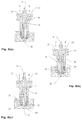
- FIGS. 8 ( a ) to ( c ) respectively show a sectional view of the co-injection nozzle with three different positions of the valve needle.
- FIG. 1 shows a sectional view of a hot runner co-injection device for the production of multilayer injection moulded products provided with a barrier layer.
- the co-injection device comprises a mould plate 1 with a recess for a tip 9 of a co-injection nozzle 2 .
- the co-injection nozzle 2 is held in a nozzle holding plate 3 .
- the co-injection nozzle 2 is provided with a first melt supply opening 21 a to supply a first melt A through a first melt supply line 7 and a second melt supply opening 22 a to supply a second melt B through a second melt supply line 8 .
- a melt manifold plate 4 is accommodated in the nozzle holding plate 3 , which distributes the melts A, B to various co-injection nozzles 2 by means of first and second melt supply lines 7 , 8 ; here, only one co-injection nozzle has been illustrated.
- a back plate 5 is provided to accommodate the valve needle actuation device 6 for a respective valve needle 10 of the co-injection nozzle 2 .
- FIG. 2 shows a detailed view of the co-injection nozzle 2 of FIG. 1 (circle D).
- the co-injection nozzle 2 comprises four concentrically interengaging parts: a nozzle body 11 , a melt distribution insert 12 , a separating sleeve 13 , and a retaining and sealing sleeve 14 .
- the four-part construction (or five-part including the valve needle 10 ) can also be seen in the exploded view of FIG. 3 .
- the nozzle body 11 may be provided with a heating element 15 .
- the co-injection nozzle 2 has a central bore 20 which extends axially through the melt distribution insert 12 , and in which the valve needle 10 is movably accommodated.
- a lower section 20 a i.e. the downstream half 2 a of the co-injection nozzle 2
- the central bore 20 has a larger diameter than in the upper region 20 b (i.e. in the upstream half 2 b of the co-injection nozzle 2 ), so that an annular inner melt channel 23 is formed along the valve needle 10 .
- the valve needle 10 may also be tapered in this region, in order to increase the cross-section of the annular inner melt channel 23 .
- only the valve needle may be tapered in configuration; the central bore would then have the same diameter over its entire length.
- the annular inner melt channel 23 is in fluid communication with a first melt supply channel 21 for the first melt A.
- a nozzle orifice 30 it is in fluid communication with a nozzle orifice 30 .
- the inner melt channel 23 is tapered in the region of a conically converging tip of the melt distribution insert 12 , so that it can be closed by means of the valve needle 10 .
- a melt distribution insert 12 formed in one piece it may be provided with a screwed-on or firmly welded conical tip.
- the melt manifold plate 4 is provided with a bore 4 a through which the valve needle 10 extends further, right up to the valve needle actuation device 6 .
- the diameter of the bore 4 a of the melt manifold plate 4 which is upstream of the co-injection nozzle 2 is larger than the diameter of the central bore 20 in the upper region 20 b , so that the valve needle 10 can be guided in a contact-free manner through the melt manifold plate 4 in order to reduce the conduction of heat via the valve needle 10 into the melt manifold plate 4 and the back plate 5 .
- the first melt supply channel 21 for the first melt A is connected to the first melt supply line 7 of the co-injection device.
- a second melt supply channel 22 for the second melt B is connected to the second melt supply line 8 of the co-injection device.
- the first and second melt supply channels 21 , 22 are straight and are formed by bores in the nozzle body 11 and in the melt distribution insert 12 .
- the first melt supply channel 21 for the melt A leads from a first melt supply opening 21 a on the upper side of the melt distribution insert 12 to the annular inner melt channel 24 .
- At least one distribution channel 26 (not shown in FIGS. 1 and 2 ; see FIGS. 3 and 6 ) for the melt A is in fluid communication with the first melt supply channel 21 and an annular outer channel 25 , so that a melt stream A is divided into two streams which are respectively fed into the annular inner melt channel 24 and into the annular outer melt channel 25 .
- These two divided streams of melt form the inner and outer layers of a concentrically layered melt stream which finally passes through the nozzle orifice 30 into a mould cavity 1 a of the mould plate 1 .
- the second melt supply channel 22 for the melt B leads from a second melt supply opening 22 a on the upper side of the melt distribution insert 12 to a melt channel 41 traversing the central bore 20 which, together with the valve needle 10 , forms a back-flow barrier 40 for the second melt B which is integrated into the central bore 20 .
- the movable valve needle 10 in the illustrated co-injection nozzle 2 has a recess 42 in the form of a circumferential groove or constriction. The stream of melt through the traversing melt channel 41 is blocked as a function of the position of the valve needle 10 .
- the recess 42 is orientated so as to be in communication with the traversing melt channel 41 , so that the melt B can flow round the valve needle 10 in the central bore 20 .
- the traversing melt channel 41 is completely closed off by the valve needle 10 .
- the traversing melt channel 41 is in downstream fluid communication, via at least one distribution channel 27 (not shown in FIGS. 1 and 2 ; see FIGS. 3 and 6 ), with an annular middle melt channel 24 which extends between the annular inner melt channel 23 and the annular outer melt channel 25 .
- the recess 42 and the traversing melt channel 41 are therefore disposed relative to each other in a manner such that in a first position, the valve needle 10 closes off the nozzle orifice 30 and the traversing melt channel 41 (see FIG. 8( a ) ), in a second position the nozzle orifice 30 is open, while the traversing melt channel 41 is closed (see FIG. 8( b ) ), and in a third position both the nozzle orifice 30 and the traversing melt channel 41 are open (see FIG. 8( c ) ).
- the first position neither of the two melts A, B can flow.
- the second position only the first melt A can flow and the flow of the second melt B is blocked.
- a back-flow of the second melt B is efficiently prevented by back-pressure of the first melt A into the middle melt channel 24 .
- the first and the second melts A, B can flow to the nozzle orifice 30 .
- the recess 42 may be in the form of a constriction, a cross-bore or a circumferential or oblique groove.
- the co-injection nozzle 2 is provided with the separating sleeve 13 which, in the co-injection nozzle 2 shown, converges conically in the downstream direction.
- the inwardly orientated surface forms a portion of the middle melt channel 24
- the outwardly orientated surface 25 a forms a portion of the outer melt channel 25 .
- the inner melt channel 24 is also formed by a portion of the outer surface 24 a of the melt distribution insert 12 .
- the outer melt channel 25 is formed by a portion of an inner surface of the retaining and sealing sleeve 14 which on the one hand fixes the separating sleeve 13 in the co-injection nozzle 2 , and on the other hand seals the tip 9 of the co-injection nozzle 2 against the recess in the mould plate 1 , so that the tip 9 of the co-injection nozzle 2 or the outer surface 25 a of the separating sleeve 13 and a portion of the recess of the mould plate 1 form a front melt chamber or respectively a portion of the annular outer melt channel 25 .
- the annular inner, middle and outer melt channels 23 , 24 , 25 converge in order to form a concentrically layered stream of melt which can finally be discharged through the nozzle orifice 30 into the mould cavity 1 a of the mould plate 1 .
- the nozzle orifice 30 can be opened or respectively closed with the movable valve needle 10 , which is provided with a tapering tip in the embodiment shown.
- the mould plate 1 together with the nozzle tip 9 of the co-injection nozzle 2 thus form a kind of front nozzle chamber from which the melts A, B exit through the nozzle orifice 30 , which latter can be closed by the valve needle, into a mould cavity 1 a of the mould plate 1 .
- FIG. 3 shows an exploded view of the co-injection nozzle 2 comprising the five components: valve needle 10 (only the front region which is in the co-injection nozzle is shown), nozzle body 11 , melt distribution insert 12 , separating sleeve 13 and retaining and sealing sleeve 14 .
- FIG. 4 shows a sectional view of the co-injection nozzle 2 of FIG. 3 in the assembled form without the valve needle and with a mould plate 1 shown in diagrammatic form.
- the valve needle 10 ( FIG. 3 ) is provided with a front tapering section (in the downstream half 2 a ) which, together with the central bore 20 in the melt distribution insert 12 , forms the annular inner melt channel 23 . Upstream (in the region of the half 2 b ), the valve needle 10 has a circumferential groove or constriction 42 .
- the melt distribution insert 12 with the central bore 20 has an upstream flange 50 with the first melt supply opening 21 a and the second melt supply opening 22 a . These openings form the inlet respectively to the first and second melt supply channels 21 , 22 .
- a rod-shaped or circular cylinder-shaped section 51 of the melt distribution insert 12 downstream of the flange 50 is accommodated in a central bore 52 of the nozzle body 11 .
- distribution channels 26 , 27 are formed for the melts A, B which place the melt supply channels 21 , 22 in fluid communication with the annular outer and annular middle melt channels 25 , 24 .
- the distribution channels 26 , 27 in this regard are partially closed by the inner wall of the central bore 52 in the nozzle body 11 .
- an incoming melt channel 41 a In the upper region of the section 51 of the melt distribution insert 12 is an incoming melt channel 41 a and one of the two outgoing melt channels 41 b of the melt channel 41 traversing the central bore 20 .
- the incoming melt channel 41 a is in fluid communication with the second melt supply channel 22 .
- the outgoing melt channels 41 b are respectively in fluid communication with the annular middle melt channel 24 via a distribution channel 27 .
- the distribution channels 26 , 27 have a spiral shape in the axial direction, which allows the respective melts to enter the annular outer or inner melt channels 25 , 24 at an inclination with respect to the axial direction, in order to obtain better distribution of the melt (see also FIG. 6 ).
- FIG. 5 shows a detailed sectional view of the integrated back-flow barrier 40 .
- the melt channel 41 traversing the central bore 20 is formed by an incoming melt channel 41 a and two outgoing melt channels 41 b . These are formed by lateral bores in the rod-shaped or circular cylinder-shaped section 51 of the melt distribution insert 12 which reach right into the central bore 20 .
- the bore in the nozzle body 11 for the second melt supply channel 22 reaches right to the bore for the incoming melt channel 41 a .
- the valve needle 10 with the recess 42 is axially movably accommodated in the central bore 20 .
- the back-flow barrier in FIG. 5 is shown in the open position, and the melt B can pass unhindered through the back-flow barrier.
- a conical tip of the rod-shaped section 51 of the melt distribution insert 12 is accommodated herein at a distance from the conical separating sleeve 13 .
- the tip of the conical separating sleeve 13 is accommodated herein, at a distance from the retaining and sealing sleeve 14 .
- the retaining and sealing sleeve 14 has been screwed firmly into the nozzle body 11 and thus holds the separating sleeve 13 in the co-injection nozzle 2 .
- the separating sleeve 13 may be provided with a flange at its upstream end.
- the melt distribution insert 12 is screwed onto the nozzle body 11 via its flange 50 . To clean the co-injection nozzle 2 , this can easily be removed from the nozzle holding plate 3 and the mould plate 1 and be broken down into its individual parts.
- a particular advantage of the construction of the co-injection nozzle with the melt distribution insert described lies in the fact that the integrated back-flow barrier and the distribution of the two melts within the co-injection nozzle can easily be obtained by a few bores and milled grooves in the melt distribution insert.
- the separating sleeve 13 is provided with an opening 13 a the diameter of which corresponds to the diameter of the tapered valve needle 10 .
- the valve needle 10 can take a position in which the fluid communication of the annular inner and middle melt channels 23 , 24 with the nozzle orifice 30 is interrupted.
- the opening 13 a may also, however, have the same diameter as the lower section 20 a of the central bore 20 .
- FIG. 6 shows four side views: FIGS. 6( a ) to 6( d ) (front, right, back, left) of the melt distribution insert 12 and the separating sleeve 13 in an exploded view, wherein the views are respectively rotated by 90°.
- FIG. 7( a ) (right, see FIG. 6( b ) ) and FIG. 7( b ) (front, see FIG. 6( a ) ) respectively show a sectional view of the melt distribution insert 12 and the separation sleeve 13 in an exploded view.
- the spiral shape of the distribution channels 26 , 27 can be seen particularly well in FIG. 6 .
- two distribution channels 26 , 27 are respectively formed.
- the two distribution channels 26 for the first melt A and the two distribution channels 27 for the second melt B alternate and are at a uniform distance from each other around the circumference of the circular cylinder-shaped section 51 , allowing for optimized distribution of heat within the co-injection nozzle 2 .
- the distribution channels may also be formed so as to run straight in the axial direction.
- the incoming melt channel 41 a of the back-flow barrier can be seen in FIG. 6( b ) .
- the second melt B is divided into two streams which pass through the outgoing melt channels 41 b ( FIGS. 6( a ) and 6( c ) ) into the respective distribution channels 27 .
- the first melt supply channel 21 reaches right up to the central bore 20 of the melt distribution insert 12 ( FIG. 7( b ) ). In this region, a portion of the melt A is guided laterally in two distribution channels 26 on the surface of the melt distribution insert 12 and a portion is guided into the annular inner melt channel 23 along the lower section 20 a of the central bore 20 .
- the first distribution channel 26 is fed directly through the first melt supply channel 21 .
- a connecting channel 28 connects the second distribution channel 26 to the central bore 20 , and thus is supplied with the first melt A.
- the distribution channels 27 start upstream of the distribution channels 26 and extend further downstream than the distribution channels 26 , into the region of the annular middle melt channel 24 part of which is formed by the surface 4 a of the conical tip of the melt distribution insert 12 .
- the distribution channels 26 for the first melt A are thus shorter in length than the distribution channels 27 for the second melt B.
- the annular outer melt channel 25 extends in the axial direction further upstream than the annular middle melt channel 24 .
- the distribution channel 26 can feed the annular outer melt channel 25 through a bore 26 a in the separating sleeve 13 without having to traverse the middle melt channel 24 .
- This bore 26 a ends in the outer surface 25 a of the separating sleeve 13 , which forms part of the annular outer melt channel 25 .
Landscapes
- Engineering & Computer Science (AREA)
- Manufacturing & Machinery (AREA)
- Mechanical Engineering (AREA)
- Injection Moulding Of Plastics Or The Like (AREA)
- Moulds For Moulding Plastics Or The Like (AREA)
- Nozzles (AREA)
Abstract
Description
- 1 mould plate
- 1 a mould chamber (cavity)
- 2 co-injection nozzle
- 2 a half of co-injection nozzle (downstream)
- 2 b half of co-injection nozzle (upstream)
- 3 nozzle holding plate
- 4 melt manifold plate
- 4 a bore
- 5 back plate
- 6 valve needle actuation device
- 7 first melt supply line
- 8 second melt supply line
- 9 nozzle tip
- 10 valve needle
- 11 nozzle body
- 12 melt distribution insert
- 13 separating sleeve
- 14 retaining and sealing sleeve
- 15 heating element
- 20 central bore
- 20 a lower section of central bore
- 20 b upper section of central bore
- 21 first melt supply channel
- 21 a first melt supply opening
- 22 second melt supply channel
- 22 a second melt supply opening
- 23 annular inner melt channel
- 24 annular middle melt channel
- 25 annular outer melt channel
- 26 distribution channel for melt A
- 26 a bore
- 27 distribution channel for melt B
- 28 connecting channel
- 30 nozzle orifice
- 40 back-flow barrier
- 41 traversing melt channel
- 41 a incoming melt channel
- 41 b outgoing melt channel
- 42 recess
- 50 flange
- 51 rod-shaped/circular cylinder-shaped section
- 52 central bore of nozzle body
- A first melt
- B second melt
Claims (12)
Applications Claiming Priority (3)
| Application Number | Priority Date | Filing Date | Title |
|---|---|---|---|
| CH1714/14 | 2014-11-06 | ||
| CH01714/14A CH710339A1 (en) | 2014-11-06 | 2014-11-06 | Co-injection nozzle with integrated check valve for an injection molding apparatus for manufacturing multi-layer injection molding products. |
| PCT/EP2015/071667 WO2016071035A1 (en) | 2014-11-06 | 2015-09-22 | Co-injection nozzle comprising integrated back-flow barrier |
Publications (2)
| Publication Number | Publication Date |
|---|---|
| US20170312961A1 US20170312961A1 (en) | 2017-11-02 |
| US10647040B2 true US10647040B2 (en) | 2020-05-12 |
Family
ID=52484295
Family Applications (1)
| Application Number | Title | Priority Date | Filing Date |
|---|---|---|---|
| US15/524,795 Active 2036-04-11 US10647040B2 (en) | 2014-11-06 | 2015-09-22 | Co-injection nozzle comprising integrated back-flow barrier |
Country Status (11)
| Country | Link |
|---|---|
| US (1) | US10647040B2 (en) |
| EP (1) | EP3215342B1 (en) |
| JP (1) | JP6633074B2 (en) |
| KR (1) | KR20170083057A (en) |
| CN (1) | CN107000283B (en) |
| BR (1) | BR112017009480A2 (en) |
| CA (1) | CA2965724A1 (en) |
| CH (1) | CH710339A1 (en) |
| EA (1) | EA034000B1 (en) |
| MX (1) | MX359033B (en) |
| WO (1) | WO2016071035A1 (en) |
Families Citing this family (13)
| Publication number | Priority date | Publication date | Assignee | Title |
|---|---|---|---|---|
| CH710340A1 (en) | 2014-11-06 | 2016-05-13 | Fostag Formenbau Ag | Co-injection nozzle for an injection molding apparatus for manufacturing multi-layer injection molding products. |
| CN109070418B (en) * | 2016-04-04 | 2020-08-14 | 米拉克龙有限责任公司 | Hot runner co-injection nozzle |
| CH712322A1 (en) | 2016-04-07 | 2017-10-13 | Fostag Formenbau Ag | Injection molding tool. |
| US11358313B2 (en) * | 2017-02-21 | 2022-06-14 | Husky Injection Molding Systems Ltd. | Co-injection hot runner nozzle |
| CN110341120B (en) * | 2019-07-23 | 2023-08-22 | 东华机械有限公司 | Double-color mixing injection die head |
| CN110466116A (en) * | 2019-09-18 | 2019-11-19 | 宁波闽欣包装有限公司 | A kind of gradual change illusion-colour color moulding process exempted from spraying and exempt from post-processing |
| IT202000004351A1 (en) * | 2020-03-02 | 2021-09-02 | Sipa Progettazione Automaz | COMPONENT FOR NOZZLE FOR INJECTION SYSTEM TO PRODUCE PLASTIC CONTAINERS |
| US20220063158A1 (en) * | 2020-08-21 | 2022-03-03 | Plastipak Packaging, Inc. | Multi-layer nozzle, method, and articles made therefrom |
| KR102486881B1 (en) | 2020-09-01 | 2023-01-10 | 엘지전자 주식회사 | Co-injection molding apparatus, controlling method thereof and co-injection product |
| US20250050561A1 (en) * | 2023-08-09 | 2025-02-13 | Rayspert Precision Industrial Inc | Co-injection molding structure |
| CN118024498B (en) * | 2024-01-19 | 2025-01-21 | 鸿利达精密组件(中山)有限公司 | Two-color bottle injection molding device and blow molding method |
| CN119734396B (en) * | 2024-10-31 | 2025-10-28 | 广东弗伦克智能科技有限公司 | Double-valve needle nozzle structure, injection molding device and application |
| CN119408062B (en) * | 2024-12-20 | 2025-09-30 | 余姚华泰橡塑机械有限公司 | A nozzle for foaming co-injection |
Citations (17)
| Publication number | Priority date | Publication date | Assignee | Title |
|---|---|---|---|---|
| WO1981000231A1 (en) | 1979-07-20 | 1981-02-05 | American Can Co | Apparatus for making a multi-layer injection blow molded container |
| US4657496A (en) | 1984-06-04 | 1987-04-14 | Gifu Husky Co., Ltd. | Hot-runner mold for injection molding |
| AT391833B (en) | 1988-10-03 | 1990-12-10 | Engel Gmbh Maschbau | Injection nozzle for injection-moulding machines |
| JPH07156202A (en) | 1993-12-09 | 1995-06-20 | Niigata Eng Co Ltd | Nozzle device for injection molding machine |
| EP0901896A2 (en) | 1997-09-02 | 1999-03-17 | Kona Corporation | Hot runner system for coinjection molding |
| EP0911134A2 (en) | 1997-10-23 | 1999-04-28 | Mold-Masters Limited | Five layer injection molding apparatus having four position valve member actuating mechanism |
| EP0929390A1 (en) | 1996-09-27 | 1999-07-21 | Kortec Inc. | Method of throttle-valving control for the co-extrusion of plastic materials as for molding and the like, and apparatus therefor |
| WO2000054955A1 (en) | 1999-03-18 | 2000-09-21 | Mold-Masters Limited | Apparatus and method for multi-layer injection molding |
| US6270703B1 (en) * | 1999-03-18 | 2001-08-07 | Dynisco Extrusion, Inc. | Polymer filteration apparatus and method of use |
| WO2004103668A2 (en) | 2003-05-21 | 2004-12-02 | Kortec, Inc. | Co-injection nozzle with improved interior layer termination and method of using same |
| EP2054209A1 (en) | 2006-08-26 | 2009-05-06 | MHT Mold & Hotrunner Technology AG | Method for the production of a multi-layer preform and nozzle therefor |
| JP2010012605A (en) | 2008-06-30 | 2010-01-21 | Yoshino Kogyosho Co Ltd | Synthetic-resin laminated bottle body, injection molding machine, and method for forming laminated preform |
| WO2011006999A1 (en) | 2009-07-16 | 2011-01-20 | Outinov | System and method for injecting a multi-layer molded article |
| US20110108505A1 (en) * | 2008-06-30 | 2011-05-12 | Yoshino Kogyosho Co., Ltd. | Laminated synthetic resin bottle, injection molding device, and process for molding a laminated preform |
| WO2012037682A2 (en) | 2010-09-21 | 2012-03-29 | Mold-Masters (2007) Limited | Coinjection hot runner injection molding system |
| US20130207289A1 (en) * | 2010-09-21 | 2013-08-15 | Mold-Masters (2007) Limited | Coinjection Hot Runner Injection Molding System |
| EP2781330A1 (en) | 2011-11-17 | 2014-09-24 | Yoshino Kogyosho Co., Ltd. | Preform extrusion molding apparatus, method for extrusion molding, and preform |
Family Cites Families (18)
| Publication number | Priority date | Publication date | Assignee | Title |
|---|---|---|---|---|
| US4511528A (en) * | 1983-04-13 | 1985-04-16 | American Can Company | Flow stream channel splitter devices for multi-coinjection nozzle injection molding machines |
| EP0307058A3 (en) * | 1983-04-13 | 1989-10-11 | American National Can Company | Co-injection nozzle devices and methods for use in molding multiple-layer articles and articles made by the methods |
| JPS61206612A (en) * | 1985-03-11 | 1986-09-12 | Gifu Hasukii Kk | Injection hot-runner mold and injection molding |
| JPS63161811U (en) * | 1987-04-09 | 1988-10-21 | ||
| JPH0651319B2 (en) * | 1989-10-20 | 1994-07-06 | 凸版印刷株式会社 | Injection molding nozzle and injection molding method |
| CN1059377C (en) * | 1996-06-28 | 2000-12-13 | 谢桂深 | Improved combined anti-backflow and anti-leakage automatic injection nozzle |
| JP3806785B2 (en) * | 1997-06-17 | 2006-08-09 | 三菱重工プラスチックテクノロジー株式会社 | Nozzle for sandwich molding |
| US6655945B1 (en) * | 1999-03-18 | 2003-12-02 | Mold Masters Limited | Apparatus and method for multi-layer injection molding |
| US6440350B1 (en) * | 1999-03-18 | 2002-08-27 | Mold-Masters Limited | Apparatus and method for multi-layer injection molding |
| ATE390261T1 (en) * | 2003-01-31 | 2008-04-15 | Hofstetter Ag Otto | COINJECTION NOZZLE |
| JP4096308B2 (en) * | 2003-05-09 | 2008-06-04 | 株式会社吉野工業所 | Hot runner mold for injection molding |
| US7510387B2 (en) * | 2004-06-30 | 2009-03-31 | Husky Injection Molding Systems Ltd. | Control system for dynamic feed coinjection process |
| US20060003038A1 (en) * | 2004-06-30 | 2006-01-05 | Serniuck Nicholas W | Injection molding machine shooting pot with integral check valve |
| US7527490B2 (en) * | 2006-10-13 | 2009-05-05 | Mold-Masters (2007) Limited | Coinjection molding apparatus and related hot-runner nozzle |
| US7771190B2 (en) * | 2007-10-31 | 2010-08-10 | Husky Injection Molding Systems Ltd. | High pressure injection molding nozzle with low pressure manifold |
| JP2009160844A (en) * | 2008-01-08 | 2009-07-23 | Mold-Masters (2007) Ltd | Simultaneous injection molding apparatus and hot runner nozzle related to the same |
| CN102069567A (en) * | 2009-11-25 | 2011-05-25 | 牟维军 | Spring valve type gate hot runner |
| CN202412587U (en) * | 2011-12-29 | 2012-09-05 | 浙江申达机器制造股份有限公司 | One-way check type nozzle structure |
-
2014
- 2014-11-06 CH CH01714/14A patent/CH710339A1/en not_active Application Discontinuation
-
2015
- 2015-09-22 MX MX2017005926A patent/MX359033B/en active IP Right Grant
- 2015-09-22 WO PCT/EP2015/071667 patent/WO2016071035A1/en not_active Ceased
- 2015-09-22 KR KR1020177013883A patent/KR20170083057A/en not_active Withdrawn
- 2015-09-22 CA CA2965724A patent/CA2965724A1/en not_active Abandoned
- 2015-09-22 EP EP15766515.9A patent/EP3215342B1/en not_active Not-in-force
- 2015-09-22 JP JP2017523973A patent/JP6633074B2/en not_active Expired - Fee Related
- 2015-09-22 BR BR112017009480A patent/BR112017009480A2/en not_active Application Discontinuation
- 2015-09-22 EA EA201790988A patent/EA034000B1/en not_active IP Right Cessation
- 2015-09-22 CN CN201580060619.4A patent/CN107000283B/en not_active Expired - Fee Related
- 2015-09-22 US US15/524,795 patent/US10647040B2/en active Active
Patent Citations (19)
| Publication number | Priority date | Publication date | Assignee | Title |
|---|---|---|---|---|
| WO1981000231A1 (en) | 1979-07-20 | 1981-02-05 | American Can Co | Apparatus for making a multi-layer injection blow molded container |
| US4657496A (en) | 1984-06-04 | 1987-04-14 | Gifu Husky Co., Ltd. | Hot-runner mold for injection molding |
| AT391833B (en) | 1988-10-03 | 1990-12-10 | Engel Gmbh Maschbau | Injection nozzle for injection-moulding machines |
| JPH07156202A (en) | 1993-12-09 | 1995-06-20 | Niigata Eng Co Ltd | Nozzle device for injection molding machine |
| EP0929390A1 (en) | 1996-09-27 | 1999-07-21 | Kortec Inc. | Method of throttle-valving control for the co-extrusion of plastic materials as for molding and the like, and apparatus therefor |
| EP0901896A2 (en) | 1997-09-02 | 1999-03-17 | Kona Corporation | Hot runner system for coinjection molding |
| EP0911134A2 (en) | 1997-10-23 | 1999-04-28 | Mold-Masters Limited | Five layer injection molding apparatus having four position valve member actuating mechanism |
| US6270703B1 (en) * | 1999-03-18 | 2001-08-07 | Dynisco Extrusion, Inc. | Polymer filteration apparatus and method of use |
| WO2000054955A1 (en) | 1999-03-18 | 2000-09-21 | Mold-Masters Limited | Apparatus and method for multi-layer injection molding |
| WO2004103668A2 (en) | 2003-05-21 | 2004-12-02 | Kortec, Inc. | Co-injection nozzle with improved interior layer termination and method of using same |
| US20040247739A1 (en) | 2003-05-21 | 2004-12-09 | Kortec, Inc. | Co-injection nozzle with improved interior layer termination and method of using same |
| EP2054209A1 (en) | 2006-08-26 | 2009-05-06 | MHT Mold & Hotrunner Technology AG | Method for the production of a multi-layer preform and nozzle therefor |
| US20100007048A1 (en) | 2006-08-26 | 2010-01-14 | Mht Mold & Hotrunner Technology Ag | Method for the production of a multi-layer preform and nozzle therefor |
| JP2010012605A (en) | 2008-06-30 | 2010-01-21 | Yoshino Kogyosho Co Ltd | Synthetic-resin laminated bottle body, injection molding machine, and method for forming laminated preform |
| US20110108505A1 (en) * | 2008-06-30 | 2011-05-12 | Yoshino Kogyosho Co., Ltd. | Laminated synthetic resin bottle, injection molding device, and process for molding a laminated preform |
| WO2011006999A1 (en) | 2009-07-16 | 2011-01-20 | Outinov | System and method for injecting a multi-layer molded article |
| WO2012037682A2 (en) | 2010-09-21 | 2012-03-29 | Mold-Masters (2007) Limited | Coinjection hot runner injection molding system |
| US20130207289A1 (en) * | 2010-09-21 | 2013-08-15 | Mold-Masters (2007) Limited | Coinjection Hot Runner Injection Molding System |
| EP2781330A1 (en) | 2011-11-17 | 2014-09-24 | Yoshino Kogyosho Co., Ltd. | Preform extrusion molding apparatus, method for extrusion molding, and preform |
Non-Patent Citations (7)
| Title |
|---|
| Braun P: "Zwei Komponenten Zentral Angespritzp", Plastverarbeiter, Huethig GMBH, vol. 49, No. 10, Oct. 1, 1998, 4 pages, Formenbau. |
| International Preliminary Report on Patentability dated May 9, 2017 for PCT/EP2015/071667 filed Sep. 22, 2015. |
| International Preliminary Report on Patentability dated May 9, 2017 for PCT/EP2015/071668 filed Sep. 22, 2015. |
| International Search Report dated Dec. 11, 2015 for PCT/EP2015/071667 filed Sep. 22, 2015. |
| Written Opinion dated May 12, 2016 for PCT/EP2015/071667 filed Sep. 22, 2015. |
| Written Opinion for PCT/EP2015/071667 filed Sep. 22, 2015. |
| Written Opinion for PCT/EP2015/071668 filed Sep. 22, 2015. |
Also Published As
| Publication number | Publication date |
|---|---|
| EA201790988A1 (en) | 2017-09-29 |
| KR20170083057A (en) | 2017-07-17 |
| JP6633074B2 (en) | 2020-01-22 |
| WO2016071035A1 (en) | 2016-05-12 |
| CH710339A1 (en) | 2016-05-13 |
| CN107000283A (en) | 2017-08-01 |
| EP3215342A1 (en) | 2017-09-13 |
| CN107000283B (en) | 2020-06-05 |
| US20170312961A1 (en) | 2017-11-02 |
| EA034000B1 (en) | 2019-12-18 |
| JP2017533847A (en) | 2017-11-16 |
| EP3215342B1 (en) | 2018-11-07 |
| MX2017005926A (en) | 2017-11-08 |
| MX359033B (en) | 2018-09-12 |
| CA2965724A1 (en) | 2016-05-12 |
| BR112017009480A2 (en) | 2017-12-19 |
Similar Documents
| Publication | Publication Date | Title |
|---|---|---|
| US10647040B2 (en) | Co-injection nozzle comprising integrated back-flow barrier | |
| US10828813B2 (en) | Co-injection nozzle for an injection moulding device for producing multi-layered injection-moulded products | |
| US11148332B2 (en) | Injection molding nozzle for manufacturing injection molded components from plastic | |
| US10040228B2 (en) | Device and method for producing a tube head, and tube head | |
| TWI414411B (en) | Co-injection nozzle assembly | |
| JP2019534180A (en) | Multi material hot runner nozzle | |
| CN108883560B (en) | Injection mould | |
| US20080095880A1 (en) | Feed nozzle for injection-molding machine | |
| CN115605335A (en) | Parts of injection molding equipment | |
| US7390184B2 (en) | Dual injection manifold | |
| CA2523708C (en) | Apparatus for producing a tubular body | |
| WO2024069258A1 (en) | Hot runner injection nozzle system suitable for co-injection molding with built-in obturator and variable gate direction | |
| JPH0482091B2 (en) | ||
| RO129995B1 (en) | Nozzle for plastic injection |
Legal Events
| Date | Code | Title | Description |
|---|---|---|---|
| AS | Assignment |
Owner name: FOSTAG FORMENBAU AG, SWITZERLAND Free format text: ASSIGNMENT OF ASSIGNORS INTEREST;ASSIGNOR:MUEHLEMANN, ROLF;REEL/FRAME:043244/0127 Effective date: 20170512 |
|
| STPP | Information on status: patent application and granting procedure in general |
Free format text: NON FINAL ACTION MAILED |
|
| STPP | Information on status: patent application and granting procedure in general |
Free format text: RESPONSE TO NON-FINAL OFFICE ACTION ENTERED AND FORWARDED TO EXAMINER |
|
| STPP | Information on status: patent application and granting procedure in general |
Free format text: FINAL REJECTION MAILED |
|
| STPP | Information on status: patent application and granting procedure in general |
Free format text: RESPONSE AFTER FINAL ACTION FORWARDED TO EXAMINER |
|
| STPP | Information on status: patent application and granting procedure in general |
Free format text: NOTICE OF ALLOWANCE MAILED -- APPLICATION RECEIVED IN OFFICE OF PUBLICATIONS |
|
| STPP | Information on status: patent application and granting procedure in general |
Free format text: PUBLICATIONS -- ISSUE FEE PAYMENT RECEIVED |
|
| STCF | Information on status: patent grant |
Free format text: PATENTED CASE |
|
| MAFP | Maintenance fee payment |
Free format text: PAYMENT OF MAINTENANCE FEE, 4TH YR, SMALL ENTITY (ORIGINAL EVENT CODE: M2551); ENTITY STATUS OF PATENT OWNER: SMALL ENTITY Year of fee payment: 4 |