US10646896B2 - Patterning of fragile or non-planar surfaces for cell alignment - Google Patents
Patterning of fragile or non-planar surfaces for cell alignment Download PDFInfo
- Publication number
- US10646896B2 US10646896B2 US15/649,033 US201715649033A US10646896B2 US 10646896 B2 US10646896 B2 US 10646896B2 US 201715649033 A US201715649033 A US 201715649033A US 10646896 B2 US10646896 B2 US 10646896B2
- Authority
- US
- United States
- Prior art keywords
- substrate
- poly
- functional groups
- pclf
- mask
- Prior art date
- Legal status (The legal status is an assumption and is not a legal conclusion. Google has not performed a legal analysis and makes no representation as to the accuracy of the status listed.)
- Active, expires
Links
- 0 *P(C)(=O)O Chemical compound *P(C)(=O)O 0.000 description 2
- LKWYVRROPWEXFZ-UHFFFAOYSA-N COCCCCOC(=O)CC1CCC(CC2CCC(NC(=O)OCCCCOC(=O)CC3CCC(CC4CCC(NC(=O)OCCCCOC)CC4)CC3)CC2)CC1.N#COC1CCC(CC2CCC(N=C=O)CC2)CC1.OCCCCO.[H]OCCCCO Chemical compound COCCCCOC(=O)CC1CCC(CC2CCC(NC(=O)OCCCCOC(=O)CC3CCC(CC4CCC(NC(=O)OCCCCOC)CC4)CC3)CC2)CC1.N#COC1CCC(CC2CCC(N=C=O)CC2)CC1.OCCCCO.[H]OCCCCO LKWYVRROPWEXFZ-UHFFFAOYSA-N 0.000 description 1
Images


Classifications
-
- B—PERFORMING OPERATIONS; TRANSPORTING
- B05—SPRAYING OR ATOMISING IN GENERAL; APPLYING FLUENT MATERIALS TO SURFACES, IN GENERAL
- B05D—PROCESSES FOR APPLYING FLUENT MATERIALS TO SURFACES, IN GENERAL
- B05D1/00—Processes for applying liquids or other fluent materials
- B05D1/32—Processes for applying liquids or other fluent materials using means for protecting parts of a surface not to be coated, e.g. using stencils, resists
-
- G—PHYSICS
- G03—PHOTOGRAPHY; CINEMATOGRAPHY; ANALOGOUS TECHNIQUES USING WAVES OTHER THAN OPTICAL WAVES; ELECTROGRAPHY; HOLOGRAPHY
- G03F—PHOTOMECHANICAL PRODUCTION OF TEXTURED OR PATTERNED SURFACES, e.g. FOR PRINTING, FOR PROCESSING OF SEMICONDUCTOR DEVICES; MATERIALS THEREFOR; ORIGINALS THEREFOR; APPARATUS SPECIALLY ADAPTED THEREFOR
- G03F7/00—Photomechanical, e.g. photolithographic, production of textured or patterned surfaces, e.g. printing surfaces; Materials therefor, e.g. comprising photoresists; Apparatus specially adapted therefor
- G03F7/0002—Lithographic processes using patterning methods other than those involving the exposure to radiation, e.g. by stamping
-
- C—CHEMISTRY; METALLURGY
- C12—BIOCHEMISTRY; BEER; SPIRITS; WINE; VINEGAR; MICROBIOLOGY; ENZYMOLOGY; MUTATION OR GENETIC ENGINEERING
- C12N—MICROORGANISMS OR ENZYMES; COMPOSITIONS THEREOF; PROPAGATING, PRESERVING, OR MAINTAINING MICROORGANISMS; MUTATION OR GENETIC ENGINEERING; CULTURE MEDIA
- C12N2533/00—Supports or coatings for cell culture, characterised by material
- C12N2533/30—Synthetic polymers
- C12N2533/32—Polylysine, polyornithine
-
- C—CHEMISTRY; METALLURGY
- C12—BIOCHEMISTRY; BEER; SPIRITS; WINE; VINEGAR; MICROBIOLOGY; ENZYMOLOGY; MUTATION OR GENETIC ENGINEERING
- C12N—MICROORGANISMS OR ENZYMES; COMPOSITIONS THEREOF; PROPAGATING, PRESERVING, OR MAINTAINING MICROORGANISMS; MUTATION OR GENETIC ENGINEERING; CULTURE MEDIA
- C12N2535/00—Supports or coatings for cell culture characterised by topography
- C12N2535/10—Patterned coating
Definitions
- the presently disclosed subject matter relates to scaffolds or constructs useful for directed cellular growth where the scaffolds comprise patterned fragile or non-planar (curved) surfaces. Such scaffolds are useful as templates for nerve regeneration, muscle growth, and other in vitro and in vivo tissue applications.
- Nerve guides may be limited by inadequate waste exchange and inadequate diffusion of nutrients and oxygen, compression of the regenerating nerve, and a lack sufficient extracellular matrix (ECM) to guide neurons.
- ECM extracellular matrix
- ECM is particularly effective for guidance of nerve development because it provides biochemical cues, including neurotrophic factors, and structural information, in the form of highly aligned ECM fibrils that are essential for inducing and directing axonal outgrowth.
- scaffolds that will support nerve regeneration, muscle growth, and other in vitro and in vivo tissue applications.
- the polymers used for such scaffolds must be biocompatible and/or biodegradable, and must have physical properties appropriate to the specific application.
- nerve regeneration conduits, or nerve guides such polymers must have appropriate flexibility to be rolled or cast into microtubes, and must be compatible with in vivo insertion or implantation.
- the patterned or textured polymer substrates of the present disclosure provide such desirable scaffolds.
- One aspect of the invention is directed to a polymeric substrate that is incompatible with photolithography conditions, at least a portion of a surface of which comprises a material suitable for cell attachment, in a pattern which is raised above the surface of the substrate.
- the raised pattern comprises the polymer of the polymeric substrate.
- the raised pattern comprises at least one cell-binding or cell-adhesive material.
- the polymeric substrate can be incompatible with photolithography conditions due to one or more incompatibilities selected from temperature incompatibility, solvent incompatibility, reagent incompatibility, and surface geometry incompatibility.
- the surface geometry incompatibility comprises surface curvature.
- the curvature comprises a curved surface selected from the group consisting of inward-curving concave surfaces and outward-curving convex surfaces.
- the polymeric substrate is in the form of a tube or a tube-like structure and the raised-patterned surface is on the interior of the tube or tube-like structure.
- the tube or tube-like structure can be a rolled species, a rolled-up system, a preformed tube, or a species of similar geometry.
- Another aspect of the invention is directed to a method of patterning a surface of a polymeric substrate which is incompatible with photolithography conditions, comprising the steps of a) providing a shadow mask, b) applying the shadow mask to a surface of the polymeric substrate to form a masked substrate, c) applying pressure to the shadow mask surface of the masked substrate, optionally with heating sufficient to form a phase transition in the polymer of the polymeric substrate, d) optionally, cooling the masked substrate, and e) removing the mask to reveal a patterned polymeric surface.
- the polymeric substrate can be incompatible with photolithography conditions due to one or more incompatibilities selected from the group consisting of temperature incompatibility, solvent incompatibility, reagent incompatibility, and surface geometry incompatibility.
- the surface geometry incompatibility comprises surface curvature.
- the patterning is on the inside surface of a tube, a tube-like substrate, or a folded substrate.
- the tube or tube-like substrate can comprise a rolled species, a rolled-up system, a preformed tube, or a species of similar geometry.
- the polymeric substrate is a preformed tube having patterning on the inside surface.
- Yet another aspect of the invention is directed to a method of preparing a shadow mask for patterning the inside surface of a polymeric tube which is incompatible with photolithography conditions, comprising the steps of a) providing a coupon of polymer having a thickness of about 10 ⁇ m to about 120 ⁇ m, and having appropriate dimensions to completely cover the inside surface of a polymeric tube, and b) ablating the coupon to remove selected segments of the polymer, providing a desired pattern; wherein the coupon polymer is adherent to the interior surface of the polymeric tube such that the peel strength therebetween is less than the tensile strength of either of the coupon polymer or the polymeric tube.
- the ablation comprises laser ablation.
- the polymeric tube can be incompatible with photolithography conditions due to one or more incompatibilities selected from the group consisting of temperature incompatibility, solvent incompatibility, reagent incompatibility, and surface geometry incompatibility.
- incompatibilities selected from the group consisting of temperature incompatibility, solvent incompatibility, reagent incompatibility, and surface geometry incompatibility.
- the surface geometry incompatibility comprises surface curvature.
- Still another aspect of the invention is directed to a construct which supports cell attachment and alignment, comprising a) a substrate which is incompatible with photolithography conditions; b) a patterned coating of a metal alkoxide, oxide or mixed oxide-alkoxide disposed thereon; and c) a phosphonic acid covalently attached to b), which phosphonic acid contains functionality adapted for cell binding.
- the metal alkoxide is selected from Zr, Ti, Group 5 or Group 6 metals.
- the metal alkoxide is a zirconium alkoxide.
- One embodiment of the construct further comprises cells attached thereto.
- Another embodiment of the construct further comprises an aligned extracellular matrix (ECM).
- the substrate can be incompatible with photolithography conditions due to one or more incompatibilities selected from the group consisting of temperature incompatibility, solvent incompatibility, reagent incompatibility, and surface geometry incompatibility.
- incompatibilities selected from the group consisting of temperature incompatibility, solvent incompatibility, reagent incompatibility, and surface geometry incompatibility.
- the surface geometry incompatibility comprises surface curvature.
- the phosphonic acid comprises one or more functional groups selected from the group consisting of polyol moieties, sugar alcohol moieties, hydroxyl functional groups, amino functional groups, carboxylic acid functional groups, carboxylate ester functional groups, phosphonic acid functional groups, phosphonate functional groups, ether functional groups, alkyne functional groups, azide functional groups and thiol functional groups.
- the phosphonic acid is 1,4-butanediphosphonic acid.
- the substrate comprises a polymer selected from the group consisting of polyamides, polyurethanes, polyureas, polyesters, polyketones, polyimides, polysulfides, polysulfoxides, polysulfones, polythiophenes, polypyridines, polypyrroles, polyethers, silicone (polysiloxanes), polysaccharides, fluoro-polymers, epoxies, aramides, amides, imides, polypeptides, polyolefins, polyethylene, polystyrene, poly-propylene, liquid crystal polymers, thermoplastics, polyvinyls, poly(vinyl alcohol), polyacrylics, polyacrylates, poly(acrylic acid), polycarbonates, polytetrafluoroethylene (PTFE), polyethylene terephthalate (PET), poly(vinyl-pyrrolidone), poly(-hydroxyethyl methacrylate), poly(N-vinyl
- the substrate polymer comprises PCLF, OPF or an aliphatic polyether-based thermoplastic polyurethane.
- the substrate polymer is PCLF.
- the substrate polymer is OPF.
- the substrate polymer is an aliphatic polyether-based thermoplastic polyurethane.
- the aliphatic polyether-based thermoplastic polyurethane can be TECOFLEXTM EG-80A.
- the patterned coating is on the inside surface of a tube, a tube-like substrate, or a folded substrate.
- the tube or tube-like substrate can comprise a rolled species, a rolled-up system, a preformed tube, or a species of similar geometry.
- Another aspect of the invention is directed to a method of preparing a construct which supports cell attachment and alignment, the method comprising a) providing a substrate which is incompatible with photolithography conditions; b) preparing a shadow mask template consisting of a material which is adherent to the substrate such that the peel strength is less than the tensile strength of the shadow mask and substrate material; and c) adhering the shadow mask template to the substrate to form a substrate-mask ensemble.
- One embodiment of the method further comprises d) exposing the substrate-mask ensemble to a metal alkoxide to form a treated substrate-mask ensemble; e) warming the treated ensemble and removing the mask from the treated substrate-mask ensemble to form a metal oxide/alkoxide patterned surface; and f) covalently attaching to the patterned surface a phosphonic acid containing functionality adapted for cell binding, to form the construct.
- the metal alkoxide is selected from Zr, Ti, Group 5 or Group 6 metals.
- the metal alkoxide is a zirconium alkoxide.
- Another embodiment of the method further comprises d) exposing the substrate-mask ensemble to a cell-adhesive biomaterial to form a treated substrate-mask ensemble; and e) removing the mask from the treated substrate-mask ensemble to form a cell-adhesive patterned surface to form the construct.
- Other embodiments further comprise the step of attaching cells to the construct.
- Still other embodiments further comprise the step of incubating the construct to form an aligned extracellular matrix (ECM).
- ECM aligned extracellular matrix
- the substrate can be incompatible with photolithography conditions due to one or more incompatibilities selected from the group consisting of temperature incompatibility, solvent incompatibility, reagent incompatibility, and surface geometry incompatibility.
- the surface geometry incompatibility comprises surface curvature.
- the substrate comprises a tube, a tube-like, or a folded structure and wherein the inside surface of the substrate is patterned.
- the tube or tube-like structure can comprise a rolled species, a rolled-up system, a preformed tube, or a structure of similar geometry.
- the phosphonic acid comprises one or more functional groups selected from polyol moieties, sugar alcohol moieties, hydroxyl functional groups, amino functional groups, carboxylic acid functional groups, carboxylate ester functional groups, phosphonic acid functional groups, phosphonate functional groups, ether functional groups, alkyne functional groups, azide functional groups and thiol functional groups.
- the phosphonic acid is 1,4-butanediphosphonic acid.
- the substrate comprises a polymer selected from the group consisting of polyamides, polyurethanes, polyureas, polyesters, polyketones, polyimides, polysulfides, polysulfoxides, polysulfones, polythiophenes, polypyridines, polypyrroles, polyethers, silicone (polysiloxanes), polysaccharides, fluoro-polymers, epoxies, aramides, amides, imides, polypeptides, polyolefins, polyethylene, polystyrene, poly-propylene, liquid crystal polymers, thermoplastics, polyvinyls, poly(vinyl alcohol), polyacrylics, polyacrylates, poly(acrylic acid), polycarbonates, polytetrafluoroethylene (PTFE), polyethylene terephthalate (PET), poly(vinyl-pyrrolidone), poly(-hydroxyethyl methacrylate), poly(N-vinyl
- the substrate polymer comprises PCLF, OPF or an aliphatic polyether-based thermoplastic polyurethane.
- the substrate polymer is PCLF, or OPF, or an aliphatic polyether-based thermoplastic polyurethane.
- the aliphatic polyether-based thermoplastic polyurethane can be TECOFLEXTM EG-80A.
- FIG. 1 shows a schematic representation for surface patterning a fragile or non-planar polymer such as PCLF.
- FIGS. 2A, 2B, 2C and 2D show NIH 3T3 fibroblasts spread on shadow mask-patterned PCLF stained for actin after 24 hours ( 2 A) and 3 days ( 2 B). FFT output of the actin images for 24 hours ( 2 C) and 3 days ( 2 D).
- FIGS. 3A, 3B, 3C and 3D show fibronectin assembled by 3T3 cells after 3 days on 1,4-butanediphosphonic acid-patterned PCLF ( 3 A) and PET ( 3 B) substrates; FFT outputs of the actin images from PCLF ( 3 C) and PET ( 3 D) surfaces.
- FIG. 5 shows a KAPTON® shadow mask adhered inside a 3.5 mm internal diameter (ID) PCLF tube.
- KAPTON® polyimide film DuPont is poly(4,4′-oxydiphenylene-pyromellitimide).
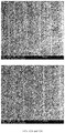
- FIGS. 6A and 6B show SEM images of internally patterned 3.5 mm PCLF tubes.
- 6 A 100 ⁇ magnification
- 6 B 1000 ⁇ magnification.
- FIG. 7 shows the fluorescent confocal microscopy image of actin aligned in cells on a longitudinally sliced internally patterned 3.5 mm PCLF tube. Actin is stained in this image.
- FIGS. 8A and 8B show SEM images of an internally patterned 1.5 mm PCLF tube.
- the gap in the pattern in (A) was created by a structural reinforcement band on the shadow mask.
- FIG. 9 shows a schematic diagram of a typical shadow mask for patterning the inside of small tubes, and SEM pictures of sections of a typical mask.
- FIGS. 10-16 are scanning electron micrographs (SEMs) of the inside of a 1.5 mm ID PCLF tube.
- the tube, with the shadow mask inserted, is exposed to vapor of zirconium tetra(tert-butoxide), Zr(O-tBu) 4 , for either 10 min or 5 min, as noted, then warmed, followed by treatment with a solution of 1,4-diphosphonobutane.
- SEMs scanning electron micrographs
- FIGS. 10A and 10B show a SEM of the inside of a 1.5 mm ID PCLF tube, 10-min Zr tetra(tert-butoxide) exposure, scale bar is 3 mm (50 ⁇ magnification). There is some waviness in the pattern because of the fragility of the mask.
- FIG. 10B shows a 200 ⁇ magnification in the region of the “structural bar” of the mask; scale bar is 500 ⁇ m.
- FIGS. 11A and 11B show a SEM of the inside of a 1.5 mm ID PCLF tube, 5-min Zr tetra(tert-butoxide) exposure, 100 ⁇ magnification.
- FIG. 11B shows a 200 ⁇ magnification in the region of the structural bar.
- FIGS. 12A and 12B show a SEM of the inside of a 1.5 mm ID PCLF tube, 5-min Zr tetra(tert-butoxide) exposure, 1000 ⁇ magnification.
- FIG. 12B shows a 1500 ⁇ magnification.
- FIG. 13 shows a SEM of the inside of a 1.5 mm ID PCLF tube, 5-min Zr tetra(tert-butoxide) exposure, 1500 ⁇ magnification showing Zr concentrated in alternating stripes, as expected based on the masking pattern. Apparently a small amount of Zr has crept under the mask.
- FIGS. 14A and 14B show a SEM of the inside of a 1.5 mm ID PCLF tube, 5-min Zr tetra(tert-butoxide) exposure, 1500 ⁇ magnification.
- FIG. 14B shows an XPS analysis of the same tube, indicating that Zr is concentrated in the desired stripe motif.
- FIG. 15 shows a SEM of the inside of a 1.5 mm ID PCLF tube, 5-min Zr tetra(tert-butoxide) exposure, 75 ⁇ magnification in segments 1 through 3 of 5 of the tube.
- FIG. 16 shows a SEM of the inside of the same 1.5 mm ID PCLF tube, 5-min Zr tetra(tert-butoxide) exposure, 75 ⁇ magnification in segments 4 and 5 of 5 of the tube.
- FIGS. 17A and 17B show cross-sectional SEM images of a physically patterned 1.5 mm ID PCLF tube demonstrating that applying pressure to the shadow mask while heating creates a physical pattern in the polymer.
- 17 A and 17 B show the same tube cross section at different magnifications.
- Channel depth is about 4-5 ⁇ m.
- FIGS. 18A and 18B shows a comparison of the alignment of surface-embossed PCLF polymer tubes incubated with cells attached by fibronectin, versus polymers having aligned ECM using Zr(O-tBu) 4 /SAMP (Self-Assembled Monolayer of Phosphonate) attachment.
- FIGS. 19A, 19B, 19C, 19D, 19E, 19F and 19G show the results of embossing OPF with a shadow mask: Un-embossed OPF ( 19 A), and top view ( 19 B) and cross section ( 19 C) of an embossed OPF sample observed under environmental scanning electron microscopy (ESEM) in low vacuum mode.
- a 3D confocal microscopy of a piece of dehydrated OPF at room temperature and pressure before and after embossing are shown in 19 D and 19 E, respectively.
- a 3D confocal image and its profile at the drawn line are shown in 19 F and 19 G, respectively.
- Embossing changes the physical appearance of the OPF, forming ridges ranging from 10 ⁇ m to 20 ⁇ m in height.
- FIGS. 20A and 20B shows the results of surface treatment of OPF with shadow masking: An SEM image of embossed OPF with Zr/SAMP treatment ( 20 A) and its cross section ( 20 B); areas covered by the mask are shown as darker indentations, whereas the areas not covered by the mask are bright, high ridges.
- FIGS. 21A, 21B, 21C, 21D, 21E and 21F show the results of embossing TECOFLEXTM EG-80A: Embossing with physical modifications under ESEM for top view ( 21 A) and cross section ( 21 B), and 3D confocal microscopy ( 21 C). Embossing without physical modifications under ESEM for top view ( 21 D) and cross section ( 21 E), and 3D confocal microscopy ( 21 F).
- the elasticity of TECOFLEXTM limited physical modifications on its surface, but the shadow mask was still adhered in both cases. Only the edges of the pattern underwent physical modifications.
- FIGS. 22A and 22B show a profile of embossed TECOFLEXTM EG-80A from 3D confocal microscopy: ( 22 A) embossed TECOFLEXTM with large ridges, up to 6 ⁇ m in height; ( 22 B) embossed TECOFLEXTM with small ridges, as low as 2 ⁇ m.
- FIGS. 23A and 23B show the results of surface treatment of TECOFLEXTM with shadow masking: An SEM image of embossed TECOFLEXTM with Zr/SAMP treatment ( 23 A) and its cross section ( 23 B); areas covered by the mask are shown as darker stripes, whereas the areas not covered by the mask are bright.
- Photolithography is a common chemical treatment carried out to pattern thin films or bulk substrates.
- a suitable photoresist deposited onto the substrate and a photomask
- the layer of photoresist is treated with UV light to transfer a geometric pattern from the mask to the material below the photoresist.
- the unexposed regions will remain covered by photoresist and the regions not covered by the photomask will be washed away by subsequent chemical treatments, leaving behind patterns on the treated substrate.
- certain materials are incompatible with this microfabrication process.
- PCLF polycaprolactone fumarate
- Shadow masking is a process whereby a physical mask is used to shadow surface areas of materials that will not be treated. Thus, for shadow masking to successfully pattern the surface of a material, an intimate contact between the mask and the material must be established. Shadow masking has been successfully carried out by the present inventors with soft polymers that have fairly low glass transition temperatures (T g ). The relatively low T g can be easily reached by gentle heating over a hotplate, at which point the materials become soft and sticky, and can be readily adhered onto a shadow mask. It has now been discovered that the shadow masks can be pressed onto the material, e.g., between two clean glass slides, and then removed after surface treatments, leaving behind patterned surface treatments on areas that were not physically covered by the shadow mask. These shadow masks can be cleaned and reused. In this way such masks are used as a mechanical contrivance, like a die, to physically emboss the surface of suitable substrate polymers.
- Suitable substrate polymers have a relatively low glass transition temperature (T g ), between about 50 and about 100° C., preferably about 55 to about 90° C.
- Such polymers can be selected from the group consisting of polyamides, polyurethanes, polyureas, polyesters, polyketones, polyimides, polysulfides, polysulfoxides, polysulfones, polythiophenes, polypyridines, polypyrroles, polyethers, silicone (polysiloxanes), polysaccharides, fluoro-polymers, epoxies, aramides, amides, imides, polypeptides, polyolefins, polyethylene, polystyrene, poly-propylene, liquid crystal polymers, thermoplastics, polyvinyls, poly(vinyl alcohol), polyacrylics, polyacrylates, poly(acrylic acid), polycarbonates, polytetrafluoroethylene (PTFE), polyethylene terephthalate (PET
- the polymer is selected from the group consisting of polycaprolactone fumarate (PCLF), oligo-(polyethylene glycol) fumarate (OPF), and aliphatic polyether-based thermoplastic polyurethanes (such as TECOFLEXTM polymers, e.g. TECOFLEXTM EG-80A).
- PCLF polycaprolactone fumarate
- OPF oligo-(polyethylene glycol) fumarate
- aliphatic polyether-based thermoplastic polyurethanes such as TECOFLEXTM polymers, e.g. TECOFLEXTM EG-80A.
- TECOFLEXTM polymers e.g. TECOFLEXTM EG-80A
- the substrate polymer is PCLF.
- OPF oligo-(polyethylene glycol) fumarate
- aliphatic polyether-based thermoplastic polyurethanes such as TECOFLEXTM polymers, e.g. TECOFLEXTM
- aliphatic polyether-based thermoplastic polyurethane class include the commercial offerings of Lubrizol under the tradename TECOFLEXTM. These polymers are the reaction products of dodecahydro-methylene diphenyl diisocyanate (H 12 -MDI, also known as 4,4′-dicyclohexylmethane diisocyanate) and ⁇ , ⁇ -diols (such as polytetramethylene glycol and 1,4-butanediol), as represented by the following reaction scheme:
- H 12 -MDI also known as 4,4′-dicyclohexylmethane diisocyanate
- ⁇ , ⁇ -diols such as polytetramethylene glycol and 1,4-butanediol
- Suitable commercial TECOFLEXTM polymer grades include EG-80A, EG-85A, EG-93A, EG-100A, EG-60D, EG-65D, EG-68D, and EG-72D.
- Suitable shadow mask polymers include, without limitation, polyimides, poly(methylmethacrylate) (PMMA) and parylenes.
- Parylenes include, without limitation, parylene N, parylene C and parylene D.
- the parylene is parylene C.
- the shadow masks are preferably made of KAPTON®, a flexible polyimide film that remains stable throughout a wide range of temperatures ( ⁇ 269° C. to 400° C.).
- the patterns used were stripes with a pitch of 50 ⁇ m and 15 ⁇ m wide lines surrounded by about 35 ⁇ m of KAPTON® or other polymer. The resulting patterns that were developed from these masks were approximately 30 ⁇ m alternating stripes.
- Shadow masks are preferably formed by ablating appropriate polymer coupons.
- the ablation is laser ablation; therefore, the masking polymers should be sensitive to laser ablation.
- Masks should be thick enough to produce a useful embossed pattern, but not so thin that the mask will fracture.
- the shadow masks should have an appropriate balance of rigidity and flexibility. If the shadow mask is too thick, it will not conform to the substrate polymer, especially for a 3D substrate.
- shadow masks for embossing have a thickness of about 25 ⁇ m. In some embodiments the embossing shadow masks are about 20 to about 30 ⁇ m thick.
- the masks can be 20, or 21, or 22, or 23, or 24, or 25, or 26, or 27, or 28, or 29, or 30 ⁇ m thick.
- a device for nerve regeneration including a scaffold polymer supporting a native, highly aligned ECM template to stimulate and guide neurite outgrowth across an injury site.
- the complexity of a native ECM characterized by highly aligned fibrils renders it virtually impossible to synthesize de novo in the lab.
- the present invention recapitulates the inherent complexity of ECM by inducing cells to construct it.
- the present invention demonstrates that development of a chemically patterned polymer substrate provides a surface that facilitates the construction of a highly aligned native-like ECM by fibroblast cells plated on the surface.
- neural analog PC12 cells were plated on a decellularized ECM that was assembled by fibroblast cells on a 1,4-butanediphosphonic acid-functionalized surface.
- Unpatterned substrates induce the formation of ECM marked by fibronectin fibrils in random orientation (unpatterned ECM); this unpatterned ECM directs neurite outgrowth by PC12 cells, but randomly, not directionally.
- a patterned ECM constructed by fibroblasts plated on 10 ⁇ 10 1,4-butanediphosphonic acid-patterned PET (poly(ethylene terephthalate)) or PCLF (polycaprolactone fumarate), however, directs neurite outgrowth in register with the aligned ECM and underlying chemical pattern.
- That neuron surrogate cells plated on a decellularized, highly aligned ECM platform extend neurites in the direction of the ECM fibrils indicates that a cell-assembled matrix provides a starting point for constructing a nerve regeneration scaffold.
- a device employing PET as a scaffold polymer would not be useful for addressing nerve regeneration because of a mechanical properties mismatch:
- the elastic modulus of PET (2 GPa) is 6 orders of magnitude stiffer than the glial cells that support neurons and 5 orders of magnitude stiffer than the fibroblasts that assemble the ECM.
- a scaffold polymer with the correct mechanical properties should be employed.
- PCLF polycaprolactone fumarate
- PNS peripheral nervous system
- PCLF has been formulated to match the mechanical properties of a peripheral nerve.
- Conduits fabricated from PCLF have been shown to be biocompatible when used to repair a sciatic nerve defect in a rat model. While PCLF conduits are biocompatible and mechanically suited for the PNS, such conduits alone do not stimulate and guide individual axons that must bridge the gap between the two ends of a severed nerve; further, their closed structure may inhibit waste removal and the diffusion of nutrients and oxygen to the regenerating nerve.
- Nerve conduits such as PCLF tubes, used in vivo are of different sizes with respect to their internal diameter (ID), depending on the size of the neurons, which is also related to species. Thus, for rat model testing, smaller ID tubes are required, in the range of about 1 to about 1.5 mm ID. However, for human use the conduits should be about 5 to about 8 mm ID.
- ID internal diameter
- the presently disclosed patterning method allows the construction of nerve conduits having a broad range of internal diameters, from about 1 mm to about 8 mm, and beyond.
- the nerve regeneration scaffold or construct is in the form of a tube or tube-like structure, or a folded device.
- the tube or tube-like structure can be a rolled species, a rolled-up system, a preformed tube, or a species of similar geometry.
- a patterned interface is essential to the assembly of the highly aligned, native-like ECM by fibroblast cells plated on PET; a striped chemical pattern of 1,4-butanediphosphonic acid templates the adhesion, spreading and proliferating the cells in alignment and facilitating their construction as a similarly aligned matrix.
- a physically patterned interface in the polymer itself may be sufficient to induce the assembly of a highly aligned ECM, vide infra.
- the method for chemically functionalizing PET with a patterned ZrO 2 /SAMP (Self-Assembled Monolayer of Phosphonate) interface involves photolithographic patterning of PET substrates followed by vapor deposition of a volatile organometallic complex to link the cell adhesive phosphonate to the polymer in a striped pattern.
- This process proved to be incompatible with PCLF because of the adhesion between the photolithographic reagents and PCLF. Due to the incompatibility of the photolithographic process and the polymer, in order to achieve patterning of PCLF with 1,4-butanediphosphonic acid a new process had to be developed based on physical masking for chemical evaporation rather than photolithographic masking.
- PCLF's unique properties make it ideally suited for peripheral nerve repair, its surface chemistry renders it especially problematic for photolithography.
- Substrates patterned by photolithography are generally pre-baked (e.g., at 95° C.); however, upon heating PCLF to only 40° C., the polymer undergoes a phase transition from amorphous to crystalline, thereby altering the polymer's physical properties. Attempted photolithography was, therefore, performed with careful attention to avoid elevated temperatures, and also omitted the pre-bake step.
- a photoresist solution was spin-cast on PCLF, and the photoresist solvent was evaporated to cure the layer either by exposure to air flow at room temperature or with a post-bake at 30° C.; PCLF substrates coated with photoresist were then patterned by exposure to UV light under a 30 ⁇ 30 photomask and developed with the standard alkaline developer. After UV exposure and development the photoresist could not be removed to expose the native PCLF; the characteristic structure of PCLF was not revealed when photolithography was performed after curing the photoresist by either evaporation of solvent or after a post-bake at 30° C.
- Shadow masking is a common technique used for chemical vapor deposition in the fabrication of microelectronics. Shadow masking employs a physical stencil mask through which a volatile chemical is evaporated to form a pattern on a substrate. Vapor deposition through a shadow mask generally requires special equipment to maintain intimate contact between the mask and the substrate so that there is no bleed of chemical vapor around the edges of the mask. Previous attempts to pattern other polymer and silicon substrates through shadow masking evidenced poor adhesion between the mask and the substrate without such specialized mask alignment equipment.
- the poor adhesion between the mask and the substrates allowed for exposure of the entire substrate surface to vapor; thus, the surface became completely coated with zirconium oxide, rather than confining the surface functionalization to the desired pattern.
- FIG. 1 shows the inventive scheme in which a polymer such as PCLF is mildly heated to enhance the “stickiness” of the surface (step 1).
- a shadow mask template fabricated by laser ablation of a flexible polyimide (such as KAPTON®) coupon is placed above the PCLF substrate (step 2).
- the PCLF-mask ensemble is exposed to Zr(O-tBu) 4 at 1 ⁇ 10 ⁇ 3 torr, then mildly heated to form a mixed zirconium oxide/alkoxide interface in patterns on the surface of PCLF after removal of the mask (step 3); alkoxide ligands are replaced by phosphonate groups after immersion in a solution of 1,4-butanediphosphonic acid (step 4) yielding PCLF functionalized with the patterned ZrO 2 /phosphonate (ZrO 2 /SAMP) interface.
- a physical shadow mask was fabricated from KAPTON®: Stripes with targeted dimensions of about 30 ⁇ m ⁇ 30 ⁇ m were ablated from a 120 ⁇ m thick coupon of KAPTON®.
- the KAPTON® mask was placed on a PCLF coupon (1 cm ⁇ 1 cm) after heating the polymer mildly (from room temperature up to about 80° C., preferably up to about 50° C., but not higher than the glass transition temperature of the polymer) to increase “stickiness;” the process of heating PCLF did not change the surface morphology of PCLF once it cooled and returned to the amorphous phase.
- the mask-PCLF ensemble was then placed in a vapor deposition chamber and volatile zirconium tetra(tert-butoxide) was evaporated through the chamber at 1 ⁇ 10′ torr for 30 seconds; Zr(O-tBu) 4 coordinates to the oxygen functionalities of the PCLF only where the PCLF surface is exposed through the mask.
- Zr(O-tBu) 4 coordinates to the oxygen functionalities of the PCLF only where the PCLF surface is exposed through the mask.
- a cross-linked zirconium oxide/alkoxide layer was formed on the PCLF substrate; subsequent immersion in a solution of 1,4-butanediphosphonic acid exchanged the alkoxide ligands for phosphonates yielding the ZrO 2 /SAMP interface in patterns on the surface.
- the concentration range of the 1,4-butanediphosphonic acid solution is from about 1 micromolar to about 1 millimolar in an appropriate solvent, with ethanol or methanol being preferred. After rinsing with isopropanol, patterns could be easily observed using an optical microscope.
- XP spectra of both clean PCLF and 1,4-butanediphosphonic acid-patterned PCLF were taken to confirm successful functionalization with the ZrO 2 /SAMP interface; phosphorous could not be detected by EDS because the Zr (L ⁇ ) peak (2.42 eV) overlapped with the P (K ⁇ ) peak (2.12 eV), and was more intense. While the XP spectrum of clean PCLF showed binding energy (B.E.) peaks that correspond to C(1s) and O(1s) electrons, the XP spectrum of 1,4-butanediphosphonic acid-patterned PCLF indicated the introduction of peaks that corresponded to Zr(3d) and P(2p) electrons.
- FIG. 2 shows NIH 3T3 fibroblasts spread on shadow mask-patterned PCLF stained for actin after 24 hours (A) and 3 days (B).
- FFT Fast Fourier transform
- FIG. 2 shows NIH 3T3 fibroblasts spread on shadow mask-patterned PCLF stained for actin after 24 hours (A) and 3 days (B).
- FFT Fast Fourier transform
- Lines through ovals on FFT images represent length and width measurements used to measure aspect ratio, which is indicated at the bottom right.
- Actin stained with rhodamine phalloidin; scale bar 100 ⁇ m. Alignment was quantified on each surface by FFT analysis by measuring the aspect ratio of the FFT output image. The aspect ratio was derived by dividing the vertical dimension of the oval by the horizontal dimension of the oval that is produced by the FFT.
- the FFT produces an image in which the width of the oval (the horizontal line) is rotated 90° with regard to the (vertical) pattern direction; thus perfect alignment with a pattern that is vertical on the page would generate an FFT that is a perfect horizontal line. Therefore, the longer the horizontal line and the shorter the vertical one (giving the smallest numerical ratio), the better the alignment of the cells with the pattern; perfect alignment would have a ratio of zero.
- NIH 3T3 cells were plated on 1,4-butanediphosphonic acid-patterned PCLF to evaluate whether the patterned interface could facilitate cell alignment as well as PET, PEEK, and nylon. Cells adhered and spread preferentially with the pattern after 24 hours ( FIG. 2A ) and proliferated to confluence in alignment with the pattern ( FIG. 2B ).
- FFT output aspect ratio was derived by dividing the width of the oval by the length of the oval: the smaller the ratio, the better the alignment.
- the patterned 1,4-butanediphosphonic acid-interface could be fabricated on PCLF via shadow mask templated cell alignment having analytical parameters the same as the 1,4-butanediphosphonic acid-patterned interface constructed on PET, PEEK, or nylon using photolithography.
- FIG. 3 shows fibronectin assembled by 3T3 cells after 3 days on 1,4-butanediphosphonic acid-patterned PCLF (A) and PET (B) substrates; FFT outputs of the actin images from PCLF and PET surfaces are displayed in (C) and (D), respectively. Lines through ovals on FFT images represent length and width measurements used to measure the aspect ratio, which is indicated at the bottom right.
- Alignment was quantified on each surface by fast Fourier transform (FFT) analysis by measuring the aspect ratio of the FFT output image. The aspect ratio was derived by dividing the vertical dimension of the oval by the horizontal dimension of the oval that is produced by the FFT.
- FFT fast Fourier transform
- FFT produces an image in which the width of the oval (the horizontal line) is rotated 90° with regard to the (vertical) pattern direction; thus perfect alignment with a pattern that is vertical on the page would generate an FFT that is a perfect horizontal line. Therefore, the longer the horizontal line and the shorter the vertical one (giving the smallest numerical ratio), the better the alignment of the cells with the pattern; perfect alignment would have a ratio of zero.
- ECM assembly on PCLF patterned with 1,4-butanediphosphonic acid using the shadow mask technique was compared to ECM assembly on photolithographically 1,4-butanediphos-phonic acid-patterned PET.
- 3T3 cells plated at 50,000 cells/well assembled a fibronectin matrix that was aligned with the pattern on both PCLF ( FIG. 3A ) and PET ( FIG. 3B ).
- Quantification of fibronectin images by FFT yielded ovals with virtually equivalent aspect ratios: 0.68 for PCLF ( FIG. 3C ) and 0.67 ( FIG. 3D ). It was clear that ZrO 2 /SAMP patterns facilitated assembly of aligned fibronectin whether they are constructed on the hard model polymer PET or the softer, more flexible and PNS-compatible material PCLF.
- Shadow mask patterning proved to be particularly useful for patterning PCLF; it also provided a powerful tool to pattern other materials whose surface chemical or materials properties are incompatible with the reagents or processes of photolithography due to chemical incompatibility with the photolithography reagents (photoresist, solvents, and other chemicals required for the process), or are incompatible due to the physical nature of the surface (e.g., curved versus planar).
- Another unique benefit of the physical shadow mask is that it adheres to the PCLF surface; the flexibility of a KAPTON® mask allows it to conform to a substrate surface even when the polymer surface is curved.
- the glass tube-PCLF-mask construct was placed in a chamber and exposed to vapor of Zr(O-tBu) 4 , mildly heated, and then placed in solution of 1,4-butanediphosphonic acid to form the 1,4-butanediphosphonic acid-interface in stripes on the PCLF surface as described above.
- FIG. 4A shows the 1,4-butanediphosphonic acid-patterned interface on a curved PCLF substrate; the 3D rendition of the confocal image ( FIG. 4B ) and corresponding height profile ( FIG. 4C ) illustrate that the pattern has been constructed on the concave face of a curved surface.
- Patterning can also be done on a scaffold or construct which already has the form of a tube or tube-like structure, or a folded device.
- the tube or tube-like structure can be a rolled species, a rolled-up system, a preformed tube, or a species of similar geometry.
- the patterning is on the inside, or interior surface of the tube or tube-like scaffold.
- the shadow mask patterning technology can be applied to other substrate materials that are currently believed to be incompatible as substrates for photolithography for surface reactivity and/or surface geometry reasons.
- these incompatible materials include natural polymer scaffolds, such as collagen or silk, or conducting polymers, such as PEDOT:PSS (Poly(EthyleneDiOxyThiophene): Poly(Styrene Sulfonate)); OPF, and PCLF; or hydrogels of poly(ethylene oxide), poly(ethylene glycol), cross-linked poly(acrylic acid), poly(acrylamides), poly(acrylates), sucrose, carbohydrate glass, alginate, chitosan, or chondroitin which are destroyed by the reagents of photolithography.
- PEDOT:PSS Poly(EthyleneDiOxyThiophene): Poly(Styrene Sulfonate)
- OPF Poly(Styrene Sulfonate)
- PCLF PCLF
- the polymer comprises polyamides, polyurethanes, polyureas, polyesters, polyketones, polyimides, polysulfides, polysulfoxides, polysulfones, polythiophenes, polypyridines, polypyrroles, polyethers, silicone (polysiloxanes), polysaccharides, fluoro-polymers, epoxies, aramides, amides, imides, polypeptides, polyethylene, polystyrene, poly-propylene, liquid crystal polymers, thermoplastics, polyvinyls, polyacrylics, polyacrylates, polycarbonates, polytetrafluoroethylene (PTFE), polyethylene terephthalate (PET), poly(vinyl-pyrrolidone), poly(-hydroxyethyl methacrylate), poly(N-vinylpyrrolidone), poly(methyl methacrylate), poly(vinyl alcohol), poly(acrylic acid), polyacrylamide, polyethylene
- Hydrogels are a particularly attractive material for the inventive shadow mask patterning technology in the context of nerve repair.
- Oligo-(polyethylene glycol) fumarate (OPF) a hydrogel currently under preclinical investigation as a scaffold for spinal cord by the Mayo Clinic, is one such hydrogel.
- Others include poly(ethylene oxide), poly(ethylene glycol), cross-linked poly(acrylic acid), poly(acrylamides), poly(acrylates), sucrose, carbohydrate glass, alginate, chitosan, and chondroitin.
- Hydrogels are too mechanically flimsy for spin coating (photolithography process) and are too sensitive to liquid reagents to employ as a substrate for construction of patterned interfaces using photolithographic methods, but are amenable to surface patterning via shadow masking.
- a 1,4-butanediphosphonic acid-patterned interface templates the alignment of cell-assembled ECM, such that a device consisting of the scaffold polymer OPF supporting highly-aligned, cell-assembled ECM could be tested for regeneration of a spinal cord injury in vivo.
- PCLF-ECM templates for PNS repair and OPF-ECM scaffolds for spinal cord injury repair require that these scaffolds can first be tested and optimized in vitro for biological function relative to the nervous system.
- a co-culture of fibroblasts and Schwann cells may support the construction of a more neurotrophic ECM; additionally, growth factors may need to be added to the ECM to better stimulate neurite outgrowth or neuron survival.
- bona fide neurons such as dorsal root ganglion cells can be tested for their response to the patterned ECM.
- neurons and neural cells include neurons from CNS or PNS, neural support cells such as Schwann cells and radial glial cells, neural stem cells such as cells that form neurospheres, and neural tumor cells such as glioblastoma and neuroblastoma cells.
- a 3D device must also be constructed to match the dimensions of a peripheral nerve or spinal cord; this device can be constructed from stacks of 2D layers of templated ECM, or it can consist of a 2D sheet of patterned ECM rolled into a 3D tube.
- a nerve regeneration device based on a polymer-ECM bridge can be constructed using the disclosed technology. Specifically, a simple chemical pattern can be constructed on both hard and soft polymer surfaces via substrate-compatible techniques, and that pattern facilitates the assembly of aligned ECM by cells on these patterned surfaces.
- a superior method to control cell alignment on polymers with targeted application to nerve regeneration, muscle growth/regrowth, and other in vitro and in vivo applications, is now available via patterning of fragile polymer surfaces and/or non-planar surfaces.
- photolithography was employed to make the patterns through a multi-step process involving spin-coating a photoresist on the polymer, followed by exposure to UV radiation through a mask, followed by development in alkali.
- a shadow mask (a perforated mask) is placed onto and adhered to the polymer, and the metal alkoxide precursor of the pattern is evaporated onto the polymer; no photolithography is involved, and the shadow mask patterns provide equally good benefits for cell alignment.
- the metal alkoxide is selected from Zr, Ti, Group 5 or Group 6 metals, where Group 5 metals include V, Nb and Ta, and Group 6 metals include Cr, Mo and W.
- the metal alkoxide is a zirconium alkoxide.
- the present procedure enables the rapid preparation of templates for nerve regeneration, about 10 times faster than the previously described photolithography methods, and also is amenable to very soft polymers, including hydrogels, and to polymer substrates having curved surfaces.
- One aspect of the invention is directed to a polymeric substrate that is incompatible with photolithography conditions, at least a portion of a surface of which comprises a material suitable for cell attachment, in a pattern which is raised above the surface of the substrate.
- the raised pattern comprises the polymer of the polymeric substrate.
- the raised pattern comprises at least one cell-binding or cell-adhesive material.
- the polymeric substrate can be incompatible with photolithography conditions due to one or more incompatibilities selected from the group consisting of temperature incompatibility, solvent incompatibility, reagent incompatibility, and surface geometry incompatibility.
- the surface geometry incompatibility comprises surface curvature.
- the curvature comprises a curved surface selected from the group consisting of inward-curving concave surfaces and outward-curving convex surfaces.
- the polymeric substrate is in the form of a tube or a tube-like structure and the raised-patterned surface is on the interior of the tube or tube-like structure.
- the tube or tube-like structure can be a rolled species, a rolled-up system, a preformed tube, or a species of similar geometry.
- Another aspect of the invention is directed to a method of patterning a surface of a polymeric substrate which is incompatible with photolithography conditions, comprising the steps of a) providing a shadow mask, b) applying the shadow mask to a surface of the polymeric substrate to form a masked substrate, c) applying pressure to the shadow mask surface of the masked substrate, optionally with heating sufficient to form a phase transition in the polymer of the polymeric substrate, d) optionally, cooling the masked substrate, and e) removing the mask to reveal a physically patterned polymeric surface.
- the applied pressure must be sufficient to emboss the polymer surface so that the negative pattern of the shadow mask is formed in the polymer surface. If required, this can be accomplished with simultaneous heating of the polymeric substrate to a softening temperature which depends on the polymer, so that the polymeric substrate is amenable to pressurized embossing.
- the polymeric substrate can be incompatible with photolithography conditions due to one or more incompatibilities selected from the group consisting of temperature incompatibility, solvent incompatibility, reagent incompatibility, and surface geometry incompatibility.
- the surface geometry incompatibility comprises surface curvature.
- the patterning is on the inside surface of a tube, a tube-like substrate, or a folded substrate.
- the tube or tube-like substrate can comprise a rolled species, a rolled-up system, a preformed tube, or a species of similar geometry.
- the polymeric substrate is a preformed tube having patterning on the inside surface.
- any cell-adhesive material for the physically patterned, embossed polymeric substrates, any cell-adhesive material, or a material that becomes cell-adhesive in plasma, can be used to adhere cells to the physical pattern and form the ECM.
- cell-adhesive materials include collagen, fibronectin, and laminin.
- Example 10 vide infra, discloses internally physically patterned PCLF tubes with an ECM formed using fibronectin.
- Yet another aspect of the invention is directed to a method of preparing a shadow mask for patterning the inside surface of a polymeric tube which is incompatible with photo-lithography conditions, comprising the steps of a) providing a coupon of polymer having a thickness of about 10 ⁇ m to about 120 ⁇ m, and having appropriate dimensions to completely cover the inside surface of a polymeric tube, and b) ablating the coupon to remove selected segments of the polymer, providing a desired pattern; wherein the coupon polymer is adherent to the interior surface of the polymeric tube such that the peel strength therebetween is less than the tensile strength of either of the coupon polymer or the polymeric tube.
- the ablation comprises laser ablation.
- the polymeric tube can be incompatible with photolithography conditions due to one or more incompatibilities selected from the group consisting of temperature incompatibility, solvent incompatibility, reagent incompatibility, and surface geometry incompatibility.
- incompatibilities selected from the group consisting of temperature incompatibility, solvent incompatibility, reagent incompatibility, and surface geometry incompatibility.
- the surface geometry incompatibility comprises surface curvature.
- Still another aspect of the invention is directed to a construct which supports cell attachment and alignment, comprising a) a substrate which is incompatible with photo-lithography conditions; b) a patterned coating of a metal alkoxide, oxide or mixed oxide-alkoxide disposed thereon; and c) a phosphonic acid covalently attached to b), which phosphonic acid contains functionality adapted for cell binding.
- the metal alkoxide is selected from Zr, Ti, Group 5 or Group 6 metals, where Group 5 metals include V, Nb, and Ta, and Group 6 metals include Cr, Mo and W.
- the metal alkoxide is a zirconium alkoxide.
- One embodiment of the construct further comprises cells attached thereto.
- construct further comprises an aligned extracellular matrix (ECM).
- ECM aligned extracellular matrix
- the substrate can be incompatible with photolithography conditions due to one or more incompatibilities selected from the group consisting of temperature incompatibility, solvent incompatibility, reagent incompatibility, and surface geometry incompatibility.
- the surface geometry incompatibility comprises surface curvature.
- Another aspect of the invention is directed to a construct which supports cell attachment and alignment, comprising: a) a substrate which is incompatible with photolithography conditions; and b) a patterned coating of a cell-adhesive compound disposed thereon.
- the cell-adhesive compound comprises fibronectin.
- the cell-adhesive compound is fibronectin.
- the construct further comprises cells attached thereto.
- the construct further comprises an aligned extracellular matrix (ECM).
- ECM aligned extracellular matrix
- the phosphonic acid comprises one or more functional groups selected from the group consisting of polyol moieties, sugar alcohol moieties, hydroxyl functional groups, amino functional groups, carboxylic acid functional groups, carboxylate ester functional groups, phosphonic acid functional groups, phosphonate functional groups, ether functional groups, alkyne functional groups, azide functional groups and thiol functional groups.
- the phosphonic acid is 1,4-butanediphosphonic acid.
- the substrate comprises a polymer selected from the group consisting of polyamides, polyurethanes, polyureas, polyesters, polyketones, polyimides, polysulfides, polysulfoxides, polysulfones, polythiophenes, polypyridines, polypyrroles, polyethers, silicone (polysiloxanes), polysaccharides, fluoro-polymers, epoxies, aramides, amides, imides, polypeptides, polyolefins, polyethylene, polystyrene, poly-propylene, liquid crystal polymers, thermoplastics, polyvinyls, poly(vinyl alcohol), polyacrylics, polyacrylates, poly(acrylic acid), polycarbonates, polytetrafluoroethylene (PTFE), polyethylene terephthalate (PET), poly(vinyl-pyrrolidone), poly(-hydroxyethyl methacrylate), poly(N-vinyl
- the substrate polymer comprises PCLF, OPF, or an aliphatic polyether-based thermoplastic polyurethane.
- the substrate polymer is PCLF.
- the substrate polymer is OPF.
- the substrate polymer is an aliphatic polyether-based thermoplastic polyurethane, such as TECOFLEXTM EG-80A.
- the patterned coating is on the inside surface of a tube, a tube-like substrate, or a folded substrate.
- the tube or tube-like substrate can comprise a rolled species, a rolled-up system, a preformed tube, or a species of similar geometry.
- Another aspect of the invention is directed to a method of preparing a construct which supports cell attachment and alignment, the method comprising a) providing a substrate which is incompatible with photolithography conditions; b) preparing a shadow mask template consisting of a material which is adherent to the substrate such that the peel strength is less than the tensile strength of the shadow mask and substrate material; and c) adhering the shadow mask template to the substrate to form a substrate-mask ensemble.
- One embodiment of the method further comprises d) exposing the substrate-mask ensemble to a metal alkoxide to form a treated substrate-mask ensemble; e) warming the treated ensemble and removing the mask from the treated substrate-mask ensemble to form a metal oxide/alkoxide patterned surface; and f) covalently attaching to the patterned surface a phosphonic acid containing functionality adapted for cell binding, to form the construct.
- the metal alkoxide is selected from Zr, Ti, Group 5 or Group 6 metals, where Group 5 metals include V, Nb and Ta, and Group 6 metals include Cr, Mo and W.
- the metal alkoxide is a zirconium alkoxide.
- Another embodiment of the method further comprises d) formation of a raised patterned surface by application of pressure, and optionally heat, to the substrate-mask ensemble; e) removing the mask from the substrate-mask ensemble to expose the raised patterned surface; and f) exposing the raised patterned surface to a cell-adhesive biomaterial to form the construct.
- the unmasked patterned substrate can be exposed directly to a cell-adhesive biomaterial such as fibronectin.
- Other embodiments further comprise the step of attaching cells to the construct.
- Still other embodiments further comprise the step of incubating the construct to form an aligned extracellular matrix (ECM).
- ECM aligned extracellular matrix
- the substrate can be incompatible with photolithography conditions due to one or more incompatibilities selected from the group consisting of temperature incompatibility, solvent incompatibility, reagent incompatibility, and surface geometry incompatibility.
- the surface geometry incompatibility comprises surface curvature.
- the substrate comprises a tube, a tube-like, or a folded structure and wherein the inside surface of the substrate is patterned.
- the tube or tube-like structure can comprise a rolled species, a rolled-up system, a preformed tube, or a structure of similar geometry.
- the phosphonic acid comprises one or more functional groups selected from the group consisting of polyol moieties, sugar alcohol moieties, hydroxyl functional groups, amino functional groups, carboxylic acid functional groups, carboxylate ester functional groups, phosphonic acid functional groups, phosphonate functional groups, ether functional groups, alkyne functional groups, azide functional groups and thiol functional groups.
- the phosphonic acid is 1,4-butanediphosphonic acid.
- the substrate comprises a polymer selected from the group consisting of polyamides, polyurethanes, polyureas, polyesters, polyketones, polyimides, polysulfides, polysulfoxides, polysulfones, polythiophenes, polypyridines, polypyrroles, polyethers, silicone (polysiloxanes), polysaccharides, fluoro-polymers, epoxies, aramides, amides, imides, polypeptides, polyolefins, polyethylene, polystyrene, poly-propylene, liquid crystal polymers, thermoplastics, polyvinyls, poly(vinyl alcohol), polyacrylics, polyacrylates, poly(acrylic acid), polycarbonates, polytetrafluoroethylene (PTFE), polyethylene terephthalate (PET), poly(vinyl-pyrrolidone), poly(-hydroxyethyl methacrylate), poly(N-vinyl
- the substrate polymer comprises PCLF, OPF or an aliphatic polyether-based thermoplastic polyurethane.
- the substrate polymer is PCLF.
- the substrate polymer is OPF.
- the substrate polymer is an aliphatic polyether-based thermoplastic polyurethane, such as TECOFLEXTM EG-80A.
- One aspect of the invention is directed to a scaffold or construct which supports cell attachment and alignment, comprising a) a substrate which is incompatible with photo-lithography conditions; b) a patterned coating of a metal alkoxide, oxide or mixed oxide-alkoxide thereon; and c) a phosphonic acid covalently attached to b), which phosphonic acid contains functionality adapted for cell binding.
- the metal alkoxide is selected from Zr, Ti, Group 5 or Group 6 metals, where Group 5 metals include V, Nb and Ta, and Group 6 metals include Cr, Mo and W.
- the metal alkoxide is a zirconium alkoxide.
- the scaffold or construct further comprises cells attached thereto. Preferably, these cells are attached via a phosphonic acid residue or linker, which phosphonic acid has the formula (I):
- the R group can be selected from the group consisting of alkyl, heteroalkyl, alkenyl, heteroalkenyl, alkynyl, heteroalkynyl, aryl, arylalkyl, heteroaryl, and heteroarylalkyl, where heteroalkyl, heteroalkenyl, heteroalkynyl, heteroaryl and heteroarylalkyl contain one or more heteroatoms selected from the group consisting of O, N and S.
- the R group can be optionally substituted (vide infra).
- the scaffold or construct further comprises an aligned extracellular matrix (ECM).
- ECM aligned extracellular matrix
- the substrate is incompatible with photolithography conditions by virtue of one or more incompatibilities selected from the group consisting of temperature incompatibility, solvent incompatibility, reagent incompatibility, and surface geometry incompatibility.
- temperature incompatibility means heating to a temperature above the melting point, or decomposition point, or softening temperature of the polymer or hydrogel so that degradation or some other irreversible change occurs such that the polymer or hydrogel fails to provide a useful scaffold; solvent incompatibility means that erosion, degradation or some other change occurs such that the polymer or hydrogel fails to provide a useful scaffold; reagent incompatibility means that adsorption, absorption, degradation, contamination or some other change occurs such that the polymer or hydrogel fails to provide a useful scaffold.
- Surface geometry incompatibility means that the surface is formed such that the shadow mask fails to adhere evenly to the surface and therefore fails to provide distinct patterning when the substrate-mask ensemble is exposed to Zr(O-tBu) 4 , or other metalating agent. This is characteristic of a curved surface or the inside surface of a tube, where a photoresist cannot be applied uniformly.
- the surface geometry incompatibility comprises surface curvature, either convex or concave.
- the phosphonic acid comprises one or more functional groups selected from the group consisting of polyol moieties, sugar alcohol moieties, hydroxyl functional groups, amino functional groups, carboxylic acid functional groups, carboxylate ester functional groups, phosphonic acid functional groups, phosphonate functional groups, ether functional groups, alkyne functional groups, azide functional groups and thiol functional groups; preferably as substituents on the organic moiety R.
- at least one functional group is attached to the omega-position of R.
- R can also be further substituted with one or more alkyl, alkoxy, halo or hydroxy groups.
- the phosphonic acid is 1,4-butanediphosphonic acid, where the functional group of the phosphonic acid discussed above is a phosphonic acid functional group.
- the substrate comprises a polymer selected from the group consisting of polyamides, polyurethanes, polyureas, polyesters, polyketones, polyimides, polysulfides, polysulfoxides, polysulfones, polythiophenes, polypyridines, polypyrroles, polyethers, silicone (polysiloxanes), polysaccharides, fluoro-polymers, epoxies, aramides, amides, imides, polypeptides, polyolefins, polyethylene, polystyrene, poly-propylene, liquid crystal polymers, thermoplastics, polyvinyl s, poly(vinyl alcohol), polyacrylics, polyacrylates, poly(acrylic acid), polycarbonates, polytetrafluoroethylene (PTFE), polyethylene terephthalate (PET), poly(vinyl-pyrrolidone), poly(-hydroxyethyl methacrylate), poly(N-vinylpyrroli
- the polymer is selected from the group consisting of polycaprolactone fumarate (PCLF), oligo-(polyethylene glycol) fumarate (OPF), an aliphatic polyether-based thermoplastic polyurethane (such as TECOFLEXTM EG-80A), collagen, silk and PEDOT:PSS.
- PCLF polycaprolactone fumarate
- OPF oligo-(polyethylene glycol) fumarate
- an aliphatic polyether-based thermoplastic polyurethane such as TECOFLEXTM EG-80A
- collagen silk and PEDOT:PSS.
- PEDOT:PSS is a common conducting organic polymer, consisting of two components, Poly(EthyleneDiOxy-Thiophene), a cationic material, and Poly(Styrene Sulfonate), the counter anion.
- the substrate polymer is PCLF.
- Another preferred embodiment of the substrate polymer is OPF.
- a further preferred embodiment of the substrate polymer is
- Another aspect of the invention is directed to a method of preparing a construct which supports cell attachment and alignment, the method comprising a) providing a substrate which is incompatible with photolithography conditions; b) preparing a shadow mask template consisting of a material which is adherent to the substrate such that the peel strength is less than the tensile strength of the shadow mask and substrate material; c) adhering the shadow mask template to the substrate to form a substrate-mask ensemble; d) exposing the substrate-mask ensemble to a metal alkoxide to form a treated substrate-mask ensemble; e) removing the mask from the treated substrate-mask ensemble to form a metal oxide/alkoxide patterned surface; and f) covalently attaching to the patterned surface a phosphonic acid containing functionality adapted for cell binding, to form the scaffold or construct.
- the metal alkoxide is selected from Zr, Ti, Group 5 or Group 6 metals.
- the metal alkoxide is a zirconium alkoxide
- the shadow mask template can be made to contact the substrate by factors including the gravitational force of the mask over the substrate, and/or the physical adhesion between the mask and the substrate such that the peel strength is less than the tensile strength of the shadow mask and substrate materials.
- the method further comprises g) attaching cells to the construct.
- the method further comprises h) incubating the construct to form an aligned extracellular matrix (ECM).
- ECM aligned extracellular matrix
- the substrate is incompatible with photolithography conditions by virtue of one or more incompatibilities selected from the group consisting of temperature incompatibility, solvent incompatibility, reagent incompatibility, and surface geometry incompatibility.
- the surface geometry incompatibility comprises surface curvature.
- Another embodiment of the surface geometry incompatibility comprises the inside surface of a tubular substrate.
- the phosphonic acid comprises one or more functional groups selected from the group consisting of polyol moieties, sugar alcohol moieties, hydroxyl functional groups, amino functional groups, carboxylic acid functional groups, carboxylate ester functional groups, phosphonic acid functional groups, phosphonate functional groups, ether functional groups, alkyne functional groups, azide functional groups and thiol functional groups.
- the phosphonic acid is 1,4-butanediphosphonic acid.
- the substrate comprises a polymer selected from the group consisting of polycaprolactone fumarate (PCLF), oligo-(polyethylene glycol) fumarate (OPF), an aliphatic polyether-based thermoplastic polyurethane (such as TECOFLEXTM EG-80A), collagen, silk, PEDOT:PSS, poly(ethylene oxide), poly(ethylene glycol), cross-linked poly(acrylic acid), poly(acrylamides), poly(acrylates), sucrose, carbohydrate glass, alginate, chitosan, and chondroitin.
- the substrate polymer is PCLF.
- the substrate polymer is OPF.
- the substrate polymer is an aliphatic polyether-based thermoplastic polyurethane, preferably TECOFLEXTM EG-80A.
- fragment indicates chemical or physical incompatibility with the reagents, and/or solvents, and/or processes involved in photolithography. This can include incompatibility with the photoresist itself or other reagents and/or solvents involved in photolithography. This can also include incompatibility with the conditions of the process, such as heating to a temperature above the melting point, or decomposition point, or softening temperature of the polymer or hydrogel.
- incompatible means causing negative interactions or effects so that the scaffold-forming process fails to produce a scaffold, or the resulting scaffold fails to be useful for its intended purpose or fails to lead to the intended outcome.
- Poly(ethylene glycol) (PEG), poly(ethylene oxide) (PEO), or polyoxyethylene (POE) refers to an oligomer or polymer of ethylene oxide.
- the three names are chemically synonymous, but historically PEG has tended to refer to oligomers and polymers with a molecular mass below 20,000 g/mol, PEO to polymers with a molecular mass above 20,000 g/mol, and POE to a polymer of any molecular mass.
- PCLF substrates were acquired from Dr. Huan Wang (Mayo Clinic); isopropanol, formaldehyde, 4′,6-diamidino-2-phenylindole (DAPI) (Sigma-Aldrich); zirconium tetra(tert-butoxide), Zr(O-tBu) 4 (Strem Chemicals, Inc.); 1,4-butanediphosphonic acid (Acros Organics); phosphate buffered saline (PBS), rhodamine phalloidin (Invitrogen); trypsin, versene (LifeTech); Dulbecco's modified eagle medium (DMEM), bovine calf serum (BCS) (Hyclone); nonylhenoxypolyethoxylethanol (NP-40) (EMD Chemicals); and 200 proof ethanol (Pharmco-Aaper) were used as received.
- DAPI isopropanol, formaldehyde, 4′,6-d
- NIH 3T3 fibroblasts were maintained in DMEM supplemented with 10% BCS (v/v) and passaged 1:10 by volume twice each week. Trypsin was added to versene before using it to lift cells off tissue culture plates.
- KAPTON® polyimide film (DuPont) is poly(4,4′-oxydiphenylene-pyromellitimide).
- XPS X-ray photoelectron spectroscopy
- Polymer substrates were characterized with a FEI Quanta 200 Environmental-SEM equipped with an Oxford INCA Synergy 450 energy-dispersive X-ray microanalysis system with an X-Max 80 large area analytical silicon drift detector (SDD) at an acceleration voltage of 5 keV. SEM and EDS were performed in low-vacuum mode (0.53 torr) to avoid melting of the polymer by the electron beam.
- PCLF coupons were rinsed with isopropanol and dried under a stream of nitrogen. Coupons were placed on a glass slide on a hot plate at 45° C. to heat the coupons slowly. The progress of PCLF phase transition from amorphous to crystalline occurred over about 30 seconds, and could be observed visually as the substrate changed from white and opaque to clear and translucent. Once the phase transition was complete, the glass slide was removed from the hot plate and the KAPTON® shadow mask was placed on the PCLF substrate. The two sides of the KAPTON® were distinct, so careful attention was paid to ensure that the side with stripes of the target pattern dimension contacted the PCLF coupon. Once the mask was placed on the PCLF substrate, it was gently pushed against the polymer with tweezers to achieve optimal adhesion. Mask adhesion occurred similarly for the curved PCLF, with the only exception being that PCLF was heated inside a glass tube such that the polymer was pushed to conform to the glass tube.
- PCLF-shadow mask and glass tube-PCLF-shadow mask ensembles were placed inside a deposition chamber equipped with two valves; one was connected to vacuum and the other to a bulb containing Zr(O-tBu) 4 .
- the chamber was evacuated to 1 ⁇ 10 ⁇ 3 torr for 10 min. Samples were exposed to vapor of Zr(O-tBu) 4 for 30 sec with the chamber opened to vacuum. The bulb and chamber were sealed; the chamber was wrapped with heat tape and was warmed to 35° C.
- the chamber was then cooled to room temperature and subsequently evacuated to 1 ⁇ 10 ⁇ 3 torr for 5 min. After evacuation, the chamber was closed to vacuum and back-filled with zero-grade nitrogen. After closing the valves of both sides of the chamber, the chamber was removed from the vacuum line.
- the substrates were quickly removed from the chamber and placed in individual vials containing a solution of 1,4-butanediphosphonic acid in ethanol (0.25 mg/mL) for 16 hr to yield polymer films functionalized with 1,4-butanediphosphonic acid. It should be noted that formation of the phosphonate monolayer occurs within minutes of immersion in phosphonic acid solution, so the full 16 hour soak may not be necessary. Substrates were then rinsed with isopropanol, dried under nitrogen, and then assessed by optical microscopy.
- NIH 3T3 fibroblasts were plated at 50,000 cells per well on 1,4-butanediphosphonic acid-patterned polymer substrates. Cells were fixed at time points of 24 hours and 3 days using 3.7% formaldehyde in PBS for 15 min, permeabilized with 0.5% NP-40 (v/v) in PBS for 15 min at room temperature; cell actin was stained with rhodamine-phalloidin (1:40) and cell nuclei were stained with DAPI (1:1000). Antibodies were diluted by volume in PBS containing 2% BSA. Cells were plated on all surfaces in duplicate.
- FFT Fast Fourier transform
- NIH 3T3 cells were plated at 50,000 cells/well, as described above, on 1,4-butanediphosphonic acid-patterned PET and PCLF substrates. After 3 days, cells were fixed using 3.7% formaldehyde in PBS for 15 min and stained with R457 (1:100) for 30 minutes. After rinsing with PBS, cells were incubated in AlexaFluor 488 (1:400) goat-anti-rabbit secondary IgG. Antibodies were diluted by volume in PBS containing 2% BSA. Fibronectin was visualized by fluorescent microscopy; FFT analysis was performed as described above.
- the new method of adhesion is as follows: shadow masks were manually rolled and inserted into tubes before PCLF is made sticky, in order to ensure proper shadow mask placement. Nichrome wire heated by passage of electrical current was applied in order to mildly heat the mask and PCLF surface from the inside so as to allow the PCLF to become sticky and the mask to adhere without causing the external surface of the tube to undergo a phase change and deform. Once proper adhesion was attained, zirconium tetra(tert-butoxide) was deposited onto the surface and alkoxide ligands were exchanged for phosphonate as described above. Placing the surface in the phosphonate-ethanol solution also weakens adhesion of the shadow mask to the PCLF and allows for removal of the shadow mask without damage to the inside of the PCLF tube or to the newly formed chemical pattern.
- PCLF tubes of internal diameter 3.5 mm and 1.5 mm were prepared and cleaned by rinsing in isopropanol and drying under nitrogen. Shadow masks of target dimensions 30 ⁇ m ⁇ 30 ⁇ m with a width optimized for the 1.5 mm ID tubes were created through laser ablation of KAPTON®. Shadow masks were rolled manually and inserted into 3.5 mm tubes, or rolled around an 18 gauge needle and inserted into 1.5 mm tubes. Masks were adhered to PCLF by inserting a Nichrome wire into the tube, which was heated by passage of electrical current, and applying pressure to the shadow mask until the PCLF phase transition could be identified visually (white to colorless) at which point it was sticky enough to enable adhesion of the KAPTON® shadow mask. An image of a shadow mask inside a 3.5 mm internal diameter PCLF tube is shown in FIG. 5 .
- NIH 3T3 cells were suspended in DMEM growth media with serum (10% BCS) at a dilution of 250,000 cells/mL.
- PBS was used to rinse patterned PCLF tubes three times. Tubes were securely placed into the opening of a 200 ⁇ L micropipette tip. The ensemble was then placed into a 1.5 mL Eppendorf centrifuge tube in order to allow for rotation of the PCLF tube, ensuring cell adhesion on all sides. Cell solution was injected directly inside the PCLF tube until the Eppendorf tube was full. The Eppendorf tube was then laid horizontally on a tube rotator and allowed to turn for 1.5 hours to allow for cell adhesion. The PCLF tube was removed and placed in 1.5 mL of serum-containing media for 2 days. The cells were then fixed, permeabilized, and stained for actin using the same reagents described for flat PCLF by pipetting reagents into the tube. Fluorescence microscopy was used to image longitudinally sliced tubes.
- XPS analysis confirmed ZrO 2 -phosphonate (ZrO 2 -SAMP) binding.
- the unpatterned surface showed peaks for O(1s) at 557.5 eV and C(1s) at 284.5 eV. Patterning the surface yielded peaks for Zr(3d) at 183.5 eV, Zr(3p) at 347.5 eV and 333.5 eV, and P(2p) at 133.5 eV.
- the unpatterned surface also showed a peak for F(1s) at 688.5 eV that was not present on the patterned surface. This peak likely represents a product formed during PCLF creation that was eliminated by the surface modification method.
- SEM images of patterned tubes showed uniform stripes over the entire surface ( FIG. 6 ).
- 3T3 Fibroblast cells were plated inside this tube by injection directly into the tube and continuous rotation and were shown to align with the pattern.
- a fluorescent confocal microscopy image of cells aligned along the ZrO 2 -SAMP stripes on the inside of the patterned PCLF tube is shown in FIG. 7 . Actin is stained in this image.
- PCLF tubes of 3.5 mm ID were successfully patterned using the present method of shadow masking.
- the inside of a narrow tube can be patterned via shadow masking and chemical vapor deposition (CVD).
- CVD chemical vapor deposition
- cells were shown to attach to all sides of the inside of this tube and thus ECM construction will not be constrained to one side of the tube by gravity.
- Cell alignment along the ZrO 2 -SAMP stripes showed that this polymer-chemical substrate can direct the growth of fibroblast cells and can also direct the growth of the ECM that these cells construct. It is believed that this is the first example of chemically patterning the inside of a pre-formed tube.
- the presently disclosed chemical pattern aligns cells not only on flat surfaces but in tubes as well; indicating that aligned ECM can be generated inside a tube.
- the shadow mask could be removed (without any chemical treatment) to reveal a physically patterned or textured PCLF tube where the interior polymer surface retains the pattern of the shadow mask as a negative image.
- This physical patterning of the polymer surface is also referred to herein as “embossing”.
- Suitable neurons and neural cells for such nerve conduits include neurons from CNS or PNS, neural support cells such as Schwann cells and radial glial cells, neural stem cells such as cells that form neurospheres, and neural tumor cells such as glioblastoma and neuroblastoma cells.
- a flat KAPTON® mask could be manipulated to pattern curved or tube-shaped PCLF surfaces.
- Shadow masks for use in small tubes were designed to maintain a mechanical integrity over long length scales with patterning on small length scales.
- the mask was machined by laser or otherwise to create 30 micrometer by 50,000 micrometer (5 cm) openings in a 5 mm by 100 mm strip.
- the mask is made of sections or segments where the 30 micrometer openings are extended to 5,000 micrometers long, after which the pattern is disrupted by a cross support (structural bar) of the shadow mask polymer in order to maintain the mechanical integrity of the shadow mask.
- the shadow mask is made of sufficiently thin polymeric material to allow for easily deforming the mask to cover conformal to the inside of a cylindrical sample (i.e., a tube to be patterned).
- the thickness of the mask polymer ranges from about 10 ⁇ m to about 120 ⁇ m, preferably from about 10 to about 75 ⁇ m, more preferably from about 20 to about 50 ⁇ m.
- Thicker masks do not readily conform to the inside diameter of small (e.g. 1 mm ID) tubes, and the thinner masks tend to be fragile in handling, so the choice of thickness depends on the physical properties of the mask polymer as well as on the inside diameter of the tube substrate.
- a typical shadow mask is shown in FIG. 9 .
- the laser used for machining the mask was a pulsed diode pumped solid state (neodymium-doped yttrium orthovanadate) laser, with a frequency tripled output operating wavelength of 355 nanometers.
- the laser energy was roughly 30 microJoules per pulse, and operated up to 25 kilohertz.
- the laser was focused to a spot size of approximately 10 micrometers in diameter.
- High precision linear translation stages were used to position the sample and trigger the laser to fire at every 0.5 micrometer of motion, to produce a 10 micrometer wide cut having the desired pattern in the mask.
- PCLF polymer tubes internally embossed with a physical pattern as above were submerged and incubated with soluble rat fibronectin (10 ⁇ g/ml) in phosphate buffered saline (PBS) for 1 hour at 37° C. The tubes were then washed 3 times with PBS and 40,000 cells/cm 2 were seeded onto the polymer. The cell-seeded polymer tubes were cultured for 1 day or 7 days. Phase contrast images of the polymer and patterned lines are shown in FIG. 18A .
- FFT Fast Fourier Transform
- Extracellular matrix (ECM) alignment for the surface-embossed PCLF tubes treated with fibronectin was compared to alignment on a coupon of PCLF patterned with ZrO 2 -SAMP and a coupon of poly(ethylene terephalate) (PET) patterned with ZrO 2 -SAMP.
- Full width half max (FWHM) of FFT graphs were used to compare alignments using the ZrO 2 -SAMP surface chemistry and shadow mask tube patterning-fibronectin approaches as shown in FIG. 18B .
- OPF is a soft and flexible polymer that has a T g of about 55° C. Since the primary form of OPF is a hydrogel, the material presents itself as a polymeric matrix that easily swells up to about 800% of its original weight in water. When a dry piece of OPF was heated to its T g , the polymer softens can be shaped with some slight pressure. Exploiting this malleable characteristic of OPF, a piece of OPF ( FIG. 19A ) was patterned by embossing a 30 ⁇ m-lined shadow mask onto its surface, as shown in FIG. 19B . Since OPF was designed as a biomedical hydrogel that can be used for drug delivery, the hydrogel is essentially porous.
- the piece of polymer was compressed, giving not only surface embossment but also a change in its cross section, as shown in FIG. 19C .
- This method of patterning the piece of polymer proved to maintain the surface's chemical integrity ( FIG. 19 ).
- An infrared (IR) analysis showed that the chemical composition on the OPF surface before and after patterning remained the same. Aside from physically changing the topography of the OPF surface to form physical ridges, shadow masking can also be used as a physical blockage when an interface is deposited onto the polymer surface, leaving behind surface treatments only on exposed areas.
- TECOFLEXTM is a flexible, medical-grade aliphatic polyether-based thermoplastic polyurethane.
- the T g of TECOFLEXTM EG-80A, the softest grade of clear TECOFLEXTM (supplied by Lubrizol) was found to be about 80° C. At this temperature, the material is sticky and can easily be adhered to a KAPTON® mask, similar to that of dehydrated OPF. However, unlike dehydrated OPF, this material is elastic and slightly stretchable, even at room temperature, so its elasticity enables it to bounce back to its original shape and provides a lower degree of physical modification (embossing). However, FIGS. 21 and 22 show that this polymer also provides a useful substrate for embossing. As for OPF, the process of shadow masking preserves the chemical integrity of the TECOFLEXTM surface. An IR analysis before and after embossing did not show much spectral differences, with all the distinctive peaks still in place.
- the shadow mask was concluded to have intimate adherence to the surface because subsequent Zr/SAMP surface treatment showed distinct differences on the surface. Qualitatively, the surface appeared cloudy with the interface and upon analysis under ESEM and EDS, the Zr/SAMP interface was found only on areas not covered by the shadow mask, leaving unexposed areas with little Zr and P detected. Some cracking on Zr/SAMP stripes were observed because the polymer swelled when it was being put into a phosphonic acid solution for SAMP treatment. However, upon drying, the polymer shrank to its original size with no major pattern modifications.
- both an EDS element mapping and a line scan proved to be more telling in terms of where the elements were restricted.
- both the P and Zr atoms were largely confined to the bright stripes on the electron images captured by the SEM, showing that the shadow mask successfully blocks the deposition of these elements on the sample surface.
- shadow masking has now been demonstrated to be a technique that acts as a template to physically pattern the surfaces of soft and flexible polymers, such as PCLF, dehydrated OPF and TECOFLEXTM EG-80A.
- shadow masking under appropriate temperature and pressure conditions modifies the surface topography of these materials. Porous and compressible dehydrated OPF conformed to the shape of the masks, resulting in ridged patterns.
- the elastic TECOFLEXTM was more resistant to physical change. Regardless, both materials managed to adhere intimately with the KAPTON® shadow masks when they were heated to their T g . Upon their adherence, during surface treatments, shadow masks acted as physical barriers to block the growth of a chemical interface on these surfaces.
- a patterned Zr/SAMP interface was successfully deposited on both dehydrated OPF and TECOFLEXTM via shadow masking.
- a flexible KAPTON® shadow mask can pattern soft, flexible materials such as the aforementioned polymers, which cannot be achieved by traditional surface patterning via photolithography.
Abstract
Description

Suitable commercial TECOFLEX™ polymer grades include EG-80A, EG-85A, EG-93A, EG-100A, EG-60D, EG-65D, EG-68D, and EG-72D.

where attachment to the metal alkoxide is via the phosphonate head unit, and attachment of the cells is via the organic tail moiety R of the phosphonic acid residue. The R group can be selected from the group consisting of alkyl, heteroalkyl, alkenyl, heteroalkenyl, alkynyl, heteroalkynyl, aryl, arylalkyl, heteroaryl, and heteroarylalkyl, where heteroalkyl, heteroalkenyl, heteroalkynyl, heteroaryl and heteroarylalkyl contain one or more heteroatoms selected from the group consisting of O, N and S. The R group can be optionally substituted (vide infra). In one embodiment the scaffold or construct further comprises an aligned extracellular matrix (ECM). In one embodiment the substrate is incompatible with photolithography conditions by virtue of one or more incompatibilities selected from the group consisting of temperature incompatibility, solvent incompatibility, reagent incompatibility, and surface geometry incompatibility.
Claims (37)

Priority Applications (1)
| Application Number | Priority Date | Filing Date | Title |
|---|---|---|---|
| US15/649,033 US10646896B2 (en) | 2015-01-21 | 2017-07-13 | Patterning of fragile or non-planar surfaces for cell alignment |
Applications Claiming Priority (4)
| Application Number | Priority Date | Filing Date | Title |
|---|---|---|---|
| US201562105804P | 2015-01-21 | 2015-01-21 | |
| US201562152222P | 2015-04-24 | 2015-04-24 | |
| PCT/US2016/012791 WO2016118349A1 (en) | 2015-01-21 | 2016-01-11 | Patterning of fragile or non-planar surfaces for cell alignment |
| US15/649,033 US10646896B2 (en) | 2015-01-21 | 2017-07-13 | Patterning of fragile or non-planar surfaces for cell alignment |
Related Parent Applications (1)
| Application Number | Title | Priority Date | Filing Date |
|---|---|---|---|
| PCT/US2016/012791 Continuation-In-Part WO2016118349A1 (en) | 2015-01-21 | 2016-01-11 | Patterning of fragile or non-planar surfaces for cell alignment |
Publications (2)
| Publication Number | Publication Date |
|---|---|
| US20170312780A1 US20170312780A1 (en) | 2017-11-02 |
| US10646896B2 true US10646896B2 (en) | 2020-05-12 |
Family
ID=56417589
Family Applications (1)
| Application Number | Title | Priority Date | Filing Date |
|---|---|---|---|
| US15/649,033 Active 2036-05-05 US10646896B2 (en) | 2015-01-21 | 2017-07-13 | Patterning of fragile or non-planar surfaces for cell alignment |
Country Status (2)
| Country | Link |
|---|---|
| US (1) | US10646896B2 (en) |
| WO (1) | WO2016118349A1 (en) |
Families Citing this family (4)
| Publication number | Priority date | Publication date | Assignee | Title |
|---|---|---|---|---|
| EP3668447A4 (en) | 2017-08-17 | 2021-05-12 | The Trustees of Princeton University | Ultrathin interfacial layer on a hydrogel to direct its surface properties and cell adhesion |
| KR102206911B1 (en) * | 2018-11-30 | 2021-01-25 | 한국생산기술연구원 | Method for treating metal surface and metal surface modified using the same |
| GB201905040D0 (en) * | 2019-04-09 | 2019-05-22 | Cambridge Entpr Ltd | Tissue equivalent scaffold structure, and methods of procution thereof |
| CN111793899B (en) * | 2020-04-30 | 2021-06-18 | 杭州医学院 | Bionic nanofiber material and preparation method and application thereof |
Citations (12)
| Publication number | Priority date | Publication date | Assignee | Title |
|---|---|---|---|---|
| US20020050220A1 (en) | 2000-08-14 | 2002-05-02 | Olivier Schueller | Deformable stamp for patterning three-dimensional surfaces |
| US20020095219A1 (en) | 2000-10-20 | 2002-07-18 | Gabriele Nelles | Method of forming a cell pattern on a surface, cellular networks and tissues based theron |
| US6645644B1 (en) | 1996-10-17 | 2003-11-11 | The Trustees Of Princeton University | Enhanced bonding of phosphoric and phosphoric acids to oxidized substrates |
| US20040096476A1 (en) | 2002-07-17 | 2004-05-20 | Uhrich Kathryn E. | Therapeutic devices for patterned cell growth |
| US20060085063A1 (en) * | 2004-10-15 | 2006-04-20 | Shastri V P | Nano- and micro-scale engineering of polymeric scaffolds for vascular tissue engineering |
| US20060194008A1 (en) * | 1999-09-22 | 2006-08-31 | Princeton University | Devices with multiple surface functionality |
| US20080131709A1 (en) | 2006-09-28 | 2008-06-05 | Aculon Inc. | Composite structure with organophosphonate adherent layer and method of preparing |
| US7396594B2 (en) | 2002-06-24 | 2008-07-08 | The Trustees Of Princeton University | Carrier applied coating layers |
| US20080299169A1 (en) | 2005-08-12 | 2008-12-04 | Diane Hoffman-Kim | Topographical Templating of Polymeric Materials Using Cellular Morphology |
| US20090104474A1 (en) | 2007-10-17 | 2009-04-23 | Princeton University | Functionalized substrates and methods of making same |
| US20140330392A1 (en) | 2011-12-07 | 2014-11-06 | The Trustees Of Princeton University | Scaffolds for tissues and uses thereof |
| US9056154B2 (en) | 2006-02-21 | 2015-06-16 | The Trustees Of Princeton University | High-yield activation of polymer surfaces for covalent attachment of molecules |
-
2016
- 2016-01-11 WO PCT/US2016/012791 patent/WO2016118349A1/en active Application Filing
-
2017
- 2017-07-13 US US15/649,033 patent/US10646896B2/en active Active
Patent Citations (13)
| Publication number | Priority date | Publication date | Assignee | Title |
|---|---|---|---|---|
| US7879456B2 (en) | 1996-10-17 | 2011-02-01 | Jeffrey Schwartz | Carrier applied coating layers |
| US6645644B1 (en) | 1996-10-17 | 2003-11-11 | The Trustees Of Princeton University | Enhanced bonding of phosphoric and phosphoric acids to oxidized substrates |
| US20060194008A1 (en) * | 1999-09-22 | 2006-08-31 | Princeton University | Devices with multiple surface functionality |
| US20020050220A1 (en) | 2000-08-14 | 2002-05-02 | Olivier Schueller | Deformable stamp for patterning three-dimensional surfaces |
| US20020095219A1 (en) | 2000-10-20 | 2002-07-18 | Gabriele Nelles | Method of forming a cell pattern on a surface, cellular networks and tissues based theron |
| US7396594B2 (en) | 2002-06-24 | 2008-07-08 | The Trustees Of Princeton University | Carrier applied coating layers |
| US20040096476A1 (en) | 2002-07-17 | 2004-05-20 | Uhrich Kathryn E. | Therapeutic devices for patterned cell growth |
| US20060085063A1 (en) * | 2004-10-15 | 2006-04-20 | Shastri V P | Nano- and micro-scale engineering of polymeric scaffolds for vascular tissue engineering |
| US20080299169A1 (en) | 2005-08-12 | 2008-12-04 | Diane Hoffman-Kim | Topographical Templating of Polymeric Materials Using Cellular Morphology |
| US9056154B2 (en) | 2006-02-21 | 2015-06-16 | The Trustees Of Princeton University | High-yield activation of polymer surfaces for covalent attachment of molecules |
| US20080131709A1 (en) | 2006-09-28 | 2008-06-05 | Aculon Inc. | Composite structure with organophosphonate adherent layer and method of preparing |
| US20090104474A1 (en) | 2007-10-17 | 2009-04-23 | Princeton University | Functionalized substrates and methods of making same |
| US20140330392A1 (en) | 2011-12-07 | 2014-11-06 | The Trustees Of Princeton University | Scaffolds for tissues and uses thereof |
Non-Patent Citations (6)
| Title |
|---|
| Chang et al., "Modulation of neural network activity by patterning," Biosensors & Bioelectronics (2001); 16:527-533. |
| Danahy et al., "Self-assembled Monolayrs of a,w-Diphosphonic Acids on Ti Enable Complete or Spatially Controlled Surface Derivatization," Langmuir (2004); 20:5333-5337. |
| Pae et al., "Attachment and growth behaviour of human gingival fibroblasts on titanium and zirconia ceramic surcases," Biomed. Mater. (2009)4:1-7. |
| Saneinejad et al., "Patterned glass surfaces direct cell adhesion and process outgrowth of primary neurons of the central nervous system," Biomed. Mater. Res. (1998); 42(10):13-19. |
| Teixeira et al., "Responses of human keratocytes to micro- and nanostructured substrates" J. Biomed. Mater. Res. (2004); 71A:369-376. |
| Viviani, Barbara, "Preparation and Coculture of Neurons and Glial Cells," Current Protocols in Cell Biology (2006); 32:2.7.1-2.7.21. |
Also Published As
| Publication number | Publication date |
|---|---|
| US20170312780A1 (en) | 2017-11-02 |
| WO2016118349A1 (en) | 2016-07-28 |
Similar Documents
| Publication | Publication Date | Title |
|---|---|---|
| US10646896B2 (en) | Patterning of fragile or non-planar surfaces for cell alignment | |
| Chang et al. | Effect of surface potential on NIH3T3 cell adhesion and proliferation | |
| Yang et al. | Molecular imaging of a micropatterned biological ligand on an activated polymer surface | |
| Yue et al. | Bio-functionalisation of polydimethylsiloxane with hyaluronic acid and hyaluronic acid–Collagen conjugate for neural interfacing | |
| US10563160B2 (en) | Scaffolds for tissues and uses thereof | |
| Yu et al. | A novel and simple microcontact printing technique for tacky, soft substrates and/or complex surfaces in soft tissue engineering | |
| Goessl et al. | Control of shape and size of vascular smooth muscle cells in vitro by plasma lithography | |
| Lin et al. | Micropatterning proteins and cells on polylactic acid and poly (lactide-co-glycolide) | |
| Aufan et al. | Facile synthesis of conductive polypyrrole wrinkle topographies on polydimethylsiloxane via a swelling–deswelling process and their potential uses in tissue engineering | |
| Xu et al. | Easy, scalable, robust, micropatterned silk fibroin cell substrates | |
| Koppes et al. | Complex, multi-scale small intestinal topography replicated in cellular growth substrates fabricated via chemical vapor deposition of Parylene C | |
| Palamà et al. | Micropatterned polyelectrolyte nanofilms promote alignment and myogenic differentiation of C2C12 cells in standard growth media | |
| Alvarez-Paino et al. | Polymer microparticles with defined surface chemistry and topography mediate the formation of stem cell aggregates and cardiomyocyte function | |
| Pidhatika et al. | Surface-attached dual-functional hydrogel for controlled cell adhesion based on poly (N, N-dimethylacrylamide) | |
| Kim et al. | Eggshell membrane as a bioactive agent in polymeric nanotopographic scaffolds for enhanced bone regeneration | |
| Kim et al. | Plasma-assisted multiscale topographic scaffolds for soft and hard tissue regeneration | |
| US20070269883A1 (en) | Micropatterning surfaces | |
| Satpathy et al. | Bio‐mimicked g uided tissue regeneration/guided bone regeneration membranes with hierarchical structured surfaces replicated from teak leaf exhibits enhanced bioactivity | |
| US11364105B2 (en) | Scaffolds for neural tissue and uses thereof | |
| Sarkar et al. | Fabrication of a layered microstructured polycaprolactone construct for 3-D tissue engineering | |
| Erkoc‐Biradli et al. | Bioinspired hydrogel surfaces to augment corneal endothelial cell monolayer formation | |
| EP2618857A1 (en) | Medical device | |
| US20030104614A1 (en) | Micropatterning surfaces of polymeric substrates | |
| Steuber et al. | Guided assembly, nanostructuring and functionalization with brushes of microscale polymer cubes for tailored 3-D cell microenvironments | |
| Majani et al. | Preparation of Caco-2 cell sheets using plasma polymerised acrylic acid as a weak boundary layer |
Legal Events
| Date | Code | Title | Description |
|---|---|---|---|
| AS | Assignment |
Owner name: NATIONAL SCIENCE FOUNDATION, VIRGINIA Free format text: CONFIRMATORY LICENSE;ASSIGNOR:PRINCETON UNIVERSITY;REEL/FRAME:044819/0136 Effective date: 20171204 |
|
| STPP | Information on status: patent application and granting procedure in general |
Free format text: RESPONSE TO NON-FINAL OFFICE ACTION ENTERED AND FORWARDED TO EXAMINER |
|
| STPP | Information on status: patent application and granting procedure in general |
Free format text: NON FINAL ACTION MAILED |
|
| STPP | Information on status: patent application and granting procedure in general |
Free format text: RESPONSE TO NON-FINAL OFFICE ACTION ENTERED AND FORWARDED TO EXAMINER |
|
| STPP | Information on status: patent application and granting procedure in general |
Free format text: NOTICE OF ALLOWANCE MAILED -- APPLICATION RECEIVED IN OFFICE OF PUBLICATIONS |
|
| STPP | Information on status: patent application and granting procedure in general |
Free format text: AWAITING TC RESP., ISSUE FEE NOT PAID |
|
| STCF | Information on status: patent grant |
Free format text: PATENTED CASE |
|
| AS | Assignment |
Owner name: THE TRUSTEES OF PRINCETON UNIVERSITY, NEW JERSEY Free format text: ASSIGNMENT OF ASSIGNORS INTEREST;ASSIGNORS:SCHWARTZ, JEFFREY;SPECHLER, JOSHUA;FARDEL, ROMAIN;AND OTHERS;SIGNING DATES FROM 20200114 TO 20220404;REEL/FRAME:059499/0050 Owner name: THE TRUSTEES OF PRINCETON UNIVERSITY, NEW JERSEY Free format text: ASSIGNMENT OF ASSIGNORS INTEREST;ASSIGNORS:BANDINI, STEPHEN;ADLER, LILY;PARIKH, ALOMI;AND OTHERS;SIGNING DATES FROM 20210804 TO 20220315;REEL/FRAME:059504/0148 |
|
| CC | Certificate of correction | ||
| MAFP | Maintenance fee payment |
Free format text: PAYMENT OF MAINTENANCE FEE, 4TH YR, SMALL ENTITY (ORIGINAL EVENT CODE: M2551); ENTITY STATUS OF PATENT OWNER: SMALL ENTITY Year of fee payment: 4 |