US1064423A - Socket for lamps, &c. - Google Patents
Socket for lamps, &c. Download PDFInfo
- Publication number
- US1064423A US1064423A US68575512A US1912685755A US1064423A US 1064423 A US1064423 A US 1064423A US 68575512 A US68575512 A US 68575512A US 1912685755 A US1912685755 A US 1912685755A US 1064423 A US1064423 A US 1064423A
- Authority
- US
- United States
- Prior art keywords
- lining
- csp
- ere
- cop
- clips
- Prior art date
- Legal status (The legal status is an assumption and is not a legal conclusion. Google has not performed a legal analysis and makes no representation as to the accuracy of the status listed.)
- Expired - Lifetime
Links
Images
Classifications
-
- H—ELECTRICITY
- H10—SEMICONDUCTOR DEVICES; ELECTRIC SOLID-STATE DEVICES NOT OTHERWISE PROVIDED FOR
- H10P—GENERIC PROCESSES OR APPARATUS FOR THE MANUFACTURE OR TREATMENT OF DEVICES COVERED BY CLASS H10
- H10P70/00—Cleaning of wafers, substrates or parts of devices
- H10P70/10—Cleaning before device manufacture, i.e. Begin-Of-Line process
- H10P70/18—Cleaning before device manufacture, i.e. Begin-Of-Line process by combined dry cleaning and wet cleaning
Definitions
- ll-'iy invention relates perticulerly to improveniente in Ineens for fastening the inisolating iinine in the csp end ineens for securing or locliing the oep end body of the slieil together.
- Sockets of this clierscter ere used perticulerly for inclosing incondescent electric lomp switch besos end else niiet ere i commonly termed rendent switches.
- @ne object is to provide s sim le und inexpensive Ineens o securing the lining of tlie cop in piece.
- these cs. 1ininggs ere mede of very denible motorie such es thin peper which 1t is 'difiicult to hold securely in place und the thin s er is likely to be torn in handling.
- a tiiicr end rigid lining is preferable es it sli'ords e more pericct means of insulation, for instance, porcelsin or heevy liber.
- the special object of my invention is to eiord Ineens of securing such e heevy lining in piece preferably so that it can be rcedily inserted or removed when neccssery.
- Another object is to provide ineens for securing the csp sndbody of the shell to- @other to prevent relative rotation or reletive lon xe techl separation except when it is desire to lseperete them.
- 'lhe invention contemplates providing the lining oi the csp witii'tvvoor more clips more or less yieldin Vin nature endedopted to iit into correspon ing holes or recesses in the oep.
- These clips moy be formed in verione vveys end the csp lining, tlie invention are illustreted inthe eccomsecnred 1n verious vvsys toy some oz the veriousiorms of penying single sheet o drawings.
- ilie body 1s slotted st one point end one of tlie catches is located adjacent tliis slot Where the body is erticnlsrly resilient.
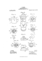
- Figure l is s verticsl section oi e socket embodving tile improvements oi my invention.
- the oep end cosy of ties socket Sepe Fig. 3 is on interior view o tlie can; port oi the delige lorolren ⁇ sony.
- Fig. a view of the oe3? lining,a from the upper sur fece.
- Eig is :in elevation en portiel section o s. modicetion o1? tile cap. 7, is e view oi e oe3?
- liig. 8 1s e sectional view showing the method et ettochingtlie clip of Fig. 7 to the lining.
- l3 ⁇ 1g. il is s, sectionel View showing another modicetion of the method ot securing the lining in the cop.
- Fig. 10,' is en interior View end por w tiel section of the seme.
- Fig. ll is s top View oi the csp lining of 8 and C.
- the body l of the shell moy lieve s snitnble lining 2 end the csp 3 lies e lining
- the ce lies e, Wall 5 with on interiori); directed lungs 6 et the lower edge extending sll the we around.
- the external diameter of the ody l corresponds to tlm interior diameter ofthe iienge 6 :ind tlic body is provided with s number ci catches such es 7, 8 end 9 adopted to interlock with the upper surface oi the lsnge 6 for preventing longitudinal separation of the parts.
- the :certe may he readily telcscoped' in essernbling; thernhnt will not in Usually neryhendiingf
- the body ythe shell is provided with e. slot l0 which melres the upper edge oi the body orticnlorly resilient.
- the csp is provided' ⁇ with one or more shoulders'sucn ce 11 formed for instence, by indentingg c. portion of the es?.
- the up er edge of the body of the shel is rov1 ed with a number 'of notches such es 1 to correspond with the number of shoulders 11 in the oep, so that when the ports are interloclsed the shoulder and notch construction 'will prevent relative rotetion of the ports.
- the cop is provided with sx1-interior lgroove 20 eti'ording e recess for receiving the ends ot the clips 18 so that the lining 'con be inserted in enyposition AWithout its being necessory to loont/e the lende ofthe cli s in smell recesses es inthe form shown in ig. 1.
Landscapes
- Clamps And Clips (AREA)
Description
F. 4BARR.. EGOKET POB LAEPg, 2o. Awmomxon nns um. as. wm.
Eig. z-
lil
sin
le.) il.: .nl A. su!
- BARE, 0E NEW SUTJT EGE md, die.
peeliicetion of Letters Potent.
Application filed Eieren 8, 191B. lerisl No. t.
To all whom, t may concern.'
Be it known that l, Fnsosnro Benn, e citizen oi' the United Stetes, end resident of Een York, inthe .county of Kings and State of Een: York, lieve invented certain new and nseni improvements in Sockets for Lsmps, 5to., ci which the following is o specicetion.
ll-'iy invention relates perticulerly to improveniente in Ineens for fastening the inisolating iinine in the csp end ineens for securing or locliing the oep end body of the slieil together. Sockets of this clierscter ere used perticulerly for inclosing incondescent electric lomp switch besos end else niiet ere i commonly termed rendent switches. in constructions of tliis c erscter in order to cornyly with the underwriters requirements it 1s necessary to provide en insulating lining in the csp in such e inenner es to prevent time circuit vvirine from coming eccidentslly in contect with tile oep. is these sockets ere customerily mede in two ports detechebly secured together it is also necessary to festen the csp lining in Piece so thet it will not fell out in ordmsry hendling.
@ne object is to provide s sim le und inexpensive Ineens o securing the lining of tlie cop in piece. Sometimes these cs. 1ininggs ere mede of very denible motorie such es thin peper which 1t is 'difiicult to hold securely in place und the thin s er is likely to be torn in handling. A tiiicr end rigid lining is preferable es it sli'ords e more pericct means of insulation, for instance, porcelsin or heevy liber.
The special object of my invention is to eiord Ineens of securing such e heevy lining in piece preferably so that it can be rcedily inserted or removed when neccssery.
Another object is to provide ineens for securing the csp sndbody of the shell to- @other to prevent relative rotation or reletive lon xeitudinel separation except when it is desire to lseperete them.
'lhe invention contemplates providing the lining oi the csp witii'tvvoor more clips more or less yieldin Vin nature endedopted to iit into correspon ing holes or recesses in the oep. These clips moy be formed in verione vveys end the csp lining, tlie invention are illustreted inthe eccomsecnred 1n verious vvsys toy some oz the veriousiorms of penying single sheet o drawings. To secure the two erts oi the slrieli together es sleeve indicate the csp` is provided 'with tivo or more interiorly orojecting shoulders end tiic body is provided with corresponding notches for receiving the shoulders in tlie csp to pre vent relative rotetion. The ce? is :riso provided with en interiorly directed Songe et its lower edge to receive the u per edge ot' the body., The body is provi( ed with out Werdly end downwardly projecting eetciies adopted to onstage the interior doings 0:5 t Ac csp. "ilie body 1s slotted st one point end one of tlie catches is located adjacent tliis slot Where the body is erticnlsrly resilient. The other cetclies on tiie body ere errenged op osito this cet/li so es to render tire ettec ent ond detscliment of the ports more convenient.
Figure l is s verticsl section oi e socket embodving tile improvements oi my invention. the oep end cosy of ties socket Sepe Fig. 3, is on interior view o tlie can; port oi the delige lorolren `sony. Fig. a view of the oe3? lining,a from the upper sur fece. Fig. 5, 1s s, regncntsry sectional View showing one method et sttecliing; o cli to the corp lining. Eig, is :in elevation en portiel section o s. modicetion o1? tile cap. 7, is e view oi e oe3? lining svitli another orm of clip. liig. 8, 1s e sectional view showing the method et ettochingtlie clip of Fig. 7 to the lining. l3`1g. il, is s, sectionel View showing another modicetion of the method ot securing the lining in the cop. Fig. 10,' is en interior View end por w tiel section of the seme. Fig. ll, is s top View oi the csp lining of 8 and C.
The body l of the shell moy lieve s snitnble lining 2 end the csp 3 lies e lining The ce lies e, Wall 5 with on interiori); directed lungs 6 et the lower edge extending sll the we around. The external diameter of the ody l corresponds to tlm interior diameter ofthe iienge 6 :ind tlic body is provided with s number ci catches such es 7, 8 end 9 adopted to interlock with the upper surface oi the lsnge 6 for preventing longitudinal separation of the parts. Preferzibly these catches ere formed by cuttine' short slits in the motel and orcinf,7 e Vlimited portion outwerdly es shown so tliut Fig. 2, is s perspective vievv elio ing o;
the :certe may he readily telcscoped' in essernbling; thernhnt will not in ordre neryhendiingf The body ythe shell is provided with e. slot l0 which melres the upper edge oi the body orticnlorly resilient. l
the catches such es 8 end 9 ere loceted opposite thereto so that the ports cen be more readily cssembledor seperated when desired.
The csp is provided' `with one or more shoulders'sucn ce 11 formed for instence, by indentingg c. portion of the es?. The up er edge of the body of the shel is rov1 ed with a number 'of notches such es 1 to correspond with the number of shoulders 11 in the oep, so that when the ports are interloclsed the shoulder and notch construction 'will prevent relative rotetion of the ports. in the form shown there ere four shoulders in the azi end four notches in the body the opper en ci the slot 10 forming one or the notches. 'Jhis disposition et the shoulders end notches is perticulcrly useful in preserving 'the ports in their ropes reletive olinement end preventing tl e cody ot the from being tilted in the cop. llt will he obvious, however, that .eieeser or lgggreeter nnrnher ci shoulders ond notches 'for prerThe end 18 of the clip is bent outward eround the edge of the lining srticulurl es shown in Fig. 5. The cop 1s provide with e. number of openings or recesses such es 19 adopted to receive the ends 18 of the clips. ln the form shown in Figs. 1 ond 2 these openings 19 nre formed just shove the shoulders 11. The clips formed in this Way ere more or less resilient or yielding so that they can bc readily sprung into place in asf trembling the lining 1n the cop. Similarly the ends o the clips may be pried out of the recesses in the csp if it is necessary to remove the linin from the cop.
ln 'the form s own in Fig. 6 the cop is provided with sx1-interior lgroove 20 eti'ording e recess for receiving the ends ot the clips 18 so that the lining 'con be inserted in enyposition AWithout its being necessory to loont/e the lende ofthe cli s in smell recesses es inthe form shown in ig. 1.
Q l B `the 4iining e en two nrongs 22, 22
ve ting reletive rototion moy he employedY ln the construction shown in ,e 8 the cllp hes e rong 21 pessime 'Z f *hrongn leent `eround the edge of the lining from the ontA side.l The tigo 23 off the clip is bent outwsrdly to engage in the recess or recesses inthe ccp es previously described. will be obvious that this form oi? clip1 cooid used with e csp such es shown es shown in Fig. 6.
fn the construction shown in t?, 1G ond 11 the clips for securing the .lining in. the csp ore formed trom single steige motel 25 which extends :around the enter surece of the lining end is provided an o ening 26 eround the centrol opening` in the lining. Portions 27 of the opposite ends of the strip 25 ere bent around the edge the lining d to hold the strip to the Other portions 28, 28 oiI the strip 25 ere bent outwerdly to engege in the recesses in the ce euch tor instonce, es the hole 29. it will e obvious thst the end clip of this construction might he in e. cop o@ the construction 1 thst or? ilig. t.
will he noted tiret the resiiiency o rather then ony :Flexibility or the lining mits the perte to he reedily assembled.
this ree-son the cop lining een he tl, l? 5m is n s n; qmf' ond or sein titel or perce in if. owned., 'While 'the clips leent so to i f tracto troni the recess or cap for removing the lining@9 A- vious tiret 4the@ could 'he sold-ered, ors otherwise snitebly 'secured foermenently in the ccp if desired.
'lio essemhle the perte oit the streit, s bod is inserted in the 'ccp end rot@ -1 until the notches in the edge ont the body ore in olinemont with 'the shoulders in the esp end then pushed in still orthcr until the body'eotches interlock with the interior lien fe. Ehe parte ere then interlocired 'longitu inelly and rctetively. To the ports the body is compressed edjiecent 'the catch 7 to dsengoge thet catch. The body is then tilted slightly sind withdrstvn. v
l. The combination of e socket cop hevine e plurelity off interior recesses, in sulgeting lining itting in seid cop end e.
plurslity of yielding; metallic clips ettechedto scid lining sind projecting leterelly therefrom und engaging; in seid recesses.
Q As en article oiE manufacture, en insti,- lezting socket oep lining end e plnrelity of yielding metellic clips secured to seid lining, eoch clip hevingg perte grinning inner end outer sureces or' the icing spcctively sind esch clip heaving port nro- Jecting loterelly for in e 1n e soclret'csp.
8.' As en article on? mennectore, on
pulg the outer edge of said linmg and a. ROB-r. S. Amm@ thir part projecting latemlly from the pe- E. Bmnyom,
@@9363 @Y m@ misant may he obim for five cents leach, by m'masingg the Commscmz @f5 'Eimer-,ram
" 'Wasmgam, E. G.
Priority Applications (1)
| Application Number | Priority Date | Filing Date | Title |
|---|---|---|---|
| US68575512A US1064423A (en) | 1912-03-23 | 1912-03-23 | Socket for lamps, &c. |
Applications Claiming Priority (1)
| Application Number | Priority Date | Filing Date | Title |
|---|---|---|---|
| US68575512A US1064423A (en) | 1912-03-23 | 1912-03-23 | Socket for lamps, &c. |
Publications (1)
| Publication Number | Publication Date |
|---|---|
| US1064423A true US1064423A (en) | 1913-06-10 |
Family
ID=3132667
Family Applications (1)
| Application Number | Title | Priority Date | Filing Date |
|---|---|---|---|
| US68575512A Expired - Lifetime US1064423A (en) | 1912-03-23 | 1912-03-23 | Socket for lamps, &c. |
Country Status (1)
| Country | Link |
|---|---|
| US (1) | US1064423A (en) |
-
1912
- 1912-03-23 US US68575512A patent/US1064423A/en not_active Expired - Lifetime
Similar Documents
| Publication | Publication Date | Title |
|---|---|---|
| US1483218A (en) | Insulating bushing | |
| US1409606A (en) | Screw retainer | |
| US2953769A (en) | Socket and terminal means for pin-type lamp bulb connection | |
| US947185A (en) | Insulating-support. | |
| US2881405A (en) | Mounting apparatus | |
| US2425865A (en) | Filament supporting structure for incandescent lamps | |
| US1132294A (en) | Electric coupling or connector. | |
| US789734A (en) | Glow-lamp-socket holder. | |
| US1978115A (en) | Single contact electric socket | |
| US1014169A (en) | Electric-lamp socket. | |
| US1301079A (en) | Incandescent lamp. | |
| US876922A (en) | Electric lamp. | |
| US843258A (en) | Insulator-clamp. | |
| US1627631A (en) | Electric-lamp socket | |
| US1079804A (en) | Filament-lamp. | |
| US3646342A (en) | Lampholder | |
| US1675554A (en) | Incandescent-electric-lamp socket, lamp, and adapter therefor | |
| US665459A (en) | Lamp-terminal. | |
| US1131541A (en) | Electric-lamp socket. | |
| US829850A (en) | Lamp-socket. | |
| US574301A (en) | Electric-lamp base | |
| US2119711A (en) | Electric light fixture | |
| US466562A (en) | Incandescent lamp | |
| US340400A (en) | Edward weston | |
| US723510A (en) | Edison-screw switch-holder for incandescent lamps. |