US1064100A - Tire-protector. - Google Patents
Tire-protector. Download PDFInfo
- Publication number
- US1064100A US1064100A US67118412A US1912671184A US1064100A US 1064100 A US1064100 A US 1064100A US 67118412 A US67118412 A US 67118412A US 1912671184 A US1912671184 A US 1912671184A US 1064100 A US1064100 A US 1064100A
- Authority
- US
- United States
- Prior art keywords
- protector
- tire
- strips
- longitudinal
- transverse
- Prior art date
- Legal status (The legal status is an assumption and is not a legal conclusion. Google has not performed a legal analysis and makes no representation as to the accuracy of the status listed.)
- Expired - Lifetime
Links
Images
Classifications
-
- B—PERFORMING OPERATIONS; TRANSPORTING
- B60—VEHICLES IN GENERAL
- B60C—VEHICLE TYRES; TYRE INFLATION; TYRE CHANGING; CONNECTING VALVES TO INFLATABLE ELASTIC BODIES IN GENERAL; DEVICES OR ARRANGEMENTS RELATED TO TYRES
- B60C11/00—Tyre tread bands; Tread patterns; Anti-skid inserts
- B60C11/02—Replaceable treads
Definitions
- the object of the present invention is to provide a tire protector, adapted to resist puncture of the tire, and so constructed that, when the tire is inflated, the protector will automatically grip the tire.
- a further object of the invention is to provide a tire protector, consisting of interwoven strips means being provided for holding the. strips together, and means being provided for holding the ends of the protector together.
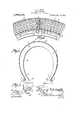
- Figuro 1 shows in side elevation, a portion of a tire equipped with the protector constructed in accordance with the present invention, parts of the protector being broken away;
- Fig. 2 is a transverse section;
- Fig. 3 is a fragmental perspective showing the means whereby the adjacent, meeting ends of the protector are held together.
- a series of longitudinal strips 1 and 8 are provided, these strips being of sutlicient length to extend entirely around the wheel, circumferent-ially of the same.
- the transverse strips 2, as best shown in Fig. 1, taper, toward their ends, so that theprotector will assume a trough-like form.
- the strips 1 and 2 are preferably fashioned from resilient metal.
- the strips 1 and 2 are united by securing elements 3, which may be rivets.
- the number of rivets may be increased or decreased, from the showing of the drawings, as the exigencies of the case may dictate.
- the extremities of the rivets 3 outstand beyond the tread surface of the protector, so as to form an effective anti-slipping means.
- alternate transverse strips 2 only terminate in binder-receiving elements, preferably taking the form of hooks 4 which hooks 4 fit into the bead 5 of the tire 6, the hooks receiving the-securing rings 7, whereby the protector is held upon the tire.
- Those longitudinal strips 8 which lie at the extreme lateral edges of the protector, are (11sposed beneath the ends of said alternate transverse strips 2, so as to receive the inward thrust of the ends of the said trans verse strips 2, thereby to protect the the '6 against injury from the hooked, free ends of the transverse strips.
- each longitudinal strip 1 terminates in a key-hole slot 11 and the other end 10 of each longitudinal strip is provided with a headed stud 12.
- the head of the stud 12 will pass freely through the larger portion of the key-hole slot 11, and the neck of the stud 12 will register in the contracted portion of the slot 11.
- the ends 9 and 10 ot' the longitudinal strips 1, preferably protrude beyond those transverse strips 14 which are adjacent the ends of the protector.
- a tire protector consisting of longitudinal and transverse strips closely interwoven, the transverse strips tapering toward their free ends and alternate ones only of the transverse strips terminating in outstanding, my own, I have hereto aflixed my signature blnder-receivlng elements, the longitudinal in the presence of two witnesseses.
Landscapes
- Engineering & Computer Science (AREA)
- Mechanical Engineering (AREA)
- Tires In General (AREA)
Description
G. A. SMITH.
TIRE PROTECTOR. APPLICATION IILBD JAN.15,1912.
1,064,100, Patented June 10, 1913.
o 9 o o Q Q o 0 m 0 0 Q o o 0 0 o o o Attrneys CLIFTON A. SMITH, OF NEW ORLEANS, LOUISIANA.
TIRE-PROTECTOR.
Specification of Letters Patent.
Patented June 10, 1913.
Application filed January 15, 1912. Serial No. 671,184.
State of Louisiana, have invented a new and useful Tire-Protector, of which the fol-.
lowing is a specification.
The object of the present invention is to provide a tire protector, adapted to resist puncture of the tire, and so constructed that, when the tire is inflated, the protector will automatically grip the tire.
A further object of the invention is to provide a tire protector, consisting of interwoven strips means being provided for holding the. strips together, and means being provided for holding the ends of the protector together.
With the foregoing and other objects in view, which will appear as the description proceeds, the invention resides in the combination and arrangement of parts and in the details of construction hereinafter described and claimed, it being understood that changes in the precise embodiment of invention herein disclosed can be made within the scope of what is claimed without departing from the spirit of the invention.
In the accompanying drawings,Figuro 1 shows in side elevation, a portion of a tire equipped with the protector constructed in accordance with the present invention, parts of the protector being broken away; Fig. 2 is a transverse section; and Fig. 3 is a fragmental perspective showing the means whereby the adjacent, meeting ends of the protector are held together.
In carrying out the invention, a series of longitudinal strips 1 and 8 are provided, these strips being of sutlicient length to extend entirely around the wheel, circumferent-ially of the same. Disposed approximately at right angles to the longitudinal strips 1 and 8, are transverse strips 2, interwoven with the strips 1 and 8. The transverse strips 2, as best shown in Fig. 1, taper, toward their ends, so that theprotector will assume a trough-like form. The strips 1 and 2 are preferably fashioned from resilient metal. At their points of crossing, the strips 1 and 2 are united by securing elements 3, which may be rivets. The number of rivets may be increased or decreased, from the showing of the drawings, as the exigencies of the case may dictate. The extremities of the rivets 3 outstand beyond the tread surface of the protector, so as to form an effective anti-slipping means.
The ends of alternate transverse strips 2 only terminate in binder-receiving elements, preferably taking the form of hooks 4 which hooks 4 fit into the bead 5 of the tire 6, the hooks receiving the-securing rings 7, whereby the protector is held upon the tire. Those longitudinal strips 8 which lie at the extreme lateral edges of the protector, are (11sposed beneath the ends of said alternate transverse strips 2, so as to receive the inward thrust of the ends of the said trans verse strips 2, thereby to protect the the '6 against injury from the hooked, free ends of the transverse strips.
One end 9 of each longitudinal strip 1 terminates in a key-hole slot 11 and the other end 10 of each longitudinal strip is provided with a headed stud 12. The head of the stud 12 will pass freely through the larger portion of the key-hole slot 11, and the neck of the stud 12 will register in the contracted portion of the slot 11. The ends 9 and 10 ot' the longitudinal strips 1, preferably protrude beyond those transverse strips 14 which are adjacent the ends of the protector.
In practical operation, when the tire 6 is inflated, the hooks 4 will be made to engage with the rings (3, and at the same time, the protector will be expanded longitudinally, causing the studs 12 to fit closely, and against accidental displacement, in the key hole slots 11, it being obvious that when the tire (i is inflated, the protector will be completely and closely filled by the tire.
Having thus described the invention, what is claimed is A tire protector consisting of longitudinal and transverse strips closely interwoven, the transverse strips tapering toward their free ends and alternate ones only of the transverse strips terminating in outstanding, my own, I have hereto aflixed my signature blnder-receivlng elements, the longitudinal in the presence of two Witnesses.
strips which lie at the extreme lateral ed es i of the protector being disposed beneath the l CLIB TON SMITH 5 ends of the said alternate transverse strips Witnesses:
to rereive the thrust of the binder. A. M. BUCI-IMANN,
In testimony that I claim the foregoing as W. M. LAWTON.
Priority Applications (1)
| Application Number | Priority Date | Filing Date | Title |
|---|---|---|---|
| US67118412A US1064100A (en) | 1912-01-15 | 1912-01-15 | Tire-protector. |
Applications Claiming Priority (1)
| Application Number | Priority Date | Filing Date | Title |
|---|---|---|---|
| US67118412A US1064100A (en) | 1912-01-15 | 1912-01-15 | Tire-protector. |
Publications (1)
| Publication Number | Publication Date |
|---|---|
| US1064100A true US1064100A (en) | 1913-06-10 |
Family
ID=3132344
Family Applications (1)
| Application Number | Title | Priority Date | Filing Date |
|---|---|---|---|
| US67118412A Expired - Lifetime US1064100A (en) | 1912-01-15 | 1912-01-15 | Tire-protector. |
Country Status (1)
| Country | Link |
|---|---|
| US (1) | US1064100A (en) |
-
1912
- 1912-01-15 US US67118412A patent/US1064100A/en not_active Expired - Lifetime
Similar Documents
| Publication | Publication Date | Title |
|---|---|---|
| US1127517A (en) | Vehicle-tire. | |
| US1001079A (en) | Package-tie. | |
| US923456A (en) | Antislip device. | |
| US1399430A (en) | Segmental casing for tires | |
| US1244080A (en) | Non-skid tire-protector. | |
| US1419680A (en) | Antiskidding device | |
| US1111404A (en) | Protector for tires. | |
| US2130658A (en) | Tire patch | |
| US937812A (en) | Tire-armor. | |
| US1103396A (en) | Tire-armor. | |
| US1821964A (en) | Packing | |
| US1436102A (en) | Tire shield | |
| US1371956A (en) | Antiskid device | |
| US911427A (en) | Chain mat for wheel-tires. | |
| US1265486A (en) | Chain-lock. | |
| US1181498A (en) | Spring-tire. | |
| US538361A (en) | Tire and felly clamp | |
| US611375A (en) | Chusetts | |
| US1338522A (en) | Cleat for barrels | |
| US1487163A (en) | Antiskid device | |
| US1147182A (en) | Antiskidding device. | |
| US1427294A (en) | Roof ladder | |
| US967979A (en) | Tire-protector. | |
| US948193A (en) | Pneumatic tire for vehicles. | |
| US503846A (en) | Detachable tire |