US10636599B2 - Multifunction wireless relay - Google Patents
Multifunction wireless relay Download PDFInfo
- Publication number
- US10636599B2 US10636599B2 US15/829,513 US201715829513A US10636599B2 US 10636599 B2 US10636599 B2 US 10636599B2 US 201715829513 A US201715829513 A US 201715829513A US 10636599 B2 US10636599 B2 US 10636599B2
- Authority
- US
- United States
- Prior art keywords
- printed circuit
- circuit board
- settings
- wireless
- relay
- Prior art date
- Legal status (The legal status is an assumption and is not a legal conclusion. Google has not performed a legal analysis and makes no representation as to the accuracy of the status listed.)
- Active
Links
- 230000006854 communication Effects 0.000 claims abstract description 29
- 238000004891 communication Methods 0.000 claims abstract description 29
- 230000006870 function Effects 0.000 claims description 15
- 238000012545 processing Methods 0.000 claims description 7
- 238000000819 phase cycle Methods 0.000 claims description 4
- 239000011248 coating agent Substances 0.000 description 6
- 238000000576 coating method Methods 0.000 description 6
- 230000001934 delay Effects 0.000 description 6
- 238000004519 manufacturing process Methods 0.000 description 6
- 230000008878 coupling Effects 0.000 description 3
- 238000010168 coupling process Methods 0.000 description 3
- 238000005859 coupling reaction Methods 0.000 description 3
- 238000000034 method Methods 0.000 description 3
- 230000007175 bidirectional communication Effects 0.000 description 2
- 238000011109 contamination Methods 0.000 description 2
- 230000003111 delayed effect Effects 0.000 description 2
- 238000013461 design Methods 0.000 description 2
- 230000001960 triggered effect Effects 0.000 description 2
- 238000006243 chemical reaction Methods 0.000 description 1
- 230000009977 dual effect Effects 0.000 description 1
- 238000005516 engineering process Methods 0.000 description 1
- 239000000463 material Substances 0.000 description 1
- 238000012986 modification Methods 0.000 description 1
- 230000004048 modification Effects 0.000 description 1
- 238000012544 monitoring process Methods 0.000 description 1
- 238000004353 relayed correlation spectroscopy Methods 0.000 description 1
- 230000000717 retained effect Effects 0.000 description 1
- 239000004065 semiconductor Substances 0.000 description 1
- 230000009131 signaling function Effects 0.000 description 1
- 239000000126 substance Substances 0.000 description 1
- XLYOFNOQVPJJNP-UHFFFAOYSA-N water Substances O XLYOFNOQVPJJNP-UHFFFAOYSA-N 0.000 description 1
Images


Classifications
-
- H—ELECTRICITY
- H01—ELECTRIC ELEMENTS
- H01H—ELECTRIC SWITCHES; RELAYS; SELECTORS; EMERGENCY PROTECTIVE DEVICES
- H01H47/00—Circuit arrangements not adapted to a particular application of the relay and designed to obtain desired operating characteristics or to provide energising current
- H01H47/001—Functional circuits, e.g. logic, sequencing, interlocking circuits
-
- H—ELECTRICITY
- H02—GENERATION; CONVERSION OR DISTRIBUTION OF ELECTRIC POWER
- H02H—EMERGENCY PROTECTIVE CIRCUIT ARRANGEMENTS
- H02H1/00—Details of emergency protective circuit arrangements
- H02H1/0061—Details of emergency protective circuit arrangements concerning transmission of signals
-
- H—ELECTRICITY
- H02—GENERATION; CONVERSION OR DISTRIBUTION OF ELECTRIC POWER
- H02H—EMERGENCY PROTECTIVE CIRCUIT ARRANGEMENTS
- H02H3/00—Emergency protective circuit arrangements for automatic disconnection directly responsive to an undesired change from normal electric working condition with or without subsequent reconnection ; integrated protection
- H02H3/006—Calibration or setting of parameters
-
- H—ELECTRICITY
- H02—GENERATION; CONVERSION OR DISTRIBUTION OF ELECTRIC POWER
- H02H—EMERGENCY PROTECTIVE CIRCUIT ARRANGEMENTS
- H02H7/00—Emergency protective circuit arrangements specially adapted for specific types of electric machines or apparatus or for sectionalised protection of cable or line systems, and effecting automatic switching in the event of an undesired change from normal working conditions
- H02H7/08—Emergency protective circuit arrangements specially adapted for specific types of electric machines or apparatus or for sectionalised protection of cable or line systems, and effecting automatic switching in the event of an undesired change from normal working conditions for dynamo-electric motors
- H02H7/0833—Emergency protective circuit arrangements specially adapted for specific types of electric machines or apparatus or for sectionalised protection of cable or line systems, and effecting automatic switching in the event of an undesired change from normal working conditions for dynamo-electric motors for electric motors with control arrangements
-
- H—ELECTRICITY
- H04—ELECTRIC COMMUNICATION TECHNIQUE
- H04B—TRANSMISSION
- H04B7/00—Radio transmission systems, i.e. using radiation field
- H04B7/14—Relay systems
- H04B7/15—Active relay systems
-
- H—ELECTRICITY
- H04—ELECTRIC COMMUNICATION TECHNIQUE
- H04B—TRANSMISSION
- H04B7/00—Radio transmission systems, i.e. using radiation field
- H04B7/14—Relay systems
- H04B7/15—Active relay systems
- H04B7/155—Ground-based stations
- H04B7/15557—Selecting relay station operation mode, e.g. between amplify and forward mode, decode and forward mode or FDD - and TDD mode
-
- H—ELECTRICITY
- H05—ELECTRIC TECHNIQUES NOT OTHERWISE PROVIDED FOR
- H05K—PRINTED CIRCUITS; CASINGS OR CONSTRUCTIONAL DETAILS OF ELECTRIC APPARATUS; MANUFACTURE OF ASSEMBLAGES OF ELECTRICAL COMPONENTS
- H05K1/00—Printed circuits
- H05K1/02—Details
- H05K1/14—Structural association of two or more printed circuits
- H05K1/148—Arrangements of two or more hingeably connected rigid printed circuit boards, i.e. connected by flexible means
-
- H—ELECTRICITY
- H05—ELECTRIC TECHNIQUES NOT OTHERWISE PROVIDED FOR
- H05K—PRINTED CIRCUITS; CASINGS OR CONSTRUCTIONAL DETAILS OF ELECTRIC APPARATUS; MANUFACTURE OF ASSEMBLAGES OF ELECTRICAL COMPONENTS
- H05K7/00—Constructional details common to different types of electric apparatus
- H05K7/14—Mounting supporting structure in casing or on frame or rack
- H05K7/1422—Printed circuit boards receptacles, e.g. stacked structures, electronic circuit modules or box like frames
- H05K7/1427—Housings
-
- H—ELECTRICITY
- H02—GENERATION; CONVERSION OR DISTRIBUTION OF ELECTRIC POWER
- H02H—EMERGENCY PROTECTIVE CIRCUIT ARRANGEMENTS
- H02H7/00—Emergency protective circuit arrangements specially adapted for specific types of electric machines or apparatus or for sectionalised protection of cable or line systems, and effecting automatic switching in the event of an undesired change from normal working conditions
- H02H7/08—Emergency protective circuit arrangements specially adapted for specific types of electric machines or apparatus or for sectionalised protection of cable or line systems, and effecting automatic switching in the event of an undesired change from normal working conditions for dynamo-electric motors
-
- H—ELECTRICITY
- H05—ELECTRIC TECHNIQUES NOT OTHERWISE PROVIDED FOR
- H05K—PRINTED CIRCUITS; CASINGS OR CONSTRUCTIONAL DETAILS OF ELECTRIC APPARATUS; MANUFACTURE OF ASSEMBLAGES OF ELECTRICAL COMPONENTS
- H05K1/00—Printed circuits
- H05K1/02—Details
- H05K1/14—Structural association of two or more printed circuits
- H05K1/144—Stacked arrangements of planar printed circuit boards
-
- H—ELECTRICITY
- H05—ELECTRIC TECHNIQUES NOT OTHERWISE PROVIDED FOR
- H05K—PRINTED CIRCUITS; CASINGS OR CONSTRUCTIONAL DETAILS OF ELECTRIC APPARATUS; MANUFACTURE OF ASSEMBLAGES OF ELECTRICAL COMPONENTS
- H05K2201/00—Indexing scheme relating to printed circuits covered by H05K1/00
- H05K2201/04—Assemblies of printed circuits
- H05K2201/042—Stacked spaced PCBs; Planar parts of folded flexible circuits having mounted components in between or spaced from each other
-
- H—ELECTRICITY
- H05—ELECTRIC TECHNIQUES NOT OTHERWISE PROVIDED FOR
- H05K—PRINTED CIRCUITS; CASINGS OR CONSTRUCTIONAL DETAILS OF ELECTRIC APPARATUS; MANUFACTURE OF ASSEMBLAGES OF ELECTRICAL COMPONENTS
- H05K2201/00—Indexing scheme relating to printed circuits covered by H05K1/00
- H05K2201/10—Details of components or other objects attached to or integrated in a printed circuit board
- H05K2201/10007—Types of components
- H05K2201/10159—Memory
-
- H—ELECTRICITY
- H05—ELECTRIC TECHNIQUES NOT OTHERWISE PROVIDED FOR
- H05K—PRINTED CIRCUITS; CASINGS OR CONSTRUCTIONAL DETAILS OF ELECTRIC APPARATUS; MANUFACTURE OF ASSEMBLAGES OF ELECTRICAL COMPONENTS
- H05K2201/00—Indexing scheme relating to printed circuits covered by H05K1/00
- H05K2201/10—Details of components or other objects attached to or integrated in a printed circuit board
- H05K2201/10227—Other objects, e.g. metallic pieces
- H05K2201/10363—Jumpers, i.e. non-printed cross-over connections
Definitions
- the present disclosure generally relates to a relay. More particularly, the present disclosure generally relates to a relay that is enabled for radio frequency communication, such as Bluetooth wireless communication.
- Relays are required to perform a variety of different functions depending on the applications for which they are employed. For example, some relays preform various timing functions. In one example, a relay commences timing when an initiate contact is closed and have an off output during timing. In another example, a relay commences timing when an initiate contact is open and have an on output during timing. In yet another example, a type of relay has an output that switches between an off and on state during timing. Furthermore, relays are adapted for use in all different classes of electrical circuits including low voltage DC, high voltage DC, low voltage AC, and high voltage AC.
- motor protection relay One type of protection relay is a motor protection relay, where motor protection relays are generally used to provide such monitoring and protection functions.
- Motors are widely used throughout industry to transform electrical energy into mechanical energy that may be used to perform work. Motors are often necessary pieces of equipment for performing numerous industrial tasks. Because motors are such an integral part of many industries, loss of use of a motor can cause significant delays and loss of income while the motor is off-line. Therefore, motors are often monitored and protected against overload conditions, ground faults, and the like.
- relays may have different time delay functions and settings. Some relays have fixed time delays while other relays have adjustable time delays. Relays that have adjustable time delays have specified timing ranges while relays that have fixed time delays have specified time delays.
- these uniquely configured relays often include numerous physical interfaces, such as adjustment knobs, that require adjustment before the relays are used in the field and/or while the relays are deployed in the field.
- the programming and configuration interfaces physically located on conventional relays have a number of drawbacks. For example, adjusting or modifying programming and configuration interfaces located on the conventional relays necessarily requires a user or technician to physically access the relays. This requirement to physically access the relays to make adjustments and configuration settings is intrinsically time-consuming. Furthermore, physically accessing the relays to make adjustments and configuration settings when the relays are deployed in the field may expose the user or technician to unnecessary safety hazards. Such safety hazards include exposure to high voltages, arc flashes, and the like, which may be present in environments where conventional relays are deployed. Furthermore, physical interfaces on the conventional relays may be subject to failure due to mechanical abuse, moisture, and other forms of contamination. Therefore, an improved programming and configuration interface for relays is needed.
- a wireless relay may include a housing; an output, disposed within the housing; and a wireless interface, disposed within the housing, wherein the wireless interface is to receive wireless communication signals including settings to configure one or more functionalities associated with the protection relay.
- a multifunction wireless relay may include a housing and an output disposed within the housing.
- the multifunction wireless relay may also include a processor, disposed within the housing and coupled to the output; and an antenna, coupled to the processor, wherein the antenna enables wireless connectivity to program functionality of the multifunction wireless relay.
- a wireless relay may include a housing; an output, disposed within the housing; and a wireless communications interface, coupled to the output and disposed within the housing, the wireless communication interface adapted to receive wireless communication signals for configuring operating parameters of the protection relay via the processor, wherein the wireless relay is devoid of a physical user interface located within, or on an exterior of, the housing.
- a protection relay may include a housing and a printed circuit board disposed within the housing.
- the printed circuit board may include a processor and a wireless communication interface, the wireless communication interface adapted to receive wireless communication signals for configuring operating parameters of the protection relay via the processor, wherein the protection relay is devoid of a physical user interface located within, or on an exterior of, the housing.
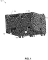
- FIG. 1 illustrates a motor protection relay, according to an embodiment of the disclosure
- FIG. 2 illustrates a printed circuit board that may be housed within a housing of the motor protection relay, according to an embodiment of the disclosure.
- FIG. 3 illustrates an exemplary view of the printed circuit board, according to an embodiment of the disclosure.
- FIG. 4 illustrates an exemplary computing device wirelessly communicating with the motor protection relay, according to an embodiment of the disclosure.
- FIG. 5 illustrates a relay according to an embodiment of the disclosure.
- the present embodiments provide enhanced relays, such as multifunction relays, protection relays, including motor protection relays, where operation of the relays is enhanced via a wireless interface.
- FIG. 1 illustrates a motor protection relay 100 according to an embodiment of the disclosure.
- the motor protection relay 100 includes a housing 102 .
- the housing 102 includes a plurality of voltage inputs 104 .
- a motor (not illustrated) may be coupled to the motor protection relay 100 using one or more of the voltage inputs 104 .
- the housing 102 of the motor protection relay 100 includes one or more outputs 106 .
- the outputs 106 may include, for example, alarm outputs for indicating a fault associated with a motor coupled to the motor protection relay 100 .
- the motor protection relay 100 may further include one or more integrated current transformers 108 .
- the motor protection relay 100 may include one or more additional inputs and outputs 110 .
- Such one or more additional inputs and outputs 110 may include, for example, auxiliary programmable inputs for the motor protection relay 100 , zero-sequence ground fault current transformer connectivity for direct or resistive grounded power systems, and/or network coupling for input output devices, displays, and the like.
- the motor protection relay 100 may include an Ethernet port 112 .
- the Ethernet port 112 enables a wired coupling of a computing device to the motor protection relay 100 for the purpose of data acquisition, control, or programming of various set points associated with the motor protection relay 100 .
- the motor protection relay 100 does not include a physical configuration interface on the housing 102 . Rather, as will be described in the following, the motor protection relay 100 may be monitored, controlled or programmed using a computing device, such as a tablet computer or mobile phone, wirelessly coupled to the motor protection relay 100 . To that end, internal components of the motor protection relay 100 may enable wireless connectivity to external computing devices. Such wireless connectivity functionality associated with the motor protection relay 100 may include Bluetooth, Wi-Fi, ZigBee, near field wireless communication protocols, or other short range, medium-range or long-range wireless connectivity functionality.
- FIG. 2 illustrates a printed circuit board 200 that may be housed within the housing 102 of the motor protection relay 100 , according to an embodiment of the disclosure.
- the printed circuit board 200 includes a first printed circuit board section 202 , a second printed circuit board section 204 , and a third printed circuit board section 206 .
- the printed circuit board 200 further includes a first flexible interconnect element 208 that couples the first printed circuit board section 202 to the third printed circuit board section 206 .
- a second flexible interconnect element 210 is included that couples the second printed circuit board section 204 to the third printed circuit board section 206 .
- the first flexible interconnect element 208 may include one or more wired connections that enable bidirectional communication between the first printed circuit board section 202 and the third printed circuit board section 206 .
- the second flexible interconnect element 210 may include one or more wired connections that enable bidirectional communication between the second printed circuit board section 204 and the third printed circuit board section 206 .
- the printed circuit board 200 includes two rigid printed board sections that are coupled together using a flexible interconnect element.
- the printed circuit board 200 may be configured in a compact arrangement, as is illustrated in FIG. 2 .
- the first flexible interconnect element 208 and the second flexible interconnect element 210 allow the folding of the printed circuit board 200 in the illustrated compact arrangement.
- this compact arrangement of the printed circuit board 200 provides a streamlined design that reduces a size of the housing 102 compared to a size of a housing that would be required to house a single rigid printed circuit board, or multiple rigid printed circuit boards in a stacked arrangement.
- FIG. 3 illustrates an exemplary view of the printed circuit board 200 , according to an embodiment of the disclosure.
- the printed circuit board 200 is illustrated in an extended or generally horizontal arrangement.
- the extended or generally horizontal arrangement of the printed circuit board 200 is made possible at least in part by the first flexible interconnect element 208 and second flexible interconnect element 210 .
- the printed circuit board 200 includes a wireless radio frequency module 300 .
- the wireless radio frequency module 300 may include wireless protocol functionality enabling Bluetooth, Wi-Fi, ZigBee, near field wireless communication protocols, and/or other short range, medium-range or long-range wireless connectivity functionality.
- the wireless radio frequency module 300 accommodates wireless connectivity to a computing device, such as a tablet computer or mobile phone.
- a computing device may be used to configure motor protection settings of the motor protection relay 100 .
- Such settings may include, but are not limited to, inverse or instantaneous phase overcurrent protection settings, phase to phase protection settings, phase unbalance protection settings, ground fault protection settings, motor jam protection settings, underload or under power protection settings, off-nominal frequency protection settings, out of phase sequence condition settings, motor backspin settings, emergency motor override settings, current transformer settings, and the like.
- the printed circuit board 200 may include various additional electronic components disposed thereon.
- the printed circuit board 200 may include a first output relay 302 and a second output relay 304 .
- a central processing unit 306 may be disposed on the printed circuit board 200 .
- the central processing unit 306 may be used to enable various functionalities associated with the motor protection relay 100 .
- the central processing unit 306 may execute a sequence of stored instructions to enable the various functionalities associated with the motor protection relay 100 .
- the central processing unit 306 processes wireless communication signals of the wireless radio frequency module 300 .
- Those wireless communication signals may include settings used to configure the motor protection relay 100 .
- the settings may be wirelessly transmitted from an external computer device and received by the wireless radio frequency module 300 .
- An analog-to-digital converter 308 is provided for mixed signal functions of components disposed on the printed circuit board 200 .
- DC to DC converters 310 and 312 are provided to handle DC voltage level conversions.
- a conformal coating 314 may be applied over or to cover the printed circuit board 200 and the electrical components disposed thereon.
- the conformal coating 314 is a polymeric film that covers a surface of the printed circuit board 200 as well as the components disposed on the printed circuit board 200 .
- the conformal coating 314 is advantageously used to protect the printed circuit board 200 and the components disposed thereon from undesirable external influences, such as water, chemicals, undesirable conductive contamination, and the like. It should be noted here that printed circuit boards associated with a conventional motor protection relays are unable to accommodate such a conformal coating. Specifically, use of a conformal coating is generally not possible because of the programming and configuration interface physically located on conventional motor protection relays. Such a physical configuration interface requires multiple coupling points to the printed circuit boards, which makes applying a conformal coating to the printed circuit boards impracticable.
- FIG. 4 illustrates an exemplary computing device 400 wirelessly communicating with the motor protection relay 100 .
- the exemplary computing device 400 includes a configuration interface 402 .
- the configuration interface 402 may be used to configure settings associated with the motor protection relay 100 .
- the configuration interface 402 may be used configure voltage settings, current settings, inverse or instantaneous phase overcurrent protection settings, phase to phase protection settings, phase unbalance protection settings, ground fault protection settings, motor jam protection settings, underload or under power protection settings, off-nominal frequency protection settings, out of phase sequence condition settings, motor backspin settings, emergency motor override settings, current transformer settings, and the like, which are configurable in the motor protection relay 100 .
- FIG. 5 illustrates a relay 500 according to an embodiment of the disclosure.
- the relay 500 is a multifunction relay.
- the relay 500 may be a time delay relay that includes selectable single and dual functions.
- the relay 500 may receive configuration and programming settings via a wireless connection, such as via Bluetooth, infrared, ZigBee, near field wireless communication protocols, or other short range, medium-range or long-range wireless connection. Therefore, unlike the conventional relays, the requirement to include switches, potentiometers or other mechanical hardware on an exterior housing of the relay 500 is eliminated.
- the relay 500 may include a housing 502 .
- the housing 502 may include a power supply 504 , a microprocessor 506 and an output stage 508 .
- the power supply 504 may include one or more leads or input ports 510 that are accessible from an exterior of the housing 502 .
- the input ports 510 may couple to a power source.
- the power supply 504 may be functional to convert a voltage supplied by the power source. For example, the power supply 504 may convert an AC voltage to a DC voltage.
- the output stage 508 may include one or more leads or output ports 512 .
- the output ports 512 are in the form of a pin octal socket.
- the output ports 512 may be associated with an 8 or 11 pin octal socket.
- the microprocessor 506 may be coupled to an antenna 514 .
- the antenna 514 enables wireless connectivity to a device that may be used to program the functionality of the relay 500 .
- the wireless connectivity compatible with the microprocessor 506 includes Bluetooth, infrared, ZigBee, near field wireless communication protocols, or other short range, medium-range or long-range wireless connection.
- the microprocessor 506 may include a wireless module, as generally described above, or may be coupled to a wireless module, where the microprocessor 506 , wireless module, and antenna 514 enable wireless communications to receive instructions for programming functionality of the relay 500 .
- a wireless interface may be distributed within one or more components, including general processors, wireless chips, and so forth, to provide wireless functionality to a relay, such as relay 500 , including one or more wireless communications protocols, as known in the art.
- a central processor, and a communications processor used for wireless communications may be incorporated in a common chip (semiconductor die), acting as a wireless interface.
- the microprocessor 506 and antenna 514 may constitute a wireless interface in some embodiments.
- a disable component may be provided to allow disabling as well as enabling of wireless communications to and from a relay, such as motor protection relay 100 or relay 500 .
- a mechanical switch or jumper 516 associated with the microprocessor 506 is provided as a disable component.
- the jumper 516 may be located on a printed circuit board on which the microprocessor 506 is mounted.
- the jumper 516 may be used to disable the antenna 514 via the microprocessor 506 . More particularly, in one implementation, when the jumper 516 is in place, the microprocessor 506 is configured to allow for wireless communication via the antenna 514 .
- the microprocessor 506 is hardware and/or software configured without wireless communication functionality. Specifically, when the jumper 516 is removed, the antenna 514 and microprocessor 506 are unable to wirelessly configure the relay 500 .
- the relay 500 is wirelessly configured at the time of manufacture. Subsequently, the jumper 516 is removed to disconnect the antenna 514 from microprocessor 506 . This process of removing the jumper 516 removes the possibility of programming the relay 500 after manufacture.
- the relay 500 is wirelessly configured at the time manufacture, and the jumper 516 is left in place thereafter. Therefore, the wireless programming of the relay 500 after manufacture is retained, so that the relay 500 may be programmed in the field.
- the jumper 516 is shown as providing the functionality to enable or disable the wireless configurability functions of the relay 500 , it is to be recognized that the relay 500 may implement other technology for use as a disable component to enable or disable the wireless configurability functions to the relay 500 .
- the microprocessor 506 may be programmed to receive a predetermined code that enables or disables the wireless configurability functions of the relay 500 .
- the enable device in this case may be a code or other stored information, where such stored information may be stored in a memory located within microprocessor 506 or coupled to microprocessor 506 .
- the relay 500 may receive a vast number configuration instructions wirelessly via the antenna 514 .
- these configuration instructions configure the microprocessor to provide certain functionalities to the relay 500 .
- the configuration instructions may include, for example, delay on functions, such as delay on make and delay on operate; interval on; off delay, such as delay on release, delay on break, delay on deenergization; single shot, such as one-shot momentary interval; flasher, such as off a first are on first; on/off delay; single shot falling edge; watchdog, such a retriggerable single shot; triggered on delay; repeat cycle, such as off first or on first; delayed interval; triggered delayed interval; true off delay; on delay/true off delay; single shot-flasher; and/or on delay-flasher.
- the relay 500 may be programmed using a configuration interface on a computing device, tablet computer, and/or mobile device.
Landscapes
- Engineering & Computer Science (AREA)
- Microelectronics & Electronic Packaging (AREA)
- Computer Networks & Wireless Communication (AREA)
- Signal Processing (AREA)
- Physics & Mathematics (AREA)
- Electromagnetism (AREA)
- Emergency Protection Circuit Devices (AREA)
Abstract
Description
Claims (9)
Priority Applications (1)
| Application Number | Priority Date | Filing Date | Title |
|---|---|---|---|
| US15/829,513 US10636599B2 (en) | 2016-12-14 | 2017-12-01 | Multifunction wireless relay |
Applications Claiming Priority (2)
| Application Number | Priority Date | Filing Date | Title |
|---|---|---|---|
| US201662434081P | 2016-12-14 | 2016-12-14 | |
| US15/829,513 US10636599B2 (en) | 2016-12-14 | 2017-12-01 | Multifunction wireless relay |
Publications (2)
| Publication Number | Publication Date |
|---|---|
| US20180166239A1 US20180166239A1 (en) | 2018-06-14 |
| US10636599B2 true US10636599B2 (en) | 2020-04-28 |
Family
ID=62490255
Family Applications (1)
| Application Number | Title | Priority Date | Filing Date |
|---|---|---|---|
| US15/829,513 Active US10636599B2 (en) | 2016-12-14 | 2017-12-01 | Multifunction wireless relay |
Country Status (2)
| Country | Link |
|---|---|
| US (1) | US10636599B2 (en) |
| WO (1) | WO2018111579A1 (en) |
Families Citing this family (5)
| Publication number | Priority date | Publication date | Assignee | Title |
|---|---|---|---|---|
| US11282632B2 (en) | 2018-10-09 | 2022-03-22 | Delta Electronics, Inc. | Power module |
| KR102426308B1 (en) * | 2018-12-04 | 2022-07-28 | 삼성전기주식회사 | Printed circuit board and module having the same |
| CN109831872A (en) * | 2019-03-19 | 2019-05-31 | 北京遥感设备研究所 | It is a kind of can the combination of laterally attached multilayer circuit rigid flex-circuits plate |
| GB2592988B (en) * | 2020-03-13 | 2022-10-19 | Ge Aviat Systems Ltd | A power distribution assembly |
| CN111710560B (en) * | 2020-06-27 | 2025-04-08 | 天水二一三电器集团有限公司 | A multifunctional contactor protective cover |
Citations (8)
| Publication number | Priority date | Publication date | Assignee | Title |
|---|---|---|---|---|
| US20050012640A1 (en) | 2003-07-15 | 2005-01-20 | Qin Kong | Wireless security, telemetry and control system |
| US20070252562A1 (en) | 2004-05-19 | 2007-11-01 | Josep Montanya Silvestre | Regulator Circuit and Corresponding Uses |
| US20080122575A1 (en) * | 2006-11-24 | 2008-05-29 | Yoel Lavian | Remote configuration of security-oriented devices |
| US20130169345A1 (en) | 2009-11-26 | 2013-07-04 | Wurth Elektronik ICS GmbH & Co. KG | Electronic relay, electronic system and method for switching a power current |
| US20130203365A1 (en) | 2012-02-03 | 2013-08-08 | Delphi Technologies, Inc. | Plug-in vehcile security system with a wireless relay |
| US20140176840A1 (en) * | 2012-12-21 | 2014-06-26 | Mitsubishi Electric Corporation | Electronic equipment and flexible printed circuit |
| US20150170860A1 (en) * | 2013-12-13 | 2015-06-18 | Tyco Electronics Corporation | Relay with integral phase controlled switching |
| US20170053762A1 (en) * | 2015-08-21 | 2017-02-23 | Tyco Electronics Corporation | Relay with integral wireless transceiver for communication and control |
-
2017
- 2017-12-01 US US15/829,513 patent/US10636599B2/en active Active
- 2017-12-01 WO PCT/US2017/064280 patent/WO2018111579A1/en not_active Ceased
Patent Citations (8)
| Publication number | Priority date | Publication date | Assignee | Title |
|---|---|---|---|---|
| US20050012640A1 (en) | 2003-07-15 | 2005-01-20 | Qin Kong | Wireless security, telemetry and control system |
| US20070252562A1 (en) | 2004-05-19 | 2007-11-01 | Josep Montanya Silvestre | Regulator Circuit and Corresponding Uses |
| US20080122575A1 (en) * | 2006-11-24 | 2008-05-29 | Yoel Lavian | Remote configuration of security-oriented devices |
| US20130169345A1 (en) | 2009-11-26 | 2013-07-04 | Wurth Elektronik ICS GmbH & Co. KG | Electronic relay, electronic system and method for switching a power current |
| US20130203365A1 (en) | 2012-02-03 | 2013-08-08 | Delphi Technologies, Inc. | Plug-in vehcile security system with a wireless relay |
| US20140176840A1 (en) * | 2012-12-21 | 2014-06-26 | Mitsubishi Electric Corporation | Electronic equipment and flexible printed circuit |
| US20150170860A1 (en) * | 2013-12-13 | 2015-06-18 | Tyco Electronics Corporation | Relay with integral phase controlled switching |
| US20170053762A1 (en) * | 2015-08-21 | 2017-02-23 | Tyco Electronics Corporation | Relay with integral wireless transceiver for communication and control |
Non-Patent Citations (2)
| Title |
|---|
| International Preliminary Report on Patentability for the International Patent Application No. PCT/US2017/064280 dated Jun. 27, 2019, 8 pages. |
| International Search Report for the International Patent Application No. PCT/US2017/064280, dated Feb. 23, 2018. |
Also Published As
| Publication number | Publication date |
|---|---|
| WO2018111579A1 (en) | 2018-06-21 |
| US20180166239A1 (en) | 2018-06-14 |
Similar Documents
| Publication | Publication Date | Title |
|---|---|---|
| US10636599B2 (en) | Multifunction wireless relay | |
| EP3166224B1 (en) | Frequency tunable filter with voltage stressed relaxed switch, and associated apparatus | |
| TWI662747B (en) | Electronic device and its antenna with multiple feed points | |
| US20090138732A1 (en) | Network Type Power Distribution Device | |
| US9077388B2 (en) | System for near field communication (NFC) and frequency modulation (FM) communication and portable electronic device using the same | |
| CA3025545C (en) | Method and apparatus for monitoring status of relay | |
| CN108336506B (en) | Antenna system and communication terminal | |
| CN107437958A (en) | Electronic installation and method of controlling antenna with antenna control function | |
| JP6758872B2 (en) | Reconfiguration of large-scale automated test system | |
| WO2016145750A1 (en) | Antenna assembly having decoupling function, decoupling method and system | |
| CN101379577B (en) | Switching device and system including the switching device | |
| US20140097945A1 (en) | Wireless Digital Signal-Controlled Switch System | |
| US10281908B2 (en) | Wireless communication enabled relay | |
| EP3799207A1 (en) | Multimode high-isolation antenna system | |
| CN105186466A (en) | Intelligent breaker with wireless data communication interface | |
| CN210839556U (en) | Electronic equipment | |
| WO2024239984A1 (en) | Cpe device and circuit | |
| US20090167289A1 (en) | Monitoring a Protective Device Arranged Upstream of a Switching Device | |
| EP3086418B1 (en) | Central member for socket assembly for flush-mounted installation in a wall | |
| US9332501B2 (en) | System and method for antenna-receiver communication | |
| CN106340712B (en) | Antenna device and mobile terminal | |
| WO2008086571A1 (en) | Switched arrangement | |
| EP3420622A1 (en) | Electronic device configuration | |
| CN106374229A (en) | Antenna device and mobile terminal | |
| US10848930B2 (en) | Power outlet having availability notification |
Legal Events
| Date | Code | Title | Description |
|---|---|---|---|
| FEPP | Fee payment procedure |
Free format text: ENTITY STATUS SET TO UNDISCOUNTED (ORIGINAL EVENT CODE: BIG.); ENTITY STATUS OF PATENT OWNER: LARGE ENTITY |
|
| AS | Assignment |
Owner name: LITTELFUSE, INC., ILLINOIS Free format text: ASSIGNMENT OF ASSIGNORS INTEREST;ASSIGNOR:LARSON, KIP M.;REEL/FRAME:044843/0646 Effective date: 20180116 |
|
| STPP | Information on status: patent application and granting procedure in general |
Free format text: NON FINAL ACTION MAILED |
|
| STPP | Information on status: patent application and granting procedure in general |
Free format text: NON FINAL ACTION MAILED |
|
| STPP | Information on status: patent application and granting procedure in general |
Free format text: FINAL REJECTION MAILED |
|
| STPP | Information on status: patent application and granting procedure in general |
Free format text: DOCKETED NEW CASE - READY FOR EXAMINATION |
|
| STPP | Information on status: patent application and granting procedure in general |
Free format text: NOTICE OF ALLOWANCE MAILED -- APPLICATION RECEIVED IN OFFICE OF PUBLICATIONS |
|
| STCF | Information on status: patent grant |
Free format text: PATENTED CASE |
|
| MAFP | Maintenance fee payment |
Free format text: PAYMENT OF MAINTENANCE FEE, 4TH YEAR, LARGE ENTITY (ORIGINAL EVENT CODE: M1551); ENTITY STATUS OF PATENT OWNER: LARGE ENTITY Year of fee payment: 4 |