US10636202B2 - Information processing apparatus for interrupting three-dimensional modeling, three-dimensional modeling system, and computer readable medium storing information processing program for the same - Google Patents
Information processing apparatus for interrupting three-dimensional modeling, three-dimensional modeling system, and computer readable medium storing information processing program for the same Download PDFInfo
- Publication number
- US10636202B2 US10636202B2 US15/726,773 US201715726773A US10636202B2 US 10636202 B2 US10636202 B2 US 10636202B2 US 201715726773 A US201715726773 A US 201715726773A US 10636202 B2 US10636202 B2 US 10636202B2
- Authority
- US
- United States
- Prior art keywords
- data
- modeling
- image
- post
- image formation
- Prior art date
- Legal status (The legal status is an assumption and is not a legal conclusion. Google has not performed a legal analysis and makes no representation as to the accuracy of the status listed.)
- Active, expires
Links
Images


Classifications
-
- G—PHYSICS
- G06—COMPUTING OR CALCULATING; COUNTING
- G06T—IMAGE DATA PROCESSING OR GENERATION, IN GENERAL
- G06T17/00—Three-dimensional [3D] modelling for computer graphics
-
- B—PERFORMING OPERATIONS; TRANSPORTING
- B29—WORKING OF PLASTICS; WORKING OF SUBSTANCES IN A PLASTIC STATE IN GENERAL
- B29C—SHAPING OR JOINING OF PLASTICS; SHAPING OF MATERIAL IN A PLASTIC STATE, NOT OTHERWISE PROVIDED FOR; AFTER-TREATMENT OF THE SHAPED PRODUCTS, e.g. REPAIRING
- B29C64/00—Additive manufacturing, i.e. manufacturing of three-dimensional [3D] objects by additive deposition, additive agglomeration or additive layering, e.g. by 3D printing, stereolithography or selective laser sintering
- B29C64/10—Processes of additive manufacturing
- B29C64/141—Processes of additive manufacturing using only solid materials
- B29C64/147—Processes of additive manufacturing using only solid materials using sheet material, e.g. laminated object manufacturing [LOM] or laminating sheet material precut to local cross sections of the 3D object
-
- B—PERFORMING OPERATIONS; TRANSPORTING
- B33—ADDITIVE MANUFACTURING TECHNOLOGY
- B33Y—ADDITIVE MANUFACTURING, i.e. MANUFACTURING OF THREE-DIMENSIONAL [3D] OBJECTS BY ADDITIVE DEPOSITION, ADDITIVE AGGLOMERATION OR ADDITIVE LAYERING, e.g. BY 3D PRINTING, STEREOLITHOGRAPHY OR SELECTIVE LASER SINTERING
- B33Y50/00—Data acquisition or data processing for additive manufacturing
- B33Y50/02—Data acquisition or data processing for additive manufacturing for controlling or regulating additive manufacturing processes
-
- G—PHYSICS
- G03—PHOTOGRAPHY; CINEMATOGRAPHY; ANALOGOUS TECHNIQUES USING WAVES OTHER THAN OPTICAL WAVES; ELECTROGRAPHY; HOLOGRAPHY
- G03G—ELECTROGRAPHY; ELECTROPHOTOGRAPHY; MAGNETOGRAPHY
- G03G15/00—Apparatus for electrographic processes using a charge pattern
- G03G15/22—Apparatus for electrographic processes using a charge pattern involving the combination of more than one step according to groups G03G13/02 - G03G13/20
- G03G15/221—Machines other than electrographic copiers, e.g. electrophotographic cameras, electrostatic typewriters
- G03G15/224—Machines for forming tactile or three dimensional images by electrographic means, e.g. braille, 3d printing
Definitions
- the present invention relates to an information processing apparatus, a three-dimensional modeling system, and a computer readable medium storing an information processing program.
- an information processing apparatus comprising: an interrupting unit that, in case where image formation based on 2D image data is commanded during execution of 3D modeling based on slice data generated by slicing 3D data, suspends output of image formation data for formation of slice images on respective recording media by an image forming apparatus and output of control data that allow a post-processing apparatus to perform, without delay, post-processing of the 3D modeling on the recording media on which slice images have been formed by the image forming apparatus; a changing unit that changes order of execution of formation of remaining slice images of the 3D modeling, a remaining part of the post-processing of the 3D modeling, and image formation based on the 2D image data, according to a prescribed condition; and an output unit, that generates image formation data from the 2D image data and outputs the generated image formation data to the image forming apparatus, generates image formation data from slice data and outputs the generated image formation data to the image forming apparatus, and generates control data on the basis of the slice data and outputs
- FIG. 1A is a schematic diagram illustrating the configuration of a 3D modeling system of a referential example
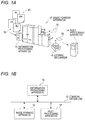
- FIG. 1B is a block diagram showing an example configuration of a 3D modeling system according to a first exemplary embodiment of the present invention
- FIG. 2 is a schematic diagram showing the example configuration of the 3D modeling system according to the first exemplary embodiment
- FIG. 3A is a schematic diagram illustrating slice image data used in sheet lamination 3D modeling
- FIG. 3B is a schematic diagram illustrating an image forming process and a post-processing process of the sheet lamination 3D modeling
- FIGS. 4A, 4B and 4C are schematic diagrams showing a slice image formed on a recording medium
- FIGS. 5A and 5B are schematic diagrams illustrating examples of control data that specify a cutting line
- FIGS. 6A and 6B are schematic diagrams illustrating examples of control data that specify a glue application region
- FIG. 7 is a block diagram showing an example electrical configuration of an information processing apparatus according to the exemplary embodiment.
- FIG. 8 is a block diagram showing an example functional configuration of the information processing apparatus according to the exemplary embodiment.
- FIG. 9 is a flowchart showing a processing procedure of a case that no interrupt process is accepted.
- FIG. 10 is a flowchart showing an example processing procedure of an information processing program according to the first exemplary embodiment of the invention.
- FIG. 11 is a sequence diagram illustrating a main operation of the 3D modeling system according to the first exemplary embodiment
- FIG. 12 is a flowchart showing an example processing procedure of an information processing program according to a second exemplary embodiment of the invention.
- FIG. 13 is a flowchart showing an example processing procedure of the interrupt judgment process
- FIG. 14 is a sequence diagram illustrating an operation that the 3D modeling system performs after a judgment that an interrupt condition is not satisfied is made in the interrupt judgment process;
- FIG. 15 is a flowchart showing an example processing procedure of an information processing program according to a third exemplary embodiment of the invention.
- FIG. 16 is a flowchart showing a processing procedure of a preferential interrupt judgment process
- FIG. 17 is a sequence diagram illustrating an operation that the 3D modeling system performs after a judgment that a preferential interrupt condition is not satisfied is made in the preferential interrupt judgment process.
- FIGS. 18A and 18B are diagrams illustrating how individual apparatus constituting an in-line 3D modeling system are arranged.
- the 3D modeling system manufactures a three-dimensional (3D) modeled object by a sheet lamination 3D modeling method.
- the sheet lamination 3D modeling method plural pieces of slice data are generated by slicing three-dimensional (3D) data of a 3D model by plural planes and slice images are formed on respective sheet-like recording media such as paper sheets on the basis of the plural pieces of slice data.
- 3D modeling post-processing is performed on the recording media on which the slice images are formed; for example, the plural recording media are laminated by subjecting them to certain processing.
- pluralitural pieces of data relating to 3D data of one 3D model may be referred to as a “series of data”; for example, plural pieces of slice data as mentioned above may be referred to as a “series of slice data.”
- FIG. 1B is a block diagram showing an example configuration of a 3D modeling system according to the exemplary embodiment.
- FIG. 2 is a schematic diagram showing the example configuration of the 3D modeling system according to the exemplary embodiment.
- the 3D modeling system according to the exemplary embodiment is equipped with an information processing apparatus 10 , an image forming apparatus 12 , and a 3D modeling post-processing apparatus 14 .
- the 3D modeling system is an in-line system in which the 3D modeling apparatus 14 is incorporated as one of post-processing apparatus. As shown in FIG. 2 , the 3D modeling apparatus 14 is disposed close to the image forming apparatus 12 and shares a recording medium conveyance path with the image forming apparatus 12 . Thus, recording media 50 on which slice images have been formed by the image forming apparatus 12 are supplied to the 3D modeling post-processing apparatus 14 without delay and subjected to post-processing there.
- the image forming apparatus 12 forms images on respective recording media 50 on the basis of raster image data.
- the raster image data are an example of the “image formation data”.
- the image forming apparatus 12 is not dedicated to 3D modeling; it functions as an ordinary image forming apparatus if instructed to work for image formation based on 2D image data.
- the information processing apparatus 10 performs different kinds of information processing depending on whether it is instructed to work for image formation based on 2D image data or 3D modeling based on 3D data.
- the image forming apparatus 12 is an apparatus for forming an image on a recording medium by electrophotography, for example.
- the image forming apparatus 12 includes a photoreceptor drum, a charging device, an exposing device, a developing device, a transfer device, a fusing device, etc.
- the charging device charges the photoreceptor drum.
- the exposing device exposes the charged surface of the photoreceptor drum to light that reflects an image to be formed.
- the developing device develops, with toner, an electrostatic latent image formed on the photoreceptor drum by the exposure.
- the transfer device transfers a toner image formed on the photoreceptor drum by exposure to a recording medium.
- the fusing device fuses the toner image transferred to the recording medium.
- the image forming apparatus 12 may be an inkjet recording apparatus, in which case the image forming apparatus 12 includes an inkjet recording head for ejecting ink droplets toward a recording medium according to an image to be formed and other components.
- the information processing apparatus 10 If instructed to work for 3D modeling based on 3D data, the information processing apparatus 10 generates slice data of plural pages on the basis of the 3D data and stores the generated slice data of plural pages in a memory such as a RAM.
- the information processing apparatus 10 of the in-line 3D modeling system reads out the slice data of plural pages page by page.
- the information processing apparatus 10 generates raster image data of one page on the basis of read-out slice data of each page, and outputs the raster image data of one page to the image forming apparatus 12 .
- the information processing apparatus 10 If instructed to work for image formation based on 2D image data, the information processing apparatus 10 generates raster image data of 2D images from the 2D image data and outputs the generated raster image data to the image forming apparatus 12 .
- the information processing apparatus 10 of the in-line 3D modeling system further generates control data of one page on the basis of read-out slice data of each page.
- the control data are data for allowing the 3D modeling post-processing apparatus 14 to perform 3D modeling post-processing.
- control data include control data that specify a cutting line along which to cut out a lamination component from a recording medium and control data that specify a glue application region where glue is applied to the recording medium.
- Raster image data of one page and control data of one page corresponding to the same slice image are generated on the basis of the same slice data.
- the information processing apparatus 10 outputs the generated control data of one page to the 3D modeling post-processing apparatus 14 .
- each recording medium 50 on which a slice image has been formed by the image forming apparatus 12 is supplied uninterruptedly to the 3D modeling post-processing apparatus 14 .
- the 3D modeling post-processing apparatus 14 performs 3D modeling post-processing on the supplied recording medium 50 according to control data corresponding to the slice image formed on the recording medium 50 .
- FIGS. 18A and 18B are diagrams illustrating examples of how the individual apparatus constituting the in-line 3D modeling system are arranged in a case that the in-line 3D modeling system includes a post-processing apparatus 17 in addition to the 3D modeling post-processing apparatus 14 .
- the image forming apparatus 12 , the other post-processing apparatus 17 , and the 3D modeling post-processing apparatus 14 may be arranged in the feeding direction of a recording medium 50 in this order, that, is, the order shown in FIG. 18A .
- each recording medium 50 on which a slice image has been formed by the image forming apparatus 12 is supplied to the 3D modeling post-processing apparatus 14 past the other post-processing apparatus 17 .
- the image forming apparatus 12 , the 3D modeling post-processing apparatus 14 , and the other post-processing apparatus 17 may be arranged in the feeding direction of a recording medium 50 in this order, that is, the order shown in FIG. 18B .
- each recording medium 50 on which a 2D image has been formed by the image forming apparatus 12 is supplied to the other post-processing apparatus 17 past the 3D modeling post-processing apparatus 14 .
- the in-line 3D modeling system will be described with an assumption that it is not equipped with the other post-processing apparatus 17 and the 3D modeling post-processing apparatus 14 will be abbreviated as a “post-processing apparatus 14 .”
- FIG. 1A shows, as a referential example, a configuration in which the image forming apparatus 12 and the 3D modeling post-processing apparatus 14 are spaced from each other and does not share a conveyance path of recording media 50 (offline or near-line). Since the image forming apparatus 12 and the 3D modeling post-processing apparatus 14 does not share a conveyance path, plural recording media 50 on which a series of slice images are formed are stacked in order of formation of the slice images and stored in a storing mechanism 16 such as a stacker. A bundle of stacked recording media 50 is taken out of the storing mechanism 16 and supplied to the 3D modeling post-processing apparatus 14 together.
- FIG. 3A is a schematic diagram illustrating slice image data used in sheet lamination 3D modeling
- FIG. 3B is a schematic diagram illustrating an image forming process and a post-processing process of the sheet lamination 3D modeling.
- the information processing apparatus 10 generates plural pieces of slice data by slicing 3D data of a 3D model M by plural respective slicing planes.
- the plural slicing planes are indicated by broken lines.
- the slice data represent sectional images (slice images) obtained by slicing the 3D model M by the slicing planes.
- One slice image is formed on each recording medium 50 .
- slice data of plural pages are generated as a series of slice data.
- slice data of each page are converted into raster image data.
- slice data of T (first to Tth) pages are generated by slicing 3D data by T (first to Tth) slicing planes.
- T slice images Mn are converted into raster image data of T pages.
- the image forming apparatus 12 and the post-processing apparatus 14 share a conveyance path 26 .
- the post-processing apparatus 14 is equipped with a glue applying unit 20 which performs a glue applying operation, a cutting-out unit 22 which performs a cutting-out operation, and a compression bonding unit 24 which performs a compression bonding operation.
- the glue applying unit 20 , the cutting-out unit 22 , and the compression bonding unit 24 are arranged in this order along the conveyance path 26 for feeding recording media 50 .
- the image forming apparatus 12 acquires raster image data page by page, and forms a slice image on a recording medium 50 on the basis of raster image data of one page.
- the recording medium 50 on which the slice image has been formed is supplied to the post-processing apparatus 14 .
- the post-processing apparatus 14 acquires control data of one page that correspond to the raster image data.
- the post-processing apparatus 14 performs post-processing on the received recording medium 50 uninterruptedly according to the acquired control data of one page.
- the image forming apparatus 12 acquires T (first to Tth) raster image data page by page in order from the first page and forms a slice image Mn on each recording medium 50 on the basis of acquired raster data of one page.
- An nth slice image Mn is formed on an nth recording medium 50 n , n is a number that is one of “1” to “T.”
- T recording media 50 1 - 50 T on which T respective slice images M 1 -M T are formed are laminated in the post-processing process in order of formation of the slice images M 1 -M T , that is, in ascending order of the numbers (from to “1” to “T”).
- FIGS. 4A, 4B and 4C are schematic diagrams showing an example slice image formed on a recording medium 50 .
- a slice image formed on a recording medium 50 consists of a lamination component 52 to become part of a 3D modeled object when subjected to lamination and an unnecessary portion 53 .
- the lamination component 52 has a colored region 56 which is a peripheral region having a preset width.
- the outer circumferential line of the lamination component 52 is a cutting line 54 along which to cut out the lamination component 52 from the recording medium 50 .
- a glue application region 58 is set inside the outer circumferential line (cutting line 54 ) of the lamination component 52 ; for example, the glue application region 58 is the region located inside and adjoining the colored region 56 .
- glue may be applied to the entire surface of the recording medium 50 including the unnecessary portion 53
- setting the glue application region 58 as a region located inside the outer circumferential line of the lamination component 52 makes it easier to remove removal target portions D (see FIG. 3B ) than in the case that glue is applied to the entire surface of the recording medium 50 .
- setting the glue application region 58 as a region located inside the outer circumferential line of the lamination component 52 prevents an event that glue sticks out of the lamination component 52 in a compression bonding operation that is performed after glue application.
- a width of the colored region 56 and a retreat width of the glue application region 58 from the outer circumferential line of the lamination component 52 may be set when a user inputs instructions about 3D modeling by, for example, displaying a setting picture on a display 34 of the information processing apparatus 10 and receiving settings from the user through an operation unit 32 .
- preset initial settings may be employed.
- Control data include control data that specify the cutting line 54 and control data that specify the glue application region 58 .
- the control data that specify the cutting line 54 are coordinate data of points located on a route of the cutting line 54 .
- the control data that specify the glue application region 58 are coordinate data of points existing in the glue application region 58 .
- the recording media 50 on which the slice images are formed are supplied one by one from the image forming apparatus 12 to the glue applying unit 20 .
- the glue applying unit 20 applies glue to the glue application region 58 of each recording medium 50 according to control data that specify the glue application region 58 .
- the glue applying unit 20 may be equipped with a glue ejection head for ejecting glue, which is moved in a lamination direction (Z direction) and directions parallel with the plane of the recording medium 50 (X and Y directions). Glue is applied to the glue application region 58 of the recording medium 50 as the glue ejection head scans the glue application region 58 while ejecting glue.
- the recording medium 50 is supplied to the cutting-out unit 22 .
- the cutting-out unit 22 forms a cut in each recording medium 50 along the cutting line 54 according to control data that specify the cutting line 54 .
- the cutting-out unit 22 may be a cutter having a blade. The blade of the cutter is moved in the lamination direction (Z direction) and the directions parallel with the plane of the recording medium 50 (X and Y directions). A cut is formed in the recording medium 50 by moving the blade of the cutter in the X and Y directions while pressing it against the recording medium 50 .
- a cutting depth is determined by adjusting the position of the blade of the cutter in the lamination direction.
- the cutting depth may be such that the cut does not reach the back surface of each recording medium 50 , in which case the lamination component 52 is not separated from the recording medium 50 and hence can be prevented from being lost in the process of conveyance of the recording medium 50 .
- the cutter have a function of forming a cut along the cutting line 54 of a recording medium 50 , and the cutter is not limited to a mechanical cutter that presses a blade against a recording medium 50 .
- the cutter may be an ultrasonic cutter that forms a cut by applying ultrasonic waves to a recording medium 50 or a laser cutter that forms a cut by irradiating a recording medium 50 with laser light.
- the cutting-out unit 22 may form plural perforations in a recording medium 50 along the cutting line 54 . Where plural perforations are formed, the lamination component 52 is kept connected to the recording medium 50 and hence can be prevented from being lost in the process of conveyance of the recording medium 50 even more reliably.
- Each recording medium 50 that has been subjected to the cutting operation is supplied to the compression bonding unit 24 .
- the compression bonding unit 24 stacks received recording media 50 successively.
- the plural recording media 50 1 to 50 T are stacked in order that the number representing each of them ascends from to “1” to “T.”
- the compression bonding unit 24 compression-bonds the bundle of stacked plural recording media 50 together by pressing it in the lamination direction.
- each of the plural glue-applied recording media 50 1 to 50 T is bonded to the recording media 50 located immediately above and below in the glue application regions 58 .
- the recording media 50 that have been subjected to the cutting-out operation are composed of the lamination components 52 that constitute a 3D modeled object P as a result of the lamination and the unnecessary portions 53 .
- the unnecessary portions 53 are not removed and remain parts of the recording media 50 .
- the unnecessary portions 53 serve as a support member for supporting the 3D modeled object P that is a laminate of the lamination components 52 .
- removal target portions D are separated from the laminate of the lamination components 52 of the recording media 50 , whereby the 3D modeled object P are separated.
- FIGS. 5A and 5B are schematic diagrams illustrating examples of control data that specify a cutting line 54 .
- FIGS. 6A and 6B are schematic diagrams illustrating examples of control data that specify a glue application region 58 .
- slice data include coordinate data of apices of intersection regions where polygons intersect a slicing plane. The intersection regions exist along the outer circumferential line of a lamination component 52 .
- coordinate data of respective points located on the route of a cutting line 54 such as coordinates (x 0 , y 0 ) of point A 0 , are made control data that specify the cutting line 54 .
- a star-shaped lamination component 52 has twelve apices A 0 to A 11 .
- the cutting line 54 is specified by tracing the points A 0 to A 11 in order of A 0 ⁇ A 2 ⁇ A 3 ⁇ A 4 ⁇ A 5 ⁇ A 6 ⁇ A 7 ⁇ A 8 ⁇ A 9 ⁇ A 10 ⁇ A 11 .
- coordinate data of respective perforations located on the route of a cutting line 54 are made control data that specify the cutting line 54 .
- the cutting line 54 is specified by tracing points of the perforations in order of their formation (e.g., A 0 ⁇ A 2 ⁇ A 3 ⁇ A 4 . . . ).
- coordinate data of respective points of a glue application region 58 are made control data that specify the glue application region 58 .
- the glue application region 58 is one size smaller than the lamination component 52 and is set inside the outer circumferential line of the lamination component 52 .
- a glue application region 58 may be specified by reducing the image of the lamination component 52 .
- the glue application region 58 is disposed so that its canter of gravity coincides with that of the image of the lamination component 52 .
- Coordinate data of respective points of the glue application region 58 are determined on the basis of its retreat width from the outer circumferential line of the lamination component 52 and coordinate data of points located on the route of the cutting line 54 .
- Glue may be applied in selected portions of the glue application region 53 .
- the glue density need not be constant over the entire glue application region 58 . Where the glue density is set variable, the glue density may be set higher in a peripheral region of the glue application region 58 than in its central region.
- the origin of control data that specify a cutting line 54 and the origin of control data that specify a glue application region 58 are set the same as the origin of slice image formation.
- the post-processing apparatus 14 has an image reading function, a procedure may be employed that the image forming apparatus 12 forms a mark image indicating the origin of control data on a recording medium 50 together with a slice image and the post-processing apparatus 14 acquires position information indicating the origin of control data by reading the mark image.
- control data is not limited to coordinate data.
- control data may be image data in which a cutting line 54 , a glue application region 58 , etc. are represented by figures or images, such as binary raster image data.
- binary raster image data in the example shown in FIG. 4B , the pixel values of the cutting line 54 are made “1” and those of the other regions are made “0.”
- FIG. 4B the example shown in FIG. 4B
- the pixel values of the glue application region 58 are made “1” and those of the other regions are made “0.”
- the glue election head of the glue applying unit 20 ejects glue toward a recording medium 50 when the pixel value is equal to “1” and does not eject glue toward the recording medium 50 when the pixel value is equal to “0.”
- FIG. 7 is a block diagram showing the electrical configuration of the information processing apparatus 10 according to the exemplary embodiment.
- the information processing apparatus 10 is equipped with an information processing unit 30 , an operation unit 32 for receiving a user manipulation, a display 34 for displaying information to a user, a communication unit 36 for communicating with an external apparatus 31 , and a memory 38 such as an external storage device.
- the operation unit 32 , the display 34 , the communication unit 36 , and the memory 38 are connected to an input/output interface (I/O) 30 E of the information processing unit 30 .
- I/O input/output interface
- the information processing unit 30 is equipped with a CPU (central processing unit) 30 A, a ROM (read-only memory) 30 B, a RAM (random access memory) 30 C, a nonvolatile memory 30 D, and the I/O 30 E.
- the CPU 30 A, the ROM 30 B, the RAM 30 C, the nonvolatile memory 30 D, and the I/O 30 E are connected to each other by a bus 30 F.
- the CPU 30 A reads out a program from the ROM 30 B and executes the program using the RAM 30 C as a working area.
- the operation unit 32 receives a user manipulation through a mouse, a keyboard, etc.
- the display 34 displays various pictures to a user using a display device.
- the communication unit 36 communicates with the external apparatus 31 through a wired or wireless communicate line.
- the communication unit 36 functions as an interface for communicating with the external apparatus 31 such as a computer that is connected to a network such as the Internet.
- the memory 38 is equipped with a storage device such as a hard disk drive.
- FIG. 8 is a block diagram showing the functional configuration of the information processing apparatus 10 according to the exemplary embodiment. As shown in FIG. 8 , the information processing apparatus 10 is equipped with a file format conversion unit 40 , a raster processing unit 42 , and a 3D data processing unit 44 .
- the file format conversion unit 40 converts the received PDL data into intermediate data.
- the raster processing unit 42 generates raster image data by rasterizing the intermediate data produced by the file format conversion unit 40 . Furthermore, the raster processing unit 42 generates raster image data by rasterizing slice image data generated by an image data generation unit 47 (described later).
- the 3D data processing unit 44 generates slice image data and control data by processing received 3D data. More specifically, the 3D data processing unit 44 is equipped with a slice processing unit 45 , a slice data memory 46 , the image data generation unit 47 , and a control data generation unit 48 .
- the slice processing unit 45 generates slice data of plural pages on the basis of received 3D data.
- the slice data memory 46 stores the slice data of plural pages generated by the slice processing unit 45 .
- the image data generation unit 47 reads out slice data of each page from the slice data memory 46 , and generates slice image data on the basis of the read-out slice data.
- the control data generation unit 48 reads out the same slice data as the image data generation unit 47 does and generates control data on the basis of the read-out slice data.
- the 2D image data are data that have been acquired as PDL data.
- the PDL data are converted by the file format conversion unit 40 into intermediate data, which are output to the raster processing unit 42 .
- the intermediate data are rasterized by the raster processing unit 42 into raster image data, of 2D images, which are output to the image forming apparatus 12 .
- the intermediate data are interval data produced by dividing each of objects (e.g., font characters, graphic figures, and image data) that are image elements of each page image into intervals of respective raster scanning lines.
- Each piece of interval data includes sets of coordinates of the two ends of the interval concerned and pieces of information indicating pixel values of respective pixels in the interval.
- the data transfer rate in the information processing apparatus 10 is increased because the PDL data are converted into the intermediate data and then the latter are transferred.
- 3D data of a 3D model M are acquired.
- the slice processing unit 45 generates slice data of plural pages on the basis of the 3D data, and stores the generated slice data of plural pages in the slice data memory 46 .
- the 3D data and the slice data will be described below in detail.
- the 3D data of the 3D model M are OBJ format 3D data (hereinafter referred to as “OBJ data”).
- OBJ data the 3D model M is expressed as a set of polygons (triangles).
- the 3D data may be of another format such as the STL format. Since STL format 3D data have no color information, color information is added when STL format 3D data are used.
- the OBJ data include an OBJ file relating to shape data and an MTL file relating to color information.
- OBJ file surface numbers specific to respective polygons (triangles), coordinate data of the apices of the polygons, etc. are defined so as to be correlated with the respective polygons.
- MTL file pieces of color information are defined so as to be correlated with the respective polygons.
- Planes that are parallel with a ground surface (XY plane) on which the 3D model M is placed are employed as slicing planes.
- a lowest layer of the 3D model M is set as a first slicing plane.
- Slice data are generated every time the slicing surface is shifted by a predetermined lamination pitch (distance) p in a lamination direction (Z-axis direction).
- the lowest slicing plane is given a number “1” and the slicing plane number is increased by “1” every time the slicing plane is shifted.
- the example shown in FIG. 3A has T slicing planes having numbers “1” to “T” (indicated by broken lines).
- Slice data represent sectional images (slice images) obtained by slicing the 3D model M by the slicing planes, respectively. More specifically, slice data of each page represents a sectional image (slice image) of the 3D model M in the form of a slicing plane number, coordinate data of the apices of intersection regions where polygons intersect the slicing plane, and pieces of color information that are set for the respective polygons that intersect the slicing plane.
- Slice data of T (first to Tth) pages are generated by the T respective slicing planes.
- the image data generation unit 47 generates slice image data of one page on the basis of slice data of each page that is read out from the slice data memory 46 .
- the slice data are converted into slice image data of a file format such as JPEG.
- colored regions may be added so as to be reflected in a corresponding slice image.
- the generated slice image data are output to the raster processing unit 42 .
- the raster processing unit 42 generates raster image data by rasterizing the slice image data generated by the image data generation unit 47 , and outputs the generated raster image data to the image forming apparatus 12 .
- the image data generation unit 47 may be configured so as to cause generation of intermediate data.
- the image data generation unit 47 generates PDL data of one page on the basis of slice data of each page that are read out from the slice data memory 46 , and outputs the generated PDL data of one page to the file format conversion unit 40 .
- the file format conversion unit 40 converts the PDL data into intermediate data, and outputs the intermediate data to the raster processing unit 42 .
- the raster processing unit 42 generates raster image data of a slice image by rasterizing the intermediate data, and outputs the generated raster image data to the image forming apparatus 12 .
- the control data generation unit 48 generates control data of one page on the basis of slice data of each page that are read out from the slice data memory 46 , and outputs the generated control data of one page to the post-processing apparatus 14 .
- the information processing apparatus 10 if instructed to work for image formation based on 2D image data during execution of a 3D data process, the information processing apparatus 10 suspends the 3D data process and starts a 2D data process as an interrupt process. That is, the information processing apparatus 10 accepts an interrupt process.
- FIG. 9 is a flowchart showing a processing procedure of a case that no interrupt process is accepted.
- step S 100 the CPU 30 A judges whether data relating to an instruction are 3D data. If 3D modeling based on 3D data is commanded, the CPU 30 A executes the process shown in step S 102 . If not, the CPU 30 A executes the process shown in step S 104 , that is, performs the above-described 2D data processing.
- step S 106 the CPU 30 A judges whether there is a next process to be executed. If receiving an instruction to perform 2D image formation or 3D modeling during execution of the 3D data processing or 2D data processing, the CPU 30 A executes the process shown in step S 100 (steps S 100 -S 106 are executed again) because there is a next process to be executed. If judging at step S 106 that there is no next process to be executed, the CPU 30 A finishes the routine.
- the processing speed (lamination rate) of the post-processing apparatus 14 is as very low as about several millimeters per hour.
- the processing speed of a process to manufacture of a 3D modeled object that is, the processing speed of a 3D data process, is limited by the processing speed of the post-processing apparatus 14 .
- the information processing apparatus 10 does not accept interruption of a 2D data process.
- the information processing apparatus 10 cannot execute a 2D data process during execution of the 3D data process. If the 3D modeling system is occupied by a 3D data process in this manner, image formation based on 2D image data can hardly be performed and the processing ability of the image forming apparatus 12 is lowered accordingly.
- FIG. 10 is a flowchart showing an example processing procedure of the information processing program according to the first exemplary embodiment of the invention.
- the information processing program is stored in the ROM 30 B of the information processing apparatus 10 .
- the information processing program is read out from, the ROM 30 B and executed by the CPU 30 A of the information processing apparatus 10 . Execution of the information processing program is started upon reception of an image formation instruction or a 3D modeling instruction from a user.
- the exemplary embodiment is directed to the case that the information processing program is stored in the ROM 30 B of the information processing apparatus 10 in advance, the invention is not limited to this case.
- the information processing program may be provided being stored in a computer-readable, portable storage medium such as a magneto-optical disc, a CD-ROM (compact disc-read only memory), or a USB memory or provided over a network.
- step S 200 the CPU 30 A judges whether data relating to an instruction is 3D data. If 3D modeling based on 3D data is commanded, the CPU 30 A executes the process shown in step S 202 , that is, starts execution of a 3D data process (details were described above). On the other hand, if image formation based on 2D image data is commanded, the CPU 30 A executes the process shown in step S 204 , that is, performs a 2D data process (details were described above). This routine is finished upon completion of the execution of the 2D data process.
- the CPU 30 A judges whether an interrupt request has been received during the execution of the 3D data process. If an instruction to perform 2D image formation has been received, the CPU 30 A executes the process shown in step S 208 . The CPU 30 A suspends the execution of the 3D data process at step S 208 and executes the 2D data process at step S 210 . At step S 212 , the CPU 30 A restarts the 3D data process whose execution has been suspended. On the other hand, it is judged at step S 206 that no interrupt request has been received, the CPU 30 A executes the process shown in step S 214 to execute the 3D data process without interruption.
- the CPU 30 A judges whether the 3D data process has been completed.
- the CPU 30 A makes this judgment during execution of the 3D data process irrespective of whether the 3D data process was restarted after suspension or has been executed continuously without interruption. If the 3D data process has not been completed yet, the CPU 30 A executes the process shown in step S 206 to judge again whether an interrupt request has been received during the execution of the 3D data process. On the other hand, this routine is finished if the 3D data process has been completed.
- FIG. 11 is a sequence diagram illustrating a main operation of the 3D modeling system according to the first exemplary embodiment.
- the information processing apparatus 10 upon receiving 3D data at steps S 300 , at step S 302 the information processing apparatus 10 generates slice data of plural pages on the basis of the received 3D data.
- the information processing apparatus 10 stores the slice data of plural pages generated at step S 304 .
- the information processing apparatus 10 reads out slice data of one page at step S 306 and generates slice image data of one page on the basis of the read-out slice data of one page.
- the information processing apparatus 10 generates raster image data of one page from the slice image data of one page and outputs the generated raster image data of one page to the image forming apparatus 12 .
- the image forming apparatus 12 acquires the raster image data of one page at step S 312 , and forms a slice image on a recording medium 50 on the basis of the acquired raster image data of one page at step S 314 .
- the recording medium 50 on which the slice image has been formed is supplied to the post-processing apparatus 14 .
- the information processing apparatus 10 reads out the same control data as it did at step S 306 , generates control data of one page on the basis of the read-out slice data of one page, and outputs the generated control data of one page to the post-processing apparatus 14 .
- the control data of one page are data for allowing the post-processing apparatus 14 to perform post-processing on the recording medium 50 on which the slice image has been formed by the image forming apparatus 12 on the basis of the received raster image data of one page.
- the post-processing apparatus 14 acquires the control data of one page at step S 318 , and performs post-processing on the recording medium 50 on which the slice images has been formed, according to the control data at step S 320 .
- Steps S 306 -S 320 are executed repeatedly for each piece of slice data of one page, whereby a slice image is formed on a recording medium 50 by the image forming apparatus 12 for each piece of slice data of one page and post-processing is performed by the post-processing apparatus 14 on the recording medium 50 on which the slice image has been formed.
- This process which is executed repeatedly page by page is referred to as a “page-by-page process.”
- raster image data and control data are output at a rate that is suitable for a processing speed of the post-processing apparatus 14 .
- the information processing apparatus 10 accepts the interrupt request.
- the information processing apparatus 10 acquires 2D image data.
- the information processing apparatus 10 suspends the page-by-page process at step S 324 , and executes a 2D data process at step S 326 .
- the 2D image data are converted into raster image data, which are supplied to the image forming apparatus 12 .
- the image forming apparatus 12 acquires the raster image data for formation of 2D images at step S 328 , and forms 2D images on respective recording media 50 on the basis of the acquired raster image data at step S 330 .
- the recording media 50 on which the 2D images have been formed pass through the post-processing apparatus 14 and stored in a storing mechanism that is disposed at a downstream end of the system.
- the information processing apparatus 10 restarts the page-by-page process that has been suspended.
- image formation based on 2D image data, formation of remaining slice images, and a remaining part of the post-processing of the 3D modeling process are executed in the above-described order.
- a 2D data process is executed by interrupting a 3D data process (page-by-page process) and the 3D data process is restarted after completion of the 2D data process. Since the image formation based on the 2D image data is executed preferentially over the other processes, the processing ability of the image forming apparatus 12 is not lowered. Formation of remaining slice images and a remaining part of the post-processing of the 3D modeling process are performed together.
- FIG. 12 is a flowchart showing an example processing procedure of an information processing program according to the second exemplary embodiment of the invention. Steps of the information processing program according to the second exemplary embodiment having the same steps in the information processing program according to the first exemplary embodiment (see FIG. 10 ) will be given the same reference symbols as the latter and described in simplified manners.
- the CPU 30 A judges at step S 206 whether an interrupt request has been received during the execution of the 3D data process. If an interrupt request has been received, at step S 208 the CPU 30 A suspends the execution of the 3D data process. On the other hand, if judging at step S 206 that no interrupt request has been received, the CPU 30 A executes the process shown in steps S 214 to execute the 3D data process without interruption.
- FIG. 13 is a flowchart showing a processing procedure of the interrupt judgment process.
- the CPU 30 A acquires information indicating a remaining time Tr of the 3D data process at step S 500 and acquires information indicating a time Tn to be taken by a 2D data process at step S 502 .
- the CPU 30 A judges whether the time Tn is shorter than or equal to the remaining time Tr. If Tn ⁇ Tr, the CPU 30 A judges at step S 506 that the interrupt condition is satisfied and finishes this routine. If Tn>Tr, the CPU 30 A judges at step S 508 that the interrupt condition is not satisfied and finishes this routine.
- step S 402 the CPU 30 A judges whether the interrupt condition is satisfied on the basis of the result of the interrupt judgment process. If the interrupt condition is satisfied, the CPU 30 A executes the process shown in step S 210 (2D data process). At step S 212 , the CPU 30 A restarts the 3D data process that has been suspended. On the other hand, if the interrupt condition is not satisfied, the CPU 30 A goes to step S 212 skipping step S 210 to restart the 3D data process that has been suspended.
- step S 216 the CPU 30 A judges whether the 3D data process has been completed. If the 3D data process has not been completed yet, the CPU 30 A executes the process shown in step S 206 to judge again whether an interrupt request has been received during the execution of the 3D data process. On the other hand, if the 3D data process has been completed, the CPU 30 A executes the 2D process that does not satisfy the interrupt condition at step S 404 and finishes this routine.
- FIG. 14 is a sequence diagram illustrating an operation that the 3D modeling system performs after a judgment that the interrupt, condition is not satisfied is made in an interrupt judgment process.
- the information processing apparatus 10 executes the interrupt judgment process after suspending a page-by-page process at step S 324 . However, if the interrupt condition is not satisfied, the information processing apparatus 10 does not execute an interrupt process and restarts a 3D data process at step S 340 .
- step S 342 i.e., after completion of the 3D data process
- the information processing apparatus 10 executes the 2D data process that was judged not to satisfy the interrupt condition.
- Two-dimensional image data are converted into raster image data, which are output to the image forming apparatus 12 .
- the image forming apparatus 12 acquires the raster image data for formation of 2D images at step S 344 and forms 2D images on respective recording media 50 on the basis of the raster image data at step S 346 .
- the recording media 50 on which the 2D images have been formed pass through the post-processing apparatus 14 and stored in a storing mechanism which is disposed at a downstream end of the system.
- a 3D data process is interrupted in the midst of its execution and a 2D data process is started if a time Tn to be taken by the 2D data process is shorter than or equal to a remaining time Tr of the 3D data process.
- a 2D data process will be executed later if the time Tn is longer than the remaining time Tr.
- the processing ability of the image forming apparatus 12 is not lowered.
- the delay of 3D modeling is made shorter than in a case that an interrupt 2D data process is always executed upon its occurrence.
- formation of remaining slice images and a remaining part of post-processing of a 3D modeling process are performed together. That is, a page-by-page process of the 3D data process is restarted upon completion of an interrupt 2D data process.
- a third exemplary embodiment is the same as the first exemplary embodiment except that in the former an interrupt process is accepted with an exception that formation of remaining slice images of 3D modeling is performed first if a predetermined condition is satisfied, and hence only difference from the first exemplary embodiment will be described.
- FIG. 15 is a flowchart showing an example processing procedure of an information processing program according to the third exemplary embodiment of the invention. Steps of the information processing program according to the third exemplary embodiment having the same steps in the information processing program according to the first exemplary embodiment (see FIG. 10 ) will be given the same reference symbols as the latter and described in simplified manners.
- the CPU 30 A judges at step S 206 whether an interrupt request has been received during the execution of the 3D data process. If an interrupt request has been received, at step S 208 the CPU 30 A suspends the execution of the 3D data process. On the other hand, if judging at step S 206 that no interrupt request has been received, the CPU 30 A executes the process shown in step S 214 to execute the 3D data process without interruption.
- FIG. 16 is a flowchart showing a processing procedure of the preferential interrupt judgment process. As shown in FIG. 16 , the CPU 30 A acquires the number Pr of remaining images to be formed of the 3D data process at step S 700 and acquires the number Pn of images to be formed of the 2D data process at step S 702 .
- the CPU 30 A judges whether the number Pn is larger than the number Pr. If Pn>Pr, the CPU 30 A judges at step S 706 that the preferential interrupt condition is satisfied and finishes this routine. If Pn Pr, the CPU 30 A judges at step S 708 that the preferential interrupt condition is satisfied and finishes this routine.
- step S 602 the CPU 30 A judges whether the preferential interrupt condition is satisfied on the basis of the result of the preferential interrupt judgment process. If the preferential interrupt condition is satisfied, the CPU 30 A executes the process shown in step S 210 (2D data process). At step S 212 , the CPU 30 A restarts the 3D data process that has been suspended.
- step S 604 stacking process
- the CPU 30 A executes a 2D data process at step S 606 and restarts, at step S 608 , the 3D data process that has been suspended.
- the CPU 30 A reads out all of remaining slice data, generates slice image data, converts the generated slice image data into raster image data, and outputs the raster image data to the image forming apparatus 12 .
- the raster image data that are necessary for formation of remaining slice images for the 3D modeling are output to the image forming apparatus 12 together.
- the plural pieces of raster image data for formation of remaining slice images are output to the image forming apparatus 12 in such a manner that their order is reversed so that a recording medium 50 to be subjected to post-processing later is output earlier.
- step S 216 the CPU 30 A judges whether the 3D data process has been completed. If the 3D data process has not been completed yet, the CPU 30 A executes the process shown in step S 206 to judge again whether an interrupt request has been received during the execution of the 3D data process. On the other hand, this routine is finished if the 3D data process has been completed.
- FIG. 17 is a sequence diagram illustrating an operation that the 3D modeling system performs after a judgment that the preferential interrupt condition is not satisfied is made in a preferential interrupt judgment process.
- the information processing apparatus 10 executes the preferential interrupt judgment process after suspending a page-by-page process at step S 324 . If the preferential interrupt condition is not satisfied, the information processing apparatus 10 executes a stacking process which will be described below.
- the information processing apparatus 10 reads out slice data of all of remaining pages at step S 350 , and generates slice image data of the remaining pages on the basis of the slice data of the remaining pages at step S 352 .
- the information processing apparatus 10 generates raster image data of the remaining pages, and outputs the generated raster image data to the image forming apparatus 12 .
- the image forming apparatus 12 acquires the raster image data of the remaining pages at step S 356 , and forms slice images of the remaining pages on respective recording media 50 on the basis of the raster image data of the remaining pages at step S 358 .
- the recording media 50 on which the slice images of the remaining pages have been formed are stacked (i.e., stored together) in a storing mechanism which is disposed at a downstream end of the system.
- the bundle of recording media 50 stored in the storing mechanism is set in the post-processing apparatus 14 before a restart of the 3D data process.
- step S 360 the information processing apparatus 10 executes a 2D data process. Two-dimensional data are converted into raster image data, which are output to the image forming apparatus 12 .
- the image forming apparatus 12 acquires the raster image data for formation of 2D images at step S 362 , and forms 2D images on respective recording media 50 on the basis of the raster image data at step S 364 . Since the recording media 50 on which the 2D images have been formed need not be subjected to 3D modeling post-processing, they pass through the post-processing apparatus 14 and stored in the storing mechanism disposed at the downstream end of the system. The information processing apparatus 10 then restarts the page-by-page process that was suspended at step S 324 .
- the information processing apparatus 10 reads out slice data of one page from the slice data of the remaining pages, generates control data of one page from the slice data of one page, and outputs the control data of one page to the post-processing apparatus 14 .
- the post-processing apparatus 14 acquires the control data of one page at step S 368 , and performs post-processing on a corresponding, slice-image-formed recording medium 50 according to the control data at step S 370 .
- Steps S 366 -S 370 are executed repeatedly for slice data of each page.
- the raster image data for slice images of the remaining pages have already been generated and output, only control data are generated and output after the restart of the page-by-page process.
- a 3D data process is interrupted in the midst of its execution and a 2D data process is started irrespective of whether the preferential interrupt condition is satisfied or not.
- the processing ability of the image forming apparatus 12 is not lowered.
- a stacking process is executed to generate and output raster image data for formation of slice images of remaining pages, whereby slice images of the remaining pages of 3D modeling are formed before execution of a 2D data process.
- Post-processing on slice-image-formed recording media 50 of the remaining pages of the 3D modeling is performed later separately from the formation of the slice images of the remaining pages of the 3D modeling.
- the image forming apparatus 12 can perform another image forming process without waiting for execution of post-processing on the slice-image-formed recording media 50 of the remaining pages. During that course, the image forming apparatus 12 can be used as an ordinary image forming apparatus for forming images on the basis of 2D image data rather than an apparatus dedicated to 3D modeling. Furthermore, since the slice images of the remaining pages have already been formed by the image forming apparatus 12 , the post-processing apparatus 14 can start post-processing on the slice-image-formed recording media 50 of the remaining pages without any standby time.
- the interrupt judgment process of the second exemplary embodiment may be executed before the preferential interrupt judgment process of the third exemplary embodiment.
- a 2D data process is executed as an interrupt process only if a time Tn to be taken by the 2D data process is shorter than or equal to a remaining time Tr of a 3D data process.
- a stacking process is executed to form slice images of the remaining pages before execution of the 2D data process.
Landscapes
- Engineering & Computer Science (AREA)
- Physics & Mathematics (AREA)
- Chemical & Material Sciences (AREA)
- Materials Engineering (AREA)
- Manufacturing & Machinery (AREA)
- General Physics & Mathematics (AREA)
- Optics & Photonics (AREA)
- Mechanical Engineering (AREA)
- Computer Graphics (AREA)
- Geometry (AREA)
- Software Systems (AREA)
- Theoretical Computer Science (AREA)
- Accessory Devices And Overall Control Thereof (AREA)
Abstract
Description
- 10: Information processing apparatus
- 12: Image forming apparatus
- 14: 3D modeling post-processing apparatus (post-processing apparatus)
- 16: Storing mechanism
- 17: Post-processing apparatus
- 20: Glue applying unit
- 22: Cutting-out unit
- 24: Compression bonding unit
- 26: Conveyance path
- 30: Information processing unit
- 31: External apparatus
- 32: Operation unit
- 34: Display
- 36: Communication unit
- 38: Memory
- 40: File format, conversion unit
- 42: Raster processing unit
- 44: 3D data processing unit
- 45: Slice processing unit
- 46: Slice data memory
- 47: Image data generation unit
- 48: Control data generation unit
- 50: Recording medium
- 52: Lamination component
- 53: Unnecessary portion
- 54: Cutting line
- 56: Colored region
- 58: Glue application region
- M: 3D model
- Mn: Slice image
- P: 3D modeled object
- D: Removal target
Claims (8)
Applications Claiming Priority (2)
| Application Number | Priority Date | Filing Date | Title |
|---|---|---|---|
| JP2017-007076 | 2017-01-18 | ||
| JP2017007076A JP6834511B2 (en) | 2017-01-18 | 2017-01-18 | Information processing equipment, 3D modeling system, and programs |
Publications (2)
| Publication Number | Publication Date |
|---|---|
| US20180204374A1 US20180204374A1 (en) | 2018-07-19 |
| US10636202B2 true US10636202B2 (en) | 2020-04-28 |
Family
ID=62841566
Family Applications (1)
| Application Number | Title | Priority Date | Filing Date |
|---|---|---|---|
| US15/726,773 Active 2038-04-13 US10636202B2 (en) | 2017-01-18 | 2017-10-06 | Information processing apparatus for interrupting three-dimensional modeling, three-dimensional modeling system, and computer readable medium storing information processing program for the same |
Country Status (2)
| Country | Link |
|---|---|
| US (1) | US10636202B2 (en) |
| JP (1) | JP6834511B2 (en) |
Families Citing this family (1)
| Publication number | Priority date | Publication date | Assignee | Title |
|---|---|---|---|---|
| JP7077631B2 (en) * | 2018-01-18 | 2022-05-31 | コニカミノルタ株式会社 | Image inspection equipment and image formation system |
Citations (6)
| Publication number | Priority date | Publication date | Assignee | Title |
|---|---|---|---|---|
| US5774356A (en) * | 1994-05-25 | 1998-06-30 | Fuji Xerox Co., Ltd. | Image forming apparatus with job priority management of output processing |
| JP2000043149A (en) | 1998-07-30 | 2000-02-15 | Japan Steel Works Ltd:The | Three-dimensional modeling method and modeling apparatus |
| JP2000177016A (en) | 1998-12-17 | 2000-06-27 | Minolta Co Ltd | Manufacturing method of three-dimensional object |
| US6506477B1 (en) | 1998-12-17 | 2003-01-14 | Minolta Co., Ltd. | Apparatus and method for forming three-dimensional object |
| US20050270573A1 (en) * | 2003-12-23 | 2005-12-08 | Ferlitsch Andrew R | Systems and methods for adding post-collation operations and interleaved imaging jobs to an imaging job |
| US20160009069A1 (en) * | 2014-07-10 | 2016-01-14 | Microjet Technology Co., Ltd. | Rapid printing apparatus and method |
-
2017
- 2017-01-18 JP JP2017007076A patent/JP6834511B2/en active Active
- 2017-10-06 US US15/726,773 patent/US10636202B2/en active Active
Patent Citations (6)
| Publication number | Priority date | Publication date | Assignee | Title |
|---|---|---|---|---|
| US5774356A (en) * | 1994-05-25 | 1998-06-30 | Fuji Xerox Co., Ltd. | Image forming apparatus with job priority management of output processing |
| JP2000043149A (en) | 1998-07-30 | 2000-02-15 | Japan Steel Works Ltd:The | Three-dimensional modeling method and modeling apparatus |
| JP2000177016A (en) | 1998-12-17 | 2000-06-27 | Minolta Co Ltd | Manufacturing method of three-dimensional object |
| US6506477B1 (en) | 1998-12-17 | 2003-01-14 | Minolta Co., Ltd. | Apparatus and method for forming three-dimensional object |
| US20050270573A1 (en) * | 2003-12-23 | 2005-12-08 | Ferlitsch Andrew R | Systems and methods for adding post-collation operations and interleaved imaging jobs to an imaging job |
| US20160009069A1 (en) * | 2014-07-10 | 2016-01-14 | Microjet Technology Co., Ltd. | Rapid printing apparatus and method |
Non-Patent Citations (1)
| Title |
|---|
| Abstract and machine translation of JP 2000-43149. |
Also Published As
| Publication number | Publication date |
|---|---|
| JP2018116506A (en) | 2018-07-26 |
| US20180204374A1 (en) | 2018-07-19 |
| JP6834511B2 (en) | 2021-02-24 |
Similar Documents
| Publication | Publication Date | Title |
|---|---|---|
| US20180200943A1 (en) | Information processing apparatus, three-dimensional modeling system, and computer readable medium storing information processing program | |
| US10710300B2 (en) | Information processing apparatus, three-dimensional modeling system, and computer readable medium storing information processing program | |
| US10950028B2 (en) | Information processing apparatus, three-dimensional modeling system, and computer readable medium storing information processing program | |
| US10766198B2 (en) | Information processing apparatus for detecting expected trouble, three-dimensional modeling system, and computer readable medium storing information processing program for the same | |
| JP6958140B2 (en) | Information processing equipment, programs and 3D modeling systems | |
| US10636202B2 (en) | Information processing apparatus for interrupting three-dimensional modeling, three-dimensional modeling system, and computer readable medium storing information processing program for the same | |
| US11300944B2 (en) | Information processing apparatus, computer readable medium storing information processing program, and three-dimensional modeling system | |
| US11249706B2 (en) | Information processing apparatus, computer readable medium storing information processing program, and three-dimensional modeling system | |
| US20180204099A1 (en) | Information processing apparatus, three-dimensional modeling system, and computer readable medium storing information processing program | |
| US11325311B2 (en) | Information processing apparatus, non-transitory computer readable medium, and three-dimensional object forming system | |
| US10507615B2 (en) | Information processing apparatus, computer readable medium storing information processing program, and three-dimensional modeling system | |
| JP6880762B2 (en) | Information processing equipment, information processing programs and 3D modeling systems | |
| JP2018114684A (en) | Information processing device, three-dimensional molding system, and program | |
| JP2018114677A (en) | Information processing device, three-dimensional molding system, and program | |
| JP2019046222A (en) | Information processing apparatus, program and three-dimensional modeling system |
Legal Events
| Date | Code | Title | Description |
|---|---|---|---|
| FEPP | Fee payment procedure |
Free format text: ENTITY STATUS SET TO UNDISCOUNTED (ORIGINAL EVENT CODE: BIG.); ENTITY STATUS OF PATENT OWNER: LARGE ENTITY |
|
| AS | Assignment |
Owner name: FUJI XEROX CO., LTD., JAPAN Free format text: ASSIGNMENT OF ASSIGNORS INTEREST;ASSIGNORS:ISOBE, KIMIHIKO;MOCHIZUKI, MAMORU;HOTOKEISHI, KENICHIROU;AND OTHERS;REEL/FRAME:043835/0001 Effective date: 20171005 |
|
| STPP | Information on status: patent application and granting procedure in general |
Free format text: DOCKETED NEW CASE - READY FOR EXAMINATION |
|
| STPP | Information on status: patent application and granting procedure in general |
Free format text: NON FINAL ACTION MAILED |
|
| STPP | Information on status: patent application and granting procedure in general |
Free format text: FINAL REJECTION MAILED |
|
| STPP | Information on status: patent application and granting procedure in general |
Free format text: RESPONSE AFTER FINAL ACTION FORWARDED TO EXAMINER |
|
| STPP | Information on status: patent application and granting procedure in general |
Free format text: NOTICE OF ALLOWANCE MAILED -- APPLICATION RECEIVED IN OFFICE OF PUBLICATIONS |
|
| STCF | Information on status: patent grant |
Free format text: PATENTED CASE |
|
| AS | Assignment |
Owner name: FUJIFILM BUSINESS INNOVATION CORP., JAPAN Free format text: CHANGE OF NAME;ASSIGNOR:FUJI XEROX CO., LTD.;REEL/FRAME:058287/0056 Effective date: 20210401 |
|
| MAFP | Maintenance fee payment |
Free format text: PAYMENT OF MAINTENANCE FEE, 4TH YEAR, LARGE ENTITY (ORIGINAL EVENT CODE: M1551); ENTITY STATUS OF PATENT OWNER: LARGE ENTITY Year of fee payment: 4 |