US10636168B2 - Image processing apparatus, method, and program - Google Patents
Image processing apparatus, method, and program Download PDFInfo
- Publication number
- US10636168B2 US10636168B2 US15/575,199 US201615575199A US10636168B2 US 10636168 B2 US10636168 B2 US 10636168B2 US 201615575199 A US201615575199 A US 201615575199A US 10636168 B2 US10636168 B2 US 10636168B2
- Authority
- US
- United States
- Prior art keywords
- dimensional map
- pose
- feature point
- input image
- recognition target
- Prior art date
- Legal status (The legal status is an assumption and is not a legal conclusion. Google has not performed a legal analysis and makes no representation as to the accuracy of the status listed.)
- Active, expires
Links
Images


Classifications
-
- G—PHYSICS
- G06—COMPUTING; CALCULATING OR COUNTING
- G06T—IMAGE DATA PROCESSING OR GENERATION, IN GENERAL
- G06T7/00—Image analysis
- G06T7/70—Determining position or orientation of objects or cameras
- G06T7/73—Determining position or orientation of objects or cameras using feature-based methods
- G06T7/75—Determining position or orientation of objects or cameras using feature-based methods involving models
-
- G—PHYSICS
- G06—COMPUTING; CALCULATING OR COUNTING
- G06F—ELECTRIC DIGITAL DATA PROCESSING
- G06F18/00—Pattern recognition
- G06F18/20—Analysing
- G06F18/21—Design or setup of recognition systems or techniques; Extraction of features in feature space; Blind source separation
- G06F18/214—Generating training patterns; Bootstrap methods, e.g. bagging or boosting
-
- G06K9/6256—
-
- G—PHYSICS
- G06—COMPUTING; CALCULATING OR COUNTING
- G06T—IMAGE DATA PROCESSING OR GENERATION, IN GENERAL
- G06T7/00—Image analysis
- G06T7/50—Depth or shape recovery
- G06T7/55—Depth or shape recovery from multiple images
- G06T7/579—Depth or shape recovery from multiple images from motion
-
- G—PHYSICS
- G06—COMPUTING; CALCULATING OR COUNTING
- G06T—IMAGE DATA PROCESSING OR GENERATION, IN GENERAL
- G06T7/00—Image analysis
- G06T7/60—Analysis of geometric attributes
-
- G—PHYSICS
- G06—COMPUTING; CALCULATING OR COUNTING
- G06T—IMAGE DATA PROCESSING OR GENERATION, IN GENERAL
- G06T7/00—Image analysis
- G06T7/70—Determining position or orientation of objects or cameras
- G06T7/73—Determining position or orientation of objects or cameras using feature-based methods
- G06T7/74—Determining position or orientation of objects or cameras using feature-based methods involving reference images or patches
-
- G06K2209/21—
-
- G—PHYSICS
- G06—COMPUTING; CALCULATING OR COUNTING
- G06T—IMAGE DATA PROCESSING OR GENERATION, IN GENERAL
- G06T2200/00—Indexing scheme for image data processing or generation, in general
- G06T2200/04—Indexing scheme for image data processing or generation, in general involving 3D image data
-
- G—PHYSICS
- G06—COMPUTING; CALCULATING OR COUNTING
- G06T—IMAGE DATA PROCESSING OR GENERATION, IN GENERAL
- G06T2200/00—Indexing scheme for image data processing or generation, in general
- G06T2200/08—Indexing scheme for image data processing or generation, in general involving all processing steps from image acquisition to 3D model generation
-
- G—PHYSICS
- G06—COMPUTING; CALCULATING OR COUNTING
- G06T—IMAGE DATA PROCESSING OR GENERATION, IN GENERAL
- G06T2207/00—Indexing scheme for image analysis or image enhancement
- G06T2207/30—Subject of image; Context of image processing
- G06T2207/30204—Marker
-
- G—PHYSICS
- G06—COMPUTING; CALCULATING OR COUNTING
- G06V—IMAGE OR VIDEO RECOGNITION OR UNDERSTANDING
- G06V2201/00—Indexing scheme relating to image or video recognition or understanding
- G06V2201/07—Target detection
Definitions
- the present technology relates to an image processing apparatus and method, and a program, and, more particularly, to an image processing apparatus and method and a program which enable more accurate estimation of a pose.
- pose estimation which estimates an own position and posture relative to a recognition target as an own pose.
- pose estimation mainly, pose estimation using object recognition and pose estimation using environment recognition are widely known.
- an input image is photographed using a recognition target as a subject, and a pose is estimated through matching between feature points detected from the obtained input image and a dictionary obtained by learning the recognition target in advance.
- a three-dimensional map indicating positions of portions of a subject in three-dimensional space, which are characteristic in an ambient environment, is generated by learning an environment around the recognition target online, that is, in real time. That is, the three-dimensional map is sequentially updated. Then, a pose is estimated from the three-dimensional map obtained through learning and feature points detected from an input image obtained through photographing.
- SLAM simultaneously localization and mapping
- a technology relating to pose estimation there is also a technology of recognizing an object on an input image by registering a feature amount of local feature points of a subject image which is made a recognition target in an image feature database and comparing the registered feature amount with a feature amount of local feature points detected from a photographed input image.
- Patent Literature 1 As such a technology of recognizing an object on an image, a technology of removing unnecessary local feature points on the basis of density of local feature points so that a feature amount of local feature points which are uniformly distributed on a subject image is registered in the image feature database, has been also proposed (see, for example, Patent Literature 1). According to this technology, it is possible to reduce a data amount of the image feature database.
- Patent Literature 1 JP 2011-257963A
- a result of the pose estimation may include a cumulative error.
- the present technology has been made in view of such circumstances, and is directed to enabling more accurate estimation of a pose.
- an image processing apparatus includes: a three-dimensional map generating unit configured to, on the basis of a shape model indicating a position and a shape of a recognition target in three-dimensional space and a detection result of a feature point from an input image obtained by photographing a subject in the three-dimensional space, register a portion of the recognition target corresponding to the feature point as a landmark and generate a three-dimensional map indicating a position of the landmark in the three-dimensional space.
- the three-dimensional map generating unit may obtain a ray vector which passes a position of a point of view when the input image is photographed and a position of the feature point of the input image on a projection plane and generate the three-dimensional map on the basis of the ray vector and the shape model.
- the three-dimensional map generating unit may register a position where the recognition target intersects the ray vector in the three-dimensional map as the landmark.
- the three-dimensional map generating unit may register a position in the recognition target closest to the ray vector in the three-dimensional map as the landmark.
- the image processing apparatus may further include: a pose estimating unit configured to estimate a pose on the basis of the three-dimensional map and a detection result of the feature point from the input image.
- a pose estimating unit configured to estimate a pose on the basis of the three-dimensional map and a detection result of the feature point from the input image.
- the pose estimating unit may track the pose on the basis of the three-dimensional map and the detection result of the feature point from the input image.
- the three-dimensional map generating unit may control detection of the feature point for each region in a new input image on the basis of the number of the landmarks within each of a plurality of divided regions obtained by dividing a region of the recognition target, and a result of specifying a region corresponding to the divided region in the input image.
- the three-dimensional map generating unit may control detection of the feature point such that more feature points are detected from a region of the new input image corresponding to the divided region with less landmarks registered in the three-dimensional map.
- the three-dimensional map generating unit may specify a region corresponding to a specific region on the recognition target in the input image and controls detection of the feature point from the new input image on the basis of a result of specifying the region corresponding to the specific region.
- the three-dimensional map generating unit may control detection of the feature point such that more feature points are detected from the region corresponding to the specific region in the new input image.
- the image processing apparatus may further include: an initial pose estimating unit configured to estimate an initial pose through object recognition on the basis of a detection result of the feature point from the input image and a dictionary obtained through learning in advance.
- the image processing apparatus may further include: an initial pose estimating unit configured to estimate an initial pose on the basis of output from a sensor which measures a position of the image processing apparatus and output from a sensor which measure inclination of the image processing apparatus.
- the three-dimensional map generating unit may generate the three-dimensional map on the basis of an estimation result of the initial pose, a detection result of the feature point from the input image, and the shape model.
- an image processing method or program includes steps of:
- a shape model indicating a position and a shape of a recognition target in three-dimensional space and a detection result of a feature point from an input image obtained by photographing a subject in the three-dimensional space, registering a portion of the recognition target corresponding to the feature point as a landmark and generating a three-dimensional map indicating a position of the landmark in the three-dimensional space.
- a portion of the recognition target corresponding to the feature point is registered as a landmark and a three-dimensional map indicating a position of the landmark in the three-dimensional space is generated.
- FIG. 1 is a diagram explaining pose estimation using object recognition
- FIG. 2 is a diagram explaining pose estimation using environment recognition.
- FIG. 3 is a diagram explaining a cumulative error.
- FIG. 4 is a diagram explaining the present technology
- FIG. 5 is a diagram explaining registration of a landmark in a three-dimensional map.
- FIG. 6 is a diagram illustrating an example of a recognition target of a dictionary and a recognition target upon tracking of a pose.
- FIG. 7 is a diagram illustrating an example of a recognition target of a dictionary and a recognition target upon tracking of a pose.
- FIG. 8 is a diagram illustrating an example of a recognition target of a dictionary and a recognition target upon tracking of a pose.
- FIG. 9 is a diagram illustrating a configuration example of an image processing apparatus.
- FIG. 10 is a flowchart explaining pose estimation processing
- FIG. 11 is a diagram explaining pose estimation.
- FIG. 12 is a diagram illustrating a configuration example of an image processing apparatus.
- FIG. 13 is a flowchart explaining pose estimation processing.
- FIG. 14 is a diagram explaining registration of a landmark to a three-dimensional map.
- FIG. 15 is a diagram illustrating a configuration example of an image processing apparatus.
- FIG. 16 is a flowchart explaining pose estimation processing.
- FIG. 17 is a diagram explaining registration of a landmark in a three-dimensional map.
- FIG. 18 is a flowchart explaining pose estimation processing.
- FIG. 19 is a diagram illustrating a configuration example of a computer.
- the present technology is directed to enabling more accurate and robust estimation of a pose by generating or updating a three-dimensional map to be used for pose estimation on the basis of a shape model of a recognition target disposed in three-dimensional space.
- the present technology can be applied to an application program for realizing, for example, augmented reality (AR) in which information such as an image is displayed while the image is superimposed on an actual environment, virtual reality (VR) in which virtual reality is provided, or the like.
- AR augmented reality
- VR virtual reality
- an application program to which the present technology is applied can be implemented on various kinds of equipment such as, for example, a smartphone, a tablet-type information terminal apparatus, a wearable information terminal apparatus and a quad-copter.
- the technology for performing pose estimation includes pose estimation using object recognition and pose information using environment recognition.
- initialization is performed.
- a pose is estimated using a dictionary while the whole region R 11 which is made a recognition target is set as a target, and an own position and posture in real space is obtained as an initial pose.
- a pose is estimated using the dictionary and a movement model, and a pose at each time is obtained. That is, the own pose is tracked on the basis of the initial pose.
- FIG. 2 when an own pose in real space is estimated by utilizing pose estimation using environment recognition, and AR content is displayed while the AR content is superimposed on a postcard in real space from the estimation result, for example, there can be an approach as illustrated in FIG. 2 .
- FIG. 2 the same reference numerals are assigned to portions corresponding to the portions in FIG. 1 , and description thereof will be omitted as appropriate.
- a three-dimensional map is generated while a subject portion in real space, which corresponds to feature points detected from the input image P 21 , is made a landmark, and a pose is estimated while the three-dimensional map is sequentially updated.
- the three-dimensional map is information indicating a position of the landmark in three-dimensional space (real space), which is a specific portion of a subject existing in real space.
- portions of symbols “-” drawn on the input image P 21 indicate feature points detected from the input image P 21 .
- feature points are detected from the region R 21 which is a portion of recipient's name in the postcard P 11 and a region R 22 and a region R 23 which are portions where address is described. Further, in the input image P 21 , feature points are also detected from portions other than the postcard P 11 . Note that the postcard P 11 indicated with the arrow A 23 is enlarged display of a portion of the postcard P 11 in the input image P 21 .
- the three-dimensional map can be obtained by learning an ambient environment such as a portion around the region R 12 of the stamp portion of the postcard P 11 which is made a target for generation of the dictionary, that is, a portion of recipient's name and a portion of address of the postcard P 11 , other background portions, and portions of other subjects located around the postcard P 11 . Therefore, even if the region R 12 of the stamp portion which is made a target for generation of the dictionary becomes small on the input image P 21 , it is possible to track the pose.
- probability distribution R 32 of the estimated position can be obtained as an estimation result of the position of the portion LM 11 in real space from a position where the feature point FP 11 is observed in the input image P 31 and a position where the feature point FP 11 is observed in the input image P 32 .
- the three-dimensional map is updated on the basis of the estimation result of the position of the portion LM 11 .
- the width of the probability distribution of the estimated position obtained as a result of estimation of the position of the portion LM 11 in real space is narrowed down, so that the estimated position of the portion LM 11 in real space converges.
- a three-dimensional shape model indicating a shape of a recognition target and a position of the recognition target in three-dimensional space when the pose estimation using environment recognition is performed is acquired, and only a portion on the recognition target is registered in the three-dimensional map as a landmark from the three-dimensional shape model and a detection result of the feature points from the input image.
- a dictionary for object recognition may be used, or an own pose may be directly measured using a global positioning system (GPS) sensor, a gyro sensor, an electronic compass, or the like.
- GPS global positioning system
- estimation of an own pose and updating of the three-dimensional map are performed at the same time.
- estimation of an own pose and updating of the three-dimensional map are performed at the same time.
- only a portion on the recognition target indicated with the three-dimensional shape model is registered as a landmark.
- a pose is estimated according to procedure 1 to procedure 3, and AR content is displayed while the AR content is superimposed on a postcard located in real space.
- the whole region R 41 of the actual postcard P 41 disposed in real space is made a recognition target upon estimation of a pose using environment recognition.
- a dictionary for initialization is generated in advance while the region R 42 of a stamp portion included in the postcard P 41 , that is, a rectangular region whose length in a lateral direction is x, and whose length in a longitudinal direction is y, located at an upper left portion in the postcard P 41 in FIG. 4 is made a target.
- pose is estimated and the three-dimensional map is updated using the three-dimensional shape model indicating a shape of the region R 41 and a position where the region R 41 is disposed, the three-dimensional map and the photographed input image.
- the AR content is displayed while the AR content is superimposed on a portion of the postcard P 41 on the basis of the estimation result. That is, for example, in the case where the user wears a wearable device, and a pose of the wearable device is estimated as the pose of the user, predetermined AR content is displayed at a portion of the postcard P 41 at a transmission-type display unit constituting the wearable device.
- the three-dimensional shape model is a shape model of the recognition target for determining a three-dimensional coordinate of the landmark to be registered in the three-dimensional map.
- the shape of the recognition target may be a complicated three-dimensional shape which is formed with, for example, point cloud (set of points) as well as a simple shape such as a plain surface and a spherical surface.
- the three-dimensional shape model is formed with information indicating a position and a posture of the recognition target in real space and information specifying the shape of the recognition target.
- the information specifying the shape of the recognition target is a coordinate, or the like, indicating a position of each portion of the recognition target in a three-dimensional coordinate system (hereinafter, also referred to as a model fixed coordinate system) on the basis of the recognition target.
- a model fixed coordinate system indicating a position of each portion of the recognition target in a three-dimensional coordinate system (hereinafter, also referred to as a model fixed coordinate system) on the basis of the recognition target.
- shape information for specifying the shape of the recognition target such as a coordinate of each portion of the recognition target in the model fixed coordinate system will be referred to as shape information.
- information indicating a position and a posture of the recognition target in real space is, for example, a coordinate indicating a position of the recognition target and information indicating a posture in a three-dimensional coordinate system (hereinafter, referred to as a world coordinate system) for specifying each position in real space in which a predetermined position in real space is set as the origin.
- a coordinate indicating a position of the recognition target and information indicating a posture in a three-dimensional coordinate system (hereinafter, referred to as a world coordinate system) for specifying each position in real space in which a predetermined position in real space is set as the origin.
- information formed with a coordinate indicating a position of the origin of the model fixed coordinate system of the recognition target in the world coordinate system and a rotation angle of the model fixed coordinate system with respect to the world coordinate system is information indicating the position and the posture of the recognition target.
- information indicating the position and the posture of the recognition target in the world coordinate system will be referred to as an external parameter.
- the three-dimensional shape model of the recognition target is formed with the shape information and the external parameter. Note that there may be one recognition target or a plurality of recognition targets to be used for tracking the own pose.
- any method for constructing the three-dimensional shape model can be used.
- the recognition target has a simple shape such as a planar shape and a cylindrical shape
- the three-dimensional shape model by obtaining the shape of the recognition target from the image through reconstruction using a plurality of cameras or acquiring distance information using an RGBD camera or a laser rangefinder and obtaining the shape and the position of the recognition target.
- the three-dimensional shape model may be constructed at an image processing apparatus which estimates a pose, or may be acquired from other apparatuses by the image processing apparatus.
- the recognition target is determined in advance, it is possible to construct a three-dimensional shape model using a program executed by the image processing apparatus.
- the image processing apparatus may generate shape information indicating a shape of a cylindrical model determined by the designated radius and height.
- the position and the posture of the recognition target in the world coordinate system may be designated by the user, or the like, or the position and the posture determined in advance may be used.
- the three-dimensional shape model constructed in advance may be stored as data in a program itself for estimating the own pose and performing processing using the estimation result.
- This database may be stored in advance by, for example, the image processing apparatus, or the image processing apparatus may download (acquire) part or all of the database from a server via a communication network, or the like.
- a three-dimensional shape model of the recognition target is prepared for each area, and a database is created by associating related information formed with an object ID indicating the recognition target and position information indicating the area with the three-dimensional shape model of each area.
- the application program it is only necessary to photograph an ambient environment including the recognition target as the subject, specify the recognition target by performing object recognition on the obtained input image, and select a three-dimensional shape model associated with the object ID corresponding to the recognition target. Further, it is also possible to select a three-dimensional shape model with which position information of an area indicated by information indicating the area is associated on the basis of the information input from outside.
- the three-dimensional map formed with information relating to the registered landmark is utilized.
- the three-dimensional map is formed with a coordinate (three-dimensional coordinate) of the landmark in the world coordinate system and a feature amount of the landmark obtained for each of one or more registered landmarks.
- the feature amount of the landmark is an image (hereinafter, referred to as a template image) of a region formed with a predetermined number of pixels including a feature point corresponding to the landmark in, for example, the input image obtained by photographing the own circumference.
- a region of five pixels ⁇ five pixels centered on the feature point corresponding to the landmark on the input image is cut out and made a template image.
- the template image as the feature amount is prepared for each of a plurality of scales of the input image, that is, for each resolution (size).
- a template image of each scale obtained from each of one or more input images photographed at different positions in real space is registered as the feature amount.
- the template image of the landmark is registered for each input image obtained in chronological order to address change of the own point of view, that is change of vision of the landmark on the input image due to change of the own position and posture.
- the template image of each scale is registered as the feature amount to address change of scales (sizes) of surrounding subjects including feature points on the input image due to change of the own position.
- the three-dimensional map is updated on the basis of the input image photographed at a predetermined position in real space and the three-dimensional shape model of the recognition target.
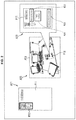
- the object OB 11 is an object which is a recognition target when a pose of the camera CA 21 is tracked, and the camera CA 21 stores a three-dimensional shape model of the object OB 11 .
- the object OB 12 is an object which is not a recognition target when the pose of the camera CA 21 is tracked.
- an input image P 51 can be obtained.
- the input image P 51 is drawn at a position on a projection surface determined from the pose of the camera CA 21 , a focal length of the camera CA 21 , or the like.
- a pose of the object OB 11 in the world coordinate system that is, the position, the posture and the shape of the object OB 11 are known by a three-dimensional shape model of the object OB 11 which is a recognition target. Therefore, it is possible specify whether or not each of the ray vector L 11 to the ray vector L 14 intersects the object OB 11 in real space.
- the camera CA 21 selects a feature point where the ray vector intersects the object OB 11 which is a recognition target among the feature points detected from the input image P 51 , and registers a portion of the object OB 11 corresponding to the selected feature point, that is, a position of the intersection point between the ray vector and the recognition target as a landmark. Adversely, the camera CA 21 does not register a portion of the subject corresponding to the feature point as a landmark for feature points where the ray vector does not intersect the object OB 11 which is the recognition target.
- the portion FC 13 corresponding to the feature point FP 23 and the portion FC 14 corresponding to the feature point FP 24 are registered as landmarks in the three-dimensional map.
- a region including the feature point FP 23 in the input image P 51 is made a template image, and the template image and the coordinate of the portion FC 13 in the world coordinate system are registered in the three-dimensional map.
- a region including the feature point FP 24 in the input image P 51 is made a template image, and the template image and the coordinate of the portion FC 14 in the world coordinate system are registered in the three-dimensional map.
- a method in which ray received within an angle of view of the camera CA 21 is tracked in a reverse direction centering around the point of view of the camera CA 21 through arithmetic operation processing, and a subject located in the direction is specified, is called a ray tracing method.
- a portion of the recognition target corresponding to the feature point is registered as a landmark in the three-dimensional map.
- a region which is made a recognition target to be used for initialization of the pose that is, a target for which a dictionary is to be generated, and a recognition target upon tracking of the pose will be described.
- a form portion on the card P 61 disposed in real space is made a target for which a dictionary is to be generated.
- the card P 61 includes a region R 51 of illustration printed in advance, a region R 52 of characters printed in advance and a region R 53 of characters written in the card P 61 .
- the message card includes a form portion such as a stamp and illustration printed in advance, and a non-form portion such as recipient's name and message written by a user, or the like.
- the form portion is a portion including texture and thus a region where a feature point can be detected, and is a portion whose position, pattern, or the like, are known in advance, the form portion is a region which can be utilized for pre-learning,
- the non-form portion is a portion written afterward in a message card, or the like, the non-form portion is a region which has low versatility and which is not suitable to be utilized for pre-learning. However, because a feature point can be detected from the non-form portion, the non-form portion can be used for learning an ambient environment online for tracking the pose.
- the whole card P 61 includes the region R 51 and the region R 52 which are form portions, and the region R 53 which is a non-form portion, it is possible to register an appropriate landmark in the three-dimensional map. Note that, in this case, because the shape of the card P 61 is substantially a two-dimensional shape, shape information of the three-dimensional shape model becomes information indicating a two-dimensional rectangular region.
- a three-dimensional object as well as a two-dimensional object as a recognition target.
- a three-dimensional object as well as a two-dimensional object as a recognition target.
- a cylindrical object as a recognition target.
- the three-dimensional map is generated and updated using the whole cylindrical recognition target P 71 as a recognition target upon tracking of the pose. Because it is possible to obtain the three-dimensional shape of such a recognition target P 71 through simple calculation, it is possible to easily obtain the three-dimensional shape model.
- the present technology can be also applied to a dynamic environment such as outdoors.
- a dictionary for initialization is generated using a portion of a region R 71 using the region R 71 which is part of a building P 81 located outdoors as a recognition target upon initialization.
- the three-dimensional map is generated and updated while a region R 72 of the whole building P 81 is made a recognition target upon tracking of the pose.
- the building P 81 is a substantially rectangular parallelepiped, it is possible to easily construct the three-dimensional shape model.
- FIG. 9 is a diagram illustrating a configuration example of an embodiment of an image processing apparatus to which the present technology is applied.
- the image processing apparatus 11 illustrated in FIG. 9 includes a photographing unit 21 , a pyramid image generating unit 22 , a feature point detecting unit 23 , a dictionary storage unit 24 , a matching unit 25 , an initial pose estimating unit 26 , a pose predicting unit 27 , a matching unit 28 , a pose estimating unit 29 , a determining unit 30 , a three-dimensional shape model storage unit 31 , a three-dimensional map updating unit 32 and a three-dimensional map storage unit 33 .
- the photographing unit 21 which is configured with a camera, or the like, photographs a subject around the image processing apparatus 11 in real space, and supplies an input image obtained as a result of the photographing to the pyramid image generating unit 22 .
- the pyramid image generating unit 22 performs up-sampling or down-sampling on the input image supplied from the photographing unit 21 , generates a plurality of images whose scales are different from each other as pyramid images and supplies these pyramid images to the feature point detecting unit 23 .
- the feature point detecting unit 23 detects feature points from each pyramid image supplied from the pyramid image generating unit 22 and extracts a feature amount of each of the detected feature points from each pyramid image.
- the feature point detecting unit 23 supplies information indicating positions of the feature points detected from the pyramid images and a feature amount of each feature point to the matching unit 25 and the pose predicting unit 27 as a detection result of the feature points.
- the dictionary storage unit 24 stores a dictionary for recognizing an object on the input image through object recognition, generated through pre-learning and supplies the stored dictionary to the matching unit 25 .
- the dictionary stored by the dictionary storage unit 24 is a dictionary for initializing the pose of the image processing apparatus 11 .
- the dictionary is formed with positions of the feature points detected from the region of the recognition target upon initialization in an image for learning, a feature amount extracted from the vicinity of the feature points of the image for learning, and size information indicating a size of the recognition target upon initialization in real space.
- the size information For example, in the example described with reference to FIG. 4 , information indicating a length x in a lateral direction and a length y in a longitudinal direction of the region 142 of a stamp portion which is a recognition target is made the size information. Further, the feature amount of each feature point is made, for example, a template image which is an image of the region in the vicinity of the feature point of the image for learning, and the template image is prepared for each scale of the image for learning.
- the matching unit 25 performs matching processing on the basis of the detection result of the feature points supplied from the feature point detecting unit 23 and the dictionary supplied from the dictionary storage unit 24 and supplies a result of the matching processing, the detection result of the feature points and the size information of the dictionary to the initial pose estimating unit 26 .
- the initial pose estimating unit 26 estimates an initial pose of the image processing apparatus 11 on the basis of the result of the matching processing and the size information supplied from the matching unit 25 and outputs the estimation result to a block in the subsequent stage. Further, the initial pose estimating unit 26 supplies the estimation result of the initial pose and the detection result of the feature points to the three-dimensional map updating unit 32 .
- the pose predicting unit 27 predicts the pose of the image processing apparatus 11 on the basis of the detection result of the feature points supplied from the feature point detecting unit 23 and supplies the prediction result and the detection result of the feature points to the matching unit 28 .
- the matching unit 28 performs matching processing on the basis of the prediction result of the pose and the detection result of the feature points supplied from the pose predicting unit 27 and the three-dimensional map stored in the three-dimensional map storage unit 33 and supplies the result of the matching processing and the detection result of the feature points to the pose estimating unit 29 .
- the pose estimating unit 29 estimates the pose of the image processing apparatus 11 on the basis of the result of the matching processing and the detection result of the feature points supplied from the matching unit 28 and outputs the estimation result to a block in the subsequent stage. That is, the pose estimating unit 29 tracks the pose. Further, the pose estimating unit 29 supplies the estimation result of the pose of the image processing apparatus 11 , the result of the matching processing and the detection result of the feature points to the three-dimensional map updating unit 32 .
- the determining unit 30 determines the three-dimensional shape model and supplies the determined three-dimensional shape model to the three-dimensional shape model storage unit 31 .
- the three-dimensional shape model storage unit 31 stores the three-dimensional shape model supplied from the determining unit 30 and supplies the three-dimensional shape model to the three-dimensional map updating unit 32 as necessary.
- the three-dimensional map updating unit 32 generates a three-dimensional map on the basis of the estimation result of the initial pose and the detection result of the feature points supplied from the initial pose estimating unit 26 and the three-dimensional shape model supplied from the three-dimensional shape model storage unit 31 and supplies the three-dimensional map to the three-dimensional map storage unit 33 .
- the three-dimensional map updating unit 32 updates the three-dimensional map stored in the three-dimensional map storage unit 33 on the basis of the estimation result of the pose supplied from the pose estimating unit 29 , the result of the matching processing, the detection result of the feature points, and the three-dimensional shape model supplied from the three-dimensional shape model storage unit 31 . That is, an updated new three-dimensional map is generated.
- the three-dimensional map storage unit 33 stores the three-dimensional map supplied from the three-dimensional map updating unit 32 and supplies the stored three-dimensional map to the matching unit 28 as necessary.
- the image processing apparatus 11 When the image processing apparatus 11 is instructed to estimate the pose of the image processing apparatus 11 itself, the image processing apparatus 11 starts photographing of the input image by the photographing unit 21 and performs pose estimation processing to estimate the pose of the image processing apparatus 11 at each time.
- the pose estimation processing by the image processing apparatus 11 will be described below with reference to the flowchart in FIG. 10 .
- an input image at each time is photographed by the photographing unit 21 while an object such as a recognition target in real space (three-dimensional space) is made a subject, and the input image obtained as a result of the photographing is sequentially supplied to the pyramid image generating unit 22 .
- step S 11 the determining unit 30 determines a three-dimensional shape model and supplies the determined three-dimensional shape model to the three-dimensional shape model storage unit 31 to make the three-dimensional shape model storage unit 31 store the three-dimensional shape model.
- the determining unit 30 determines the three-dimensional shape model by acquiring the three-dimensional shape model from a server, or the like, via a communication network or acquiring the three-dimensional shape model recorded in the image processing apparatus 11 .
- the determining unit 30 may determine the three-dimensional shape model on the basis of a designated value from outside, such as through input operation by the user.
- a value for specifying the shape and the position of the three-dimensional shape model is designated by the designated value, and the determining unit 30 determines the three-dimensional shape model on the basis of the designated value and constructs the three-dimensional shape model according to the determination.
- step S 12 the feature point detecting unit 23 detects feature points from the input image.
- the pyramid image generating unit 22 generates a pyramid image of each scale on the basis of the input image supplied from the photographing unit 21 and supplies the pyramid image to the feature point detecting unit 23 .
- the feature point detecting unit 23 detects feature points from the pyramid image of each scale supplied from the pyramid image generating unit 22 according to algorithm such as Harris corner and extracts a feature amount of the feature point for each feature point of the pyramid image of each scale.
- the feature point detecting unit 23 cuts out a region in the vicinity of the feature point in the pyramid image and makes a template image obtained as a result of cutout a feature amount.
- a feature amount of each feature point is not limited to the template image, and may be any feature amount such as a scale invariant feature transform (SIFT) feature amount.
- SIFT scale invariant feature transform
- the feature point detecting unit 23 supplies information indicating the positions of the feature points detected on the pyramid image of each scale and the template image of each feature point to the matching unit 25 as a detection result of the feature points.
- the feature amount obtained at the feature point detecting unit 23 is a template image for each scale of each feature point detected from the input image.
- step S 13 the matching unit 25 performs matching processing on the basis of a detection result of the feature points supplied from the feature point detecting unit 23 and the dictionary supplied from the dictionary storage unit 24 .
- the matching unit 25 calculates a degree of similarity between the template image of the feature points registered in the dictionary and the template image of the feature points detected from the pyramid image. That is, a degree of similarity between the feature points registered in the dictionary and the feature points detected from the pyramid image is calculated.
- any types of the degree of similarity are possible such as, for example, zero mean normalized cross correlation (ZNCC), normalized cross correlation (NCC), sum of absolute difference (SAD) and sum of squared difference (SSD). Further, the degree of similarity is calculated for each scale of the pyramid image for the template image of each scale of the feature points registered in the dictionary.
- ZNCC zero mean normalized cross correlation
- NCC normalized cross correlation
- SAD sum of absolute difference
- SSD sum of squared difference
- a pair of feature points with the highest degree of similarity that is, a pair of a feature point registered in the dictionary and a feature point in the pyramid image with the highest degree of similarity with the feature point is obtained for each feature point registered in the dictionary.
- the feature point registered in the dictionary and the pyramid image which is paired with the feature point that is, the feature point on the input image are feature points detected from the same portion of the subject in real space.
- the two feature points which are paired will be also referred to as feature points corresponding to each other.
- the matching unit 25 obtains information indicating the feature points which are paired obtained in this manner as a result of the matching processing and supplies the result of the matching processing, the detection result of the feature points and the size information included in the dictionary to the initial pose estimating unit 26 .
- step S 14 the initial pose estimating unit 26 estimates an initial pose of the image processing apparatus 11 on the basis of the result of the matching processing and the size information supplied from the matching unit 25 and outputs the estimation result to a block in the subsequent stage.
- the initial pose can be obtained through estimation from positional relationship between the feature points in the image for learning of the dictionary, positional relationship between the feature points on the input image (pyramid image) corresponding to the feature points, positional relationship between the feature points which are paired and the size information. That is, the position and the posture of the image processing apparatus 11 in the world coordinate system when the input image is photographed can be obtained as the initial pose.
- a position of the recognition target upon initialization for example, a position of a midpoint of the feature points registered in the dictionary, or the like, is made the origin of the world coordinate system.
- the initial pose obtained in this manner becomes the own pose which becomes a reference when tracking of the pose is started.
- the initial pose estimating unit 26 supplies the estimation result of the initial pose and the detection result of the feature points to the three-dimensional map updating unit 32 .
- step S 15 the three-dimensional map updating unit 32 generates a three-dimensional map on the basis of the estimation result of the initial pose and the detection result of the feature points supplied from the initial pose estimating unit 26 , and the three-dimensional shape model supplied from the three-dimensional shape model storage unit 31 .
- the three-dimensional map updating unit 32 generates a three-dimensional map using the ray tracing method as described with reference to FIG. 5 .
- the three-dimensional map updating unit 32 obtains a ray vector which passes the point of view of the photographing unit 21 and the feature points on the projection image from the initial pose of the image processing apparatus 11 , and the positions of the feature points on the projection image, that is, the positions (projection positions) of the feature points detected from the input image (pyramid image) in the world coordinate system.
- the three-dimensional updating unit 32 selects a feature point where the recognition target upon tracking of the pose intersects the ray vector on the world coordinate system, determined by the three-dimensional shape model. Further, the three-dimensional map updating unit 32 registers an intersection position (position of the intersection point) between the ray vector and the recognition target obtained for the selected feature point in the three-dimensional map as the landmark.
- the three-dimensional map updating unit 32 makes a coordinate of the position of the intersection point between the ray vector and the recognition target in the world coordinate system a coordinate of the landmark, and generates the three-dimensional map using the template image obtained from the pyramid image of each scale for the feature point corresponding to the landmark as the feature amount of the landmark.
- the three-dimensional map updating unit 32 supplies the three-dimensional map obtained in this manner to the three-dimensional map storage unit 33 to make the three-dimensional map storage unit 33 store the three-dimensional map.
- the pose of the image processing apparatus 11 is tracked thereafter on the basis of the input image photographed at each time.
- step S 16 the feature point detecting unit 23 detects feature points from the input image. Note that, because the processing of step S 16 is similar to the processing of step S 12 , description thereof will be omitted. However, in step S 16 , the feature point detecting unit 23 supplies the detection result of the feature points to the pose predicting unit 27 .
- step S 17 the pose predicting unit 27 predicts the pose of the image processing apparatus 11 on the basis of the detection result of the feature points supplied from the feature point detecting unit 23 and supplies the prediction result and the detection result of the feature points to the matching unit 28 .
- the pose predicting unit 27 calculates a rough pose of the image processing apparatus 11 at current time as a predicted pose by performing filter operation using an extended Kalman filter on the basis of the positions of the feature points detected from the pyramid image of each scale.
- step S 18 the matching unit 28 selects a landmark to be used for matching processing on the basis of the prediction result of the pose supplied from the pose predicting unit 27 and the three-dimensional map stored in the three-dimensional map storage unit 33 .
- a field of view of the photographing unit 21 in the world coordinate system is known from the predicted pose of the image processing apparatus 11 , it is possible to specify a landmark observed within the field of view of the photographing unit 21 at current time from the field of view of the photographing unit 21 and the position of each landmark on the world coordinate system indicated by the three-dimensional map. That is, it is possible to specify a landmark to be observed on the input image of a current frame.
- the matching unit 28 selects a landmark observed within the field of view of the photographing unit 21 at current time as a landmark to be used for matching processing. Note that, in the following description, the landmark selected in the processing of step S 18 will be also referred to as a known landmark.
- step S 19 the matching unit 28 performs matching processing on the basis of the detection result of the feature points supplied from the pose predicting unit 27 and the feature amount of the known landmark registered in the three-dimensional map stored in the three-dimensional map storage unit 33 .
- step S 19 template matching which is similar to the processing of step S 13 is performed as the matching processing.
- the matching unit 28 calculates a degree of similarity between the template image of each scale which is a feature amount of the known landmark and the template image of the feature points detected from the pyramid image of each scale. That is, a degree of similarity between the known landmark and the feature points detected from the pyramid image is calculated.
- the degree of similarity of the template image may be any value such as ZNCC, NCC, SAD and SSD.
- the matching unit 28 makes information indicating the known landmark and the feature points which are to be paired, obtained in this manner, a result of the matching processing, and supplies the result of the matching processing, the detection result of the feature points and the coordinate of the known landmark in the world coordinate system to the pose estimating unit 29 .
- step S 20 the pose estimating unit 29 estimates the pose of the image processing apparatus 11 at current time (current frame) on the basis of the result of the matching processing, the detection result of the feature points and the coordinate of the known landmark in the world coordinate system supplied from the matching unit 28 . That is, the position and the posture of the image processing apparatus 11 when the input image is photographed in tracking of the pose, in the world coordinate system, are obtained as the pose.
- the pose is estimated using a method such as P3P and random sample consensus (RANSAC).
- the pose estimating unit 29 outputs the estimation result of the pose of the image processing apparatus 11 to a block in the subsequent stage. Further, the pose estimating unit 29 supplies the result of the matching processing, the estimation result of the pose of the image processing apparatus 11 and the detection result of the feature points to the three-dimensional map updating unit 32 .
- step S 21 the three-dimensional map updating unit 32 updates the known landmark in the three-dimensional map stored in the three-dimensional map storage unit 33 on the basis of the result of the matching processing and the detection result of the feature points supplied from the pose estimating unit 29 .
- the three-dimensional map updating unit 32 extracts a template image which is a feature amount of the feature point corresponding to the known landmark among the feature amounts of respective feature points obtained as the detection result of the feature points on the basis of the result of the matching processing.
- the three-dimensional map updating unit 32 then updates the three-dimensional map by adding the extracted template image as the feature amount of the known landmark in the three-dimensional map.
- step S 22 the three-dimensional map updating unit 32 obtains a ray vector of a new feature point on the basis of the result of the matching processing, the estimation result of the pose of the image processing apparatus 11 and the detection result of the feature points supplied from the pose estimating unit 29 .
- the three-dimensional map updating unit 32 makes all the feature points different from the feature point corresponding to the known landmark among the feature points detected from the input image, new feature points on the basis of the result of the matching processing and the detection result of the feature points.
- the three-dimensional map updating unit 32 then obtains a ray vector which passes the position of the point of view of the photographing unit 21 and the new feature point for each of the new feature points on the basis of the positions of the new feature points on the projection image in the world coordinate system, obtained from the estimation result of the pose of the image processing apparatus 11 and the detection result of the feature points.
- step S 23 the three-dimensional map updating unit 32 registers a new landmark on the basis of the ray vector of the new feature point, the three-dimensional shape model stored in the three-dimensional shape model storage unit 31 and the detection result of the feature points.
- the three-dimensional map updating unit 32 specifies (determines) whether or not the ray vector of the new feature point intersects the recognition target on the world coordinate system indicated with the three-dimensional shape model, for each new feature point.
- the three-dimensional map updating unit 32 does not register a landmark of a portion corresponding to the new feature point assuming that the new feature point is not a projection point of the portion of the recognition target.
- the three-dimensional map updating unit 32 registers the landmark of the portion corresponding to the new feature point assuming that the new feature point is a projection point of the portion of the recognition target.
- the three-dimensional map updating unit 32 adds the coordinate of the position of the intersection of the ray vector obtained for the new feature point and the recognition target on the world coordinate system and the template image of each scale which is the feature amount obtained for the new feature point as information relating to the new landmark corresponding to the new feature point.
- the processing After the new landmark is registered in the three-dimensional map in this manner, and the three-dimensional map stored in the three-dimensional map storage unit 33 is updated, the processing returns to step S 16 , and the above-described processing is repeatedly performed. If it is instructed to finish estimation of the pose, the pose estimation processing is finished.
- the new landmark may be registered for a new feature point tier which a distance between the recognition target and the ray vector in the world coordinate system is equal to or less than a predetermined threshold.
- a portion of the recognition target, closest to the ray vector is made a portion corresponding to the new feature point, and the portion is registered in the three-dimensional map as a new landmark. Further, for example, a position on the ray vector closest to the recognition target may be made a new landmark corresponding to the new feature point and may be registered in the three-dimensional map.
- the three-dimensional map is generated and updated as illustrated in FIG. 11 .
- an input image P 91 including as a subject the recognition target OB 21 whose pose and shape on the world coordinate system are specified with the three-dimensional shape model is photographed. Further, it is assumed that a feature point FP 41 corresponding to a portion FC 31 on the recognition target OB 21 is detected from the input image P 91 , and an initial pose of the image processing apparatus 11 is obtained on the basis of the input image P 91 and the dictionary learned in advance.
- step S 15 in three-dimensional map generation processing in step S 15 , the portion FC 31 on the recognition target OB 21 corresponding to the feature point FP 41 is registered as a landmark, and a template image including the feature point FP 41 is made a feature amount of the landmark.
- a feature point FP 42 corresponding to the portion FC 31 of the recognition target OB 21 and a feature point FP 43 corresponding to the portion FC 32 of the recognition target OB 21 are detected from the input image P 92 .
- the portion FC 31 is selected as the known landmark in step S 18 , and matching processing in step S 19 is performed. That is, matching between a template image including the feature point FP 42 and a template image including the feature point FP 41 registered in the three-dimensional map is performed, and it can be known that the feature point FP 42 corresponds to the portion FC 31 .
- the pose of the image processing apparatus 11 at time when the input image P 92 is photographed is estimated on the basis of the result of the matching processing, or the like.
- step S 21 the three-dimensional map is updated by the template image including the feature point FP 42 being added as the feature amount of the portion FC 31 which is the known landmark.
- step S 22 a ray vector L 21 connecting a point of view VP 11 of the photographing unit 21 and a feature point FP 43 is obtained for the feature point FP 43 which is a new feature point.
- step S 23 because the ray vector L 21 intersect the recognition target OB 21 at the portion FC 32 of the recognition target OB 21 , in step S 23 , the portion FC 32 is registered in the three-dimensional map as a new landmark. That is, the portion FC 32 on the recognition target OB 21 corresponding to the feature point FP 43 is registered as the landmark, and the template image including the feature point FP 43 is made a feature amount of the landmark.
- estimation of the pose of the image processing apparatus 11 and updating of the three-dimensional map are continuously performed on the basis of the input image photographed at each time.
- the image processing apparatus 11 estimates the initial pose on the basis of the input image and the dictionary and generates the three-dimensional map from the estimation result and the three-dimensional shape model. Further, the image processing apparatus 11 tracks the pose on the basis of the input image and the three-dimensional map and updates the three-dimensional map on the basis of the pose of the image processing apparatus 11 and the three-dimensional shape model.
- the pose may be initialized using any method.
- the initial pose of the image processing apparatus may be measured using a sensor, or the like.
- the image processing apparatus is configured as illustrated in FIG. 12 .
- FIG. 12 the same reference numerals are assigned to portions corresponding to those in FIG. 9 , and description thereof will be omitted as appropriate.
- the image processing apparatus 61 illustrated in FIG. 12 includes a photographing unit 21 , a pyramid image generating unit 22 , a feature point detecting unit 23 , a position measuring unit 71 , an acceleration sensor 72 , a geomagnetic sensor 73 , a posture estimating unit 74 , an initial pose estimating unit 75 , a pose predicting unit 27 , a matching unit 28 , a pose estimating unit 29 , a determining unit 30 , a three-dimensional shape model storage unit 31 , a three-dimensional map updating unit 32 and a three-dimensional map storage unit 33 .
- the configuration of the image processing apparatus 61 is different from the configuration of the image processing apparatus 11 in that, in place of the dictionary storage unit 24 to the initial pose estimating unit 26 of the image processing apparatus 11 illustrated in FIG. 9 , the position measuring unit 71 to the initial pose estimating unit 75 are provided, and the configuration of the image processing tri apparatus 61 is the same as the configuration of the image processing apparatus 11 in other points.
- the position measuring unit 71 which is configured with a GPS sensor, or the like, measures the own position, that is, a position (coordinate) of the image processing apparatus 61 on the world coordinate system and supplies the measurement result to the initial pose estimating unit 75 .
- the position measuring unit 71 obtains a coordinate indicating the position of the image processing apparatus 61 in the world coordinate system by obtaining a distance from each satellite to the image processing apparatus 61 on the basis of radio waves received from some satellites.
- the position measuring unit 71 is not limited to the GPS sensor, and may be any sensor if the position of the image processing apparatus 61 in the world coordinate system can be measured.
- the position measuring unit 71 may measure the position of the image processing apparatus 61 by utilizing Wi-Fi (registered trademark). In this case, the position measuring unit 71 measures a distance from the image processing apparatus 61 to each access point on the basis of strength of signals from some access points whose positions in the world coordinate system are known, and obtains the position of the image processing apparatus 61 in the world coordinate system on the basis of the measurement result of the distances.
- Wi-Fi registered trademark
- the acceleration sensor 72 measures own inclination based on a horizontal plane of the earth, that is, inclination of the image processing apparatus 61 with respect to the horizontal plane of the earth and inclination of the image processing apparatus 61 with respect to a vertical plane perpendicular to the horizontal plane of the earth and supplies the measurement result to the posture estimating unit 74 .
- the geomagnetic sensor 73 which is a so-called electronic compass, measures a direction of the image processing apparatus 61 on the horizontal plane of the earth, that is, a direction the image processing apparatus 61 faces, and supplies the measurement result to the posture estimating unit 74 .
- the posture estimating unit 74 estimates the posture of the image processing apparatus 61 on the basis of the measurement result from the acceleration sensor 72 and the measurement result from the geomagnetic sensor 73 and supplies the estimation result to the initial pose estimating unit 75 .
- the initial pose estimating unit 75 estimates the initial pose of the image processing apparatus 61 on the basis of output from the position measuring unit 71 which measures the own position, output from the acceleration sensor 72 which measures the own inclination, and output from the geomagnetic sensor 73 which measures the own orientation.
- the initial pose estimating unit 75 obtains the estimation result of the initial pose of the image processing apparatus 61 by integrating the estimation result of the posture supplied from the posture estimating unit 74 and the measurement result of the position supplied from the position measuring unit 71 and supplies the obtained estimation result of the initial pose to a block in the subsequent stage and the three-dimensional map updating unit 32 .
- the detection result of the feature points obtained at the feature point detecting unit 23 is supplied to the three-dimensional map updating unit 32 and the pose predicting unit 27 .
- pose estimation processing performed by the image processing apparatus 61 will be described with reference to the flowchart in FIG. 13 .
- step S 51 and step S 52 are similar to the processing of step S 11 and step S 12 in FIG. 10 , description thereof will be omitted.
- the feature point detecting unit 23 supplies the detection result of the feature points to the three-dimensional map updating unit 32 .
- step S 53 the position measuring unit 71 measures a position (coordinate) of the image processing apparatus 61 on the world coordinate system and supplies the measurement result to the initial pose estimating unit 75 .
- step S 54 the acceleration sensor 72 measures inclination of the image processing apparatus 61 with respect to the horizontal plane of the earth and inclination of the image processing apparatus 61 with respect to the vertical plane and supplies the measurement result to the posture estimating unit 74 .
- step S 55 the geomagnetic sensor 73 measures a direction of the image processing apparatus 61 on the horizontal plane of the earth and supplies the measurement result to the posture estimating unit 74 .
- step S 56 the posture estimating unit 74 estimates the posture of the image processing apparatus 61 on the basis of the measurement result from the acceleration sensor 72 and the measurement result from the geomagnetic sensor 73 and supplies the estimation result to the initial pose estimating unit 75 .
- the posture estimating unit 74 calculates a rotation matrix indicating a rotation amount of the image processing apparatus 61 with respect to the posture which is a reference from the inclination of the image processing apparatus 61 with respect to the horizontal plane of the earth and the vertical plane and the direction of the image processing apparatus 61 with respect to the horizontal plane of the earth and sets the rotation matrix as the estimation result of the posture of the image processing apparatus 61 .
- the initial pose estimating unit 75 estimates the initial pose of the image processing apparatus 61 . That is, the initial pose estimating unit 75 obtains the estimation result of the initial pose of the image processing apparatus 61 by integrating the estimation result of the posture supplied from the posture estimating unit 74 and the measurement result of the position supplied from the position measuring unit 71 and supplies the obtained estimation result of the pose to a block in the subsequent stage and the three-dimensional map updating unit 32 .
- step S 58 to step S 66 is performed, and, then, processing from step S 59 to step S 66 is repeatedly performed.
- step S 59 to step S 66 is repeatedly performed.
- step S 58 to step S 66 is similar to the processing from step S 15 to step S 23 in FIG. 10 , description thereof will be omitted.
- the three-dimensional map updating unit 32 generates a three-dimensional map on the basis of the estimation result of the initial pose supplied from the initial pose estimating unit 75 , the detection result of the feature points supplied from the feature point detecting unit 23 and the three-dimensional shape model supplied from the three-dimensional shape model storage unit 31 .
- the image processing apparatus 61 estimates the initial pose on the basis of the measurement results by the position measuring unit 71 to the geomagnetic sensors 73 and generates a three-dimensional map using the estimation result and the three-dimensional shape model. Further, the image processing apparatus 61 tracks the pose on the basis of the input image and the three-dimensional map and updates the three-dimensional map on the basis of the pose of the image processing apparatus 61 and the three-dimensional shape model.
- a region R 81 of a portion of a building group located outdoors is made a recognition target upon initialization
- a region R 82 of the whole building group is made a recognition target upon tracking of the pose.
- by dividing the region R 82 into some regions with grids, and uniformly registering landmarks in each divided region (hereinafter, also referred to as a divided region), it is possible to estimate the pose more robustly and accurately.
- a degree of likeness of a feature point obtained at each position of the input image is compared with a threshold th, and a position where the degree of the likeness of the feature point is equal to or greater than the threshold th is made a feature point.
- the three-dimensional shape model only has to include a plurality of positions of respective divided regions, that is, information indicating ranges of respective divided regions at the recognition target.
- the image processing apparatus 11 is configured as illustrated in, for example, FIG. 15 .
- the same reference numerals are assigned to portions corresponding to the portions in FIG. 9 , and description thereof will be omitted as appropriate.
- the image processing apparatus 11 illustrated in FIG. 15 includes a photographing unit 21 , a pyramid image generating unit 22 , a feature point detecting unit 23 , a dictionary storage unit 24 , a matching unit 25 , an initial pose estimating unit 26 , a pose predicting unit 27 , a matching unit 28 , a pose estimating unit 29 , a determining unit 30 , a three-dimensional shape model storage unit 31 , a three-dimensional map updating unit 32 and a three-dimensional map storage unit 33 .
- the three-dimensional map updating unit 32 controls feature point detection processing at the feature point detecting unit 23 according to the registration status of landmarks in each divided region of the recognition target upon tracking of the pose.
- the three-dimensional shape model stored in the three-dimensional shape model storage unit 31 is formed with shape information, the external parameter and information indicating positions of respective divided regions.
- step S 91 to step S 103 is similar the processing from step S 11 to step S 23 in FIG. 10 , description thereof will be omitted.
- the feature point detecting unit 23 detects feature points while changing the threshold th for detecting feature points for each region of the pyramid image (input image) according to an instruction from the three-dimensional map updating unit 32 .
- step S 104 the three-dimensional map updating unit 32 determines the threshold th for each of a plurality of divided regions of the recognition target and supplies the determination result to the feature point detecting unit 23 .
- the three-dimensional map updating unit 32 specifies the number of landmarks registered within the divided region for each divided region of the recognition target from the three-dimensional shape model stored in the three-dimensional shape model storage unit 31 and the three-dimensional map stored in the three-dimensional map storage unit 33 .
- the three-dimensional map updating unit 32 determines the threshold th for the divided region according to the number of landmarks within the divided region.
- the three-dimensional map updating unit 32 resets the threshold th of the divided region to a greater value for the divided region where the number of landmarks which have already been registered is equal to or larger than a predetermined number, so as to make it difficult that a new landmark is registered within the divided region. That is, it is made difficult to detect feature points from a region corresponding to the divided region on the input image.
- the three-dimensional map updating unit 32 resets the threshold th of the divided region to a smaller value for the divided region where the number of registered landmarks is less than the predetermined number, so as to make it easier that a new landmark is registered in the divided region.
- the threshold th of each divided region may be changed in a stepwise manner according to the number of landmarks registered in each divided region.
- the three-dimensional map updating unit 32 specifies the position (range) of each divided region in the input image of a current frame (current time) on the basis of the pose of the image processing apparatus 11 at current time and the three-dimensional shape model. That is, a region in which the divided region appears in the input image is specified.
- the three-dimensional map updating unit 32 then supplies the specification result of the positions of the respective divided regions in the input image and the threshold th for each divided region to the feature point detecting unit 23 and controls detection of the feature points from an input image of the next frame.
- the three-dimensional map updating unit 32 controls the feature point detecting unit 23 so that feature points are detected using the threshold th determined for the divided region in the region of the input image of the next frame, located at the same position as the region which is the divided region of the input image of the current frame.
- the three-dimensional map updating unit 32 controls detection of the feature points assuming that the region corresponding to the divided region in the input image of the next frame is located at the same position as the region corresponding to the divided region in the input image of the current frame.
- step S 96 After the threshold th is determined for each divided region, the processing returns to step S 96 and the above-described processing is repeatedly performed.
- step S 96 the feature point detecting unit 23 specifies each divided region on the pyramid image according to control by the three-dimensional map updating unit 32 and detects feature points using the threshold th determined for each divided region for the specified divided regions.
- the image processing apparatus 11 determines the threshold th of the divided region according to the registration status of the landmark in each divided region and detects feature points from the input image using the determined threshold th.
- landmarks are evenly registered in each divided region, so that it is possible to estimate the pose more robustly and accurately.
- landmarks may be intensively registered from a region of part of the recognition target upon tracking of the pose.
- FIG. 17 the same reference numerals are assigned to portions corresponding to the portions in FIG. 14 , and description thereof will be omitted as appropriate.
- a region R 91 which is part of the region R 82 which is made the recognition target is designated as an important region.
- any method can be used as a method for designating the important region, such as designation of the important region from the region R 82 of the recognition target on the input image by the user, or the like, and designation of a region which is made the important region from a plurality of regions which are candidates for the important region by the user, or the like.
- the important region may be determined in advance, in which case, it is only necessary to make the three-dimensional shape model include information indicating the position (range) of the important region.
- the region R 91 which is part of the region R 82 which is made the recognition target is made the important region in this manner, when the important region appears as the subject in the input image, if the threshold th in the important region on the input image is made lower, feature points are detected more easily from the important region than from other regions.
- landmarks are intensively registered, that is, more landmarks are registered in the region R 91 .
- the image processing apparatus 11 is configured as illustrated in, for example, FIG. 15 . Further, the three-dimensional shape model stored in the three-dimensional shape model storage unit 31 of the image processing apparatus 11 is formed with shape information, the external parameter and information indicating the position (range) of the important region.
- step S 131 to step S 143 is similar to the processing from step S 11 to step S 23 in FIG. 10 , description thereof will be omitted.
- the feature point detecting unit 23 detects feature points while changing the threshold th for detecting feature points for each region of the pyramid image (input image) according to an instruction from the three-dimensional map updating unit 32 .
- step S 144 the three-dimensional map updating unit 32 determines the threshold th of each region and supplies the determination result to the feature point detecting unit 23 .
- the three-dimensional map updating unit 32 specifies the position (range) of the important region in the input image of the current frame (current time) on the basis of the pose of the image processing apparatus 11 at current time and the three-dimensional shape model. That is, a region where the important region appears in the input image is specified.
- the three-dimensional map updating unit 32 sets a lower threshold th than the normal threshold th for the important region, in more detail, a region where the important region appears as the subject. Further, the threshold th determined in advance is set for a region other than the important region without change.
- the three-dimensional map updating unit 32 supplies the specification result of the position of the important region in the input image and the threshold th of the important region to the feature point detecting unit 23 and controls detection of feature points from the input image of the next frame.
- the three-dimensional map updating unit 32 controls the feature point detecting unit 23 so that feature points are detected using the threshold th determined for the important region in the region of the input image of the next frame located at the same position as the position of the region which is made the important region in the input image of the current frame.
- detection of feature points is controlled assuming that the region corresponding to the important region in the input image of the next frame is located at the same position as the position of the region corresponding to the important region in the input image of the current frame.
- the threshold th is not particularly changed. Further, in the case where there is an important region in the input image, the threshold th may be lowered for the whole input image instead of the threshold th being lowered for only for the important region.
- step S 136 After the threshold th of each region is determined, the processing returns to step S 136 , and the above-described processing is repeatedly performed.
- the feature point detecting unit 23 specifies an important region on the pyramid image according to control by the three-dimensional map updating unit 32 and detects feature points using the threshold th determined for the important region for the specified important region.
- the image processing apparatus 11 detects feature points from the input image using the threshold th while lowering the threshold th for the important region.
- portions within the important region are intensively registered as landmarks, so that it is possible to estimate the pose more robustly and accurately.
- the series of processes described above can be executed by hardware but can also be executed by software.
- a program that constructs such software is installed into a computer.
- the expression “computer” includes a computer in which dedicated hardware is incorporated and a general-purpose personal computer or the like that is capable of executing various functions when various programs are installed.
- FIG. 19 is a block diagram showing an example configuration of the hardware of a computer that executes the series of processes described earlier according to a program.
- a CPU Central Processing Unit
- ROM Read Only Memory
- RAM Random Access Memory
- An input/output interface 505 is also connected to the bus 504 .
- An input unit 506 , an output unit 507 , a recording unit 508 , a communication unit 509 , and a drive 510 are connected to the input/output interface 505 .
- the input unit 506 is configured from a keyboard, a mouse, a microphone, imaging element or the like.
- the output unit 507 configured from a display, a speaker or the like.
- the recording unit 508 is configured from a hard disk, a non-volatile memory or the like.
- the communication unit 509 is configured from a network interface or the like.
- the drive 510 drives a removable recording medium 511 such as a magnetic disk, an optical disk, a magneto-optical disk, a semiconductor memory or the like.
- the CPU 501 loads a program recorded in the recording unit 508 via the input/output interface 505 and the bus 504 into the RAM 503 and executes the program to carry out the series of processes described earlier.
- the program executed by the computer may be provided by being recorded on the removable recording medium 511 as a packaged medium or the like.
- the program can also be provided via a wired or wireless transfer medium, such as a local area network, the Internet, or a digital satellite broadcast.
- the program can be installed into the recording unit 508 via the input/output interface 505 . It is also possible to receive the program from a wired or wireless transfer medium using the communication unit 509 and install the program into the recording unit 508 . As another alternative, the program can be installed in advance into the ROM 502 or the recording unit 508 .
- the program executed by the computer may be a program in which processes are carried out in a time series in the order described in this specification or may be a program in which processes are carried out in parallel or at necessary timing, such as when the processes are called.
- the present disclosure can adopt a configuration of cloud computing which processes by allocating and connecting one function by a plurality of apparatuses through a network.
- each step described by the above-mentioned flow charts can be executed by one apparatus or by allocating a plurality of apparatuses.
- the plurality of processes included in this one step can be executed by one apparatus or by sharing a plurality of apparatuses.
- present technology may also be configured as below.
- An image processing apparatus including:
- a three-dimensional map generating unit configured to, on the basis of a shape model indicating a position and a shape of a recognition target in three-dimensional space and a detection result of a feature point from an input image obtained by photographing a subject in the three-dimensional space, register a portion of the recognition target corresponding to the feature point as a landmark and generate a three-dimensional map indicating a position of the landmark in the three-dimensional space.
- the three-dimensional map generating unit obtains a ray vector which passes a position of a point of view when the input image is photographed and a position of the feature point of the input image on a projection plane and generates the three-dimensional map on the basis of the ray vector and the shape model.
- the three-dimensional map generating unit registers a position where the recognition target intersects the ray vector in the three dimensional map as the landmark.
- the three-dimensional map generating unit registers a position in the recognition target closest to the ray vector in the three-dimensional map as the landmark.
- the image processing apparatus according to any one of (1) to (4), further including:
- a pose estimating unit configured to estimate a pose on the basis of the three-dimensional map and a detection result of the feature point from the input image.
- the pose estimating unit tracks the pose on the basis of the three-dimensional map and the detection result of the feature point from the input image.
- the three-dimensional map generating unit controls detection of the feature point for each region in a new input image on the basis of the number of the landmarks within each of a plurality of divided regions obtained by dividing a region of the recognition target, and a result of specifying a region corresponding to the divided region in the input image.
- the three-dimensional map generating unit controls detection of the feature point such that more feature points are detected from a region of the new input image corresponding to the divided region with less landmarks registered in the three-dimensional map.
- the three-dimensional map generating unit specifies a region corresponding to a specific region on the recognition target in the input image and controls detection of the feature point from the new input image on the basis of a result of specifying the region corresponding to the specific region.
- the three-dimensional map generating unit controls detection of the feature point such that more feature points are detected from the region corresponding to the specific region in the new input image.
- the image processing apparatus according to any one of (1) to (10), further including:
- an initial pose estimating unit configured to estimate an initial pose through object recognition on the basis of a detection result of the feature point from the input image and a dictionary obtained through learning in advance.
- the image processing apparatus according to any one of (1) to (10), further including:
- an initial pose estimating unit configured to estimate an initial pose on the basis of output from a sensor which measures a position of the image processing apparatus and output from a sensor which measure inclination of the image processing apparatus.
- the three-dimensional map generating unit generates the three-dimensional map on the basis of an estimation result of the initial pose, a detection result of the feature point from the input image, and the shape model.
- An image processing method including steps of:
- a shape model indicating a position and a shape of a recognition target in three-dimensional space and a detection result of a feature point from an input image obtained by photographing a subject in the three-dimensional space, registering a portion of the recognition target corresponding to the feature point as a landmark and generating a three-dimensional map indicating a position of the landmark in the three-dimensional space.
- a program causing a computer to execute processing including steps of:
- a shape model indicating a position and a shape of a recognition target in three-dimensional space and a detection result of a feature point from an input image obtained by photographing a subject in the three-dimensional space, registering a portion of the recognition target corresponding to the feature point as a landmark and generating a three-dimensional map indicating a position of the landmark in the three-dimensional space.
Applications Claiming Priority (3)
| Application Number | Priority Date | Filing Date | Title |
|---|---|---|---|
| JP2015119627 | 2015-06-12 | ||
| JP2015-119627 | 2015-06-12 | ||
| PCT/JP2016/065863 WO2016199605A1 (ja) | 2015-06-12 | 2016-05-30 | 画像処理装置および方法、並びにプログラム |
Publications (2)
| Publication Number | Publication Date |
|---|---|
| US20180150974A1 US20180150974A1 (en) | 2018-05-31 |
| US10636168B2 true US10636168B2 (en) | 2020-04-28 |
Family
ID=57503584
Family Applications (1)
| Application Number | Title | Priority Date | Filing Date |
|---|---|---|---|
| US15/575,199 Active 2036-11-19 US10636168B2 (en) | 2015-06-12 | 2016-05-30 | Image processing apparatus, method, and program |
Country Status (3)
| Country | Link |
|---|---|
| US (1) | US10636168B2 (ja) |
| EP (1) | EP3309751B1 (ja) |
| WO (1) | WO2016199605A1 (ja) |
Families Citing this family (17)
| Publication number | Priority date | Publication date | Assignee | Title |
|---|---|---|---|---|
| US10417533B2 (en) * | 2016-08-09 | 2019-09-17 | Cognex Corporation | Selection of balanced-probe sites for 3-D alignment algorithms |
| JP2018036901A (ja) * | 2016-08-31 | 2018-03-08 | 富士通株式会社 | 画像処理装置、画像処理方法および画像処理プログラム |
| JP7046506B2 (ja) * | 2017-06-12 | 2022-04-04 | キヤノン株式会社 | 情報処理装置、情報処理方法及びプログラム |
| WO2019019157A1 (en) * | 2017-07-28 | 2019-01-31 | Qualcomm Incorporated | INITIALIZING IMAGE SENSOR IN A ROBOTIC VEHICLE |
| CN109584295B (zh) * | 2017-09-29 | 2022-08-26 | 阿里巴巴集团控股有限公司 | 对图像内目标物体进行自动标注的方法、装置及系统 |
| JP7036400B2 (ja) * | 2018-01-30 | 2022-03-15 | 株式会社豊田中央研究所 | 自車位置推定装置、自車位置推定方法、及び自車位置推定プログラム |
| JP6863946B2 (ja) * | 2018-10-31 | 2021-04-21 | ファナック株式会社 | 画像処理装置 |
| WO2020115944A1 (ja) * | 2018-12-03 | 2020-06-11 | 株式会社Nttドコモ | マップデータ生成装置 |
| CN111260698B (zh) * | 2018-12-03 | 2024-01-02 | 北京魔门塔科技有限公司 | 双目图像特征匹配方法及车载终端 |
| CN111354042B (zh) * | 2018-12-24 | 2023-12-01 | 深圳市优必选科技有限公司 | 机器人视觉图像的特征提取方法、装置、机器人及介质 |
| US11836147B2 (en) * | 2019-03-25 | 2023-12-05 | Nec Corporation | Information processing apparatus, analysis system, data aggregation method, and computer readable medium |
| US11861863B2 (en) * | 2019-06-17 | 2024-01-02 | Faro Technologies, Inc. | Shape dependent model identification in point clouds |
| US11315326B2 (en) * | 2019-10-15 | 2022-04-26 | At&T Intellectual Property I, L.P. | Extended reality anchor caching based on viewport prediction |
| JP6815712B1 (ja) * | 2020-07-30 | 2021-01-20 | 株式会社マネーフォワード | 画像処理システム、画像処理方法、画像処理プログラム、画像処理サーバ、及び学習モデル |
| US11514695B2 (en) * | 2020-12-10 | 2022-11-29 | Microsoft Technology Licensing, Llc | Parsing an ink document using object-level and stroke-level processing |
| CN113362388A (zh) * | 2021-06-03 | 2021-09-07 | 安徽芯纪元科技有限公司 | 一种用于目标定位和姿态估计的深度学习模型 |
| CN114004885B (zh) * | 2021-10-18 | 2022-07-12 | 上海航天空间技术有限公司 | 利用卫星视线矢量对空中目标位置的快速估计方法 |
Citations (8)
| Publication number | Priority date | Publication date | Assignee | Title |
|---|---|---|---|---|
| JP2008176509A (ja) | 2007-01-17 | 2008-07-31 | Canon Inc | 情報処理装置および方法 |
| JP2008304268A (ja) | 2007-06-06 | 2008-12-18 | Sony Corp | 情報処理装置、および情報処理方法、並びにコンピュータ・プログラム |
| JP2009237848A (ja) | 2008-03-27 | 2009-10-15 | Sony Corp | 情報処理装置、および画像処理方法、並びにコンピュータ・プログラム |
| JP2011257963A (ja) | 2010-06-08 | 2011-12-22 | Canon Inc | 画像処理装置、その処理方法及びプログラム |
| JP2013225245A (ja) | 2012-04-23 | 2013-10-31 | Sony Corp | 画像処理装置、画像処理方法及びプログラム |
| JP2014095553A (ja) | 2012-11-07 | 2014-05-22 | Nippon Telegr & Teleph Corp <Ntt> | カメラポーズ推定装置、及びカメラポーズ推定プログラム |
| US20180268237A1 (en) * | 2014-10-01 | 2018-09-20 | Apple Inc. | Method and system for determining at least one property related to at least part of a real environment |
| US10169644B2 (en) * | 2013-10-24 | 2019-01-01 | Blue Line Security Solutions Llc | Human facial detection and recognition system |
-
2016
- 2016-05-30 EP EP16807312.0A patent/EP3309751B1/en active Active
- 2016-05-30 WO PCT/JP2016/065863 patent/WO2016199605A1/ja active Application Filing
- 2016-05-30 US US15/575,199 patent/US10636168B2/en active Active
Patent Citations (8)
| Publication number | Priority date | Publication date | Assignee | Title |
|---|---|---|---|---|
| JP2008176509A (ja) | 2007-01-17 | 2008-07-31 | Canon Inc | 情報処理装置および方法 |
| JP2008304268A (ja) | 2007-06-06 | 2008-12-18 | Sony Corp | 情報処理装置、および情報処理方法、並びにコンピュータ・プログラム |
| JP2009237848A (ja) | 2008-03-27 | 2009-10-15 | Sony Corp | 情報処理装置、および画像処理方法、並びにコンピュータ・プログラム |
| JP2011257963A (ja) | 2010-06-08 | 2011-12-22 | Canon Inc | 画像処理装置、その処理方法及びプログラム |
| JP2013225245A (ja) | 2012-04-23 | 2013-10-31 | Sony Corp | 画像処理装置、画像処理方法及びプログラム |
| JP2014095553A (ja) | 2012-11-07 | 2014-05-22 | Nippon Telegr & Teleph Corp <Ntt> | カメラポーズ推定装置、及びカメラポーズ推定プログラム |
| US10169644B2 (en) * | 2013-10-24 | 2019-01-01 | Blue Line Security Solutions Llc | Human facial detection and recognition system |
| US20180268237A1 (en) * | 2014-10-01 | 2018-09-20 | Apple Inc. | Method and system for determining at least one property related to at least part of a real environment |
Also Published As
| Publication number | Publication date |
|---|---|
| WO2016199605A1 (ja) | 2016-12-15 |
| US20180150974A1 (en) | 2018-05-31 |
| EP3309751A4 (en) | 2019-01-02 |
| EP3309751B1 (en) | 2022-04-20 |
| EP3309751A1 (en) | 2018-04-18 |
Similar Documents
| Publication | Publication Date | Title |
|---|---|---|
| US10636168B2 (en) | Image processing apparatus, method, and program | |
| US9400941B2 (en) | Method of matching image features with reference features | |
| US8792726B2 (en) | Geometric feature extracting device, geometric feature extracting method, storage medium, three-dimensional measurement apparatus, and object recognition apparatus | |
| US20100045701A1 (en) | Automatic mapping of augmented reality fiducials | |
| JP6338021B2 (ja) | 画像処理装置、画像処理方法および画像処理プログラム | |
| US11062475B2 (en) | Location estimating apparatus and method, learning apparatus and method, and computer program products | |
| JP2013186816A (ja) | 動画処理装置、動画処理方法および動画処理用のプログラム | |
| CN105103089B (zh) | 用于基于视频输入生成准确传感器校正的系统和方法 | |
| JP2012042396A (ja) | 位置姿勢計測装置、位置姿勢計測方法、およびプログラム | |
| CN111459269B (zh) | 一种增强现实显示方法、系统及计算机可读存储介质 | |
| JP6636894B2 (ja) | カメラ情報修正装置、カメラ情報修正方法、及びカメラ情報修正プログラム | |
| JP7114686B2 (ja) | 拡張現実装置及び位置決め方法 | |
| JP5976089B2 (ja) | 位置姿勢計測装置、位置姿勢計測方法、およびプログラム | |
| CN111721283B (zh) | 定位算法的精度检测方法、装置、计算机设备和存储介质 | |
| US9245343B1 (en) | Real-time image geo-registration processing | |
| WO2021111613A1 (ja) | 3次元地図作成装置、3次元地図作成方法、及び3次元地図作成プログラム | |
| JP2017146907A (ja) | 目標物検知装置、処理方法、プログラム | |
| Liu et al. | Absolute orientation and localization estimation from an omnidirectional image | |
| CN110827323A (zh) | 一种用于水下装置定点悬停的方法和装置 | |
| JP7117408B1 (ja) | 位置算出装置、プログラム及び位置算出方法 | |
| CN117419690B (zh) | 一种无人船的位姿估计方法、装置及介质 | |
| US11282280B2 (en) | Method and system for node vectorisation | |
| US20240119620A1 (en) | Posture estimation apparatus, posture estimation method, and computer-readable recording medium | |
| Wang et al. | Updating Smartphone's Exterior Orientation Parameters by Image-based Localization Method Using Geo-tagged Image Datasets and 3D Point Cloud as References | |
| CN117649619A (zh) | 无人机视觉导航定位回收方法、系统、装置及可读存储介质 |
Legal Events
| Date | Code | Title | Description |
|---|---|---|---|
| AS | Assignment |
Owner name: SONY CORPORATION, JAPAN Free format text: ASSIGNMENT OF ASSIGNORS INTEREST;ASSIGNORS:ABE, SHINICHIRO;FUKUCHI, MASAKI;KASHITANI, TATSUKI;SIGNING DATES FROM 20171026 TO 20171030;REEL/FRAME:044483/0168 |
|
| FEPP | Fee payment procedure |
Free format text: ENTITY STATUS SET TO UNDISCOUNTED (ORIGINAL EVENT CODE: BIG.); ENTITY STATUS OF PATENT OWNER: LARGE ENTITY |
|
| STPP | Information on status: patent application and granting procedure in general |
Free format text: DOCKETED NEW CASE - READY FOR EXAMINATION |
|
| STPP | Information on status: patent application and granting procedure in general |
Free format text: NON FINAL ACTION MAILED |
|
| STPP | Information on status: patent application and granting procedure in general |
Free format text: RESPONSE TO NON-FINAL OFFICE ACTION ENTERED AND FORWARDED TO EXAMINER |
|
| STPP | Information on status: patent application and granting procedure in general |
Free format text: FINAL REJECTION MAILED |
|
| STPP | Information on status: patent application and granting procedure in general |
Free format text: NOTICE OF ALLOWANCE MAILED -- APPLICATION RECEIVED IN OFFICE OF PUBLICATIONS |
|
| STCF | Information on status: patent grant |
Free format text: PATENTED CASE |
|
| MAFP | Maintenance fee payment |
Free format text: PAYMENT OF MAINTENANCE FEE, 4TH YEAR, LARGE ENTITY (ORIGINAL EVENT CODE: M1551); ENTITY STATUS OF PATENT OWNER: LARGE ENTITY Year of fee payment: 4 |