US10636141B2 - Adversarial and dual inverse deep learning networks for medical image analysis - Google Patents
Adversarial and dual inverse deep learning networks for medical image analysis Download PDFInfo
- Publication number
- US10636141B2 US10636141B2 US15/868,062 US201815868062A US10636141B2 US 10636141 B2 US10636141 B2 US 10636141B2 US 201815868062 A US201815868062 A US 201815868062A US 10636141 B2 US10636141 B2 US 10636141B2
- Authority
- US
- United States
- Prior art keywords
- network
- medical image
- estimator
- discriminator
- parameters
- Prior art date
- Legal status (The legal status is an assumption and is not a legal conclusion. Google has not performed a legal analysis and makes no representation as to the accuracy of the status listed.)
- Active, expires
Links
- 238000010191 image analysis Methods 0.000 title claims abstract description 106
- 230000009977 dual effect Effects 0.000 title abstract description 24
- 238000013135 deep learning Methods 0.000 title abstract description 6
- 238000013528 artificial neural network Methods 0.000 claims abstract description 43
- 238000000034 method Methods 0.000 claims abstract description 36
- 238000012549 training Methods 0.000 claims description 96
- 230000006870 function Effects 0.000 claims description 72
- 238000004590 computer program Methods 0.000 claims description 8
- 238000001514 detection method Methods 0.000 description 24
- 230000011218 segmentation Effects 0.000 description 14
- 230000015572 biosynthetic process Effects 0.000 description 10
- 238000003786 synthesis reaction Methods 0.000 description 10
- 238000002591 computed tomography Methods 0.000 description 9
- 238000002059 diagnostic imaging Methods 0.000 description 9
- 238000003709 image segmentation Methods 0.000 description 9
- 230000001143 conditioned effect Effects 0.000 description 8
- 210000003484 anatomy Anatomy 0.000 description 6
- 238000004458 analytical method Methods 0.000 description 5
- 230000008901 benefit Effects 0.000 description 5
- 238000002604 ultrasonography Methods 0.000 description 5
- 238000013459 approach Methods 0.000 description 4
- 238000002600 positron emission tomography Methods 0.000 description 4
- 238000012512 characterization method Methods 0.000 description 3
- 230000003902 lesion Effects 0.000 description 3
- 210000000056 organ Anatomy 0.000 description 3
- PXFBZOLANLWPMH-UHFFFAOYSA-N 16-Epiaffinine Natural products C1C(C2=CC=CC=C2N2)=C2C(=O)CC2C(=CC)CN(C)C1C2CO PXFBZOLANLWPMH-UHFFFAOYSA-N 0.000 description 2
- 238000010586 diagram Methods 0.000 description 2
- 238000003384 imaging method Methods 0.000 description 2
- 238000013507 mapping Methods 0.000 description 2
- 230000008569 process Effects 0.000 description 2
- 230000002194 synthesizing effect Effects 0.000 description 2
- 230000002860 competitive effect Effects 0.000 description 1
- 230000001419 dependent effect Effects 0.000 description 1
- 238000009472 formulation Methods 0.000 description 1
- 230000003993 interaction Effects 0.000 description 1
- 230000004807 localization Effects 0.000 description 1
- 239000000203 mixture Substances 0.000 description 1
- 238000012986 modification Methods 0.000 description 1
- 230000004048 modification Effects 0.000 description 1
- 208000023958 prostate neoplasm Diseases 0.000 description 1
- 230000005855 radiation Effects 0.000 description 1
- 230000001373 regressive effect Effects 0.000 description 1
- 230000009897 systematic effect Effects 0.000 description 1
- 230000000007 visual effect Effects 0.000 description 1
Images


Classifications
-
- G—PHYSICS
- G06—COMPUTING; CALCULATING OR COUNTING
- G06T—IMAGE DATA PROCESSING OR GENERATION, IN GENERAL
- G06T7/00—Image analysis
- G06T7/0002—Inspection of images, e.g. flaw detection
- G06T7/0012—Biomedical image inspection
-
- G—PHYSICS
- G06—COMPUTING; CALCULATING OR COUNTING
- G06F—ELECTRIC DIGITAL DATA PROCESSING
- G06F18/00—Pattern recognition
- G06F18/20—Analysing
- G06F18/24—Classification techniques
-
- G06K9/6267—
-
- G06K9/66—
-
- G—PHYSICS
- G06—COMPUTING; CALCULATING OR COUNTING
- G06N—COMPUTING ARRANGEMENTS BASED ON SPECIFIC COMPUTATIONAL MODELS
- G06N3/00—Computing arrangements based on biological models
- G06N3/02—Neural networks
- G06N3/04—Architecture, e.g. interconnection topology
- G06N3/045—Combinations of networks
-
- G06N3/0454—
-
- G—PHYSICS
- G06—COMPUTING; CALCULATING OR COUNTING
- G06N—COMPUTING ARRANGEMENTS BASED ON SPECIFIC COMPUTATIONAL MODELS
- G06N3/00—Computing arrangements based on biological models
- G06N3/02—Neural networks
- G06N3/08—Learning methods
- G06N3/084—Backpropagation, e.g. using gradient descent
-
- G06N7/005—
-
- G—PHYSICS
- G06—COMPUTING; CALCULATING OR COUNTING
- G06N—COMPUTING ARRANGEMENTS BASED ON SPECIFIC COMPUTATIONAL MODELS
- G06N7/00—Computing arrangements based on specific mathematical models
- G06N7/01—Probabilistic graphical models, e.g. probabilistic networks
-
- G—PHYSICS
- G06—COMPUTING; CALCULATING OR COUNTING
- G06T—IMAGE DATA PROCESSING OR GENERATION, IN GENERAL
- G06T7/00—Image analysis
- G06T7/10—Segmentation; Edge detection
- G06T7/11—Region-based segmentation
-
- G—PHYSICS
- G06—COMPUTING; CALCULATING OR COUNTING
- G06V—IMAGE OR VIDEO RECOGNITION OR UNDERSTANDING
- G06V10/00—Arrangements for image or video recognition or understanding
- G06V10/70—Arrangements for image or video recognition or understanding using pattern recognition or machine learning
- G06V10/82—Arrangements for image or video recognition or understanding using pattern recognition or machine learning using neural networks
-
- G—PHYSICS
- G06—COMPUTING; CALCULATING OR COUNTING
- G06V—IMAGE OR VIDEO RECOGNITION OR UNDERSTANDING
- G06V30/00—Character recognition; Recognising digital ink; Document-oriented image-based pattern recognition
- G06V30/10—Character recognition
- G06V30/19—Recognition using electronic means
- G06V30/191—Design or setup of recognition systems or techniques; Extraction of features in feature space; Clustering techniques; Blind source separation
- G06V30/19173—Classification techniques
-
- G06K2209/05—
-
- G—PHYSICS
- G06—COMPUTING; CALCULATING OR COUNTING
- G06T—IMAGE DATA PROCESSING OR GENERATION, IN GENERAL
- G06T2207/00—Indexing scheme for image analysis or image enhancement
- G06T2207/10—Image acquisition modality
- G06T2207/10072—Tomographic images
-
- G—PHYSICS
- G06—COMPUTING; CALCULATING OR COUNTING
- G06T—IMAGE DATA PROCESSING OR GENERATION, IN GENERAL
- G06T2207/00—Indexing scheme for image analysis or image enhancement
- G06T2207/10—Image acquisition modality
- G06T2207/10072—Tomographic images
- G06T2207/10081—Computed x-ray tomography [CT]
-
- G—PHYSICS
- G06—COMPUTING; CALCULATING OR COUNTING
- G06T—IMAGE DATA PROCESSING OR GENERATION, IN GENERAL
- G06T2207/00—Indexing scheme for image analysis or image enhancement
- G06T2207/10—Image acquisition modality
- G06T2207/10072—Tomographic images
- G06T2207/10088—Magnetic resonance imaging [MRI]
-
- G—PHYSICS
- G06—COMPUTING; CALCULATING OR COUNTING
- G06T—IMAGE DATA PROCESSING OR GENERATION, IN GENERAL
- G06T2207/00—Indexing scheme for image analysis or image enhancement
- G06T2207/10—Image acquisition modality
- G06T2207/10072—Tomographic images
- G06T2207/10104—Positron emission tomography [PET]
-
- G—PHYSICS
- G06—COMPUTING; CALCULATING OR COUNTING
- G06T—IMAGE DATA PROCESSING OR GENERATION, IN GENERAL
- G06T2207/00—Indexing scheme for image analysis or image enhancement
- G06T2207/10—Image acquisition modality
- G06T2207/10116—X-ray image
-
- G—PHYSICS
- G06—COMPUTING; CALCULATING OR COUNTING
- G06T—IMAGE DATA PROCESSING OR GENERATION, IN GENERAL
- G06T2207/00—Indexing scheme for image analysis or image enhancement
- G06T2207/10—Image acquisition modality
- G06T2207/10132—Ultrasound image
-
- G—PHYSICS
- G06—COMPUTING; CALCULATING OR COUNTING
- G06T—IMAGE DATA PROCESSING OR GENERATION, IN GENERAL
- G06T2207/00—Indexing scheme for image analysis or image enhancement
- G06T2207/20—Special algorithmic details
- G06T2207/20081—Training; Learning
-
- G—PHYSICS
- G06—COMPUTING; CALCULATING OR COUNTING
- G06T—IMAGE DATA PROCESSING OR GENERATION, IN GENERAL
- G06T2207/00—Indexing scheme for image analysis or image enhancement
- G06T2207/20—Special algorithmic details
- G06T2207/20084—Artificial neural networks [ANN]
-
- G—PHYSICS
- G06—COMPUTING; CALCULATING OR COUNTING
- G06V—IMAGE OR VIDEO RECOGNITION OR UNDERSTANDING
- G06V2201/00—Indexing scheme relating to image or video recognition or understanding
- G06V2201/03—Recognition of patterns in medical or anatomical images
Definitions
- the present invention relates to automated analysis of medical images, and more particularly, to automating medical image analysis tasks using deep learning networks.
- Medical image analysis involves solving important tasks such as landmark detection, anatomy detection, anatomy segmentation, lesion detection, segmentation and characterization, cross-modality image registration, image denoising, cross-domain image synthesis, etc.
- Computer-based automation of these medical image analysis tasks brings significant benefits to medical imaging.
- one such benefit of automating medical image analysis tasks is that it allows structured image reading and reporting for a streamlined workflow, thereby improving image reading outcomes in terms of accuracy, reproducibility, and efficiency.
- Other benefits of automatic medical image analysis tasks include enabling personalized scanning at a reduced radiation dose, saving examination time and cost, and increasing consistency and reproducibility of the examination.
- the present invention provides methods and systems for computer-based automatic medical image analysis using deep learning networks.
- Embodiments of the present invention provide various methods for training deep learning networks for automatic medical image analysis.
- Embodiments of the present invention utilize a discriminative adversarial network for automated medical image analysis.
- Other embodiments of the present invention utilize dual inverse network learning to train a deep image-to-image network (DI2IN) for performing medical image analysis tasks.
- DI2IN deep image-to-image network
- a medical image of a patient is received.
- the medical image is input to a trained deep neural network.
- An output model that provides a result of a target medical image analysis task on the input medical image is automatically estimated using the trained deep neural network, wherein the trained deep neural network is trained in one of a discriminative adversarial network or a deep image-to-image dual inverse network.
- the trained deep neural network is an estimator network that directly maps the output model from the input medical image and is trained in the discriminative adversarial network, which includes the estimator network and a discriminator network that distinguishes between estimated output models estimated by the estimator network from input training images and real ground-truth output models, conditioned on the input training images.
- the trained deep neural network is a first deep image-to-image network trained in the deep image-to-image dual inverse network, which includes the first deep image-to-image network trained to perform the target medical image analysis task and a second deep image-to-image network trained to perform an inverse task to the target medical image analysis task.
- the output model is automatically estimated by automatically generating an output image that provides a result of the target medical image analysis task on the input medical image using the first deep image-to-image network.
- FIG. 1 illustrates a generative adversarial network for image generation
- FIG. 2 illustrates a method for performing a target medical image analysis task using a discriminative adversarial network according to an embodiment of the present invention
- FIG. 3 illustrates a discriminative adversarial network for model estimation for medical image analysis according to an embodiment of the present invention
- FIG. 4 illustrates a discriminative anatomical network coupled with another cost function according to an embodiment of the present invention
- FIG. 5 illustrates a method of training a discriminative adversarial network for medical image analysis according to an embodiment of the present invention
- FIG. 6 illustrates a method for performing a target medical image analysis task using deep-image-to-image dual inverse network learning according to an embodiment of the present invention
- FIG. 7 illustrates a deep image-to-image network (DI2IN) for medical image analysis according to an embodiment of the present invention
- FIG. 8 illustrates a dual inversion network (DIN) according to an embodiment of the present invention
- FIG. 9 illustrates a deep image-to-image dual inverse network according to an embodiment of the present invention.
- FIG. 10 illustrates a method for training a deep image-to-image network for performing a medical image analysis task in a deep image-to-image dual inverse network according to an embodiment of the present invention
- FIG. 11 is a high-level block diagram of a computer capable of implementing the present invention.
- the present invention relates to methods and systems for automated computer-based medical image analysis using deep learning networks. Embodiments of the present invention are described herein to give a visual understanding of the method for automated detection and classification of prostate tumors.
- a digital image is often composed of digital representations of one or more objects (or shapes).
- the digital representation of an object is often described herein in terms of identifying and manipulating the objects. Such manipulations are virtual manipulations accomplished in the memory or other circuitry/hardware of a computer system. Accordingly, is to be understood that embodiments of the present invention may be performed within a computer system using data stored within the computer system.
- Embodiments of the present invention train deep neural networks for performing automated medical image analysis tasks, such as such as landmark detection, anatomy detection, anatomy segmentation, lesion detection, segmentation and characterization, cross-modality image registration, image denoising, cross-domain image synthesis, etc.
- a deep neural network for medical image analysis is trained using a discriminative adversarial network.
- a deep neural network for medical image analysis is trained using deep image-to-image dual inverse network learning.
- model estimation Given a medical image I(x), the analysis task is estimate a model ⁇ associated with such an image.
- landmark detection aims to detect the pixel or voxel location(s) ⁇ at which the landmark is located.
- Image registration takes a pair of images as input and outputs registration parameters (e.g., affine) or a nonparametric deformation field.
- registration parameters e.g., affine
- Most model estimation algorithms optimize a certain cost function C( ⁇
- Embodiments of the present invention provide a new way of defining a cost function and learning parameters of a deep neural network to optimize the cost function that lead to a more effective model estimate for medical image analysis tasks.
- a conditional random field is a modeling tool that is used in image recognition and segmentation.
- a CRF estimates a model ⁇ that minimizes the following cost function: min ⁇ C ( ⁇
- I ) ⁇ log( L ( ⁇
- I) is the likelihood function
- I) is the prior probability that is also conditioned on I.
- a family of model estimation tasks can be formulated within a deep image-to-image network (DI2IN) learning framework, which is fully convolutional.
- DI2IN deep image-to-image network
- the input is an image (or multiple images) and the output is also an image of the same grid size that represents the result of the target medical image analysis task.
- This framework can be applied to perform many medical image analysis tasks. For example, for landmark detection, an image with a Gaussian blob around the target landmark can be used to represent a landmark. For image segmentation, the mask image is already in the image representation format.
- Medical image analysis tasks such as detection, segmentation, registration, denoising, and cross-modality synthesis can be formulated in a DI2IN framework.
- FIG. 1 illustrates a generative adversarial network for image generation.
- the GAN includes two modules in the form of deep networks: a generator (or G-network) G ⁇ 100 for image generation and a discriminator (or D-network) D ⁇ 102 for distinguishing between a real image and a synthesized image.
- the GAN framework enables rapid progress in synthesizing real images, but has not been applied to model estimation.
- FIG. 2 illustrates a method for performing a target medical image analysis task using a discriminative adversarial network according to an embodiment of the present invention.
- the method of FIG. 2 includes a training stage (step 200 ) and an inference stage (steps 202 - 206 ).
- the training stage (step 200 ) is performed off-line to train a deep neural network for a particular medical image analysis task.
- the inference stage (steps 202 - 206 ) performs the medical image analysis task on a newly received medical image using the trained deep neural network resulting from the training stage.
- the inference stage can be repeated for each newly received medical image(s) to perform the medical image analysis task on each newly received input medical image(s) using the trained deep neural network.
- FIG. 3 illustrates a discriminative adversarial network for model estimation for medical image analysis according to an embodiment of the present invention.
- the DAN includes two deep neural networks: an estimator (or E-network) E ⁇ 300 for estimating a model and a discriminator (or D-network) D ⁇ 302 for distinguishing between a real model and an estimated model.
- the estimator E ⁇ 300 and the discriminator D ⁇ 302 together play the following minimax game, conditioned on the medical image I: min ⁇ max ⁇ E I, ⁇ ⁇ p(I, ⁇ ) [( D ⁇ ( ⁇
- I ))]+ E I, ⁇ ⁇ p(I, ⁇ ) [log(1 ⁇ D ⁇ ( ⁇ E ⁇ ( I )
- ⁇ and ⁇ are the parameters (weights) of the estimator E ⁇ 300 and the discriminator D ⁇ 302 , respectively.
- the networks are trained end-to-end by iteratively adjusting the parameters (weights) ⁇ and ⁇ to optimize Equation (4) for a set of training samples.
- FIG. 4 illustrates a discriminative anatomical network coupled with another cost function according to an embodiment of the present invention.
- the estimator E ⁇ 400 and the discriminator D ⁇ 402 of FIG. 4 are similar to the estimator E ⁇ 300 and the discriminator D ⁇ 302 of FIG. 3 .
- the error/distance calculated by the cost function C ⁇ 404 may depend on the output model for the target medical image analysis task. For example, if the target medical image analysis task is landmark detection and the output model is the location of one or more landmarks in the input medical image, the cost function C ⁇ 404 may compute a distance measure between each estimated landmark location in the estimated model ⁇ and the corresponding actual landmark location in the ground truth model ⁇ . In an exemplary implementation in which the output model is represented by an image (e.g., a segmentation mask for image segmentation or a deformation field for image registration), the cost function C ⁇ 404 may computer a pixel-wise (or voxel-wise for 3D images) error/distance between the estimated model ⁇ and the ground truth model ⁇ . For example, the cost function C ⁇ 404 may be implemented using a regressive or logistic function.
- I ))]+ E I, ⁇ ⁇ p(I ⁇ ) [log(1 ⁇ D ⁇ ( ⁇ E ⁇ ( I )
- the first term is a cost computed by the cost function C ⁇ 404
- the second term is a cost related to the classification of the real model ⁇ by the discriminator D ⁇ 402
- the parameters ⁇ of the cost function C ⁇ 404 are preset and not adjusted in the training. In another possible implementation, depending of the formulation of the cost function C ⁇ 404 , the parameters ⁇ can also be adjusted together with the parameters ⁇ and ⁇ during training to optimize the minimax objective function.
- Equation (6) The parameters ⁇ and ⁇ that optimize the minimax objective function in Equation (6) are learned by iteratively alternating the following two steps until the parameters ⁇ and ⁇ converge (or until a preset maximum number of training iterations is reached):
- the estimator of the DAN can be implemented as a DI2IN.
- the DI2IN can have a deep convolutional encoder-decoder network architecture.
- the encoder of the DI2IN has a series of layers that code the input image into a code whose size is substantially less than the size of the input image.
- the decoder of the DI2IN has a series of layers that will then decode the code into the output model, which in the case of a DI2IN will be represented by an output image. All the intermediate information generated in the encoder is shared with the decoder, so that no information is lost in the encoding process.
- the estimator is a fully convolutional deep neural network, such as a DI2IN
- the whole DAN becomes a large fully convolutional network as all intermediate layers are in the form of images. This allows seamless reuse of existing fully convolutional implementations for computational efficiency and learning efficiency and makes DI2IN trained in a DAN a competitive choice for performing medical image analysis tasks.
- FIG. 5 illustrates a method of training a discriminative adversarial network for medical image analysis according to an embodiment of the present invention.
- training samples are received.
- the training samples include a set of N training pairs ⁇ (I n , ⁇ n ) ⁇ .
- Each training pair includes an input medical image I n (or multiple input medical images, e.g., if the target medical image analysis task is registration) and a corresponding ground truth output model ⁇ n that provides the results of the target medical image analysis task for the input medical image I n .
- the ground truth model ⁇ n can be the pixel/voxel location of a target landmark in the corresponding input image I n (or pixel/voxel locations for a set of target landmarks).
- the output model ⁇ can a bounding box that surrounds the target anatomical object.
- ⁇ can include position, orientation, and scale parameters.
- the output model ⁇ may be represented by an image.
- the output model ⁇ for an image segmentation task can be a mask image whose value is 1 inside the segmented object boundary and 0 outside the segmented object boundary.
- the output model ⁇ can be registration parameters (e.g., affine) or a nonparametric deformation field.
- the estimator of the DAN can be implemented as a DI2IN.
- the input training images are medical images acquired using any type of medical imaging modality, such as computed tomography (CT), magnetic resonance (MR), DynaCT, ultrasound, x-ray, positron emission tomography (PET), etc., depending on the target medical image analysis task for which the DAN is to be trained.
- CT computed tomography
- MR magnetic resonance
- DynaCT Dynatron emission tomography
- the input training images can be received by loading a number of previously stored medical images from a database of medical images.
- the ground truth output models corresponding to the input training images can be received by loading previously stored ground truth output models from a database, or by generating ground truth output models for the target medical image analysis task from the input training images, for example by manual annotation, or existing automated or semi-automated medical image analysis techniques.
- Steps 504 - 508 of the FIG. 5 iteratively update weights of the estimator network and the discriminator network of the DAN to optimize the minimax objective function for the DAN.
- the weights of the estimator network and the discriminator network are iteratively updated to optimize the minimax function of Equation (6).
- the weights of the estimator network and the discriminator network can be initialized using randomized weights, weights from other estimator and/or discriminator networks trained for other medical image analysis tasks, or any other default initial values. It is to be understood that, although step 504 is performed before step 506 in the method of FIG. 5 , the order of these steps can be reversed.
- weights of the discriminator are learned to optimize the minimax objective function.
- the weights of the discriminator are adjusted to maximize the probability scores computed by the discriminator for the ground truth models and to minimize the probability scores computed by the discriminator for the estimated models estimated by the estimator from the input images over the set of training samples.
- weights of the estimator are learned to optimize the minimax objective function.
- the weights of the estimator are adjusted to minimize the cost function error calculated between the ground truth output models and output models estimated by the estimator and to maximize the probability scores computed by the discriminator for the estimated models estimated by the estimator over the set of training samples.
- step 508 it is determined whether a stop condition has been reached. If the stop condition has not yet been reached, the method returns to step 504 . If the stop condition has been reached, the method proceeds to step 510 .
- the stop condition is convergence of the weights of the estimator and the discriminator. In this case, steps 504 and 506 are repeated until the weights of the estimator and the discriminator converge. The stop condition could also be met when a predetermined maximum number of iterations has been reached.
- the training ends.
- the trained estimator is stored in a memory or storage of a computer system and then used in the inference stage to estimate a model providing results of the target medical image analysis task for each newly received medical image input to the trained estimator.
- the trained discriminator can be stored in a memory or storage of a computer system as well. The trained discriminator can be used to evaluate the model estimated by the trained estimator in the inference stage to provide a confidence value for the estimated model.
- a medical image a patient is received.
- the medical image can be a 2D or 3D medical image acquired using any type of medical imaging modality, such as CT, MR, DynaCT, ultrasound, PET, etc.
- the input medical image may be a set of medical images.
- the input medical image may be received directly from an image acquisition device used to acquire the input medical image, such as a CT scanner, MR scanner, etc.
- the input medical image may be received by loading a previously acquired medical image from a storage or memory of a computer system or receiving a medical image that has been transmitted from a remote computer system.
- a model providing a result of the target medical image analysis task for the received medical image is estimated from the received medical image using the estimator of the trained DAN.
- the estimated output model ⁇ provides the result of the target medical image analysis task for the received medical image.
- the estimated model can provide the pixel/voxel location of a target landmark in the medical image (or pixel/voxel locations for a set of target landmarks).
- the estimated model can define a bounding box that surrounds the target anatomical object.
- the estimated model output by the estimator may be an image, such as a segmentation mask for image segmentation, a deformation field for image registration, a denoised image for image denoising, or a synthesized medical image for cross-modality image synthesis.
- the estimated model providing the result of the target medical image analysis task for the received medical image is output.
- the estimated model can be output by displaying the estimated model on a display device of a computer system.
- the estimated model is an image, such as a segmentation mask for image segmentation, a deformation field for image registration, a denoised image for image denoising, or a synthesized medical image for cross-modality image synthesis
- the image providing the result of the medical image analysis task can be displayed on the display device.
- the estimated model is not an image, the estimated model can be displayed together with the original received medical image on the display device.
- the estimated model provides one or more pixel/voxel locations of target landmarks in the received medical image
- the received medical image can be displayed and the pixel/voxel locations of the target landmarks can be highlighted on the medical image or pointers can be overlaid in the medical image indicating the locations of the target landmarks.
- the estimated model defines a bounding box for anatomical object localization, the bounding box can be displayed on the received medical image.
- the estimated model providing the result of the target medical image analysis task can be input to the discriminator network trained in the DAN in order to computer a confidence score the for estimated model.
- Medical images can be acquired by different types of image acquisition devices, such as ultrasound, computed tomography, and magnetic resonance image acquisition devices.
- image acquisition devices such as ultrasound, computed tomography, and magnetic resonance image acquisition devices.
- analysis of such medical images which is about extracting knowledge J from image I, can be thought of as invoking a mapping function between the input, which is image I and output, which is knowledge J.
- the challenge lies in how to learn such a mapping function for efficient and effective medical image analysis.
- a deep image-to-image duel inverse network learning method is described herein that leads to more efficient and effective learning than existing methods for medical image analysis tasks.
- FIG. 6 illustrates a method for performing a target medical image analysis task using deep-image-to-image dual inverse network learning according to an embodiment of the present invention.
- the method of FIG. 6 includes a training stage (step 600 ) and an inference stage (steps 602 - 606 ).
- the training stage (step 600 ) is performed off-line to train a deep neural network for a particular medical image analysis task.
- the inference stage (steps 602 - 606 ) performs the medical image analysis task on a newly received medical image using the trained deep neural network resulting from the training stage.
- a deep image-to-image network (DI2IN) is trained for a target medical image analysis task using deep image-to-image dual inverse network learning.
- a family of model estimation tasks can be formulated within a deep image-to-image network (DI2IN) learning framework, which is fully convolutional.
- DI2IN deep image-to-image network
- the input is an image (or multiple images) and the output is also an image of the same grid size that represents the result of the target medical image analysis task.
- This framework can be applied to perform many medical image analysis tasks. For example, for landmark detection, an image with a Gaussian blob around the target landmark can be used to represent a landmark. For image segmentation, the mask image is already in the image representation format. As described in U.S. Pat. No.
- FIG. 7 illustrates a deep image-to-image network (DI2IN) 700 for medical image analysis according to an embodiment of the present invention.
- the DI2IN 700 inputs and input image I and outputs an output image J.
- the DI2IN 700 includes an encoding network (or encoder) F enc 702 , which depicts the input image I from low-level to high-level representations, and a decoding network F dec 704 , which converts the high-level representation back to a pixel-level semantic representation to generate the output image J.
- F enc 702 depicts the input image I from low-level to high-level representations
- F dec 704 which converts the high-level representation back to a pixel-level semantic representation to generate the output image J.
- J F dec ( F enc ( I )
- the encoder F enc 702 of the DI2IN 700 has a series of layers that code the input image I into a code whose size is substantially less than the size of the input image I.
- the decoder F dec 704 of the DI2IN 700 has a series of layers that will then decode the code into the output image J. All the intermediate information generated in the encoder F enc 702 is shared with the decoder F dec 704 , so that no information is lost in the encoding process.
- FIG. 8 illustrates a dual inversion network (DIN) learning framework according to an embodiment of the present invention.
- DIN dual inversion network
- FIG. 8 illustrates a dual inversion network (DIN) according to an embodiment of the present invention.
- the DIN learning simultaneously solves to problems within one learning framework at the cost of more computation.
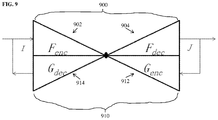
- FIG. 9 illustrates a deep image-to-image dual inverse network according to an embodiment of the present invention.
- the deep image-to-image dual inverse network includes a first DI2IN F 900 and a second DI2IN G 910 .
- the first DI2IN F 900 inputs a medical image I and outputs an output image J providing the result of a target medical image analysis task.
- the first DI2IN F 900 includes an encoder F enc 902 that converts the input medical image I to a high-level feature representation (feature map) and a decoder F dec 904 that converts the feature map output by the encoder F enc 902 to the output image J.
- the second DI2IN G 910 is an inverse network of the first DI2IN F 900 .
- the second DI2IN G 910 inputs image J and outputs image I.
- the second DI2IN G 910 includes an encoder G enc 912 that converts image J to a high-level feature representation (feature map) and a decoder G dec 914 that converts the feature map output by the encoder G enc 912 to reproduce image I.
- the task in training is to learn network parameters (weights) for F enc 902 , F dec 904 , G enc 912 , and G dec 914 that yield the solution that minimizes the following cost function:
- the first term is a loss function L 1 that calculates an error between the ground truth output image J n and the output image generated by the first DI2IN F 900 over the set of training samples.
- the second term of the cost function is a loss function L 2 that calculates an error between the original input image I and a reproduced input image generated by the second DI2IN G 910 from the ground truth output image J n over the set of training samples.
- the third term of the cost function incorporates the bridging constraint into the learning framework.
- the third term of the cost function is a loss function L e that calculates an error between the feature representation of I n generated by the encoder F enc 902 of the first DI2IN 900 and the feature representation of J n generated by the encoder G enc 912 of the second DI2IN 910 over the set of training samples.
- the minimization of the cost function of Equation (26) is achieved by iteratively alternating the following two steps until the parameters (weights) of F enc 902 , F dec 904 , G enc 912 , and G dec 914 converge (or until a preset maximum number of training iterations is reached:
- FIG. 10 illustrates a method for training a deep image-to-image network for performing a medical image analysis task in a deep image-to-image dual inverse network according to an embodiment of the present invention.
- training samples are received and/or generated.
- Each training pair includes a ground truth input medical image I n (or multiple input medical images, e.g., if the target medical image analysis task is registration) and a corresponding ground truth output image I n that provides the results of the target medical image analysis task for the input medical image I n .
- the DI2IN framework can be used to formulate many different medical image analysis problems.
- an output image In order to use the DI2IN framework to perform a particular medical image analysis task, an output image must be defined that provides the result of that medical image analysis task.
- the output image can be an image with a Gaussian-like blob surrounding each landmark.
- the output image can be a binary mask with pixels (or voxels) equal to 1 within a bounding box surrounding the target anatomical object and equal 0 at all other pixel locations.
- the output image can be a mask image whose value is 1 inside the segmented object boundary and 0 outside the segmented object boundary.
- the output image can be a deformation field.
- the output image is a denoised image.
- the input image is a medical image of one imaging modality and the output image is a synthesized medical image of a different imaging modality.
- the ground truth input images are medical images acquired using any type of medical imaging modality, such as computed tomography (CT), magnetic resonance (MR), DynaCT, ultrasound, x-ray, positron emission tomography (PET), etc., depending on the target medical image analysis task for which the DAN is to be trained.
- the ground truth input images can be received by loading a number of previously stored medical images from a database of medical images.
- the ground truth output images corresponding to the ground truth input images may be existing images that are stored in a database.
- the ground truth output images are received by loading the previously stored ground truth output image corresponding to each ground truth input image.
- ground truth output images can be generated automatically or semi-automatically from the received ground truth input images by converting manual annotations or existing results of the target medical image analysis task to the output images defined for the target medical image analysis task.
- Steps 1004 - 1008 of the FIG. 10 iteratively update weights of a first DI2IN (F network) that generates a predicted output image from each ground truth input image and a second DI2IN (G network) that is an inverse of the first DI2IN and generates a predicted input image from each ground truth output image to minimize a cost function.
- the weights of the first and second DI2INs are iteratively updated to optimize the cost function of Equation (26).
- the weights of the encoder F enc and the decoder F dec of the F network and the encoder G enc and the decoder G dec of the G network can be initialized using randomized weights, weights from other deep image-to-image networks trained for other medical image analysis tasks, or any other default initial values. It is to be understood that, although step 1004 is performed before step 1006 in the method of FIG. 10 , the order of these steps can be reversed.
- weights of the F network are learned to minimize the cost function.
- the weights of the encoder F enc and the decoder F dec of the F network are adjusted to minimize the loss due to the error between the ground truth output images and the predicted output images generated by the F network and the loss due to error between the feature representations of the ground input images generated by the encoder F enc of the F network and the feature representations of the ground truth output images generated by the encoder G enc of the G network over the set of training samples.
- weights of the G network are learned to minimize the cost function.
- the weights of the encoder G enc and the decoder G dec of the G network are adjusted to minimize the loss due to the error between the ground truth input images and the predicted input images generated by the G network and the loss due to error between the feature representations of the ground input images generated by the encoder F enc of the F network and the feature representations of the ground truth output images generated by the encoder G enc of the G network over the set of training samples.
- step 1008 it is determined whether a stop condition has been reached. If the stop condition has not yet been reached, the method returns to step 1004 . If the stop condition has been reached, the method proceeds to step 1010 .
- the stop condition is convergence of the weights of the F network and the G network. In this case, steps 1004 and 1006 are repeated until the weights of the F network and the G network converge. The stop condition could also be met when a predetermined maximum number of iterations has been reached.
- the trained F network (i.e., the first DI2IN) is stored in a memory or storage of a computer system and then used in the inference stage to generate an output image providing a result of the target medical image analysis task for each newly received medical image input to the trained F network.
- the trained G network can be stored in a memory or storage of a computer system as well.
- the trained G network may be used in inference to perform an inverse task to the target medical image analysis task.
- the trained G network can be used to synthesize a medical image of the first modality from an input medical image of the second modality.
- a medical image a patient is received.
- the medical image can be a 2D or 3D medical image acquired using any type of medical imaging modality, such as CT, MR, DynaCT, ultrasound, PET, etc.
- the input medical image may be a set of medical images.
- the input medical image may be received directly from an image acquisition device used to acquire the input medical image, such as a CT scanner, MR scanner, etc.
- the input medical image may be received by loading a previously acquired medical image from a storage or memory of a computer system or receiving a medical image that has been transmitted from a remote computer system.
- an output image that provides a result of a medical image analysis task is generated from the input image using the DI2IN trained to perform the medical image analysis task in the deep image-to-image dual inverse network.
- the trained DI2IN includes a trained encoder network that coverts the input medical image to a high-level feature representation and a decoder network that generates the output image providing the result of the target image analysis task from the feature representation generated by the encoder network.
- the type of output image generated by the trained DI2IN depends on the target medical image task. For example, an image with a Gaussian-like blob surrounding detected landmarks can be generated to provide the results of a landmark detection task.
- a mask image can be generated to provide the results of an anatomical object detection or segmentation task.
- a denoised medical image can be generated to provide the result of an image denoising task.
- a synthesized target domain medical image may be generated based on an input source domain medical image to provide the result on a cross-domain image synthesis task.
- a deformation field may be generated to provide the result for an image registration task between a pair of input medical images.
- the generated output image which provides the result of the target medical image analysis task for the input image, is output.
- the generated output image can be output by displaying the generated output image on a display device of a computer system.
- the generated output image can also be output by storing the generated output image on a memory or storage of a computer system or by transmitting the generated output image to a remote computer system.
- Computer 1102 contains a processor 1104 , which controls the overall operation of the computer 1102 by executing computer program instructions which define such operation.
- the computer program instructions may be stored in a storage device 1112 (e.g., magnetic disk) and loaded into memory 1110 when execution of the computer program instructions is desired.
- An image acquisition device 1120 such as an MRI scanner, can be connected to the computer 1102 to input image data to the computer 1102 . It is possible to implement the image acquisition device 1120 and the computer 1102 as one device. It is also possible that the image acquisition device 1120 and the computer 1102 communicate wirelessly through a network. In a possible embodiment, the computer 1102 can be located remotely with respect to the image acquisition device 1120 and the method steps described herein can be performed as part of a server or cloud based service. In this case, the method steps may be performed on a single computer or distributed between multiple networked computers.
- the computer 1102 also includes one or more network interfaces 1106 for communicating with other devices via a network.
- the computer 1102 also includes other input/output devices 808 that enable user interaction with the computer 1102 (e.g., display, keyboard, mouse, speakers, buttons, etc.).
- Such input/output devices 1108 may be used in conjunction with a set of computer programs as an annotation tool to annotate images/volumes received from the image acquisition device 1120 .
- FIG. 11 is a high level representation of some of the components of such a computer for illustrative purposes.
Abstract
Description
minθ C(θ|I)=−log(L(θ|I))−log(prior(θ|I)), (1)
where L(θ|I) is the likelihood function and prior(θ|I) is the prior probability that is also conditioned on I. Taking segmentation for example, the model θ is represented by a mask image θ=M(x)={m(x)}. With proper assumptions, the cost function is reduced to:
minM C(M|I)=ΣU(m(x)|I)+ΣV(m(x),m(y)|I), (2)
where U(m(x)|I) is the unary pixel-wise likelihood function and V(m(x),m(y)|I) is a pairwise function conditioned on the image I and based on a neighborhood graph.
minαmaxβ E I˜p(I)[log(D β(I))]+E z˜p(z)[log(1−D β(J=G α(z)))], (3)
where α and β are the parameters (weights) of the
minαmaxβ E I,θ˜p(I,θ)[(D β(θ|I))]+E I,θ˜p(I,θ)[log(1−D β(π=E α(I)|I))], (4)
where α and β are the parameters (weights) of the
minαmaxβ E I,θ˜p(I,θ)[C γ(θ,π=E α(I)|I)]+E I,θ˜p(I,θ)[log(D β(θ|I))]+E I,θ˜p(Iθ)[log(1−D β(π=E α(I)|I))]. (5)
In the embodiment described herein using the minimax objective function in Equation (6), the parameters γ of the
-
-
Step 1—With the parameters α of theestimator E α 400 fixed, solve the following maximization task for the parameters β of the discriminator Dβ 402:
-
-
- The discriminator Dβ 402 calculates a probability that a given image is a real image. Accordingly, in this maximization task, parameters β of the discriminator Dβ 402 are learned that increase/maximize the probability scores calculated for the real ground truth models θn by the Dβ 402 and decrease/minimize the probability scores calculated for the estimated models πn=Eα(In) by the discriminator Dβ 402 over the set of training samples. Since, as described above, a deep neural network is used to model the discriminator Dβ 402, this maximization task can be performed using a backpropagation step implemented based on a minibatch of training pairs.
- Step 2—With the β of the discriminator Dβ 402 fixed, solve the following minimization task for the parameters α of the estimator Eα 400:
-
- It is practically found that, rather than training the
estimator E α 400 to minimize log (1−Dβ(π)), training theestimator E α 400 to maximize log (Dβ(π)) leads to better gradient signals early in learning, even though both objective functions yield the same fixed point. Accordingly, in an advantageous implementation, the parameters α of theestimator E α 400 can be learned in step 2 using the following minimization problem:
- It is practically found that, rather than training the
-
- In this minimization problem, parameters a of the
estimator E α 400 are learned that minimize/decrease the error between the estimated models πn=Eα(In) and the ground truth models θn and maximize/increase the probability scores calculated for the estimated models πn=Eα(In) by the discriminator Dβ 402 over the set of training samples. Since, as described above, a deep neural network is used to model theestimator E α 400, this minimization task can be performed using a backpropagation step implemented based on a minibatch of training pairs.
- In this minimization problem, parameters a of the
J=F dec(F enc(I)). (10)
The encoder Fenc 702 of the
J=F(I); (11)
I=G(J). (12)
The use of the DIN introduces the following identify constraints that can be used to induce better learning:
I=G(F(I)); (13)
J=F(G(J)). (14)
In addition, the DIN learning simultaneously solves to problems within one learning framework at the cost of more computation.
J=F dec(F enc(I)); (15)
I=G dec(G enc(J)). (16)
For the deep image-to-image dual inverse network, the identity constraints now become:
G dec(G enc(F dec(F enc(I))))=I; (17)
F dec(F enc(G dec(G enc(J))))=J. (18)
According to an advantageous embodiment of the present invention, an additional constraint, referring herein as the “bridging constraint”, is introduced:
F enc(I)=G enc(J); (19)
This bridging constraint, when enforced during training, essentially brings the feature representations generated from I (by Fenc 902) and J (by Genc 912) together to the same “bridging” feature representation.
G dec(F enc(I))=I; (20)
F dec(G enc(J))=J. (21)
This can be verified as:
G dec(F enc(I))=G dec(G enc(I))=I; (22)
F dec(G enc(J))=F dec(F enc(I))=J. (23)
Further, with the newly introduced bridging constraint of Equation (19) enforced, the identity constraints in Equations (17) and (18) hold automatically. This can be verified as:
G dec(G enc(F dec(F enc(I))))=G dec(G enc(F dec(G enc(J))))=G dec(G enc(J))=I; (24)
F dec(F enc(G dec(G enc(I))))=F dec(F enc(G dec(F enc(I))))=F dec(F enc(I))=J. (25)
Accordingly, by enforcing the bridging constraint, the identity constraints are automatically satisfied as well. Thus, in an advantageous implementation, the training utilizes the bridging constraint and incorporates the bridging constraint as part of the learning criteria for learning the weights of the
in which L1, L2, and L3 are corresponding loss functions. In the cost function of Equation (26), the first term is a loss function L1 that calculates an error between the ground truth output image Jn and the output image generated by the
-
-
Step 1—WithG enc 912, andG dec 914 fixed, solve the following minimization task forF enc 902 and Fdec 904:
-
-
- In this step, parameters (weights) are learned for the
encoder F enc 902 anddecoder F dec 904 of thefirst DI2IN 900 to minimize the loss due to the error between the ground truth output image and the output image generated by thefirst DI2IN 900 and the loss due to error between the feature representation of the input image generated by theencoder F enc 902 of thefirst DI2IN 900 and the feature representation of the ground truth output image generated by theencoder G enc 912 of thesecond DI2IN 910 over the set of training samples. This minimization task can be performed using a backpropagation step implemented based on a minibatch of training pairs. - Step 2—With
F enc 902, andF dec 904 fixed, solve the following minimization task forG enc 912 and Gdec 914:
- In this step, parameters (weights) are learned for the
-
- In this step, parameters (weights) are learned for the
encoder G enc 912 anddecoder G dec 914 of thesecond DI2IN 910 to minimize the loss due to the error between the original input image and the reproduced input image generated by thesecond DI2IN 910 and the loss due to error between the feature representation of the input image generated by the encoder Fen, 902 of thefirst DI2IN 900 and the feature representation of the ground truth output image generated by theencoder G enc 912 of thesecond DI2IN 910 over the set of training samples. This minimization task can be performed using a backpropagation step implemented based on a minibatch of training pairs.
- In this step, parameters (weights) are learned for the
Claims (15)
Priority Applications (2)
| Application Number | Priority Date | Filing Date | Title |
|---|---|---|---|
| US15/868,062 US10636141B2 (en) | 2017-02-09 | 2018-01-11 | Adversarial and dual inverse deep learning networks for medical image analysis |
| US16/822,101 US11055847B2 (en) | 2017-02-09 | 2020-03-18 | Adversarial and dual inverse deep learning networks for medical image analysis |
Applications Claiming Priority (2)
| Application Number | Priority Date | Filing Date | Title |
|---|---|---|---|
| US201762457013P | 2017-02-09 | 2017-02-09 | |
| US15/868,062 US10636141B2 (en) | 2017-02-09 | 2018-01-11 | Adversarial and dual inverse deep learning networks for medical image analysis |
Related Child Applications (1)
| Application Number | Title | Priority Date | Filing Date |
|---|---|---|---|
| US16/822,101 Division US11055847B2 (en) | 2017-02-09 | 2020-03-18 | Adversarial and dual inverse deep learning networks for medical image analysis |
Publications (2)
| Publication Number | Publication Date |
|---|---|
| US20180225823A1 US20180225823A1 (en) | 2018-08-09 |
| US10636141B2 true US10636141B2 (en) | 2020-04-28 |
Family
ID=63037789
Family Applications (2)
| Application Number | Title | Priority Date | Filing Date |
|---|---|---|---|
| US15/868,062 Active 2038-04-14 US10636141B2 (en) | 2017-02-09 | 2018-01-11 | Adversarial and dual inverse deep learning networks for medical image analysis |
| US16/822,101 Active US11055847B2 (en) | 2017-02-09 | 2020-03-18 | Adversarial and dual inverse deep learning networks for medical image analysis |
Family Applications After (1)
| Application Number | Title | Priority Date | Filing Date |
|---|---|---|---|
| US16/822,101 Active US11055847B2 (en) | 2017-02-09 | 2020-03-18 | Adversarial and dual inverse deep learning networks for medical image analysis |
Country Status (1)
| Country | Link |
|---|---|
| US (2) | US10636141B2 (en) |
Cited By (2)
| Publication number | Priority date | Publication date | Assignee | Title |
|---|---|---|---|---|
| US11304619B2 (en) * | 2018-07-18 | 2022-04-19 | Siemens Healthcare Gmbh | Generating setting parameters for an MRI sequence |
| US11748887B2 (en) * | 2019-04-08 | 2023-09-05 | Nvidia Corporation | Segmentation using an unsupervised neural network training technique |
Families Citing this family (69)
| Publication number | Priority date | Publication date | Assignee | Title |
|---|---|---|---|---|
| US10115194B2 (en) * | 2015-04-06 | 2018-10-30 | IDx, LLC | Systems and methods for feature detection in retinal images |
| US11273553B2 (en) * | 2017-06-05 | 2022-03-15 | Autodesk, Inc. | Adapting simulation data to real-world conditions encountered by physical processes |
| US11250329B2 (en) | 2017-10-26 | 2022-02-15 | Nvidia Corporation | Progressive modification of generative adversarial neural networks |
| US11263525B2 (en) | 2017-10-26 | 2022-03-01 | Nvidia Corporation | Progressive modification of neural networks |
| JP2019079374A (en) * | 2017-10-26 | 2019-05-23 | 株式会社Preferred Networks | Image processing system, image processing method, and image processing program |
| US10482600B2 (en) * | 2018-01-16 | 2019-11-19 | Siemens Healthcare Gmbh | Cross-domain image analysis and cross-domain image synthesis using deep image-to-image networks and adversarial networks |
| US10910099B2 (en) * | 2018-02-20 | 2021-02-02 | Siemens Healthcare Gmbh | Segmentation, landmark detection and view classification using multi-task learning |
| US10956785B2 (en) | 2018-04-27 | 2021-03-23 | Arizona Board Of Regents On Behalf Of Arizona State University | Methods, systems, and media for selecting candidates for annotation for use in training classifiers |
| CN109166126B (en) * | 2018-08-13 | 2022-02-18 | 苏州比格威医疗科技有限公司 | Method for segmenting paint cracks on ICGA image based on condition generation type countermeasure network |
| CN109345575B (en) * | 2018-09-17 | 2021-01-19 | 中国科学院深圳先进技术研究院 | Image registration method and device based on deep learning |
| CN110941188A (en) * | 2018-09-25 | 2020-03-31 | 珠海格力电器股份有限公司 | Intelligent household control method and device |
| CN109559358B (en) * | 2018-10-22 | 2023-07-04 | 天津大学 | Image sample up-sampling method based on convolution self-coding |
| CN109583474B (en) * | 2018-11-01 | 2022-07-05 | 华中科技大学 | Training sample generation method for industrial big data processing |
| US11244453B2 (en) | 2018-11-02 | 2022-02-08 | Siemens Healthcare Gmbh | Determining malignancy of pulmonary nodules using deep learning |
| EP3657433B1 (en) * | 2018-11-22 | 2022-10-19 | Siemens Healthcare GmbH | Medical image data |
| EP3660741B1 (en) | 2018-11-29 | 2022-05-04 | Koninklijke Philips N.V. | Feature identification in medical imaging |
| US11158069B2 (en) * | 2018-12-11 | 2021-10-26 | Siemens Healthcare Gmbh | Unsupervised deformable registration for multi-modal images |
| WO2020120238A1 (en) * | 2018-12-12 | 2020-06-18 | Koninklijke Philips N.V. | System and method for providing stroke lesion segmentation using conditional generative adversarial networks |
| CN111325671B (en) * | 2018-12-13 | 2023-07-04 | 北京嘀嘀无限科技发展有限公司 | Network training method and device, image processing method and electronic equipment |
| TWI705340B (en) | 2018-12-13 | 2020-09-21 | 財團法人工業技術研究院 | Training method for phase image generator and training method of phase image classifier |
| WO2020127031A1 (en) * | 2018-12-18 | 2020-06-25 | Agfa Nv | Method of decomposing a radiographic image into sub-images of different types |
| CN109635774B (en) * | 2018-12-21 | 2022-09-13 | 中山大学 | Face synthesis method based on generation of confrontation network |
| CN111383741B (en) * | 2018-12-27 | 2022-05-10 | 深圳先进技术研究院 | Method, device and equipment for establishing medical imaging model and storage medium |
| CN109948658B (en) * | 2019-02-25 | 2021-06-15 | 浙江工业大学 | Feature diagram attention mechanism-oriented anti-attack defense method and application |
| CN110070935B (en) * | 2019-03-20 | 2021-04-30 | 中国科学院自动化研究所 | Medical image synthesis method, classification method and device based on antagonistic neural network |
| WO2020198854A1 (en) * | 2019-03-29 | 2020-10-08 | Polyvalor, Limited Partnership | Method and system for producing medical images |
| WO2020205249A1 (en) * | 2019-03-29 | 2020-10-08 | Tornier, Inc. | Pre-morbid characterization of anatomical object using statistical shape modeling (ssm) |
| CN110033033B (en) * | 2019-04-01 | 2023-04-18 | 南京谱数光电科技有限公司 | Generator model training method based on CGANs |
| CN110021052B (en) * | 2019-04-11 | 2023-05-30 | 北京百度网讯科技有限公司 | Method and apparatus for generating fundus image generation model |
| KR102034248B1 (en) * | 2019-04-19 | 2019-10-18 | 주식회사 루닛 | Method for detecting anomaly using generative adversarial networks, apparatus and system thereof |
| KR102062157B1 (en) * | 2019-04-29 | 2020-01-03 | 오케스트로 주식회사 | Vitual machine placement method and virtual machine placement device implementing the same |
| CN110197716B (en) * | 2019-05-20 | 2022-05-20 | 广东技术师范大学 | Medical image processing method and device and computer readable storage medium |
| CN110276728B (en) * | 2019-05-28 | 2022-08-05 | 河海大学 | Human face video enhancement method based on residual error generation countermeasure network |
| CN110175655B (en) * | 2019-06-03 | 2020-12-25 | 中国科学技术大学 | Data identification method and device, storage medium and electronic equipment |
| CN110245598B (en) * | 2019-06-06 | 2020-10-09 | 北京瑞莱智慧科技有限公司 | Countermeasure sample generation method, apparatus, medium, and computing device |
| CN110222502A (en) * | 2019-06-10 | 2019-09-10 | 北京计算机技术及应用研究所 | A kind of dual training method of injection randomization |
| US10990855B2 (en) * | 2019-06-13 | 2021-04-27 | Baidu Usa Llc | Detecting adversarial samples by a vision based perception system |
| CN110458770A (en) * | 2019-07-26 | 2019-11-15 | 复旦大学附属中山医院 | A kind of medical image brightness homogenization bearing calibration |
| CN110597628B (en) * | 2019-08-29 | 2023-10-10 | 腾讯科技(深圳)有限公司 | Model distribution method, device, computer readable medium and electronic equipment |
| CN110717522A (en) * | 2019-09-18 | 2020-01-21 | 平安科技(深圳)有限公司 | Countermeasure defense method of image classification network and related device |
| CN110851835A (en) * | 2019-09-23 | 2020-02-28 | 平安科技(深圳)有限公司 | Image model detection method and device, electronic equipment and storage medium |
| US11538576B2 (en) | 2019-10-15 | 2022-12-27 | International Business Machines Corporation | Illustrative medical imaging for functional prognosis estimation |
| CN110930318B (en) * | 2019-10-31 | 2023-04-18 | 中山大学 | Low-dose CT image repairing and denoising method |
| US10762629B1 (en) | 2019-11-14 | 2020-09-01 | SegAI LLC | Segmenting medical images |
| US11423544B1 (en) | 2019-11-14 | 2022-08-23 | Seg AI LLC | Segmenting medical images |
| CN110889836A (en) * | 2019-11-22 | 2020-03-17 | 中国人民解放军第四军医大学 | Image data analysis method and device, terminal equipment and storage medium |
| US11790492B1 (en) * | 2019-12-18 | 2023-10-17 | Thales Sa | Method of and system for customized image denoising with model interpretations |
| US11651220B2 (en) * | 2019-12-20 | 2023-05-16 | Robert Bosch Gmbh | Asymmetrical robustness for classification in adversarial environments |
| EP4094187A4 (en) * | 2020-01-23 | 2023-09-06 | Telefonaktiebolaget Lm Ericsson (Publ) | Method and apparatus for image classification |
| US11348243B2 (en) | 2020-01-24 | 2022-05-31 | GE Precision Healthcare LLC | Systems and methods for medical image style transfer using deep neural networks |
| EP4094223A1 (en) * | 2020-01-24 | 2022-11-30 | Genentech, Inc. | Weakly supervised lesion segmentation |
| US11710042B2 (en) * | 2020-02-05 | 2023-07-25 | Adobe Inc. | Shaping a neural network architecture utilizing learnable sampling layers |
| US11532086B2 (en) * | 2020-02-20 | 2022-12-20 | International Business Machines Corporation | Systems and methods to facilitate determination of interaction between medications and the brain using a brain measure and a brain model |
| US11663481B2 (en) | 2020-02-24 | 2023-05-30 | Adobe Inc. | Neural network architecture pruning |
| CN111462264B (en) * | 2020-03-17 | 2023-06-06 | 中国科学院深圳先进技术研究院 | Medical image reconstruction method, medical image reconstruction network training method and device |
| CN111626917B (en) * | 2020-04-13 | 2024-02-20 | 上海交通大学 | Bidirectional image conversion system and method based on deep learning |
| US11699514B2 (en) | 2020-05-27 | 2023-07-11 | International Business Machines Corporation | Predictive dual machine translation |
| CN112102294B (en) * | 2020-09-16 | 2024-03-01 | 推想医疗科技股份有限公司 | Training method and device for generating countermeasure network, and image registration method and device |
| CN112150378B (en) * | 2020-09-18 | 2022-06-24 | 浙江明峰智能医疗科技有限公司 | Low-dose whole-body PET image enhancement method based on self-inverse convolution generation countermeasure network |
| JP2022077991A (en) * | 2020-11-12 | 2022-05-24 | ザ ユニバーシティ コート オブ ザ ユニバーシティ オブ エジンバラ | Medical image processing apparatus, medical image processing method, medical image processing program, model training apparatus, and training method |
| CN112381788B (en) * | 2020-11-13 | 2022-11-22 | 北京工商大学 | Part surface defect increment detection method based on double-branch matching network |
| US11762951B2 (en) * | 2020-11-18 | 2023-09-19 | Adobe Inc. | Generative image congealing |
| KR102510221B1 (en) * | 2020-12-24 | 2023-03-15 | 연세대학교 산학협력단 | A method of bone fracture prediction and an apparatus thereof |
| US20220301156A1 (en) * | 2021-03-16 | 2022-09-22 | Shenzhen Keya Medical Technology Corporation | Method and system for annotation efficient learning for medical image analysis |
| CN113012204B (en) * | 2021-04-09 | 2024-01-16 | 福建自贸试验区厦门片区Manteia数据科技有限公司 | Registration method, registration device, storage medium and processor for multi-mode image |
| EP4092621A1 (en) | 2021-05-21 | 2022-11-23 | Siemens Healthcare GmbH | Technique for assigning a perfusion metric to dce mr images |
| CN113269812A (en) * | 2021-05-25 | 2021-08-17 | 平安科技(深圳)有限公司 | Image prediction model training and application method, device, equipment and storage medium |
| CN113539408B (en) * | 2021-08-31 | 2022-02-25 | 北京字节跳动网络技术有限公司 | Medical report generation method, training device and training equipment of model |
| CN114005168A (en) * | 2021-12-31 | 2022-02-01 | 北京瑞莱智慧科技有限公司 | Physical world confrontation sample generation method and device, electronic equipment and storage medium |
Citations (14)
| Publication number | Priority date | Publication date | Assignee | Title |
|---|---|---|---|---|
| US20150170002A1 (en) | 2013-05-31 | 2015-06-18 | Google Inc. | Object detection using deep neural networks |
| US20150238148A1 (en) | 2013-10-17 | 2015-08-27 | Siemens Aktiengesellschaft | Method and system for anatomical object detection using marginal space deep neural networks |
| US20160063359A1 (en) | 2014-08-29 | 2016-03-03 | Google Inc. | Processing images using deep neural networks |
| US20160093048A1 (en) | 2014-09-25 | 2016-03-31 | Siemens Healthcare Gmbh | Deep similarity learning for multimodal medical images |
| US20160140424A1 (en) | 2014-11-13 | 2016-05-19 | Nec Laboratories America, Inc. | Object-centric Fine-grained Image Classification |
| US9373059B1 (en) | 2014-05-05 | 2016-06-21 | Atomwise Inc. | Systems and methods for applying a convolutional network to spatial data |
| US20160180195A1 (en) | 2013-09-06 | 2016-06-23 | Toyota Jidosha Kabushiki Kaisha | Augmenting Layer-Based Object Detection With Deep Convolutional Neural Networks |
| US20160174902A1 (en) | 2013-10-17 | 2016-06-23 | Siemens Aktiengesellschaft | Method and System for Anatomical Object Detection Using Marginal Space Deep Neural Networks |
| US20160210749A1 (en) | 2015-01-21 | 2016-07-21 | Siemens Aktiengesellschaft | Method and system for cross-domain synthesis of medical images using contextual deep network |
| US20160328643A1 (en) | 2015-05-07 | 2016-11-10 | Siemens Aktiengesellschaft | Method and System for Approximating Deep Neural Networks for Anatomical Object Detection |
| US20170200067A1 (en) | 2016-01-08 | 2017-07-13 | Siemens Healthcare Gmbh | Deep Image-to-Image Network Learning for Medical Image Analysis |
| US20180075581A1 (en) * | 2016-09-15 | 2018-03-15 | Twitter, Inc. | Super resolution using a generative adversarial network |
| US20180174049A1 (en) * | 2016-12-19 | 2018-06-21 | Siemens Healthcare Gmbh | Method and computer for determination of a training function for generating annotated training images |
| US20180211164A1 (en) * | 2017-01-23 | 2018-07-26 | Fotonation Limited | Method of training a neural network |
Family Cites Families (2)
| Publication number | Priority date | Publication date | Assignee | Title |
|---|---|---|---|---|
| US9971966B2 (en) * | 2016-02-26 | 2018-05-15 | Google Llc | Processing cell images using neural networks |
| US10373312B2 (en) * | 2016-11-06 | 2019-08-06 | International Business Machines Corporation | Automated skin lesion segmentation using deep side layers |
-
2018
- 2018-01-11 US US15/868,062 patent/US10636141B2/en active Active
-
2020
- 2020-03-18 US US16/822,101 patent/US11055847B2/en active Active
Patent Citations (18)
| Publication number | Priority date | Publication date | Assignee | Title |
|---|---|---|---|---|
| US9275308B2 (en) | 2013-05-31 | 2016-03-01 | Google Inc. | Object detection using deep neural networks |
| US20150170002A1 (en) | 2013-05-31 | 2015-06-18 | Google Inc. | Object detection using deep neural networks |
| US20160180195A1 (en) | 2013-09-06 | 2016-06-23 | Toyota Jidosha Kabushiki Kaisha | Augmenting Layer-Based Object Detection With Deep Convolutional Neural Networks |
| US20160174902A1 (en) | 2013-10-17 | 2016-06-23 | Siemens Aktiengesellschaft | Method and System for Anatomical Object Detection Using Marginal Space Deep Neural Networks |
| US20150238148A1 (en) | 2013-10-17 | 2015-08-27 | Siemens Aktiengesellschaft | Method and system for anatomical object detection using marginal space deep neural networks |
| US9373059B1 (en) | 2014-05-05 | 2016-06-21 | Atomwise Inc. | Systems and methods for applying a convolutional network to spatial data |
| US20160063359A1 (en) | 2014-08-29 | 2016-03-03 | Google Inc. | Processing images using deep neural networks |
| US20170316286A1 (en) | 2014-08-29 | 2017-11-02 | Google Inc. | Processing images using deep neural networks |
| US20160093048A1 (en) | 2014-09-25 | 2016-03-31 | Siemens Healthcare Gmbh | Deep similarity learning for multimodal medical images |
| US20160140424A1 (en) | 2014-11-13 | 2016-05-19 | Nec Laboratories America, Inc. | Object-centric Fine-grained Image Classification |
| US20160210749A1 (en) | 2015-01-21 | 2016-07-21 | Siemens Aktiengesellschaft | Method and system for cross-domain synthesis of medical images using contextual deep network |
| US20160328643A1 (en) | 2015-05-07 | 2016-11-10 | Siemens Aktiengesellschaft | Method and System for Approximating Deep Neural Networks for Anatomical Object Detection |
| US20170200067A1 (en) | 2016-01-08 | 2017-07-13 | Siemens Healthcare Gmbh | Deep Image-to-Image Network Learning for Medical Image Analysis |
| US9760807B2 (en) | 2016-01-08 | 2017-09-12 | Siemens Healthcare Gmbh | Deep image-to-image network learning for medical image analysis |
| US20170277981A1 (en) | 2016-01-08 | 2017-09-28 | Siemens Healthcare Gmbh | Deep Image-to-Image Network Learning for Medical Image Analysis |
| US20180075581A1 (en) * | 2016-09-15 | 2018-03-15 | Twitter, Inc. | Super resolution using a generative adversarial network |
| US20180174049A1 (en) * | 2016-12-19 | 2018-06-21 | Siemens Healthcare Gmbh | Method and computer for determination of a training function for generating annotated training images |
| US20180211164A1 (en) * | 2017-01-23 | 2018-07-26 | Fotonation Limited | Method of training a neural network |
Non-Patent Citations (4)
| Title |
|---|
| Goodfellow et al., "Generative Adversarial Nets"; Universite of Montreal, Montreal, QC; Jun. 10, 2014; pp. 1-9. |
| Liu, Ming-Yu, and Oncel Tuzel. "Coupled generative adversarial networks." Advances in neural information processing systems. 2016. (Year: 2016). * |
| Makhzani, Alireza, et al. "Adversarial autoencoders." arXiv preprint arXiv:1511.05644 (2015) (Year: 2015). * |
| Springenberg, Jost Tobias. "Unsupervised and semi-supervised learning with categorical generative adversarial networks." arXiv preprint arXiv:1511.06390 (2015). (Year: 2015). * |
Cited By (2)
| Publication number | Priority date | Publication date | Assignee | Title |
|---|---|---|---|---|
| US11304619B2 (en) * | 2018-07-18 | 2022-04-19 | Siemens Healthcare Gmbh | Generating setting parameters for an MRI sequence |
| US11748887B2 (en) * | 2019-04-08 | 2023-09-05 | Nvidia Corporation | Segmentation using an unsupervised neural network training technique |
Also Published As
| Publication number | Publication date |
|---|---|
| US20180225823A1 (en) | 2018-08-09 |
| US11055847B2 (en) | 2021-07-06 |
| US20200219259A1 (en) | 2020-07-09 |
Similar Documents
| Publication | Publication Date | Title |
|---|---|---|
| US11055847B2 (en) | Adversarial and dual inverse deep learning networks for medical image analysis | |
| US10482600B2 (en) | Cross-domain image analysis and cross-domain image synthesis using deep image-to-image networks and adversarial networks | |
| US10885399B2 (en) | Deep image-to-image network learning for medical image analysis | |
| US10600185B2 (en) | Automatic liver segmentation using adversarial image-to-image network | |
| US11593943B2 (en) | RECIST assessment of tumour progression | |
| US10489907B2 (en) | Artifact identification and/or correction for medical imaging | |
| US9710730B2 (en) | Image registration | |
| US11328412B2 (en) | Hierarchical learning of weights of a neural network for performing multiple analyses | |
| CN110570426B (en) | Image co-registration and segmentation using deep learning | |
| US20160210749A1 (en) | Method and system for cross-domain synthesis of medical images using contextual deep network | |
| US8867802B2 (en) | Automatic organ localization | |
| US9299145B2 (en) | Image segmentation techniques | |
| US20210233244A1 (en) | System and method for image segmentation using a joint deep learning model | |
| US11508061B2 (en) | Medical image segmentation with uncertainty estimation | |
| US10275909B2 (en) | Systems and methods for an integrated system for visualizing, simulating, modifying and 3D printing 3D objects | |
| EP3961561A1 (en) | Method for designing a module for image segmentation | |
| US20230154165A1 (en) | Image learning method, apparatus, program, and recording medium using generative adversarial network | |
| CN111563496A (en) | Continuous learning for automatic view planning for image acquisition | |
| US20220270256A1 (en) | Compensation of organ deformation for medical image registration | |
| US20230343438A1 (en) | Systems and methods for automatic image annotation | |
| US20230245329A1 (en) | Structured landmark detection via topology-adapting deep graph learning | |
| KR20240051159A (en) | Systems and methods for medical image conversion |
Legal Events
| Date | Code | Title | Description |
|---|---|---|---|
| FEPP | Fee payment procedure |
Free format text: ENTITY STATUS SET TO UNDISCOUNTED (ORIGINAL EVENT CODE: BIG.); ENTITY STATUS OF PATENT OWNER: LARGE ENTITY |
|
| AS | Assignment |
Owner name: SIEMENS MEDICAL SOLUTIONS USA, INC., PENNSYLVANIA Free format text: ASSIGNMENT OF ASSIGNORS INTEREST;ASSIGNORS:CHEN, MINGQING;XU, DAGUANG;XU, ZHOUBING;AND OTHERS;SIGNING DATES FROM 20180111 TO 20180112;REEL/FRAME:044625/0555 |
|
| AS | Assignment |
Owner name: SIEMENS HEALTHCARE GMBH, GERMANY Free format text: ASSIGNMENT OF ASSIGNORS INTEREST;ASSIGNOR:SIEMENS MEDICAL SOLUTIONS USA, INC.;REEL/FRAME:044655/0799 Effective date: 20180117 |
|
| STPP | Information on status: patent application and granting procedure in general |
Free format text: DOCKETED NEW CASE - READY FOR EXAMINATION |
|
| STPP | Information on status: patent application and granting procedure in general |
Free format text: NON FINAL ACTION MAILED |
|
| STPP | Information on status: patent application and granting procedure in general |
Free format text: RESPONSE TO NON-FINAL OFFICE ACTION ENTERED AND FORWARDED TO EXAMINER |
|
| STPP | Information on status: patent application and granting procedure in general |
Free format text: NON FINAL ACTION MAILED |
|
| STPP | Information on status: patent application and granting procedure in general |
Free format text: FINAL REJECTION MAILED |
|
| STPP | Information on status: patent application and granting procedure in general |
Free format text: NOTICE OF ALLOWANCE MAILED -- APPLICATION RECEIVED IN OFFICE OF PUBLICATIONS |
|
| STCF | Information on status: patent grant |
Free format text: PATENTED CASE |
|
| MAFP | Maintenance fee payment |
Free format text: PAYMENT OF MAINTENANCE FEE, 4TH YEAR, LARGE ENTITY (ORIGINAL EVENT CODE: M1551); ENTITY STATUS OF PATENT OWNER: LARGE ENTITY Year of fee payment: 4 |
|
| AS | Assignment |
Owner name: SIEMENS HEALTHINEERS AG, GERMANY Free format text: ASSIGNMENT OF ASSIGNORS INTEREST;ASSIGNOR:SIEMENS HEALTHCARE GMBH;REEL/FRAME:066267/0346 Effective date: 20231219 |