US10635976B2 - Machine learning system for estimating a temperature of an exhaust purification catalyst - Google Patents
Machine learning system for estimating a temperature of an exhaust purification catalyst Download PDFInfo
- Publication number
- US10635976B2 US10635976B2 US15/987,172 US201815987172A US10635976B2 US 10635976 B2 US10635976 B2 US 10635976B2 US 201815987172 A US201815987172 A US 201815987172A US 10635976 B2 US10635976 B2 US 10635976B2
- Authority
- US
- United States
- Prior art keywords
- engine
- purification catalyst
- exhaust purification
- temperature
- concentration
- Prior art date
- Legal status (The legal status is an assumption and is not a legal conclusion. Google has not performed a legal analysis and makes no representation as to the accuracy of the status listed.)
- Active, expires
Links
- 239000003054 catalyst Substances 0.000 title claims abstract description 263
- 238000000746 purification Methods 0.000 title claims abstract description 233
- 238000010801 machine learning Methods 0.000 title claims description 63
- 239000000446 fuel Substances 0.000 claims abstract description 112
- 238000013528 artificial neural network Methods 0.000 claims abstract description 101
- 238000012549 training Methods 0.000 claims abstract description 33
- 238000002485 combustion reaction Methods 0.000 claims description 28
- 239000007789 gas Substances 0.000 description 104
- 230000006870 function Effects 0.000 description 46
- 230000000875 corresponding effect Effects 0.000 description 14
- 238000003860 storage Methods 0.000 description 13
- 238000000034 method Methods 0.000 description 9
- QVGXLLKOCUKJST-UHFFFAOYSA-N atomic oxygen Chemical compound [O] QVGXLLKOCUKJST-UHFFFAOYSA-N 0.000 description 6
- 238000007254 oxidation reaction Methods 0.000 description 6
- 229910052760 oxygen Inorganic materials 0.000 description 6
- 239000001301 oxygen Substances 0.000 description 6
- 238000004422 calculation algorithm Methods 0.000 description 5
- 238000011478 gradient descent method Methods 0.000 description 5
- 238000004519 manufacturing process Methods 0.000 description 5
- 230000003213 activating effect Effects 0.000 description 4
- 238000004364 calculation method Methods 0.000 description 4
- 238000012545 processing Methods 0.000 description 4
- 238000010586 diagram Methods 0.000 description 3
- 230000000694 effects Effects 0.000 description 3
- 230000007423 decrease Effects 0.000 description 2
- 238000009826 distribution Methods 0.000 description 2
- 210000002569 neuron Anatomy 0.000 description 2
- 230000002123 temporal effect Effects 0.000 description 2
- 238000010200 validation analysis Methods 0.000 description 2
- UGFAIRIUMAVXCW-UHFFFAOYSA-N Carbon monoxide Chemical compound [O+]#[C-] UGFAIRIUMAVXCW-UHFFFAOYSA-N 0.000 description 1
- 230000004913 activation Effects 0.000 description 1
- 230000002457 bidirectional effect Effects 0.000 description 1
- 229910002091 carbon monoxide Inorganic materials 0.000 description 1
- 230000003197 catalytic effect Effects 0.000 description 1
- 238000001816 cooling Methods 0.000 description 1
- 230000002596 correlated effect Effects 0.000 description 1
- 238000002790 cross-validation Methods 0.000 description 1
- 238000001704 evaporation Methods 0.000 description 1
- 230000008020 evaporation Effects 0.000 description 1
- 238000002474 experimental method Methods 0.000 description 1
- -1 for example Substances 0.000 description 1
- 239000002828 fuel tank Substances 0.000 description 1
- 239000003502 gasoline Substances 0.000 description 1
- 229930195733 hydrocarbon Natural products 0.000 description 1
- 150000002430 hydrocarbons Chemical class 0.000 description 1
- 238000002347 injection Methods 0.000 description 1
- 239000007924 injection Substances 0.000 description 1
- 238000013021 overheating Methods 0.000 description 1
- 238000007637 random forest analysis Methods 0.000 description 1
- 238000012706 support-vector machine Methods 0.000 description 1
- 238000012360 testing method Methods 0.000 description 1
- 239000013598 vector Substances 0.000 description 1
Images


Classifications
-
- G—PHYSICS
- G06—COMPUTING; CALCULATING OR COUNTING
- G06N—COMPUTING ARRANGEMENTS BASED ON SPECIFIC COMPUTATIONAL MODELS
- G06N3/00—Computing arrangements based on biological models
- G06N3/02—Neural networks
- G06N3/08—Learning methods
-
- F—MECHANICAL ENGINEERING; LIGHTING; HEATING; WEAPONS; BLASTING
- F01—MACHINES OR ENGINES IN GENERAL; ENGINE PLANTS IN GENERAL; STEAM ENGINES
- F01N—GAS-FLOW SILENCERS OR EXHAUST APPARATUS FOR MACHINES OR ENGINES IN GENERAL; GAS-FLOW SILENCERS OR EXHAUST APPARATUS FOR INTERNAL COMBUSTION ENGINES
- F01N11/00—Monitoring or diagnostic devices for exhaust-gas treatment apparatus, e.g. for catalytic activity
- F01N11/002—Monitoring or diagnostic devices for exhaust-gas treatment apparatus, e.g. for catalytic activity the diagnostic devices measuring or estimating temperature or pressure in, or downstream of the exhaust apparatus
- F01N11/005—Monitoring or diagnostic devices for exhaust-gas treatment apparatus, e.g. for catalytic activity the diagnostic devices measuring or estimating temperature or pressure in, or downstream of the exhaust apparatus the temperature or pressure being estimated, e.g. by means of a theoretical model
-
- F—MECHANICAL ENGINEERING; LIGHTING; HEATING; WEAPONS; BLASTING
- F01—MACHINES OR ENGINES IN GENERAL; ENGINE PLANTS IN GENERAL; STEAM ENGINES
- F01N—GAS-FLOW SILENCERS OR EXHAUST APPARATUS FOR MACHINES OR ENGINES IN GENERAL; GAS-FLOW SILENCERS OR EXHAUST APPARATUS FOR INTERNAL COMBUSTION ENGINES
- F01N9/00—Electrical control of exhaust gas treating apparatus
-
- G—PHYSICS
- G06—COMPUTING; CALCULATING OR COUNTING
- G06N—COMPUTING ARRANGEMENTS BASED ON SPECIFIC COMPUTATIONAL MODELS
- G06N3/00—Computing arrangements based on biological models
- G06N3/02—Neural networks
- G06N3/04—Architecture, e.g. interconnection topology
-
- G—PHYSICS
- G06—COMPUTING; CALCULATING OR COUNTING
- G06N—COMPUTING ARRANGEMENTS BASED ON SPECIFIC COMPUTATIONAL MODELS
- G06N3/00—Computing arrangements based on biological models
- G06N3/02—Neural networks
- G06N3/08—Learning methods
- G06N3/084—Backpropagation, e.g. using gradient descent
-
- F—MECHANICAL ENGINEERING; LIGHTING; HEATING; WEAPONS; BLASTING
- F01—MACHINES OR ENGINES IN GENERAL; ENGINE PLANTS IN GENERAL; STEAM ENGINES
- F01N—GAS-FLOW SILENCERS OR EXHAUST APPARATUS FOR MACHINES OR ENGINES IN GENERAL; GAS-FLOW SILENCERS OR EXHAUST APPARATUS FOR INTERNAL COMBUSTION ENGINES
- F01N2560/00—Exhaust systems with means for detecting or measuring exhaust gas components or characteristics
- F01N2560/02—Exhaust systems with means for detecting or measuring exhaust gas components or characteristics the means being an exhaust gas sensor
- F01N2560/022—Exhaust systems with means for detecting or measuring exhaust gas components or characteristics the means being an exhaust gas sensor for measuring or detecting CO or CO2
-
- F—MECHANICAL ENGINEERING; LIGHTING; HEATING; WEAPONS; BLASTING
- F01—MACHINES OR ENGINES IN GENERAL; ENGINE PLANTS IN GENERAL; STEAM ENGINES
- F01N—GAS-FLOW SILENCERS OR EXHAUST APPARATUS FOR MACHINES OR ENGINES IN GENERAL; GAS-FLOW SILENCERS OR EXHAUST APPARATUS FOR INTERNAL COMBUSTION ENGINES
- F01N2560/00—Exhaust systems with means for detecting or measuring exhaust gas components or characteristics
- F01N2560/02—Exhaust systems with means for detecting or measuring exhaust gas components or characteristics the means being an exhaust gas sensor
- F01N2560/023—Exhaust systems with means for detecting or measuring exhaust gas components or characteristics the means being an exhaust gas sensor for measuring or detecting HC
-
- F—MECHANICAL ENGINEERING; LIGHTING; HEATING; WEAPONS; BLASTING
- F01—MACHINES OR ENGINES IN GENERAL; ENGINE PLANTS IN GENERAL; STEAM ENGINES
- F01N—GAS-FLOW SILENCERS OR EXHAUST APPARATUS FOR MACHINES OR ENGINES IN GENERAL; GAS-FLOW SILENCERS OR EXHAUST APPARATUS FOR INTERNAL COMBUSTION ENGINES
- F01N2560/00—Exhaust systems with means for detecting or measuring exhaust gas components or characteristics
- F01N2560/06—Exhaust systems with means for detecting or measuring exhaust gas components or characteristics the means being a temperature sensor
-
- F—MECHANICAL ENGINEERING; LIGHTING; HEATING; WEAPONS; BLASTING
- F01—MACHINES OR ENGINES IN GENERAL; ENGINE PLANTS IN GENERAL; STEAM ENGINES
- F01N—GAS-FLOW SILENCERS OR EXHAUST APPARATUS FOR MACHINES OR ENGINES IN GENERAL; GAS-FLOW SILENCERS OR EXHAUST APPARATUS FOR INTERNAL COMBUSTION ENGINES
- F01N2900/00—Details of electrical control or of the monitoring of the exhaust gas treating apparatus
- F01N2900/04—Methods of control or diagnosing
- F01N2900/0402—Methods of control or diagnosing using adaptive learning
-
- F—MECHANICAL ENGINEERING; LIGHTING; HEATING; WEAPONS; BLASTING
- F01—MACHINES OR ENGINES IN GENERAL; ENGINE PLANTS IN GENERAL; STEAM ENGINES
- F01N—GAS-FLOW SILENCERS OR EXHAUST APPARATUS FOR MACHINES OR ENGINES IN GENERAL; GAS-FLOW SILENCERS OR EXHAUST APPARATUS FOR INTERNAL COMBUSTION ENGINES
- F01N2900/00—Details of electrical control or of the monitoring of the exhaust gas treating apparatus
- F01N2900/06—Parameters used for exhaust control or diagnosing
- F01N2900/08—Parameters used for exhaust control or diagnosing said parameters being related to the engine
-
- F—MECHANICAL ENGINEERING; LIGHTING; HEATING; WEAPONS; BLASTING
- F01—MACHINES OR ENGINES IN GENERAL; ENGINE PLANTS IN GENERAL; STEAM ENGINES
- F01N—GAS-FLOW SILENCERS OR EXHAUST APPARATUS FOR MACHINES OR ENGINES IN GENERAL; GAS-FLOW SILENCERS OR EXHAUST APPARATUS FOR INTERNAL COMBUSTION ENGINES
- F01N2900/00—Details of electrical control or of the monitoring of the exhaust gas treating apparatus
- F01N2900/06—Parameters used for exhaust control or diagnosing
- F01N2900/14—Parameters used for exhaust control or diagnosing said parameters being related to the exhaust gas
- F01N2900/1402—Exhaust gas composition
-
- F—MECHANICAL ENGINEERING; LIGHTING; HEATING; WEAPONS; BLASTING
- F01—MACHINES OR ENGINES IN GENERAL; ENGINE PLANTS IN GENERAL; STEAM ENGINES
- F01N—GAS-FLOW SILENCERS OR EXHAUST APPARATUS FOR MACHINES OR ENGINES IN GENERAL; GAS-FLOW SILENCERS OR EXHAUST APPARATUS FOR INTERNAL COMBUSTION ENGINES
- F01N2900/00—Details of electrical control or of the monitoring of the exhaust gas treating apparatus
- F01N2900/06—Parameters used for exhaust control or diagnosing
- F01N2900/14—Parameters used for exhaust control or diagnosing said parameters being related to the exhaust gas
- F01N2900/1404—Exhaust gas temperature
-
- F—MECHANICAL ENGINEERING; LIGHTING; HEATING; WEAPONS; BLASTING
- F01—MACHINES OR ENGINES IN GENERAL; ENGINE PLANTS IN GENERAL; STEAM ENGINES
- F01N—GAS-FLOW SILENCERS OR EXHAUST APPARATUS FOR MACHINES OR ENGINES IN GENERAL; GAS-FLOW SILENCERS OR EXHAUST APPARATUS FOR INTERNAL COMBUSTION ENGINES
- F01N2900/00—Details of electrical control or of the monitoring of the exhaust gas treating apparatus
- F01N2900/06—Parameters used for exhaust control or diagnosing
- F01N2900/16—Parameters used for exhaust control or diagnosing said parameters being related to the exhaust apparatus, e.g. particulate filter or catalyst
- F01N2900/1602—Temperature of exhaust gas apparatus
-
- F—MECHANICAL ENGINEERING; LIGHTING; HEATING; WEAPONS; BLASTING
- F01—MACHINES OR ENGINES IN GENERAL; ENGINE PLANTS IN GENERAL; STEAM ENGINES
- F01N—GAS-FLOW SILENCERS OR EXHAUST APPARATUS FOR MACHINES OR ENGINES IN GENERAL; GAS-FLOW SILENCERS OR EXHAUST APPARATUS FOR INTERNAL COMBUSTION ENGINES
- F01N3/00—Exhaust or silencing apparatus having means for purifying, rendering innocuous, or otherwise treating exhaust
- F01N3/08—Exhaust or silencing apparatus having means for purifying, rendering innocuous, or otherwise treating exhaust for rendering innocuous
- F01N3/10—Exhaust or silencing apparatus having means for purifying, rendering innocuous, or otherwise treating exhaust for rendering innocuous by thermal or catalytic conversion of noxious components of exhaust
-
- G—PHYSICS
- G06—COMPUTING; CALCULATING OR COUNTING
- G06N—COMPUTING ARRANGEMENTS BASED ON SPECIFIC COMPUTATIONAL MODELS
- G06N3/00—Computing arrangements based on biological models
- G06N3/02—Neural networks
-
- Y—GENERAL TAGGING OF NEW TECHNOLOGICAL DEVELOPMENTS; GENERAL TAGGING OF CROSS-SECTIONAL TECHNOLOGIES SPANNING OVER SEVERAL SECTIONS OF THE IPC; TECHNICAL SUBJECTS COVERED BY FORMER USPC CROSS-REFERENCE ART COLLECTIONS [XRACs] AND DIGESTS
- Y02—TECHNOLOGIES OR APPLICATIONS FOR MITIGATION OR ADAPTATION AGAINST CLIMATE CHANGE
- Y02A—TECHNOLOGIES FOR ADAPTATION TO CLIMATE CHANGE
- Y02A50/00—TECHNOLOGIES FOR ADAPTATION TO CLIMATE CHANGE in human health protection, e.g. against extreme weather
- Y02A50/20—Air quality improvement or preservation, e.g. vehicle emission control or emission reduction by using catalytic converters
-
- Y—GENERAL TAGGING OF NEW TECHNOLOGICAL DEVELOPMENTS; GENERAL TAGGING OF CROSS-SECTIONAL TECHNOLOGIES SPANNING OVER SEVERAL SECTIONS OF THE IPC; TECHNICAL SUBJECTS COVERED BY FORMER USPC CROSS-REFERENCE ART COLLECTIONS [XRACs] AND DIGESTS
- Y02—TECHNOLOGIES OR APPLICATIONS FOR MITIGATION OR ADAPTATION AGAINST CLIMATE CHANGE
- Y02T—CLIMATE CHANGE MITIGATION TECHNOLOGIES RELATED TO TRANSPORTATION
- Y02T10/00—Road transport of goods or passengers
- Y02T10/10—Internal combustion engine [ICE] based vehicles
- Y02T10/40—Engine management systems
Definitions
- the present invention relates to a machine learning device, a machine learning method, an electronic control unit and method of production of the same, a learned model, and a machine learning system.
- the temperature of an exhaust purification catalyst greatly varies depending on the size of the engine, the number of cylinders of the engine, the position where the exhaust purification catalyst is set, etc. Further, it is known that the temperature of an exhaust purification catalyst is correlated with the value of the engine speed and various other operating parameters. However, what kind of operating parameters there is a strong correlation with in value has not been sufficiently studied. Further, even if there is correlation, the correlation is complicated, so what kind of correlation there is remains unclear. As a result, even if considering the heat of oxidation reactions in an exhaust purification catalyst like in the above-mentioned catalyst temperature estimating device, there is the problem that precise estimation of the exhaust purification catalyst temperature is difficult.
- the present invention tries to use a neural network to precisely predict the temperature of an exhaust purification catalyst of an internal combustion engine.
- a machine learning device using a neural network which predicts a temperature of an exhaust purification catalyst of an internal combustion engine comprising:
- a state acquiring unit for acquiring state variables comprised of an engine speed, an engine load rate, an air-fuel ratio of the engine, an ignition timing of the engine, an HC or CO concentration of exhaust gas flowing into an exhaust purification catalyst, and a temperature of the exhaust purification catalyst, and
- a learning unit for learning a temperature of the exhaust purification catalyst in accordance with a training data set comprised of the state variables.
- a machine learning device using a neural network to predict a temperature of an exhaust purification catalyst of an internal combustion engine comprising an electronic control unit, wherein the electronic control unit is configured to
- a machine learning method using a neural network to predict a temperature of an exhaust purification catalyst of an internal combustion engine comprising the steps of:
- a learning use data set showing relationships among an engine speed, an engine load rate, an air-fuel ratio of the engine, an ignition timing of the engine, an HC or CO concentration of exhaust gas flowing into an exhaust purification catalyst and a temperature of the exhaust purification catalyst
- acquiring a learning use data set showing relationships among an engine speed, an engine load rate, an air-fuel ratio of the engine, an ignition timing of the engine, an HC or CO concentration of exhaust gas flowing into an exhaust purification catalyst and a temperature of the exhaust purification catalyst, and
- an electronic control unit using a neural network to predict a temperature of an exhaust purification catalyst of an internal combustion engine, which electronic control unit has built into it a learned model which is generated by
- acquiring a learning use data set showing relationships among an engine speed, an engine load rate, an air-fuel ratio of the engine, an ignition timing of the engine, an HC or CO concentration of exhaust gas flowing into an exhaust purification catalyst and a temperature of the exhaust purification catalyst, and
- a method of production of an electronic control unit for producing an electronic control unit using a neural network to predict a temperature of an exhaust purification catalyst of an internal combustion engine by incorporating a learned neural network inside it as a learned model, the learned neural network being generated by
- acquiring a learning use data set showing relationships among an engine speed, an engine load rate, an air-fuel ratio of the engine, an ignition timing of the engine, an HC or CO concentration of exhaust gas flowing into an exhaust purification catalyst and a temperature of the exhaust purification catalyst, and
- a machine learning system for predicting a temperature of an exhaust purification catalyst of an internal combustion engine, the machine learning system comprising:
- the data is transmitted to a server
- a learned model is generated in the server by using a received engine speed, engine load rate, air-fuel ratio of the engine, ignition timing of the engine, and HC or CO concentration of the exhaust gas flowing into the exhaust purification catalyst as input parameters of a neural network and using a received temperature of the exhaust purification catalyst as training data to learn a weight of the neural network,
- the generated learned model is transmitted to the vehicle.
- the temperature of the exhaust purification catalyst of the internal combustion engine is predicted by using the learned model from the acquired engine speed, the engine load rate, air-fuel ratio of the engine, ignition timing of the engine, and HC or CO concentration of the exhaust gas flowing into the exhaust purification catalyst in the vehicle,
- a machine learning device for performing a machine learning by using training data to predict a temperature of an exhaust purification catalyst of an internal combustion engine, comprising:
- the engine speed, the engine load rate, the air-fuel ratio of the engine, the ignition timing of the engine, and the HC or CO concentration of the exhaust gas flowing into the exhaust purification catalyst are specified as operating parameters having strong correlation with the temperature of the exhaust purification catalyst, and by using these specified operating parameters to learn the weight of the neural network, it becomes possible to precisely predict the temperature of the exhaust purification catalyst.
- a learned model enabling precise prediction of the temperature of the exhaust purification catalyst is provided.
- an electronic control unit enabling precise prediction of the temperature of the exhaust purification catalyst is provided.
- a method of production of an electronic control unit for producing an electronic control unit enabling precise prediction of the temperature of the exhaust purification catalyst is provided.
- a machine learning system enabling precise prediction of the temperature of the exhaust purification catalyst is provided.
- a vehicle-mounted electronic control unit enabling precise prediction of the temperature of the exhaust purification catalyst is provided.
- a machine learning device for performing a machine learning by using training data enabling precise prediction of the temperature of the exhaust purification catalyst is provided.
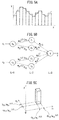
- FIG. 1 is an overall view of an internal combustion engine.
- FIG. 2 is a view showing one example of a neural network.
- FIG. 3A and FIG. 3B are views showing changes in values of a Sigmoid function ⁇ .
- FIG. 4A and FIG. 4B respectively are views showing a neural network and output values from nodes of a hidden layer.
- FIG. 5A is a view showing an output value from a node of an output layer
- FIG. 5B is a view showing a neural network
- FIG. 5C is a view showing an output value from a node of an output layer.
- FIG. 6A and FIG. 6B respectively are a functional block diagram of a first embodiment and a view showing a learning routine.
- FIG. 7 is a view showing a neural network used in the first embodiment according to the present invention.
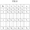
- FIG. 8 is a view showing a learning use data set.
- FIG. 9 is a flow chart showing a learning routine.
- FIG. 10A and FIG. 10B are views showing an estimated bed temperature of an exhaust purification catalyst.
- FIG. 11A and FIG. 11B are views showing an estimated bed temperature of an exhaust purification catalyst.
- FIG. 12 is a view showing a neural network used in a second embodiment according to the present invention.
- FIG. 13A and FIG. 13B are views showing a learning use data set.
- FIG. 14A and FIG. 14B respectively are views showing a relationship between measured values and predicted values of HC concentration and a relationship between measured values and predicted values of CO concentration.
- FIG. 15 is a functional block diagram showing still another embodiment according to the present invention.
- FIG. 16 is a functional block diagram showing still another embodiment according to the present invention.
- FIG. 1 shows the overall configuration of an internal combustion engine.
- 1 shows an engine body, 2 combustion chambers of the cylinders, 3 spark plugs arranged in the combustion chambers 2 of the cylinders, 4 fuel injectors for injecting fuel, for example, gasoline, to the cylinders, 5 a surge tank, 6 intake branch pipes, and 7 an exhaust manifold.
- the surge tank 5 is connected through an intake duct 8 to the outlet of a compressor 9 a of an exhaust turbocharger 9 , while the inlet of the compressor 9 a is connected through an intake air amount detector 10 to an air cleaner 11 .
- a throttle valve 12 driven by an actuator 13 is arranged and, around the intake duct 8 , an intercooler 14 is arranged for cooling the intake air flowing through the inside of the intake duct 8 .
- the exhaust manifold 7 is connected to the inlet of the exhaust turbine 9 b of the exhaust turbocharger 9 , while the outlet of the exhaust turbine 9 b is connected through an exhaust pipe 15 to a catalytic converter 17 having an exhaust purification catalyst 16 therein.
- this exhaust purification catalyst 16 is comprised of a three way catalyst.
- the exhaust manifold 7 and the surge tank 5 are connected with each other through an exhaust gas recirculation (below, referred to as “EGR”) passage 18 . Inside the EGR passage 18 , an EGR control valve 19 is arranged.
- Each fuel injector 4 is connected to a fuel distribution pipe 20 .
- This fuel distribution pipe 20 is connected through a fuel pump 21 to a fuel tank 22 . As shown in FIG.
- an air-fuel ratio sensor 25 for detecting the air-fuel ratio of the exhaust gas and a HC concentration sensor 26 for detecting the HC concentration in the exhaust gas or a CO concentration sensor 26 for detecting the CO concentration in the exhaust gas are arranged in the exhaust pipe 15 .
- a temperature sensor 27 for detecting the temperature of the exhaust purification catalyst 16 is arranged in the exhaust purification catalyst 16 .
- An electronic control unit 30 is comprised of a digital computer provided with a ROM (read only memory) 32 , RAM (random access memory) 33 , CPU (microprocessor) 34 , input port 35 , and output port 36 , which are connected with each other by a bidirectional bus 31 .
- ROM read only memory
- RAM random access memory
- CPU microprocessor
- input port 35 output signals of the intake air amount detector 10 , pressure sensor 23 , temperature sensor 24 , air-fuel ratio sensor 25 , HC concentration sensor 26 or CO concentration sensor 26 , and temperature sensor 27 are input through corresponding AD converters 37 .
- a load sensor 41 generating an output voltage proportional to the amount of depression of the accelerator pedal 40 is connected. The output voltage of the load sensor 41 is input through the corresponding AD converter 37 to the input port 35 .
- the input port 35 is connected to a crank angle sensor 42 generating an output pulse each time a crankshaft rotates by for example 30°.
- the engine speed is calculated based on the output signals of the crank angle sensor 42 .
- the output port 36 is connected through corresponding drive circuits 38 to the spark plugs 3 , the fuel injectors 4 , the throttle valve drive use actuator 13 , EGR control valve 19 , and fuel pump 21 .
- FIG. 2 shows one example of a neural network.
- the circle marks in FIG. 2 show artificial neurons.
- these artificial neurons are usually called “node” or “unit” (in the present application, they are called “node”).
- the number of hidden layers may be made one or any other number, while the number of nodes of the input layer and number of nodes of the hidden layers may also be made any numbers. Note that, in the embodiments according to the present invention, the number of nodes of the output layer is made one node.
- the inputs are output as they are.
- the respectively corresponding weights “w” and biases “b” are used to calculate the sum input value u( ⁇ z ⁇ w+b).
- this activating function a Sigmoid function ⁇ is used as this activating function.
- the output values z 1 and z 2 of the nodes of the other hidden layer are input.
- the respectively corresponding weights “w” and biases “b” are used to calculate the sum input value u( ⁇ z ⁇ w+b) or just the respectively corresponding weights “w” are used to calculate the sum input value u( ⁇ z ⁇ w).
- an identity function is used, therefore, from the node of the output layer, the sum input value “u” calculated at the node of the output layer is output as it is as the output value “y”.
- This input value “u” is converted by the Sigmoid function ⁇ (x ⁇ w 1 (L2) +b j ) and output as the output value z 1 .
- This input value “u” is converted by the Sigmoid function ⁇ (x ⁇ w 2 (L2) +b 2 ) and output as the output value z 2 .
- an identity function is used at the node of the output layer. Therefore, from the node of the output layer, the sum input value “u” calculated at the node of the output layer is output as is as the output value “y”.
- FIG. 4B shows a case where the value of the Sigmoid function ⁇ is made to change in steps as shown in FIG. 3B by increasing the value of the weights w 1 (L2) and w 2 (L2) .
- FIG. 4B shows a case where the value of the Sigmoid function ⁇ is made to change in steps as shown in FIG. 3B by increasing the value of the weights w 1 (L2) and w 2 (L2) .
- the output values z 1 and z 2 are multiplied with the respectively corresponding weights w 1 (y) and w 2 (y) .
- FIG. 4B (III) the change in the output value “y” when w 1 (y) and w 2 (y) >1 is shown by the broken line.
- the function When there are two input values, the function is expressed in a three-dimensional space by the two input values+one output value. That is, when there are “n” input values, the function is expressed on an n+1 dimensional plane by the n input value+one output value. Note that it is not possible to express a space of a four-dimensional or higher plane on a sheet of paper, so such an illustration is omitted.
- a Sigmoid function is selected, but in principle it may also be a function which monotonously increases and can be differentiated.
- the gradient descent method is used, and the reason for using a Sigmoid function is to facilitate calculation by using the later explained error back propagation method when using the gradient descent method. Therefore, if calculation by the gradient descent method is possible, a Sigmoid function need not be used. Further, the gradient descent method is used because analytic calculation is not possible, but if analytic calculation is possible, there is no need to use the gradient descent method.
- an error backpropagation algorithm is used to learn the values of the weights “w” and biases “b” in a neural network.
- This error backpropagation algorithm is known. Therefore, the error backpropagation algorithm will be explained simply below in its outlines. Note that, a bias “b” is one kind of weight “w”, so in the following explanation, a bias “b” is deemed one type of weight “w”. Now then, in the neural network such as shown in FIG.
- the differential of the error function E that is, gradient ⁇ E/ ⁇ w (L) , is found for each weight “w”. If the gradient ⁇ E/ ⁇ w (L) is found, this gradient ⁇ E/ ⁇ w (L) is used to update the value of the weight “w” so that the value of the error function E decreases. That is, the value of the weight “w” is learned. Note that, when as the training data, a batch or minibatch is used, as the error function E, the following mean squared error E is used:
- “fuel increasing control” for increasing the amount of fuel injection to lower the temperature of the exhaust purification catalyst by the latent heat of evaporation of the fuel to prevent the exhaust purification catalyst from overheating when the temperature of the exhaust purification catalyst exceeds a certain setting, that is, “OT increase control”, is performed, and “SO X release control” for releasing the stored SO X from the NO X storage and reduction catalyst by making the air-fuel ratio of the exhaust gas flowing into the NO X storage and reduction catalyst rich in the state where the temperature of the NO X storage and reduction catalyst is raised to the SO X release temperature when a large amount of SO X is stored in the NO X storage and reduction catalyst is performed.
- These OT increase control and SO X release control are performed according to the temperature of the catalyst, and accordingly, to perform such OT increase control and SO X release control, it is necessary to estimate the temperature of the catalyst.
- the HC and CO contained in exhaust gas react with the oxygen contained in the exhaust gas and the oxygen deposited on the exhaust purification catalyst on the exhaust purification catalyst to generate the heat of oxidation reaction.
- This heat of oxidation reaction generated in the exhaust purification catalyst greatly affects the temperature of the catalyst. Therefore, it can be said to be preferable to also use the HC concentration or CO concentration in the exhaust gas as one of the engine operating parameters for estimating the temperature of the catalyst.
- the number of maps is limited, so it is difficult to further add maps relating to the HC concentration and CO concentration.
- the present invention uses a neural network to precisely predict the temperature of the exhaust purification catalyst of the internal combustion engine.
- the present invention uses a neural network to precisely predict a temperature of an exhaust purification catalyst of an internal combustion engine.
- a machine learning device is used.
- the operating parameters having an effect on the temperature of the catalyst that is, as the variables showing the operating state, the values of the engine speed, the engine load rate, the air-fuel ratio of the engine, the ignition timing of the engine, the HC or CO concentration of the exhaust gas flowing into the exhaust purification catalyst, and the temperature of the exhaust purification catalyst are employed. As shown in FIG.
- the machine learning device 50 comprises a state acquiring unit 51 for acquiring state variables comprised of the engine speed, the engine load rate, the air-fuel ratio of the engine, the ignition timing of the engine, the HC or CO concentration of the exhaust gas flowing into the exhaust purification catalyst, and the temperature of the exhaust purification catalyst.
- a training data set is prepared showing the relationships among the engine speed, the engine load rate, the air-fuel ratio of the engine, the ignition timing of the engine, and the HC or CO concentration of the exhaust gas flowing into the exhaust purification catalyst and the temperature of the exhaust purification catalyst.
- the machine learning device 50 is provided with a learning unit 52 for learning the temperature of the exhaust purification catalyst according to this training data set.
- the machine learning device 50 shown in this example is comprised of a state acquiring unit 51 for acquiring state variables comprised of the engine speed, the engine load rate, the air-fuel ratio of the engine, the ignition timing of the engine, the HC or CO concentration of the exhaust gas flowing into the exhaust purification catalyst, and the temperature of the exhaust purification catalyst and a learning unit 52 learning the temperature of the exhaust purification catalyst according to the training data set comprised of these state variables.
- FIG. 6B shows a learning routine performed in the machine learning device 50 shown in FIG. 6A .
- state variables comprised of the engine speed, the engine load rate, the air-fuel ratio of the engine, the ignition timing of the engine, the HC or CO concentration of the exhaust gas flowing into the exhaust purification catalyst, and the temperature of the exhaust purification catalyst are acquired.
- step 54 the temperature of the exhaust purification catalyst is learned according to the training data set comprised of these state variables.
- FIG. 7 shows a machine learning device 55 for predicting a catalyst temperature.
- x 1 ”, “x 2 ”, “x 3 ”, “x 4 ”, and “x 5 ” sometimes indicate input parameters and sometimes indicate values of the input parameters.
- the output value from the node of the output layer is shown by “y”.
- the input values showing the values of the operating parameters in FIG. 7 that is, the input values x 1 , x 2 , x 3 , x 4 , and x 5 of the input parameters, and the output value “y” of the output parameter will be explained.
- the operating parameters that is, as the input parameters, the engine speed, the engine load rate, the air-fuel ratio of the engine, the ignition timing of the engine, and the HC or CO concentration of the exhaust gas flowing into the exhaust purification catalyst are employed.
- x 1 shows the engine speed
- x 1 shows the engine load rate
- x 3 shows the air-fuel ratio of the engine
- “x 4 ” shows the ignition timing of the engine
- x 5 shows the HC or CO concentration of the exhaust gas flowing into the exhaust purification catalyst.
- the engine speed is calculated in the CPU 34 in the electronic control unit 30 .
- This calculated value is used as the engine speed.
- the engine load rate shows the ratio of the actual amount of intake air to the amount of intake air to the inside of the engine cylinders at the time of engine full load operation.
- the amounts of intake air at the time of engine full load operation at certain reference intake air temperatures and intake air pressures are measured in advance with respect to typical engine speeds.
- the measured values are stored in a storage unit (ROM 32 or RAM 33 ) of the electronic control unit 30 .
- an actual amount of intake air is found by correcting an amount of intake air detected by the intake air amount detector 10 to become the value at the above-mentioned reference intake air temperature and intake air pressure using the detected values of the pressure sensor 23 and temperature sensor 24 .
- the engine load rate is calculated from the stored amounts of intake air at the time of engine full load operation and the corrected actual amount of intake air, and this calculated value is used as the engine load rate.
- the air-fuel ratio of the engine is acquired from an output signal of the air-fuel ratio sensor 25 .
- the ignition timing of the engine is, for example, stored in advance as a function of the engine speed and the engine load rate in a storage unit (ROM 32 or RAM 33 ) of the electronic control unit 30 .
- This ignition timing of the engine is calculated in the CPU 34 from the engine speed and the load factor of the engine, and this calculated value is used as the ignition timing of the engine.
- the HC or CO concentration in the exhaust gas flowing into the exhaust purification catalyst 16 is acquired from the output signal from the HC concentration sensor 26 or CO concentration sensor 26 . In this case, either of the HC concentration sensor 26 or CO concentration sensor 26 is used.
- the HC concentration and the CO concentration can also be detected using a gas analyzer which samples the exhaust gas to analyze the components of the exhaust gas.
- the temperature of the exhaust purification catalyst 16 is acquired from the output signal of the temperature sensor 27 .
- the measured values of the input parameters and the measured value of the output parameter in different operating states when randomly changing the operating states of the engine are, as shown in FIG. 8 , stored as the learning use data set in a storage unit (ROM 32 or RAM 33 ) of the electronic control unit 30 .
- ROM 32 or RAM 33 the storage unit
- FIG. 8 shows the measured values of the input parameters and the measured value of the output parameter for N number of operating states. Note that, in FIG.
- “x 1 ” shows the engine speed
- “x 2 ” shows the engine load rate
- “x 3 ” shows the air-fuel ratio of the engine
- “x 4 ” shows the ignition timing of the engine
- “x 5 ” shows the HC or CO concentration of the exhaust gas flowing into the exhaust purification catalyst.
- “yt” shows the measured value of the output parameter, that is, the measured value of the temperature of the exhaust purification catalyst 16 .
- the measured value yt of the temperature of the exhaust purification catalyst 16 is used as the training data.
- the measured values of the input parameters x 1 , x 2 , x 3 , x 4 , and x 5 in the No. 1 operating state are respectively shown by “a 1 ”, “b 1 ”, “c 1 ”, “d 1 ”, and “e 1 ”, while the value of the measured value yt of the temperature of the exhaust purification catalyst 16 is shown by “f 1 ”.
- the learning use data set shown in FIG. 8 is used to learn the weight of the neural network of the machine learning device 55 shown in FIG. 7 .
- One example of the learning routine of the weight of the neural network is shown in FIG. 9 .
- step 61 the learning use data set of the ordinal number No. “n” showing the operating state in FIG. 8 is read in.
- the routine proceeds to step 62 .
- step 64 it is judged if the ordinal number “n” of the operating state becomes N, that is, if the weight of the neural network has been learned for all of the learning use data sets shown in FIG. 8 . If at step 64 it is judged that the ordinal number “n” of the operating states does not become N, the routine returns to step 61 .
- step 64 it is judged that the ordinal number “n” of the operating state becomes N, that is, if the weight of the neural network has been learned for all of the learning use data sets shown in FIG. 8 , the routine proceeds to step 65 .
- the above formula (8) is used to calculate a square sum error E between the output value “y” and the training data yt of the neural network, and it is judged if this square sum error E becomes a preset error setting or less.
- the learning routine is ended.
- the routine returns to step 60 and the weight of the neural network is again learned for all of the learning use data set shown in FIG. 8 .
- the weight of the neural network continues to be learned until the square sum error E becomes the preset error setting or less.
- a learning data set showing relationships among an engine speed, an engine load rate, an air-fuel ratio of the engine, an ignition timing of the engine, and an HC or CO concentration of the exhaust gas flowing into the exhaust purification catalyst and a temperature of the exhaust purification catalyst 16 is acquired, and the acquired engine speed, engine load rate, air-fuel ratio of the engine, ignition timing of the engine, and HC or CO concentration of the exhaust gas flowing into the exhaust purification catalyst are used as input parameters of the neural network.
- the acquired temperature of the exhaust purification catalyst is used as training data to learn a weight of the neural network, and the learned neural network is used to estimate the temperature of the exhaust purification catalyst 16 .
- the internal combustion engine is provided with the electronic control unit 30 .
- the electronic control unit 30 is provided with an input parameter value acquiring unit for acquiring the values of input parameters relating to operation of the engine, a processing unit for processing using a neural network comprised of an input layer, a hidden layer, and an output layer, and a storage unit.
- the input port 35 forms the above-mentioned parameter value acquiring unit
- the CPU 34 forms the above-mentioned processing unit
- the ROM 32 and RAM 33 form the above-mentioned storage unit.
- the values of the operating parameters of the engine are input to the input layer, while the output value, which changes in accordance with the values of the operating parameters of the engine, is output from the output layer.
- the input parameter value acquiring unit acquires the engine speed, the engine load rate, the air-fuel ratio of the engine, the ignition timing of the engine, the HC or CO concentration in the exhaust gas flowing into the exhaust purification catalyst 16 , and the temperature of the exhaust purification catalyst 16 .
- the relationships among the engine speed, the engine load rate, the air-fuel ratio of the engine, the ignition timing of the engine, and the HC or CO concentration in the exhaust gas flowing into the exhaust purification catalyst 16 and the temperature of the exhaust purification catalyst 16 are stored as a learning use data set in the storage unit.
- the engine speed, the engine load rate, the air-fuel ratio of the engine, the ignition timing of the engine, and the HC or CO concentration in the exhaust gas flowing into the exhaust purification catalyst 16 stored in this storage unit as the learning use data set are used as input to the input layer of a neural network while the temperature of the exhaust purification catalyst 16 stored as learning use data set in the storage unit is used as training data to learn the weight of the neural network.
- the estimated value of the temperature of the exhaust purification catalyst 16 is output from the output layer of the learned neural network.
- FIG. 10A shows the relationship between the estimated temperature T 0 and measured temperature T 0 of the exhaust purification catalyst 16 when using a plurality of maps showing the relationships of the engine speed, the engine load rate, the air-fuel ratio of the engine, the ignition timing of the engine, and the temperature of the exhaust purification catalyst 16 to estimate the temperature of the exhaust purification catalyst 16 .
- FIG. 10B shows the relationship between the estimated temperature T 0 and measured temperature T 0 of the exhaust purification catalyst 16 when using the engine speed, the engine load rate, the air-fuel ratio of the engine, the ignition timing of the engine, and the CO concentration in the exhaust gas flowing into the exhaust purification catalyst 16 as the input parameters of the neural network and using the acquired temperature of the exhaust purification catalyst 16 as the training data to learn the weight of the neural network.
- the precision of estimation of the temperature of the exhaust purification catalyst 16 is higher in the case shown in FIG. 10B .
- the correlation coefficient R 2 between the estimated temperature and the measured temperature in the case shown in FIG. 10A is 0.4881
- the correlation coefficient R 2 between the estimated temperature and the measured temperature in the case shown in FIG. 10B is 0.8973.
- FIG. 11A shows a comparison of the temporal changes of the measured temperature T 0 and the estimated temperature T 0 when using a plurality of maps showing the relationship of the engine speed, the engine load rate, the air-fuel ratio of the engine, the ignition timing of the engine, and the temperature of the exhaust purification catalyst 16 to estimate the temperature of the exhaust purification catalyst 16
- FIG. 11A shows a comparison of the temporal changes of the measured temperature T 0 and the estimated temperature T 0 when using a plurality of maps showing the relationship of the engine speed, the engine load rate, the air-fuel ratio of the engine, the ignition timing of the engine, and the temperature of the exhaust purification catalyst 16 to estimate the temperature of the exhaust purification catalyst 16
- FIG. 11A shows a comparison of the temporal changes of the measured temperature T 0 and the estimated temperature T 0 when using a plurality of maps showing the relationship of the engine speed, the engine load rate, the air-fuel ratio of the engine, the ignition timing of the engine, and the temperature of the exhaust purification catalyst 16 to estimate the temperature of the
- 11B shows a comparison of the temporal changes of the estimated temperature T 0 and measured temperature T 0 of the exhaust purification catalyst 16 when using the engine speed, the engine load rate, the air-fuel ratio of the engine, the ignition timing of the engine, and the CO concentration in the exhaust gas flowing into the exhaust purification catalyst 16 as the input parameters of the neural network and using the acquired temperature of the exhaust purification catalyst 16 as training data to learn the weight of the neural network. If comparing FIG. 11A and FIG. 11B , it will be understood that compared with the case shown in FIG. 11A , the precision of estimation of the temperature of the exhaust purification catalyst 16 is higher in the case shown in FIG. 11B .
- the machine learning device is comprised of a machine learning device 70 for predicting the catalyst temperature and a machine learning device 71 for estimating the HC or CO concentration in the exhaust gas flowing into the exhaust purification catalyst 16 .
- these machine learning device 70 and 71 are comprised of neural networks formed inside the ROM 32 of the electronic control unit 30 .
- “x 1 ”, “x 2 ”, and “x 3 ” sometimes indicate input parameters and sometimes indicate values of the input parameters.
- the input values showing the values of the operating parameters in the machine learning device 71 that is, the input values x 1 , x 2 , and x 3 of the input parameters, and the output value y′ of the output parameter
- the operating parameters that is, the input parameters
- the machine learning device 70 is comprised of a neural network of the same configuration as the machine learning device 55 shown in FIG. 7 . Therefore, the explanation of the configuration of the neural network of the machine learning device 70 will be omitted, while only the input values showing the values of the operating parameters, that is, the input values x 1 , x 2 , x 3 , x 4 , and x 5 of the input parameters, and the output value “y” of the output parameter will be explained.
- the input values x 1 , x 2 , x 3 , and x 4 are the same as in the machine learning device 55 shown in FIG.
- the input value x 5 differs from that of the machine learning device 55 shown in FIG. 7 .
- the operating parameters that is, as the input parameters, the engine speed, the engine load rate, the air-fuel ratio of the engine, the ignition timing of the engine, and the estimated values of the HC or CO concentration in the exhaust gas flowing into the exhaust purification catalyst 16 are employed.
- FIG. 13A shows the learning use data set for estimating the HC or CO concentration in the exhaust gas flowing into the exhaust purification catalyst 16 in the machine learning device 71 of FIG. 12
- FIG. 13B shows the learning use data set for predicting the catalyst temperature in the machine learning device 70 of FIG. 12 .
- the learning use data set for estimating the HC or CO concentration in the exhaust gas shown in FIG. 13A will be explained.
- the measured values of the values of the input parameters and the measured value of the value of the output parameter in different operating states when randomly changing the operating states of the engine are, as shown in FIG. 13A , stored as the learning use data set in a storage unit (ROM 32 or RAM 33 ) of the electronic control unit 30 .
- the measured values of the input parameters and the measured value of the output parameter are found for N number of operating states.
- x 1 shows the engine speed
- x 1 shows the engine load rate
- x 3 shows the air-fuel ratio of the engine.
- yt′ shows the measured value of the HC or CO concentration in the exhaust gas flowing into the exhaust purification catalyst 16 , that is, the training data.
- the HC or CO concentration in the exhaust gas flowing into the exhaust purification catalyst 16 is acquired from the output signal of the HC concentration sensor 26 or CO concentration sensor 26 or is detected using a gas analyzer for analyzing the components of sampled exhaust gas.
- the values of the input parameters x 1 , x 2 , and x 3 in the No. 1 operating state are shown by “a 1 ,” “b 1 ,” and “c 1 ”, while the measured value yt′ of the HC or CO concentration in the exhaust gas, that is, the value of the teacher data yt′, is shown by “y 1 ′”.
- the values of the input parameters x 1 , x 2 , and x 3 in the No. “n” operating state are respectively shown by a n , b n , and c n
- the measured value yt′ of the HC or CO concentration in the exhaust gas that is, the value of the teacher data yt′
- the learning use data set shown in FIG. 13A is used to learn the weight of the neural network of the machine learning apparatus 71 shown in FIG. 12 .
- the weight of the neural network is learned using the learning routine shown in FIG. 9 .
- the engine speed, the engine load rate, and the air-fuel ratio of the engine acquired from the learning use data set are used as the input parameters of the neural network and the HC or CO concentration in the exhaust gas flowing into the exhaust purification catalyst 16 acquired from the learning use data set is used as the training data to learn the weight of the neural network and this learned neural network is used to find the estimated value of the HC or CO concentration in the exhaust gas flowing into the exhaust purification catalyst 16 .
- the learning use data set shown in FIG. 13B is similar to the learning use data set shown in FIG. 8 . It differs from the learning use data set shown in FIG. 8 just in using as the input value of the input parameter x 5 the output value y′ from the machine learning device 71 , that is, the estimated value y′ of the HC or CO concentration in the exhaust gas flowing into the exhaust purification catalyst 16 .
- the learning use data set shown in FIG. 13B is the same as the learning use data set shown in FIG. 8 on the other points. That is, in the learning use data set shown in FIG. 13B , “x 1 ” shows the engine speed, “x 2 ” shows the engine load rate, “x 3 ” shows the air-fuel ratio of the engine, and “x 4 ” shows the ignition timing of the engine.
- the learning use data set shown in FIG. 13B is used to learn the weight of the neural network of the machine learning device 70 shown in FIG. 12 . This weight of the neural network is learned using the learning routine shown in FIG. 9 .
- FIG. 14A shows the relationship between a measured value DM) and an estimated value DM) when using the machine learning device 71 shown in FIG. 12 to estimate an HC concentration (ppm) DH in the exhaust gas flowing into the exhaust purification catalyst 16
- FIG. 14B shows the relationship between a measured value DC 0 and an estimated value DC 0 when using the machine learning device 71 shown in FIG. 12 to estimate a CO concentration (ppm) DC in the exhaust gas flowing into the exhaust purification catalyst 16 .
- the HC or CO concentration in the exhaust gas flowing into the exhaust purification catalyst 16 is acquired from the output signal of the HC concentration sensor 26 or CO concentration sensor 26 or is detected using a gas analyzer analyzing the components of the sampled exhaust gas. Therefore, when using the machine learning device 70 shown in FIG. 12 to predict the catalyst temperature, it can be said to be preferable to use the CO concentration sensor 26 to detect the CO concentration in the exhaust gas or use a gas analyzer to detect the CO concentration in the exhaust gas.
- the machine learning device 71 finishes machine learning of the CO concentration in the exhaust gas, the CO concentration sensor 26 or gas analyzer become unnecessary. Therefore, the second embodiment according to the present invention can be said to be suited for the case of predicting the catalyst temperature on-board.
- the learning use data set and the test data for validation of the precision suitable combinations of data can be selected from all data.
- the holdout validation method is used, but the cross validation method may also be used to validate the machine learning.
- a learned model for estimating the temperature of the exhaust purification catalyst is prepared by using a neural network from the engine speed, the engine load rate, the air-fuel ratio of the engine, the ignition timing of the engine, and the HC or CO concentration of the exhaust gas flowing into the exhaust purification catalyst.
- this learned model is built into the electronic control unit 30 .
- this electronic control unit is comprised of an electronic control unit which has built into it a learned model.
- This learned model is generated by acquiring a learning use data set prepared based on values of the pressure sensor 23 , temperature sensor 24 , air-fuel ratio sensor 25 , HC concentration or CO concentration sensor 26 or gas analyzer, temperature sensor 27 and the values calculated in a CPU 34 of the electronic control unit 30 , which learning use data set showing the relationships among the engine speed, the engine load rate, the air-fuel ratio of the engine, the ignition timing of the engine, the HC or CO concentration of the exhaust gas flowing into the exhaust purification catalyst and the temperature of the exhaust purification catalyst, and by learning the weight of the neural network.
- the weight of the neural network is learned by using the acquired engine speed, the engine load rate, air-fuel ratio of the engine, ignition timing of the engine, and HC or CO concentration of the exhaust gas flowing into the exhaust purification catalyst as input parameters of a neural network and by using the acquired temperature of the exhaust purification catalyst as training data.
- the learned model is comprised of a learned model which is generated by acquiring a learning use data set prepared based on values of the pressure sensor 23 , temperature sensor 24 , air-fuel ratio sensor 25 , HC concentration or CO concentration sensor 26 or gas analyzer, temperature sensor 27 and the values calculated in a CPU 34 of the electronic control unit 30 , which learning use data set showing the relationships among the engine speed, the engine load rate, the air-fuel ratio of the engine, the ignition timing of the engine, the HC or CO concentration of the exhaust gas flowing into the exhaust purification catalyst and the temperature of the exhaust purification catalyst, and by learning the weight of the neural network.
- the weight of the neural network is learned by using the acquired engine speed, the engine load rate, air-fuel ratio of the engine, ignition timing of the engine, and HC or CO concentration of the exhaust gas flowing into the exhaust purification catalyst as input parameters of a neural network and by using the acquired temperature of the exhaust purification catalyst as training data.
- an electronic control unit when producing an electronic control unit, it is possible to incorporate a learned neural network inside the electronic control unit as a learned model. Therefore, in the embodiment of the present invention, as a method of production of an electronic control unit, use may be made of a method of production of an electronic control unit by incorporating a learned neural network inside the electronic control unit as a learned model.
- this learned model is generated by acquiring a learning use data set prepared based on values of the pressure sensor 23 , temperature sensor 24 , air-fuel ratio sensor 25 , HC concentration or CO concentration sensor 26 or gas analyzer, temperature sensor 27 and the values calculated in a CPU 34 of the electronic control unit 30 , which learning use data set showing the relationships among the engine speed, the engine load rate, the air-fuel ratio of the engine, the ignition timing of the engine, the HC or CO concentration of the exhaust gas flowing into the exhaust purification catalyst and the temperature of the exhaust purification catalyst, and by learning the weight of the neural network.
- the weight of the neural network is learned by using the acquired engine speed, the engine load rate, air-fuel ratio of the engine, ignition timing of the engine, and HC or CO concentration of the exhaust gas flowing into the exhaust purification catalyst as input parameters of a neural network and by using the acquired temperature of the exhaust purification catalyst as training data.
- FIG. 15 is an overall view showing one example of a machine learning system for predicting a temperature of an exhaust purification catalyst of an internal combustion engine.
- 71 indicates a vehicle
- 72 indicates a server 72 set outside the vehicle 71 .
- the engine speed, the engine load rate, the air-fuel ratio of the engine, the ignition timing of the engine, the HC or CO concentration of the exhaust gas flowing into the exhaust purification catalyst, and the temperature of the exhaust purification catalyst are found.
- the server 72 comprises a communicating unit 73 communicating with the vehicle 71 , an engine speed acquiring unit 4 for acquiring an engine speed from the vehicle 71 through the communicating unit 73 , an engine load rate acquiring unit 75 for acquiring the engine load rate from the vehicle 71 through the communicating unit 73 , an air-fuel ratio acquiring unit 76 for acquiring the air-fuel ratio of the engine from the vehicle 71 through the communicating unit 73 , an ignition timing acquiring unit 77 for acquiring the ignition timing of the engine from the vehicle 71 through the communicating unit 73 , a concentration acquiring unit 78 for acquiring the HC or CO concentration of the exhaust gas flowing into an exhaust purification catalyst from the vehicle 71 through the communicating unit 73 , an exhaust purification catalyst temperature acquiring unit 79 for acquiring the temperature of the exhaust purification catalyst from the vehicle 71 through the communicating unit 73 , a data set preparing unit 80 using the acquired engine speed, engine load rate, air-fuel ratio of the engine, ignition timing
- this machine learning system for predicting a temperature of an exhaust purification catalyst of an internal combustion engine comprises an engine speed acquiring unit 74 for acquiring an engine speed, an engine load factor acquiring unit 75 for acquiring a load factor of the engine, an air-fuel ratio acquiring unit 76 for acquiring an air-fuel ratio of the engine, an ignition timing acquiring unit 77 for acquiring an ignition timing of the engine, a concentration acquiring unit 78 for acquiring an HC or CO concentration of the exhaust gas flowing into the exhaust purification catalyst, an exhaust purification catalyst temperature acquiring unit 79 for acquiring a temperature of the exhaust purification catalyst, a data set preparing unit 80 for preparing a data set using the acquired engine speed, engine load rate, air-fuel ratio of the engine, ignition timing of the engine, HC or CO concentration, and exhaust purification catalyst temperature, and a learning unit 81 for learning a temperature of the exhaust purification catalyst based on this data set.
- data relating to the engine speed, engine load rate, air-fuel ratio of the engine, ignition timing of the engine, HC or CO concentration of the exhaust gas flowing into the exhaust purification catalyst, and temperature of the exhaust purification catalyst acquired in the vehicle 71 is received from the communicating unit 73 of the server 72 .
- the received engine speed, the engine load rate, air-fuel ratio of the engine, ignition timing of the engine, HC or CO concentration of the exhaust gas flowing into the exhaust purification catalyst, and temperature of the exhaust purification catalyst are used to prepare a data set.
- the temperature of the exhaust purification catalyst is learned in accordance with this data set.
- FIG. 16 shows an overall view of another example of a machine learning system for predicting the temperature of the exhaust purification catalyst of an internal combustion engine.
- 71 shows a vehicle
- 72 shows a server set outside of the vehicle 71 .
- This server 72 also, in the same way as the server 72 shown in FIG.
- a communicating unit 73 for communicating with the vehicle 71 , an engine speed acquiring unit 74 for acquiring an engine speed, an engine load rate acquiring unit 75 for acquiring an engine load rate, an air-fuel ratio acquiring unit 76 for acquiring an air-fuel ratio of the engine, an ignition timing acquiring unit 77 for acquiring an ignition timing of the engine, a concentration acquiring unit 78 for acquiring an HC or CO concentration of the exhaust gas flowing into the exhaust purification catalyst, an exhaust purification catalyst temperature acquiring unit 79 for acquiring a temperature of the exhaust purification catalyst, a data set preparing unit 80 for preparing a data set using the acquired engine speed, engine load rate, air-fuel ratio of the engine, ignition timing of the engine, HC or CO concentration, and exhaust purification catalyst temperature, and a learning unit 81 for learning the temperature of the exhaust purification catalyst in accordance with this data set.
- the vehicle 71 is provided with a communicating unit 82 for communicating with the server 72 in addition to the vehicle-mounted electronic control unit 30 .
- data relating to the engine speed, engine load rate, air-fuel ratio of the engine, ignition timing of the engine, HC or CO concentration of the exhaust gas flowing into the exhaust purification catalyst, and temperature of the exhaust purification catalyst acquired in the vehicle 71 is transmitted from the communicating unit 82 of the vehicle 71 to the communicating unit 73 of the server 72 , a data set is prepared using the engine speed, engine load rate, air-fuel ratio of the engine, ignition timing of the engine, HC or CO concentration of the exhaust gas flowing into the exhaust purification catalyst, and temperature of the exhaust purification catalyst received at the communicating unit 73 , and the temperature of the exhaust purification catalyst is learned in accordance with this data set.
- the learned model of the temperature of the exhaust purification catalyst is transmitted from the communicating unit 73 of the server 72 to the communicating unit 82 of the vehicle 71 .
- the weight of the neural network in the vehicle-mounted electronic control unit 30 is updated by the learned model received at the communicating unit 82 .
- data showing the engine speed, the engine load rate, the air-fuel ratio of the engine, the ignition timing of the engine, the HC or CO concentration of exhaust gas flowing into the exhaust purification catalyst, and the temperature of the exhaust purification catalyst is acquired in the vehicle, this data is transmitted to the server, a learned model is generated in the server by using the received engine speed, engine load rate, air-fuel ratio of the engine, ignition timing of the engine, and HC or CO concentration of the exhaust gas flowing into the exhaust purification catalyst as input parameters of a neural network and by using the received temperature of the exhaust purification catalyst as training data to learn a weight of the neural network, the generated learned model is transmitted to the vehicle, and the temperature of the exhaust purification catalyst of the internal combustion engine is predicted by using the learned model from the acquired engine speed, engine load rate, air-fuel ratio of the engine, ignition timing of the engine, and HC or CO concentration of the exhaust gas flowing into the exhaust purification catalyst.
- the server comprises the communicating unit 73 for communicating with the vehicle 71 , the engine speed acquiring unit 74 for acquiring the engine speed, the engine load rate acquiring unit 75 for acquiring the engine load rate, the air-fuel ratio acquiring unit 76 for acquiring the air-fuel ratio of the engine, the ignition timing acquiring unit 77 for acquiring the ignition timing of the engine, the concentration acquiring unit 78 for acquiring the HC or CO concentration of the exhaust gas flowing into the exhaust purification catalyst, the exhaust purification catalyst temperature acquiring unit 79 for acquiring the temperature of the exhaust purification catalyst, the data set preparing unit 80 for preparing a data set using the acquired engine speed, engine load rate, air-fuel ratio of the engine, ignition timing of the engine, HC or CO concentration, and exhaust purification catalyst temperature, and the learning unit 81 for learning the temperature of the exhaust purification catalyst in accordance with the data set.
- the present machine learning handles output forming a continuous value as a problem of regression, but the output may also be considered as a problem of classification of a finite number of discrete categories (multiclass classification). Specifically, it is sufficient to prepare several classes as output and link the classes and the temperatures of the catalyst.
- machine learning there are various methods for supervised learning besides a neural network such as the Random forest, support vector machine, and k neighbor algorithm. These models are common on the point of being algorithms which lay boundary lines in feature spaces laid by feature vectors and efficiently find the decision boundaries. That is, if possible to be estimated by a neural network, machine learning is possible by other supervised learning models as well.
- a neural network such as the Random forest, support vector machine, and k neighbor algorithm.
- machine learning instead of using supervised learning, it is also possible to use semi supervised learning.
Abstract
Description
-
- an engine speed acquiring unit for acquiring an engine speed,
- an engine load rate acquiring unit for acquiring an engine load rate,
- an air-fuel ratio acquiring unit for acquiring an air-fuel ratio of the engine,
- an ignition timing acquiring unit for acquiring an ignition timing of the engine,
- a concentration acquiring unit for acquiring an HC or CO concentration of exhaust gas flowing into the exhaust purification catalyst,
- an exhaust purification catalyst temperature acquiring unit for acquiring a temperature of the exhaust purification catalyst,
- a data set preparing unit for preparing a data set using the acquired engine speed, engine load rate, air-fuel ratio of the engine, ignition timing of the engine, HC or CO concentration, and exhaust purification catalyst temperature, and
- a learning unit for learning the temperature of the exhaust purification catalyst in accordance with the data set.
-
- the server comprising:
- an engine speed acquiring unit for acquiring an engine speed,
- an engine load rate acquiring unit for acquiring an engine load rate,
- an air-fuel ratio acquiring unit for acquiring an air-fuel ratio of the engine,
- an ignition timing acquiring unit for acquiring an ignition timing of the engine,
- a concentration acquiring unit for acquiring an HC or CO concentration of exhaust gas flowing into the exhaust purification catalyst,
- an exhaust purification catalyst temperature acquiring unit for acquiring a temperature of the exhaust purification catalyst,
- a data set preparing unit for preparing a data set using the acquired engine speed, engine load rate, air-fuel ratio of the engine, ignition timing of the engine, HC or CO concentration, and exhaust purification catalyst temperature, and
- a learning unit for learning the temperature of the exhaust purification catalyst in accordance with the data set.
-
- a state acquiring unit for acquiring state variables comprised of an engine speed, an engine load rate, an air-fuel ratio of the engine, an ignition timing of the engine, an HC or CO concentration of exhaust gas flowing into an exhaust purification catalyst, and a temperature of the exhaust purification catalyst, and
- a learning unit for learning a temperature of the exhaust purification catalyst in accordance with a training data set comprised of the state variables.
Next, this sum input value uk is converted by an activating function “f” and is output from a node shown by zk of one hidden layer (L=2) as an output value zk (=f(uk)). The same is true for the other nodes of one hidden layer (L=2). On the other hand, the nodes of another hidden layer (L=3) receive as input the output values z1 z2, and z3 of the nodes of one hidden layer (L=2). At the nodes of the other hidden layer (L=3), the respectively corresponding weights “w” and biases “b” are used to calculate the sum input value u(Σz·w+b). The sum input value “u” is similarly converted by an activating function and output from the nodes of the other hidden layer (L=3) as the output values z1 and z2. Note that, in embodiments according to the present invention, as this activating function, a Sigmoid function σ is used.
∂E/∂w (L)=(∂E/∂u (L))(∂u (L) /∂w (L)) (1)
where, z(L−1)·∂w(L)=∂u(L), so if (∂E/∂u(L)=δ(L), the above formula (1) can be shown by the following formula:
∂E/∂w (L)=δ(L) ·z (L−1) (2)
where, if z(L)=f(u(L)), the input value uk (L+1) appearing at the right side of the above formula (3) can be expressed by the following formula:
Input value u k (L+1)/Σk=1 k w k (L+1)· z (L)=Σk=1 k w k (L+1) ·f(u (L)) (4)
where, the first term (∂E/∂u(L+1)) at the right side of the above formula (3) is δ(L+1), and the second term (∂uk (L+1)/∂u(L)) at the right side of the above formula (3) can be expressed by the following formula:
∂(w k (L+1) ·z (L))/∂u (L) =w k (L+1) ·∂f(u (L))/∂u (L) =w k (L+1) ·f′(u (L)) (5)
Therefore, δ(L) is expressed by the following formula:
That is, if δ(L+1) is found, it is possible to find δ(L).
δ(L) =∂E/∂u (L)=(∂E/∂y)(∂y/∂u (L))=(y−y t)·f′(u (L)) (7)
In this regard, in the embodiments of the present invention, as explained above, f(u(L)) is an identity function and f(u(L))=1. Therefore, δ(L)=y−yt and δ(L) are found.
On the other hand, if online learning designed to sequentially calculate the square error is performed, as the error function E, the above square error E is used.
Claims (1)
Priority Applications (1)
| Application Number | Priority Date | Filing Date | Title |
|---|---|---|---|
| US16/787,640 US20200175369A1 (en) | 2018-04-05 | 2020-02-11 | Machine learning device, machine learning method, electronic control unit and method of production of same, learned model, and machine learning system |
Applications Claiming Priority (2)
| Application Number | Priority Date | Filing Date | Title |
|---|---|---|---|
| JP2018073122A JP6477951B1 (en) | 2018-04-05 | 2018-04-05 | In-vehicle electronic control unit |
| JP2018-073122 | 2018-04-05 |
Related Child Applications (1)
| Application Number | Title | Priority Date | Filing Date |
|---|---|---|---|
| US16/787,640 Continuation US20200175369A1 (en) | 2018-04-05 | 2020-02-11 | Machine learning device, machine learning method, electronic control unit and method of production of same, learned model, and machine learning system |
Publications (2)
| Publication Number | Publication Date |
|---|---|
| US20190311262A1 US20190311262A1 (en) | 2019-10-10 |
| US10635976B2 true US10635976B2 (en) | 2020-04-28 |
Family
ID=65655778
Family Applications (2)
| Application Number | Title | Priority Date | Filing Date |
|---|---|---|---|
| US15/987,172 Active 2038-07-20 US10635976B2 (en) | 2018-04-05 | 2018-05-23 | Machine learning system for estimating a temperature of an exhaust purification catalyst |
| US16/787,640 Abandoned US20200175369A1 (en) | 2018-04-05 | 2020-02-11 | Machine learning device, machine learning method, electronic control unit and method of production of same, learned model, and machine learning system |
Family Applications After (1)
| Application Number | Title | Priority Date | Filing Date |
|---|---|---|---|
| US16/787,640 Abandoned US20200175369A1 (en) | 2018-04-05 | 2020-02-11 | Machine learning device, machine learning method, electronic control unit and method of production of same, learned model, and machine learning system |
Country Status (2)
| Country | Link |
|---|---|
| US (2) | US10635976B2 (en) |
| JP (1) | JP6477951B1 (en) |
Cited By (1)
| Publication number | Priority date | Publication date | Assignee | Title |
|---|---|---|---|---|
| US20200263581A1 (en) * | 2019-02-20 | 2020-08-20 | Toyota Jidosha Kabushiki Kaisha | Catalyst temperature estimation device, catalyst temperature estimation system, data analysis device, and control device of internal combustion engine |
Families Citing this family (19)
| Publication number | Priority date | Publication date | Assignee | Title |
|---|---|---|---|---|
| JP2019116881A (en) * | 2017-12-27 | 2019-07-18 | トヨタ自動車株式会社 | Control device of internal combustion engine |
| JP6501018B1 (en) * | 2018-04-20 | 2019-04-17 | トヨタ自動車株式会社 | Machine learning device for unburned fuel |
| US11427210B2 (en) * | 2019-09-13 | 2022-08-30 | Toyota Research Institute, Inc. | Systems and methods for predicting the trajectory of an object with the aid of a location-specific latent map |
| JP7226388B2 (en) | 2020-04-24 | 2023-02-21 | トヨタ自動車株式会社 | VEHICLE CONTROL DEVICE, VEHICLE CONTROL METHOD AND COMPUTER PROGRAM FOR VEHICLE CONTROL |
| CN111461263A (en) * | 2020-05-19 | 2020-07-28 | 昆明理工大学 | Method for predicting concentration of dissolved gas in transformer oil based on EMD-RF |
| JP6795116B1 (en) | 2020-06-08 | 2020-12-02 | トヨタ自動車株式会社 | Vehicles and servers |
| JP2021196777A (en) | 2020-06-11 | 2021-12-27 | トヨタ自動車株式会社 | Machine learning apparatus, machine learning system, machine learning method, and program |
| JP7074166B2 (en) | 2020-08-07 | 2022-05-24 | トヨタ自動車株式会社 | Servers, vehicle controls, and vehicle machine learning systems |
| JP7010343B1 (en) | 2020-08-20 | 2022-01-26 | トヨタ自動車株式会社 | Machine learning device |
| JP6935837B1 (en) | 2020-08-20 | 2021-09-15 | トヨタ自動車株式会社 | Machine learning device and machine learning system |
| JP6939963B1 (en) * | 2020-08-24 | 2021-09-22 | トヨタ自動車株式会社 | Model learning system and server |
| JP7040571B2 (en) | 2020-09-03 | 2022-03-23 | トヨタ自動車株式会社 | Learning device and model learning system |
| JP6962435B1 (en) | 2020-10-12 | 2021-11-05 | トヨタ自動車株式会社 | Machine learning device |
| WO2022191905A1 (en) * | 2021-03-08 | 2022-09-15 | Basf Corporation | Systems, methods, and computer-readable media for providing a maintenance recommendation for a catalyst |
| WO2023008547A1 (en) * | 2021-07-30 | 2023-02-02 | 株式会社堀場製作所 | Vehicle element response learning method, vehicle element response calculation method, vehicle element response learning system, and vehicle element response learning program |
| CN114483271B (en) * | 2021-12-30 | 2022-09-30 | 特斯联科技集团有限公司 | Vehicle exhaust waste heat recovery system based on artificial intelligence |
| US20230304430A1 (en) * | 2022-03-25 | 2023-09-28 | Ford Global Technologies, Llc | System and methods for estimating emissions |
| CN114856779B (en) * | 2022-04-18 | 2023-06-06 | 东风柳州汽车有限公司 | Method, device, equipment and storage medium for detecting temperature of catalyst |
| CN117395697A (en) * | 2022-06-27 | 2024-01-12 | 中兴通讯股份有限公司 | Method for predicting communication load and computer readable medium |
Citations (8)
| Publication number | Priority date | Publication date | Assignee | Title |
|---|---|---|---|---|
| US20030217021A1 (en) * | 2002-05-15 | 2003-11-20 | Caterpillar, Inc. | Engine control system using a cascaded neural network |
| JP2004346877A (en) | 2003-05-23 | 2004-12-09 | Toyota Motor Corp | Exhaust emission control device of internal combustion engine |
| JP2007309244A (en) | 2006-05-19 | 2007-11-29 | Mitsubishi Motors Corp | Catalyst temperature estimating device |
| JP2007315340A (en) | 2006-05-29 | 2007-12-06 | Toyota Motor Corp | Property parameter measuring method for internal combustion engine |
| WO2010109667A1 (en) | 2009-03-27 | 2010-09-30 | 本田技研工業株式会社 | Controller for plant |
| JP2012026302A (en) | 2010-07-20 | 2012-02-09 | Honda Motor Co Ltd | Catalyst-temperature prediction device |
| JP2016166540A (en) | 2015-03-09 | 2016-09-15 | いすゞ自動車株式会社 | Exhaust emission control system |
| US20180297578A1 (en) * | 2017-04-17 | 2018-10-18 | Hyundai Motor Company | Hybrid vehicle and method of controlling engine start |
-
2018
- 2018-04-05 JP JP2018073122A patent/JP6477951B1/en active Active
- 2018-05-23 US US15/987,172 patent/US10635976B2/en active Active
-
2020
- 2020-02-11 US US16/787,640 patent/US20200175369A1/en not_active Abandoned
Patent Citations (9)
| Publication number | Priority date | Publication date | Assignee | Title |
|---|---|---|---|---|
| US20030217021A1 (en) * | 2002-05-15 | 2003-11-20 | Caterpillar, Inc. | Engine control system using a cascaded neural network |
| JP2004346877A (en) | 2003-05-23 | 2004-12-09 | Toyota Motor Corp | Exhaust emission control device of internal combustion engine |
| JP2007309244A (en) | 2006-05-19 | 2007-11-29 | Mitsubishi Motors Corp | Catalyst temperature estimating device |
| JP2007315340A (en) | 2006-05-29 | 2007-12-06 | Toyota Motor Corp | Property parameter measuring method for internal combustion engine |
| WO2010109667A1 (en) | 2009-03-27 | 2010-09-30 | 本田技研工業株式会社 | Controller for plant |
| US20120014838A1 (en) * | 2009-03-27 | 2012-01-19 | Honda Motor Co., Ltd. | Controller for plant |
| JP2012026302A (en) | 2010-07-20 | 2012-02-09 | Honda Motor Co Ltd | Catalyst-temperature prediction device |
| JP2016166540A (en) | 2015-03-09 | 2016-09-15 | いすゞ自動車株式会社 | Exhaust emission control system |
| US20180297578A1 (en) * | 2017-04-17 | 2018-10-18 | Hyundai Motor Company | Hybrid vehicle and method of controlling engine start |
Cited By (2)
| Publication number | Priority date | Publication date | Assignee | Title |
|---|---|---|---|---|
| US20200263581A1 (en) * | 2019-02-20 | 2020-08-20 | Toyota Jidosha Kabushiki Kaisha | Catalyst temperature estimation device, catalyst temperature estimation system, data analysis device, and control device of internal combustion engine |
| US10941687B2 (en) * | 2019-02-20 | 2021-03-09 | Toyota Jidosha Kabushiki Kaisha | Catalyst temperature estimation device, catalyst temperature estimation system, data analysis device, and control device of internal combustion engine |
Also Published As
| Publication number | Publication date |
|---|---|
| US20200175369A1 (en) | 2020-06-04 |
| JP6477951B1 (en) | 2019-03-06 |
| JP2019183698A (en) | 2019-10-24 |
| US20190311262A1 (en) | 2019-10-10 |
Similar Documents
| Publication | Publication Date | Title |
|---|---|---|
| US10635976B2 (en) | Machine learning system for estimating a temperature of an exhaust purification catalyst | |
| US10991174B2 (en) | Machine learning device of amount of unburned fuel, machine learning method, learned model, electronic control unit, method of production of electronic control unit, and machine learning system | |
| US11732664B2 (en) | Control device of vehicle drive device, vehicle-mounted electronic control unit, trained model, machine learning system, method of controlling vehicle drive device, method of producing electronic control unit, and output parameter calculation device | |
| Li et al. | Emissions modeling of a light-duty diesel engine for model-based control design using multi-layer perceptron neural networks | |
| CN111022206B (en) | Control device and method for vehicle drive device, and vehicle-mounted electronic control unit | |
| CN101755115A (en) | Abnormality detection device for internal combustion engine and air/fuel ratio control apparatus for internal combustion engine | |
| Quérel et al. | State of the art and analysis of control oriented NOx models | |
| JP2020063699A (en) | Control device of internal combustion engine and its control method, and learning model for controlling internal combustion engine and its learning method | |
| US7664593B2 (en) | Method and system for estimating exhaust gas temperature and internal combustion engine equipped with such a system | |
| Fischer | Transient NOx estimation using artificial neural networks | |
| Malikopoulos et al. | Optimal engine calibration for individual driving styles | |
| JP2011132915A (en) | Device for estimating physical quantity | |
| Ekinci et al. | Model based diagnosis of oxygen sensors | |
| Cranmer et al. | Grey-box modeling architectures for rotational dynamic control in automotive engines | |
| Arsie et al. | A Methodology to Enhance Design and On-Board Application of Neural Network Models for Virtual Sensing of No x Emissions in Automotive Diesel Engines | |
| Alcan | Data driven nonlinear dynamic models for predicting heavy-duty diesel engine torque and combustion emissions | |
| Mariani et al. | Artificial intelligence methodologies for oxygen virtual sensing at diesel engine intake | |
| JP2010096021A (en) | Combustion state diagnostic device for internal combustion engine | |
| Wang | A study of model-based control strategy for a gasoline turbocharged direct injection spark ignited engine | |
| US11840974B2 (en) | Intelligent mass air flow (MAF) prediction system with neural network | |
| Sidorow et al. | Model based fault diagnosis of the intake and exhaust path of turbocharged diesel engines | |
| Cesario et al. | Modelling the rate of heat release in common rail Diesel engines: a soft computing approach | |
| CN111164292B (en) | Method and device for determining the soot concentration in the combustion exhaust gas of a combustion motor | |
| US20220351022A1 (en) | Method and Arrangement for Predicting Engine Out Nitrogen Oxides (EONOx) using a Neural Network | |
| Anguita et al. | A learning-machine based method for the simulation of combustion process in automotive IC Engines |
Legal Events
| Date | Code | Title | Description |
|---|---|---|---|
| AS | Assignment |
Owner name: TOYOTA JIDOSHA KABUSHIKI KAISHA, JAPAN Free format text: ASSIGNMENT OF ASSIGNORS INTEREST;ASSIGNORS:NAGASAKA, KEISUKE;OYAGI, HIROSHI;TAKASU, YUSUKE;AND OTHERS;REEL/FRAME:045882/0571 Effective date: 20180514 |
|
| FEPP | Fee payment procedure |
Free format text: ENTITY STATUS SET TO UNDISCOUNTED (ORIGINAL EVENT CODE: BIG.); ENTITY STATUS OF PATENT OWNER: LARGE ENTITY |
|
| STPP | Information on status: patent application and granting procedure in general |
Free format text: NON FINAL ACTION MAILED |
|
| STPP | Information on status: patent application and granting procedure in general |
Free format text: NOTICE OF ALLOWANCE MAILED -- APPLICATION RECEIVED IN OFFICE OF PUBLICATIONS |
|
| STCF | Information on status: patent grant |
Free format text: PATENTED CASE |
|
| FEPP | Fee payment procedure |
Free format text: MAINTENANCE FEE REMINDER MAILED (ORIGINAL EVENT CODE: REM.); ENTITY STATUS OF PATENT OWNER: LARGE ENTITY |