US10634700B2 - Dual stripline test fixture apparatuses and methods - Google Patents
Dual stripline test fixture apparatuses and methods Download PDFInfo
- Publication number
- US10634700B2 US10634700B2 US15/956,417 US201815956417A US10634700B2 US 10634700 B2 US10634700 B2 US 10634700B2 US 201815956417 A US201815956417 A US 201815956417A US 10634700 B2 US10634700 B2 US 10634700B2
- Authority
- US
- United States
- Prior art keywords
- stripline
- ground plane
- center conductor
- assembly
- intermediate member
- Prior art date
- Legal status (The legal status is an assumption and is not a legal conclusion. Google has not performed a legal analysis and makes no representation as to the accuracy of the status listed.)
- Active, expires
Links
- 230000009977 dual effect Effects 0.000 title claims abstract description 79
- 238000012360 testing method Methods 0.000 title claims description 128
- 238000000034 method Methods 0.000 title claims description 37
- 239000004020 conductor Substances 0.000 claims abstract description 114
- 238000010438 heat treatment Methods 0.000 claims description 49
- 238000012545 processing Methods 0.000 claims description 44
- 230000004044 response Effects 0.000 claims description 21
- 239000000463 material Substances 0.000 description 16
- 238000004519 manufacturing process Methods 0.000 description 14
- 230000015654 memory Effects 0.000 description 14
- 230000000875 corresponding effect Effects 0.000 description 11
- 238000005259 measurement Methods 0.000 description 11
- 238000013461 design Methods 0.000 description 7
- 230000000694 effects Effects 0.000 description 7
- 230000006870 function Effects 0.000 description 6
- 238000013500 data storage Methods 0.000 description 5
- 239000002184 metal Substances 0.000 description 5
- 230000008569 process Effects 0.000 description 5
- 230000005540 biological transmission Effects 0.000 description 3
- 238000004458 analytical method Methods 0.000 description 2
- 238000004590 computer program Methods 0.000 description 2
- 238000010586 diagram Methods 0.000 description 2
- 238000012423 maintenance Methods 0.000 description 2
- 238000012986 modification Methods 0.000 description 2
- 230000004048 modification Effects 0.000 description 2
- 230000035699 permeability Effects 0.000 description 2
- 230000015556 catabolic process Effects 0.000 description 1
- 239000000919 ceramic Substances 0.000 description 1
- 238000012512 characterization method Methods 0.000 description 1
- 230000002596 correlated effect Effects 0.000 description 1
- 230000008878 coupling Effects 0.000 description 1
- 238000010168 coupling process Methods 0.000 description 1
- 238000005859 coupling reaction Methods 0.000 description 1
- 230000003247 decreasing effect Effects 0.000 description 1
- 238000006731 degradation reaction Methods 0.000 description 1
- 230000001419 dependent effect Effects 0.000 description 1
- 230000007613 environmental effect Effects 0.000 description 1
- 230000010354 integration Effects 0.000 description 1
- 239000003550 marker Substances 0.000 description 1
- 230000008520 organization Effects 0.000 description 1
- 238000009419 refurbishment Methods 0.000 description 1
- 238000013519 translation Methods 0.000 description 1
- 239000011800 void material Substances 0.000 description 1
Images


Classifications
-
- G—PHYSICS
- G01—MEASURING; TESTING
- G01R—MEASURING ELECTRIC VARIABLES; MEASURING MAGNETIC VARIABLES
- G01R1/00—Details of instruments or arrangements of the types included in groups G01R5/00 - G01R13/00 and G01R31/00
- G01R1/20—Modifications of basic electric elements for use in electric measuring instruments; Structural combinations of such elements with such instruments
- G01R1/24—Transmission-line, e.g. waveguide, measuring sections, e.g. slotted section
-
- H—ELECTRICITY
- H01—ELECTRIC ELEMENTS
- H01P—WAVEGUIDES; RESONATORS, LINES, OR OTHER DEVICES OF THE WAVEGUIDE TYPE
- H01P3/00—Waveguides; Transmission lines of the waveguide type
- H01P3/02—Waveguides; Transmission lines of the waveguide type with two longitudinal conductors
- H01P3/08—Microstrips; Strip lines
- H01P3/088—Stacked transmission lines
-
- G—PHYSICS
- G05—CONTROLLING; REGULATING
- G05D—SYSTEMS FOR CONTROLLING OR REGULATING NON-ELECTRIC VARIABLES
- G05D23/00—Control of temperature
- G05D23/19—Control of temperature characterised by the use of electric means
- G05D23/1927—Control of temperature characterised by the use of electric means using a plurality of sensors
- G05D23/1928—Control of temperature characterised by the use of electric means using a plurality of sensors sensing the temperature of one space
-
- H—ELECTRICITY
- H01—ELECTRIC ELEMENTS
- H01P—WAVEGUIDES; RESONATORS, LINES, OR OTHER DEVICES OF THE WAVEGUIDE TYPE
- H01P11/00—Apparatus or processes specially adapted for manufacturing waveguides or resonators, lines, or other devices of the waveguide type
- H01P11/001—Manufacturing waveguides or transmission lines of the waveguide type
- H01P11/003—Manufacturing lines with conductors on a substrate, e.g. strip lines, slot lines
Definitions
- Embodiments of the present disclosure generally relate to test fixtures, such as for testing properties of a material that vary with temperature.
- the electromagnetic (EM) properties of materials used at elevated temperatures may vary as temperature increases. Accordingly, materials or components that are to be used at elevated temperatures may be tested to determine how the EM properties of those materials or components behave at the elevated temperatures and/or vary with respect to temperature. Guided wave fixtures may be used to test EM properties of samples at elevated temperatures.
- Characterization of materials e.g., determination of EM properties
- a typical measurement process includes first measuring the empty fixture at each temperature set point to obtain a baseline measurement, and then repeating the measurements at each set point with the sample loaded in the fixture. Such a process requires two complete temperature cycles, which is time consuming, and also results in additional wear on and/or degradation of the test fixture. Further still, the potential for errors is increased because the baseline and sample data are collected at different times and under potentially different conditions.
- a dual stripline assembly that includes a first stripline, a second stripline, and an intermediate member.
- the first stripline includes a first center conductor, first outer ground plane, and first inner ground plane.
- the first center conductor is spaced apart from and interposed between the first outer ground plane and the first inner ground plane.
- the first stripline extends along a length of the assembly.
- the second stripline includes a second center conductor, second outer ground plane, and second inner ground plane.
- the second center conductor is spaced apart from and interposed between the second outer ground plane and the second inner ground plane.
- the second stripline extends along the length of the assembly.
- the intermediate member extends along the length of the assembly, and includes the first inner ground plane and the second inner ground plane.
- Certain embodiments of the present disclosure provide a method that includes providing a dual stripline test fixture, with the dual stripline test fixture including a first stripline comprising a first center conductor, first outer ground plane, and first inner ground plane, the first center conductor spaced apart from and interposed between the first outer ground plane and the first inner ground plane, the first stripline extending along a length of the assembly; a second stripline comprising a second center conductor, second outer ground plane, and second inner ground plane, the second center conductor spaced apart from and interposed between the second outer ground plane and the second inner ground plane, the second stripline extending along the length of the assembly; and an intermediate member extending along the length of the assembly, the intermediate member comprising the first inner ground plane and the second inner ground plane.
- the method also includes placing a sample in electrical contact with the conducting surfaces of the first stripline in a test zone of the dual stripline test fixture. Further, the method includes positioning the test zone of the dual stripline test fixture in a heating chamber. The method also includes heating the sample with the heating chamber. Also, the method includes providing a first signal to the first stripline and a second signal to the second stripline. The method further includes acquiring sample response signals from the first stripline, and acquiring baseline (calibration) response signals from the second stripline.
- Certain embodiments of the present disclosure provide a testing system that includes a dual stripline test fixture, a heating chamber, rails, and a processing unit.
- the dual stripline test fixture includes a first stripline, a second stripline, and an intermediate member.
- the first stripline includes a first center conductor, first outer ground plane, and first inner ground plane, with the first center conductor spaced apart from and interposed between the first outer ground plane and the first inner ground plane, and with the first stripline extending along a length of the assembly.
- the second stripline includes a second center conductor, second outer ground plane, and second inner ground plane, with the second center conductor spaced apart from and interposed between the second outer ground plane and the second inner ground plane, and with the second stripline extending along the length of the assembly.
- the intermediate member extends along the length of the assembly, and includes the first inner ground plane and the second inner ground plane.
- the rails are configured to support the dual stripline test fixture, wherein a test zone of dual stripline test fixture is configured to be advanced into the heating chamber along the rails.
- the processing unit is operably coupled to the heating chamber and to the dual stripline test fixture. The processing unit is configured to control the heating chamber, to provide a first signal to the first stripline, to provide a second signal to the second stripline, to acquire sample response signals from the first stripline, and to acquire calibration response signals from the second stripline.
- FIG. 1 provides a side view of a dual stripline assembly, according to an embodiment of the present disclosure.
- FIG. 2 provides a sectional view taken along line 2 - 2 of FIG. 1 .
- FIG. 3 provides a side view of end supports, according to an embodiment of the present disclosure.
- FIG. 4 provides a side view of intermediate supports, according to an embodiment of the present disclosure.
- FIG. 5 provides a plan view of intermediate supports, according to an embodiment of the present disclosure.
- FIG. 6 provides a side view of a testing system with a test zone disposed outside of a heating chamber, according to an embodiment of the present disclosure.
- FIG. 7 provides a side view of the testing system of FIG. 6 with the test zone disposed inside of the heating chamber.
- FIG. 8 illustrates a flow chart of a method, according to an embodiment of the present disclosure
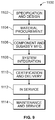
- FIG. 9 is a block diagram of aircraft production and service methodology.
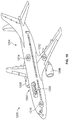
- FIG. 10 is a schematic perspective view of an aircraft.
- Embodiments of the present disclosure provide a dual stripline test fixture that includes a pair of stripline transmission lines or striplines that share a common ground plane.
- a dual stripline test fixture that includes a pair of stripline transmission lines or striplines that share a common ground plane.
- one of the striplines is left empty while another is loaded with the sample, so that baseline data and test sample data may be collected concurrently.
- the overall time for the testing may completed in approximately half the time compared to using a conventional test fixture.
- the test fixture is subjected to half as many temperature cycles over time as the test fixture is used with different samples, improving the lifespan and/or reliability of the test fixture. Accordingly, test times are reduced and cost savings are achieved.
- the test fixture may be mounted on a table that is movably coupled to a rail system with a set of rails that extend up to the first side of an oven and a second set of rails that extend up to the second side of the oven.
- various portions of the test fixture may be moved with respect to the oven to allow different portions of the test fixture to be heated and/or measured, and/or to allow test samples to be added into the test fixture or removed from the test fixture.
- supports may be utilized to support the center conductors of the striplines.
- the interior ends of the supports may be separated by a predetermined distance that defines a testing zone that is sized to enable the sample to be accurately tested.
- the system is motorized and controlled by a computer such that a predetermined test algorithm may be installed on the computer, and the motor operated to move the test fixture along the rails and into the oven. The temperature of the oven and the amount of time that the test fixture is within oven may then be controlled by the controller.
- the algorithm may define a series of temperature steps, with the oven heated in increments and data collected at each desired increment.
- FIG. 1 provides a side view of a dual stripline assembly 100
- FIG. 2 provides a sectional view taken along line 2 - 2 of FIG. 1
- the dual stripline assembly 100 includes a first stripline 110 , a second stripline 120 , and an intermediate member 130 .
- the dual stripline assembly 100 allows for compact, efficient placement of two striplines.
- the dual stripline assembly 100 is configured so that a sample 101 (depicted in phantom lines in FIG.
- first stripline 110 may be positioned in the first stripline 110 , while no sample is positioned in the second stripline 120 , allowing for simultaneous acquisition of test sample signals affected by the sample 101 (from the first stripline 110 ) and baseline or calibration signals not affected by the sample 101 (from the second stripline 120 ), for example with the sample 101 disposed in a heating chamber to test the temperature dependent variability of properties of the sample 101 .
- first stripline 110 will be referred to as being associated with the sample 101
- the second stripline 120 will be referred to as being used for calibration or not being associated with the sample 101 ; however, in other embodiments, the first stripline 110 may be used for calibration and the second stripline 120 used in connection with a test sample.
- the first stripline 110 extends along a length 102 of the dual stripline assembly 100 (e.g., extends generally parallel to a direction corresponding to the length 102 of the dual stripline assembly over at least a portion of the length 102 of the dual stripline assembly 100 ), and includes a first center conductor 112 , a first outer ground plane 114 , and a first inner ground plane 116 .
- the terms “outer” and “inner” are used relative to a central or inner location defined by the intermediate member 130 . Accordingly, the first inner ground plane 116 is closer to the intermediate member 130 than is the first outer ground plane 114 .
- the first center conductor 112 is spaced apart from the first outer ground plane 114 and the first inner ground plane 116 , and is interposed between the first outer ground plane 114 and the first inner ground plane 116 . In the illustrated embodiment, the first center conductor 112 is interposed equidistantly between the first outer ground plane 114 and the first inner ground plane 116 . The depicted first center conductor 112 of the illustrated example is separated from the first outer ground plane 114 and the first inner ground plane 116 by high temperature, low dielectric constant, low loss material at the ends of the stripline and with air in the test zone. Generally, the first stripline 110 provides a planar transmission line.
- a signal may be transmitted via the first stripline 110 and return signals acquired from the first stripline 110 .
- the sample 101 affects the returned and transmitted signals.
- the sample in various embodiments may be understood as being placed in intimate physical contact with the first stripline 110 , with the conductive surfaces of the stripline touching all conductive surfaces of the sample.
- the first center conductor 112 in various embodiments is a flat metal strip.
- the first center conductor 112 has a width 111 , and extends along the length 102 of the assembly.
- the first center conductor 112 may be relatively thin.
- the first center conductor 112 is thinner than the intermediate member 130 .
- the width 111 of the first center conductor 112 is less than the width 113 of the first outer ground plane 114 and the first inner ground plane 116 .
- the depicted sample 101 When placed in the first stripline 110 , the depicted sample 101 generally occupies the space between the first outer ground plane 114 and the first inner ground plane 116 , and is in electrical contact (e.g., intimate electrical contact) with one or more aspects of the first stripline 110 .
- the width of the sample 101 may be the same as or similar to the width 113 of the ground planes. (For example, the nominal width of the sample may be the same as a nominal width of the ground planes, with the widths varying within design and/or manufacturing tolerances). Accordingly, the sample 101 affects signals passing through the first stripline 110 .
- the dual stripline assembly 100 may include a sample mounting fixture and/or mark to facilitate placement of the sample 101 in a predetermined location.
- the sample 101 may include one or more features that cooperate with one or more aspects of the first stripline 110 and/or a sample mounting fixture.
- the sample 101 may have a slot that accepts the first center conductor 112 , allowing the sample 101 to be slid into place from a side of the dual stripline assembly 100 .
- the second stripline 120 extends along the length 102 of the dual stripline assembly 100 .
- the second stripline 120 extends along the length 102 parallel (e.g., parallel within design and/or manufacturing tolerances) to the first stripline 110 .
- the second stripline 120 is configured generally similar to the first stripline 110 .
- the second stripline 120 includes a second center conductor 122 , a second outer ground plane 124 , and a second inner ground plane 126 . As seen in FIGS. 1 and 2 , the second inner ground plane 126 of the depicted second stripline 120 is closer to the intermediate member 130 than the second outer ground plane 124 .
- the second center conductor 122 is spaced apart from the second outer ground plane 124 and the second inner ground plane 126 , and is interposed between the second outer ground plane 124 and the second inner ground plane 126 .
- the second center conductor 122 is interposed equidistantly between the second outer ground plane 124 and the second inner ground plane 126 .
- the second center conductor 122 is separated from the second outer ground plane 124 and the second inner ground plane 126 by a high temperature, low dielectric, low loss material at the ends of the stripline and with air in the test zone.
- the second stripline 120 provides a planar transmission line.
- a signal may be transmitted via the second stripline 120 and the returned and transmitted signals acquired from the second stripline 120 . It may be noted that no sample may be associated with the second stripline 120 in various embodiments. Accordingly, the second stripline 120 may be used to acquire a calibration signal or a baseline signal representing the response of the second stripline 120 (as well as the first stripline 110 which is generally similar to the second stripline 120 ), while the first stripline 110 is used to acquire the test or sample returned and transmitted signals.
- the effect of the sample 101 on the test or sample signals may be separated from a baseline effects provided by the calibration signals thus allowing that portion of the test or sample signals attributable to the sample 101 to be identified.
- first and second striplines may be made of similar materials and similar sizes and shapes so that electrical signals transmitted via the first and second striplines are as similar as practical, allowing an acquired calibration returned and transmitted signals from the second stripline 120 to be treated as a baseline signals for the first stripline 110 (e.g., a signal that would have been acquired from the first stripline 110 if the first stripline 110 did not have the sample 101 associated therewith).
- the second center conductor 122 in various embodiments is a flat metal strip.
- the second center conductor 122 in the illustrated embodiment has the same width 111 as the first center conductor 112 , and also extends along the length 102 of the assembly.
- the nominal width of the second center conductor 122 may be the same as a nominal width of the first center conductor 112 , with the widths varying within design and/or manufacturing tolerances).
- the second center conductor 122 may be relatively thin.
- the first center conductor 112 and the second center conductor may have the same thickness and be thinner than the intermediate member 130 .
- the width of the second outer ground plane 124 and second inner ground plane 126 may be the same width (e.g., with 113 ) as the first outer ground plane 114 and the first inner ground plane 116 .
- the nominal width of the second ground planes may be the same as a nominal width of the first ground planes, with the widths varying within design and/or manufacturing tolerances).
- the depicted intermediate member 130 extends along the length 102 of the dual stripline assembly 100 . As seen in FIGS. 1 and 2 , the intermediate member 130 of the illustrated example extends parallel to the first center conductor 112 and the second center conductor 122 along the entirety of the length 102 of the dual stripline assembly 100 , and is interposed between the first center conductor 112 and the second center conductor 122 .
- the width of the intermediate member 130 in the illustrated embodiment is the width 113 (e.g., the width of the ground planes and the sample, or within design and/or manufacturing tolerances of the width of the ground planes and the sample).
- the intermediate member 130 includes both the first inner ground plane 116 and the second inner ground plane 126 .
- both striplines are provided in various embodiments in a more compact and/or more uniform arrangement than would be provided by two separate striplines (which would require two separate ground planes each or a total of four ground plane structures). Accordingly, both striplines may be utilized in a more compact environment. For example, both striplines may be placed simultaneously in a heating chamber or kiln to save time otherwise required for a calibration measurement, while minimizing the volume of the heating chamber required, thereby providing for easier, quicker, and more cost efficient heating.
- the first stripline 110 and the second stripline 120 are arranged in a vertical or stacked arrangement, with the first stripline 110 above the second stripline 120 .
- Such an arrangement provides for convenient placing of the sample 101 , which, for example, may be supported at least in part by the intermediate member 130 .
- Other arrangements may be utilized in other embodiments.
- the dual stripline assembly 100 may be rotated 90 degrees so that the first stripline 110 and the second stripline 120 are in a side-by-side or horizontal arrangement, with a separate fixture or structure used to support the sample 101 .
- the intermediate member 130 includes both the first inner ground plane 116 and the second inner ground plane 126 .
- the first inner ground plane 116 and the second inner ground plane 126 may be disposed on separate surfaces of the intermediate member 130 .
- the intermediate member 130 includes or is configured as an inner plate 132 .
- the inner plate 132 has a first surface 134 and a second surface 136 , with the second surface 136 opposite the first surface 134 .
- the intermediate portion 130 has an internal portion 135 interposed between the first surface 134 and the second surface 136 .
- the first surface 134 is oriented toward the first center conductor 112
- the second surface 136 is oriented toward the second center conductor 122 .
- the first inner ground plane is disposed on the first surface 134
- the second inner ground plane 126 is disposed on the second surface 136 .
- the intermediate member 130 may be made of a material (e.g., metal) that is relatively highly electrically conductive (to provide for electrical conductivity of the ground planes) while having a relatively low thermal conductivity.
- the dual stripline assembly includes a first outer plate 140 and a second outer plate 150 .
- the depicted first outer plate 140 and second outer plate 150 have the same width 113 as the intermediate member 130 .
- the first outer plate 140 and the second outer plate 150 may be constructed from the same material as the intermediate member 130 .
- the first outer plate 140 has a first inner surface 142 that is oriented toward the first center conductor 112 and the intermediate member 130 , with the first center conductor 112 interposed between the first outer plate 140 and the intermediate member 130 .
- the first outer ground plane 114 of the first stripline 110 is disposed on the first inner surface 142 of the first outer plate 140 .
- the second outer plate 150 may be configured generally similarly to the first outer plate 140 (e.g., similar material, similar dimensions).
- the depicted second outer plate 150 has a second inner surface 152 that is oriented toward the second central conductor 122 and the intermediate member 130 , with the second center conductor 122 interposed between the second outer plate 150 and the intermediate member 130 .
- the second outer ground plane 124 of the second stripline 120 is disposed on the second inner surface 152 of the second outer plate 150 .
- the first outer plate 140 and second outer plate 150 provide structural support and rigidity for the dual stripline assembly 100 in addition to providing the surfaces utilized for the outer ground planes.
- Various embodiments utilize one or more end plates to join the intermediate member 130 and outer plates 140 , 150 .
- the end plates may also be used to place various aspects of the striplines in electrical contact with each other (e.g., to electrically connect corresponding ground planes).
- the end plates like the intermediate member and outer plates, may be made of a metal having relatively high electrical conductivity and relatively low thermal conductivity.
- the dual stripline assembly 100 includes end plates 160 and 168 which are coupled to the intermediate member 130 , first outer plate 140 , and second outer plate 150 .
- the end plates 160 , 168 , intermediate member 130 , first outer plate 140 , and second outer plate may be joined by fasteners.
- the dual stripline assembly 100 also includes a first signal port 162 mounted to the end plate 160 and a second signal port 163 mounted to the end plate 168 , with the first signal port 162 and the second signal port 163 electrically coupled to the first center conductor 112 . Further, the dual stripline assembly 100 also includes a third signal port 164 mounted to the end plate 160 and a fourth signal port 165 mounted to the end plate 168 , with the third signal port 164 and fourth signal port 165 electrically coupled to the second center conductor 122 .
- the signal ports provide for convenient coupling of the center conductors with wires for providing transmitted signals to be sent through the striplines and to acquire returned signals from the striplines.
- a test sample signal may be sent to the first stripline 110 , and a test sample return signal acquired from the first stripline 110 , via the first signal port 162 , and a transmitted signal acquired from the first stripline 110 via the second signal port 163 .
- a calibration signal may be sent to the second stripline 120 , and a calibration return signal acquired from the second stripline 120 , via the third signal port 164 , and a transmitted signal acquired from the second stripline 120 via the fourth signal port 165 .
- the dual stripline assembly 100 includes buffer zones 105 , a test zone 107 and a loading zone 109 .
- the buffer zones 105 are disposed proximate the end plates 160 and 168 .
- the buffer zones 105 extend from the end plates 160 and 168 toward the interior of the dual stripline assembly 100 until a border with the loading zone 109 is reached.
- the test zone 107 is centered within the loading zone 109 and is configured to receive the sample 101 .
- the test zone 107 may include a marker for locating the sample 101 and/or a fixture for securing the sample 101 in a predetermined desired location, providing for consistent, uniform placement of samples in the dual stripline assembly 100 , helping to provide consistency of test conditions for different samples tested at different times.
- the buffer zone 105 is outside of the heating chamber.
- the buffer zones 105 are configured to protect electrical components (e.g., signal ports and/or associated cabling) from becoming overly heated when the test zone 107 is heated.
- the length of the buffer zones 105 in connection with the low thermal conductivity of the various structural members (e.g., first outer plate 140 , intermediate member 130 , second outer plate 150 , end plate 160 ) prevents the electronics associated with or mounted to the end plate 160 (e.g., first and third signal ports 162 and 164 and the associated cabling), and the electronics associated with or mounted to the end plate 168 (e.g., second and fourth signal ports 163 and 165 and the associated cabling) from becoming overly heated via conductive heating from the test zone 107 being heated.
- the various structural members e.g., first outer plate 140 , intermediate member 130 , second outer plate 150 , end plate 160 .
- the test zone 107 is interposed (in the illustrated embodiment, interposed equidistantly) between the two buffer zones 105 , with the buffer zone 105 adjacent to end plate 168 disposed in the heating chamber when the loading zone 109 and the test zone 107 are retracted from the heating chamber (e.g., for changing test samples).
- the center conductors are made of thin metal strips. As such, as the length of the center conductors increase due to heating, they become increasingly subject to bowing or flexing under their own weight, or, in the case of the first center conductor 112 of the illustrated embodiment, potentially under any additional force caused by the sample 101 , depending on how the sample 101 is coupled to the first central conductor 112 . Accordingly, in various embodiments, the dual stripline assembly 100 includes supports that are configured to be interposed between the center conductors and the corresponding ground planes. The supports may be made of a ceramic or other high temperature material that is electrically insulating.
- FIG. 3 provides a side view of an embodiment of the dual stripline assembly 100 including end supports 300 .
- a first end support 302 is interposed between the first center conductor 112 and the first outer ground plane 114
- a second end support 304 is interposed between the first center conductor 112 and the first inner ground plane 116 (which is disposed on the intermediate member 130 ).
- a third end support 306 is interposed between the second center conductor 122 and the second inner ground plane 126 (which is disposed on the intermediate member 130 )
- a fourth end support is interposed between the second center conductor 122 and the second outer ground plane 124 .
- end supports 300 are sized to provided support to the center conductors by filling the space between the center conductors and the corresponding ground planes to help maintain the center conductors at or near parallel to the ground planes. While the end supports 300 are depicted in FIG. 3 as being positioned near the end plate 160 for ease of illustration, it may be noted that additional end supports 300 may be positioned proximate the opposite end of the dual stripline assembly 100 as well.
- FIG. 4 provides a side view of supports 400 configured to be used at one or more intermediate locations (e.g., away from the ends) of the dual stripline assembly
- FIG. 5 provides an overhead view of supports 400 formed in accordance with various embodiments. Similar to the supports 300 , the supports 400 are configured to be interposed between the center conductors and corresponding ground planes, and provide support to help maintain the center conductors at or near parallel to the ground planes.
- the supports 400 of the depicted example include a tapered support 402 (e.g., some or all of the intermediately positioned supports 400 may be configured as a tapered support 402 ).
- the tapered support 402 has a width that varies along the length 102 of the dual stripline assembly 100 .
- the depicted tapered support 402 has a maximum width 406 that corresponds to the width 111 of the first center conductor 112 and second center conductor 122 (for example, the maximum width 406 is the same as or less than the width 111 ; or, as another example, the maximum width 406 is the same as the width 111 within design and/or manufacturing tolerances).
- the tapered support 402 increases width from a leading edge 408 until the maximum width 406 is reached at a central axis 409 , with width decreasing from the maximum width 406 at the central axis 409 toward the trailing edge 410 .
- the tapered support 402 is symmetrical about the central axis 409 , with the rate of increase or decrease from each leading edge toward the central axis 409 being the same.
- the tapering of the tapered support 402 along the length 102 in various embodiments helps reduce reflections of the signals as they travel along the striplines 110 and 120 and helps allow electromagnetic propagation.
- the intermediate supports 400 may be positioned a predetermined distance from the sample 101 so as not to interact with the sample 101 and to minimize or reduce the effect on electromagnetic propagation near the sample 101 .
- the dual stripline assembly 100 may be used as part of a testing system that includes additional components.
- FIGS. 6 and 7 illustrates a testing system 600 that includes a test fixture such as the dual stripline test assembly 100 (or similar fixture), a heating chamber 610 , rails 620 , and a processing unit 630 .
- the testing system 600 is configured to move the test zone 107 of the dual stripline assembly 100 into and out of the heating chamber 610 to test the temperature variability of the EM properties (e.g., permittivity and permeability) of a sample 101 disposed within the test zone 107 .
- the test zone 107 is out of the heating chamber 610 in FIG. 6 (e.g., for loading or unloading a sample 101 in the test zone 107 ), and the test zone 107 is in the heating chamber 610 in FIG. 7 .
- the heating chamber 610 is an oven or kiln configured to heat the sample 101 .
- the amount of heat provided by the heating chamber 610 may be controlled by the processing unit 630 .
- the temperature of the heating chamber 610 may be incrementally controlled in a series of steps, for example, to allow the sample 101 to reach a series of stable temperatures, with measurements taken at each stable temperature used to determine the temperature variability of the EM properties of the sample 101 .
- the rails 620 in the illustrated embodiment are positioned on either side and adjacent to heating chamber 610 , and are configured to support the dual stripline assembly 100 (or similar dual stripline test fixture).
- carriages 622 may be mounted to the dual stripline test assembly 100 , with the carriages 622 configured to translate along the rails 620 while supporting the dual stripline test assembly.
- the carriages 622 may include wheels that roll along the rails 620 or guides that slide along the rails.
- a motor 624 or other motive device or actuator e.g., cylinder or other linear actuator
- the processing unit 630 may be mounted in various embodiments to one or more of the carriages 622 , and controlled by the processing unit 630 , to provide automated translation of the dual stripline assembly 100 .
- the test zone 107 of the dual stripline assembly 100 may be advanced into the heating chamber 610 .
- the processing unit 630 is operably coupled to the heating chamber 610 and to the dual stripline assembly 100 .
- the processing unit 630 is configured (e.g., programmed) to control the heating chamber 610 .
- the processing unit 630 is configured to provide a first signal 650 (e.g., a test sample input signal) to the first stripline 110 and receive a returned signal 652 from the first stripline 110 , and to provide a second signal 660 (e.g., a calibration input signal) to the second stripline and receive a returned signal 662 from the second stripline 120 .
- a first signal 650 e.g., a test sample input signal
- a second signal 660 e.g., a calibration input signal
- the processing unit 630 is also configured to acquire a sample response transmitted signal 653 from the first stripline 110 and to acquire a calibration response transmitted signal 663 from the second stripline 120 .
- the processing unit 630 analyzes the acquired signals to determine the EM properties of the sample 101 at the selected measurement temperatures.
- additional sensors e.g., temperature sensors
- sample response signals and calibration response signals may be acquired at each temperature, and used to determine the variation of properties of the sample 101 with changed in temperature.
- the processing unit 630 sends test signals and receives test returned and transmitted signals from the first stripline 110 to determine scattering parameters of first stripline 110 with the sample 101 associated therewith.
- the processing unit 630 sends calibration signals and receives calibration returned and transmitted signals to determine scattering parameters of the second stripline 120 without sample 101 associated therewith at the same temperatures.
- the processing unit 630 can use the temperature variability of the calibration signal to remove the effect of the stripline assembly on the signals received from the first stripline 110 with the sample 101 , and to accordingly obtain the temperature variability of EM properties of the sample 101 with effects from the stripline structures removed. Because the first and second stripline are in the heating chamber 610 at the same time, consistent temperatures are used for both the test and calibration signals, and the amount of time is greatly reduced (e.g., cut in half or more) by removing the need for a separate calibration heating process that would be required if only one stripline were used.
- processing unit 630 may include multiple physical units or devices in various embodiments.
- a heating controller e.g., function generator
- signal analyzer may be disposed in a separate unit from other aspects of the processing unit 630 .
- the processing unit 630 includes processing circuitry configured to perform one or more tasks, functions, or steps discussed herein.
- processing unit as used herein is not intended to necessarily be limited to a single processor or computer.
- the processing unit 630 may include multiple processors, ASIC's, FPGA's, and/or computers, which may be integrated in a common housing or unit, or which may distributed among various units or housings.
- operations performed by the processing unit 630 e.g., operations corresponding to process flows or methods discussed herein, or aspects thereof
- the processing unit 630 includes a tangible, non-transitory memory 632 for storage of, among other things, instructions for causing the processing unit 630 to perform one or more steps or tasks discussed herein.
- the memory 632 may also store, for example, acquired signals (e.g., test sample return signals and calibration return signals) use for further processing or analysis and/or the results of the processing or analysis of the acquired signals (e.g., results describing the temperature variability of the sample 101 ).
- the depicted system 600 also includes a display unit 640 coupled to the processing unit 630 , which may be used to display test results (e.g., via a display on a screen and/or a printed display).
- FIG. 8 illustrates a flowchart of a method 800 .
- the operations of FIG. 8 may be implemented by one or more processors (e.g., processing unit 630 ) executing program instructions stored in memory (e.g., memory 632 ).
- the method 800 may employ structures or aspects of various embodiments (e.g., systems and/or methods) discussed herein, such as the system 600 .
- certain steps (or operations) may be omitted or added, certain steps may be combined, certain steps may be performed simultaneously, certain steps may be performed concurrently, certain steps may be split into multiple steps, certain steps may be performed in a different order, or certain steps or series of steps may be re-performed in an iterative fashion.
- portions, aspects, and/or variations of the method 800 may be used as one or more algorithms to direct hardware to perform one or more operations described herein. It should be noted, other methods may be used, in accordance with embodiments herein.
- a dual stripline test fixture (e.g., dual stripline assembly 100 ) is provided.
- the dual stripline test fixture includes two striplines sharing a common ground plane as discussed herein. Accordingly, the dual stripline assembly provides a compact test fixture that allows both a calibration stripline and a test sample stripline to be simultaneously measured while reducing the size requirement for an oven heating the sample.
- a sample is placed in electrical contact with a first stripline (e.g., stripline 110 ) in a test zone (e.g., test zone 107 ) of the dual stripline test fixture. It may be noted that no sample is associated with a second stripline (e.g., stripline 120 ), allowing the first stripline to be used to test the sample and the second stripline used to obtain calibration or baseline results for identifying and removing effects of the stripline on the results obtained for the sample.
- a first stripline e.g., stripline 110
- test zone e.g., test zone 107
- supports are positioned between the central conductors and the corresponding ground planes of the dual stripline test fixture.
- the supports may include tapered supports (e.g., tapered supports 402 described in connection with FIGS. 4 and 5 herein).
- a marking feature is used to place the sample. Use of a marking feature helps provide consistent placement of different samples in the same location of the test zone 107 .
- the marking feature may include a fixture that is physically coupled to the sample and helps secure the sample in a desired location.
- the test zone of the dual stripline test fixture (with the sample in place) is advanced into a heating chamber (e.g., heating chamber 610 ).
- a heating chamber e.g., heating chamber 610
- the dual stripline test fixture may be disposed on a track (e.g., including rails 620 ), and the dual stripline test fixture may be advanced on the track to position the test zone in the heating chamber.
- the sample is heated with the heating chamber.
- the sample may be heated in a series of steps, allowing measurements to be taken at discrete, known temperatures as the sample is heated progressively to higher and higher temperatures.
- a first signal is provided to the first stripline
- a second signal is provided to the second stripline.
- the signals for example may have a known or predetermined waveform, and be transmitted along the first and second striplines.
- the first signal traverses the first stripline
- the first signal is affected by the sample associated with the first stripline.
- the second signal traverses the second stripline, there is no sample to affect the second signal.
- the first signal may be referred to as a test or sample signal
- the second signal referred to as a calibration or baseline signal.
- sample response signals e.g., a sample returned signal and a sample transmitted signal
- calibration response signals e.g., a calibration returned signal and calibration transmitted signal
- the signals of 814 and 816 may be sent (and the signals of 818 and 820 acquired) at incremental time intervals corresponding to incremental steps at which the sample is heated. Accordingly, a series of sample response signals and corresponding calibration response signals may be correlated with particular temperatures.
- temperature variability of properties e.g., EM properties such as permittivity and permeability
- scattering parameters may be measured using the signals acquired at 818 and 820 , and used to evaluate temperature response of the sample.
- the calibration and sample signals are compared to isolate aspects of the measurements attributable to the sample with effects of the stripline removed to determine the properties of the sample.
- illustrative method 1100 may include specification and design 1102 of the aircraft 1200 and material procurement 1104 .
- component and subassembly manufacturing 1106 and system integration 1108 of the aircraft 1200 take place.
- the aircraft 1200 may go through certification and delivery 1110 to be placed in service 1112 .
- routine maintenance and service 1114 which may also include modification, reconfiguration, refurbishment, and so on).
- Each of the processes of the illustrative method 1100 may be performed or carried out by a system integrator, a third party, and/or an operator (e.g., a customer).
- a system integrator may include, without limitation, any number of aircraft manufacturers and major-system subcontractors
- a third party may include, without limitation, any number of vendors, subcontractors, and suppliers
- an operator may be an airline, leasing company, military entity, service organization, and so on.
- the aircraft 1200 produced by the illustrative method 1100 may include an airframe 1202 with a plurality of high-level systems 1204 and an interior 1206 .
- high-level systems 1204 include one or more of a propulsion system 1208 , an electrical system 1210 , a hydraulic system 1212 , and an environmental system 1214 . Any number of other systems may be included.
- an aerospace example is shown, the principles of the invention may be applied to other industries, such as the automotive industry. Accordingly, in addition to aircraft 1200 , the principles disclosed herein may apply to other vehicles, e.g., land vehicles, marine vehicles, space vehicles, etc.
- Apparatus and methods shown or described herein may be employed during any one or more of the stages of the manufacturing and service method 1100 .
- components or subassemblies corresponding to component and subassembly manufacturing 1106 may be fabricated or manufactured in a manner similar to components or subassemblies produced while the aircraft 1200 is in service.
- one or more aspects of the apparatus, method, or combination thereof may be utilized during the production stages 1106 and 1108 , for example, by substantially expediting assembly of or reducing the cost of an aircraft 1200 .
- one or more aspects of the apparatus or method realizations, or a combination thereof may be utilized, for example and without limitation, while the aircraft 1200 is in service, e.g., maintenance and service 1114 .
- control unit central processing unit
- unit CPU
- CPU central processing unit
- ASIC application specific integrated circuits
- a processing unit may be or include one or more processors that are configured to perform various tasks or operations described herein.
- the processing unit 630 may be configured to execute a set of instructions that are stored in one or more data storage units or elements (such as one or more memories such as memory 632 ), in order to process data.
- the data storage units may also store data or other information as desired or needed.
- the data storage units may be in the form of an information source or a physical memory element within a processing machine.
- the set of instructions may include various commands that instruct the processing unit 630 as a processing machine to perform specific operations such as the methods and processes of the various embodiments of the subject matter described herein.
- the set of instructions may be in the form of a software program.
- the software may be in various forms such as system software or application software. Further, the software may be in the form of a collection of separate programs, a program subset within a larger program or a portion of a program.
- the software may also include modular programming in the form of object-oriented programming.
- the processing of input data by the processing machine may be in response to user commands, or in response to results of previous processing, or in response to a request made by another processing machine.
- the diagrams of embodiments herein illustrate one or more control or processing units, such as the processing unit 630 .
- the processing or control units may represent circuits, circuitry, or portions thereof that may be implemented as hardware with associated instructions (e.g., software stored on a tangible and non-transitory computer readable storage medium, such as a computer hard drive, ROM, RAM, or the like) that perform the operations described herein.
- the hardware may include state machine circuitry hardwired to perform the functions described herein.
- the hardware may include electronic circuits that include and/or are connected to one or more logic-based devices, such as microprocessors, processors, controllers, or the like.
- the circuits in various embodiments may be configured to execute one or more algorithms to perform functions described herein.
- the one or more algorithms may include aspects of embodiments disclosed herein, whether or not expressly identified in a flowchart or a method.
- the terms “software” and “firmware” are interchangeable, and include any computer program stored in a data storage unit (for example, one or more memories) for execution by a computer, including RAM memory, ROM memory, EPROM memory, EEPROM memory, and non-volatile RAM (NVRAM) memory.
- a data storage unit for example, one or more memories
- NVRAM non-volatile RAM
- the above data storage unit types are exemplary only, and are thus not limiting as to the types of memory usable for storage of a computer program.
- a structure, limitation, or element that is “configured to” perform a task or operation is particularly structurally formed, constructed, or adapted in a manner corresponding to the task or operation.
- an object that is merely capable of being modified to perform the task or operation is not “configured to” perform the task or operation as used herein.
Landscapes
- Physics & Mathematics (AREA)
- General Physics & Mathematics (AREA)
- Engineering & Computer Science (AREA)
- Automation & Control Theory (AREA)
- Manufacturing & Machinery (AREA)
- Investigating Or Analyzing Materials Using Thermal Means (AREA)
Abstract
Description
Claims (20)
Priority Applications (1)
| Application Number | Priority Date | Filing Date | Title |
|---|---|---|---|
| US15/956,417 US10634700B2 (en) | 2018-04-18 | 2018-04-18 | Dual stripline test fixture apparatuses and methods |
Applications Claiming Priority (1)
| Application Number | Priority Date | Filing Date | Title |
|---|---|---|---|
| US15/956,417 US10634700B2 (en) | 2018-04-18 | 2018-04-18 | Dual stripline test fixture apparatuses and methods |
Publications (2)
| Publication Number | Publication Date |
|---|---|
| US20190324059A1 US20190324059A1 (en) | 2019-10-24 |
| US10634700B2 true US10634700B2 (en) | 2020-04-28 |
Family
ID=68236327
Family Applications (1)
| Application Number | Title | Priority Date | Filing Date |
|---|---|---|---|
| US15/956,417 Active 2038-06-29 US10634700B2 (en) | 2018-04-18 | 2018-04-18 | Dual stripline test fixture apparatuses and methods |
Country Status (1)
| Country | Link |
|---|---|
| US (1) | US10634700B2 (en) |
Citations (5)
| Publication number | Priority date | Publication date | Assignee | Title |
|---|---|---|---|---|
| US4538124A (en) * | 1984-02-10 | 1985-08-27 | Rca Corporation | Planar microwave circuit component mounting system |
| JPH0344307A (en) * | 1989-07-12 | 1991-02-26 | Onoda Autoclaved Light Weight Concrete Co Ltd | Controlling method of fish poison plankton |
| US5351001A (en) * | 1990-04-05 | 1994-09-27 | General Electric Company | Microwave component test method and apparatus |
| US8058557B2 (en) * | 2007-09-06 | 2011-11-15 | Hon Hai Precision Industry Co., Ltd. | Printed circuit board |
| US20170077578A1 (en) * | 2014-06-02 | 2017-03-16 | Murata Manufacturing Co., Ltd. | Transmission line |
-
2018
- 2018-04-18 US US15/956,417 patent/US10634700B2/en active Active
Patent Citations (5)
| Publication number | Priority date | Publication date | Assignee | Title |
|---|---|---|---|---|
| US4538124A (en) * | 1984-02-10 | 1985-08-27 | Rca Corporation | Planar microwave circuit component mounting system |
| JPH0344307A (en) * | 1989-07-12 | 1991-02-26 | Onoda Autoclaved Light Weight Concrete Co Ltd | Controlling method of fish poison plankton |
| US5351001A (en) * | 1990-04-05 | 1994-09-27 | General Electric Company | Microwave component test method and apparatus |
| US8058557B2 (en) * | 2007-09-06 | 2011-11-15 | Hon Hai Precision Industry Co., Ltd. | Printed circuit board |
| US20170077578A1 (en) * | 2014-06-02 | 2017-03-16 | Murata Manufacturing Co., Ltd. | Transmission line |
Non-Patent Citations (1)
| Title |
|---|
| Bogle et al., "High-Temperature RF Material Characterization Using a Dual-Chambered Rectangular Waveguide Fixture", IEEE Transactions on Instrumentation and Measurement, Sep. 2017, vol. 66, No. 9, 6 pages. |
Also Published As
| Publication number | Publication date |
|---|---|
| US20190324059A1 (en) | 2019-10-24 |
Similar Documents
| Publication | Publication Date | Title |
|---|---|---|
| US11747304B2 (en) | In-process quality assessment for additive manufacturing | |
| US8791707B2 (en) | Concentric coplanar capacitive sensor system with quantitative model | |
| CN109642862B (en) | Integrated system and method for in-situ 3-axis scanning and detecting defects in objects under static and cyclic testing | |
| CN110375686B (en) | Wireless Flexible Microstrip Patch Antenna Sensor Array for Crack and Strain Monitoring in Metal Structures | |
| CN108061516B (en) | Combined surface inspection using multiple scanners | |
| DE102014116497B4 (en) | Method and use of a device for measuring the local effective permittivity of electrically non-conductive or weakly conductive materials | |
| US7479790B2 (en) | Capacitive plate dielectrometer method and system for measuring dielectric properties | |
| US20180172521A1 (en) | Systems and methods for measuring surface temperature | |
| Hyde et al. | A broadband, nondestructive microwave sensor for characterizing magnetic sheet materials | |
| US10634700B2 (en) | Dual stripline test fixture apparatuses and methods | |
| CN103472304A (en) | Elastic probe array multi-channel resistance measurement method and device | |
| US9599576B1 (en) | Acoustic—RF multi-sensor material characterization system | |
| EP2530020B1 (en) | Aircraft fuselage inspection system | |
| CN113008940B (en) | Method and apparatus for detecting layer inconsistencies within a complex. | |
| CN204988097U (en) | Utensil and car are examined to door decorative board | |
| Berger et al. | Conception of an eddy current in-process quality control for the production of carbon fibre reinforced components in the RTM process chain | |
| KR101523531B1 (en) | Non-contact flatness inspection apparatus and inspection method | |
| US20160356735A1 (en) | Nondestructive tester | |
| US11268931B2 (en) | Segmented field eddy current sensing for dispersive property measurement and complex structures | |
| CN106501617B (en) | Calibration method of dielectric material measurement piece, short circuit calibration piece, dielectric material measurement method and device | |
| Hyde IV et al. | Nondestructive characterization of Salisbury screen and Jaumann absorbers using a clamped rectangular waveguide geometry | |
| Samolej et al. | Radio-frequency sensor for non-destructive evaluation of composite materials | |
| US20090199652A1 (en) | Tensile specimen measuring apparatus and method | |
| Suresh et al. | In-situ surface crack detection on metal using a passive wireless RFID-based NDT sensor | |
| Ćenanović et al. | Measurement setup for non-destructive complex permittivity determination of solid materials using two coupled coaxial probes |
Legal Events
| Date | Code | Title | Description |
|---|---|---|---|
| AS | Assignment |
Owner name: THE BOEING COMPANY, ILLINOIS Free format text: ASSIGNMENT OF ASSIGNORS INTEREST;ASSIGNORS:FRASCH, LYDELL L.;ROMAN, NATHANIEL PHILIP;REEL/FRAME:045578/0820 Effective date: 20180417 |
|
| FEPP | Fee payment procedure |
Free format text: ENTITY STATUS SET TO UNDISCOUNTED (ORIGINAL EVENT CODE: BIG.); ENTITY STATUS OF PATENT OWNER: LARGE ENTITY |
|
| STPP | Information on status: patent application and granting procedure in general |
Free format text: RESPONSE TO NON-FINAL OFFICE ACTION ENTERED AND FORWARDED TO EXAMINER |
|
| STPP | Information on status: patent application and granting procedure in general |
Free format text: FINAL REJECTION MAILED |
|
| STPP | Information on status: patent application and granting procedure in general |
Free format text: RESPONSE AFTER FINAL ACTION FORWARDED TO EXAMINER |
|
| STPP | Information on status: patent application and granting procedure in general |
Free format text: NOTICE OF ALLOWANCE MAILED -- APPLICATION RECEIVED IN OFFICE OF PUBLICATIONS |
|
| STCF | Information on status: patent grant |
Free format text: PATENTED CASE |
|
| MAFP | Maintenance fee payment |
Free format text: PAYMENT OF MAINTENANCE FEE, 4TH YEAR, LARGE ENTITY (ORIGINAL EVENT CODE: M1551); ENTITY STATUS OF PATENT OWNER: LARGE ENTITY Year of fee payment: 4 |