US10634200B2 - Control of a powertrain backlash - Google Patents
Control of a powertrain backlash Download PDFInfo
- Publication number
- US10634200B2 US10634200B2 US16/091,367 US201716091367A US10634200B2 US 10634200 B2 US10634200 B2 US 10634200B2 US 201716091367 A US201716091367 A US 201716091367A US 10634200 B2 US10634200 B2 US 10634200B2
- Authority
- US
- United States
- Prior art keywords
- clutch
- backlash
- torque
- powertrain
- rotational speed
- Prior art date
- Legal status (The legal status is an assumption and is not a legal conclusion. Google has not performed a legal analysis and makes no representation as to the accuracy of the status listed.)
- Active
Links
- 238000000034 method Methods 0.000 claims abstract description 32
- 230000008859 change Effects 0.000 claims abstract description 29
- 238000012546 transfer Methods 0.000 claims abstract description 9
- 238000004590 computer program Methods 0.000 claims description 12
- 230000007935 neutral effect Effects 0.000 claims description 6
- 230000001419 dependent effect Effects 0.000 claims description 4
- 230000010355 oscillation Effects 0.000 description 16
- 230000005540 biological transmission Effects 0.000 description 9
- 238000003379 elimination reaction Methods 0.000 description 6
- 230000001133 acceleration Effects 0.000 description 5
- 230000008030 elimination Effects 0.000 description 5
- 230000008878 coupling Effects 0.000 description 4
- 238000010168 coupling process Methods 0.000 description 4
- 238000005859 coupling reaction Methods 0.000 description 4
- 238000012795 verification Methods 0.000 description 3
- 238000004891 communication Methods 0.000 description 2
- 230000006870 function Effects 0.000 description 2
- 230000001360 synchronised effect Effects 0.000 description 2
- 230000004913 activation Effects 0.000 description 1
- 238000002485 combustion reaction Methods 0.000 description 1
- 230000009849 deactivation Effects 0.000 description 1
- 230000000694 effects Effects 0.000 description 1
- 238000012545 processing Methods 0.000 description 1
- 230000009467 reduction Effects 0.000 description 1
- 239000011435 rock Substances 0.000 description 1
- 230000007704 transition Effects 0.000 description 1
- 238000004804 winding Methods 0.000 description 1
Images


Classifications
-
- F—MECHANICAL ENGINEERING; LIGHTING; HEATING; WEAPONS; BLASTING
- F16—ENGINEERING ELEMENTS AND UNITS; GENERAL MEASURES FOR PRODUCING AND MAINTAINING EFFECTIVE FUNCTIONING OF MACHINES OR INSTALLATIONS; THERMAL INSULATION IN GENERAL
- F16D—COUPLINGS FOR TRANSMITTING ROTATION; CLUTCHES; BRAKES
- F16D48/00—External control of clutches
- F16D48/06—Control by electric or electronic means, e.g. of fluid pressure
-
- B—PERFORMING OPERATIONS; TRANSPORTING
- B60—VEHICLES IN GENERAL
- B60W—CONJOINT CONTROL OF VEHICLE SUB-UNITS OF DIFFERENT TYPE OR DIFFERENT FUNCTION; CONTROL SYSTEMS SPECIALLY ADAPTED FOR HYBRID VEHICLES; ROAD VEHICLE DRIVE CONTROL SYSTEMS FOR PURPOSES NOT RELATED TO THE CONTROL OF A PARTICULAR SUB-UNIT
- B60W10/00—Conjoint control of vehicle sub-units of different type or different function
- B60W10/02—Conjoint control of vehicle sub-units of different type or different function including control of driveline clutches
-
- B—PERFORMING OPERATIONS; TRANSPORTING
- B60—VEHICLES IN GENERAL
- B60W—CONJOINT CONTROL OF VEHICLE SUB-UNITS OF DIFFERENT TYPE OR DIFFERENT FUNCTION; CONTROL SYSTEMS SPECIALLY ADAPTED FOR HYBRID VEHICLES; ROAD VEHICLE DRIVE CONTROL SYSTEMS FOR PURPOSES NOT RELATED TO THE CONTROL OF A PARTICULAR SUB-UNIT
- B60W10/00—Conjoint control of vehicle sub-units of different type or different function
- B60W10/10—Conjoint control of vehicle sub-units of different type or different function including control of change-speed gearings
- B60W10/11—Stepped gearings
-
- B—PERFORMING OPERATIONS; TRANSPORTING
- B60—VEHICLES IN GENERAL
- B60W—CONJOINT CONTROL OF VEHICLE SUB-UNITS OF DIFFERENT TYPE OR DIFFERENT FUNCTION; CONTROL SYSTEMS SPECIALLY ADAPTED FOR HYBRID VEHICLES; ROAD VEHICLE DRIVE CONTROL SYSTEMS FOR PURPOSES NOT RELATED TO THE CONTROL OF A PARTICULAR SUB-UNIT
- B60W10/00—Conjoint control of vehicle sub-units of different type or different function
- B60W10/18—Conjoint control of vehicle sub-units of different type or different function including control of braking systems
- B60W10/196—Conjoint control of vehicle sub-units of different type or different function including control of braking systems acting within the driveline, e.g. retarders
-
- B—PERFORMING OPERATIONS; TRANSPORTING
- B60—VEHICLES IN GENERAL
- B60W—CONJOINT CONTROL OF VEHICLE SUB-UNITS OF DIFFERENT TYPE OR DIFFERENT FUNCTION; CONTROL SYSTEMS SPECIALLY ADAPTED FOR HYBRID VEHICLES; ROAD VEHICLE DRIVE CONTROL SYSTEMS FOR PURPOSES NOT RELATED TO THE CONTROL OF A PARTICULAR SUB-UNIT
- B60W30/00—Purposes of road vehicle drive control systems not related to the control of a particular sub-unit, e.g. of systems using conjoint control of vehicle sub-units
- B60W30/18—Propelling the vehicle
- B60W30/184—Preventing damage resulting from overload or excessive wear of the driveline
-
- B—PERFORMING OPERATIONS; TRANSPORTING
- B60—VEHICLES IN GENERAL
- B60W—CONJOINT CONTROL OF VEHICLE SUB-UNITS OF DIFFERENT TYPE OR DIFFERENT FUNCTION; CONTROL SYSTEMS SPECIALLY ADAPTED FOR HYBRID VEHICLES; ROAD VEHICLE DRIVE CONTROL SYSTEMS FOR PURPOSES NOT RELATED TO THE CONTROL OF A PARTICULAR SUB-UNIT
- B60W30/00—Purposes of road vehicle drive control systems not related to the control of a particular sub-unit, e.g. of systems using conjoint control of vehicle sub-units
- B60W30/18—Propelling the vehicle
- B60W30/19—Improvement of gear change, e.g. by synchronisation or smoothing gear shift
-
- B—PERFORMING OPERATIONS; TRANSPORTING
- B60—VEHICLES IN GENERAL
- B60W—CONJOINT CONTROL OF VEHICLE SUB-UNITS OF DIFFERENT TYPE OR DIFFERENT FUNCTION; CONTROL SYSTEMS SPECIALLY ADAPTED FOR HYBRID VEHICLES; ROAD VEHICLE DRIVE CONTROL SYSTEMS FOR PURPOSES NOT RELATED TO THE CONTROL OF A PARTICULAR SUB-UNIT
- B60W30/00—Purposes of road vehicle drive control systems not related to the control of a particular sub-unit, e.g. of systems using conjoint control of vehicle sub-units
- B60W30/18—Propelling the vehicle
- B60W30/20—Reducing vibrations in the driveline
-
- B—PERFORMING OPERATIONS; TRANSPORTING
- B60—VEHICLES IN GENERAL
- B60W—CONJOINT CONTROL OF VEHICLE SUB-UNITS OF DIFFERENT TYPE OR DIFFERENT FUNCTION; CONTROL SYSTEMS SPECIALLY ADAPTED FOR HYBRID VEHICLES; ROAD VEHICLE DRIVE CONTROL SYSTEMS FOR PURPOSES NOT RELATED TO THE CONTROL OF A PARTICULAR SUB-UNIT
- B60W40/00—Estimation or calculation of non-directly measurable driving parameters for road vehicle drive control systems not related to the control of a particular sub unit, e.g. by using mathematical models
- B60W40/12—Estimation or calculation of non-directly measurable driving parameters for road vehicle drive control systems not related to the control of a particular sub unit, e.g. by using mathematical models related to parameters of the vehicle itself, e.g. tyre models
-
- F—MECHANICAL ENGINEERING; LIGHTING; HEATING; WEAPONS; BLASTING
- F16—ENGINEERING ELEMENTS AND UNITS; GENERAL MEASURES FOR PRODUCING AND MAINTAINING EFFECTIVE FUNCTIONING OF MACHINES OR INSTALLATIONS; THERMAL INSULATION IN GENERAL
- F16H—GEARING
- F16H57/00—General details of gearing
- F16H57/02—Gearboxes; Mounting gearing therein
-
- B—PERFORMING OPERATIONS; TRANSPORTING
- B60—VEHICLES IN GENERAL
- B60W—CONJOINT CONTROL OF VEHICLE SUB-UNITS OF DIFFERENT TYPE OR DIFFERENT FUNCTION; CONTROL SYSTEMS SPECIALLY ADAPTED FOR HYBRID VEHICLES; ROAD VEHICLE DRIVE CONTROL SYSTEMS FOR PURPOSES NOT RELATED TO THE CONTROL OF A PARTICULAR SUB-UNIT
- B60W2510/00—Input parameters relating to a particular sub-units
- B60W2510/02—Clutches
- B60W2510/0208—Clutch engagement state, e.g. engaged or disengaged
-
- B—PERFORMING OPERATIONS; TRANSPORTING
- B60—VEHICLES IN GENERAL
- B60W—CONJOINT CONTROL OF VEHICLE SUB-UNITS OF DIFFERENT TYPE OR DIFFERENT FUNCTION; CONTROL SYSTEMS SPECIALLY ADAPTED FOR HYBRID VEHICLES; ROAD VEHICLE DRIVE CONTROL SYSTEMS FOR PURPOSES NOT RELATED TO THE CONTROL OF A PARTICULAR SUB-UNIT
- B60W2510/00—Input parameters relating to a particular sub-units
- B60W2510/02—Clutches
- B60W2510/0241—Clutch slip, i.e. difference between input and output speeds
- B60W2510/025—Slip change rate
-
- B—PERFORMING OPERATIONS; TRANSPORTING
- B60—VEHICLES IN GENERAL
- B60W—CONJOINT CONTROL OF VEHICLE SUB-UNITS OF DIFFERENT TYPE OR DIFFERENT FUNCTION; CONTROL SYSTEMS SPECIALLY ADAPTED FOR HYBRID VEHICLES; ROAD VEHICLE DRIVE CONTROL SYSTEMS FOR PURPOSES NOT RELATED TO THE CONTROL OF A PARTICULAR SUB-UNIT
- B60W2510/00—Input parameters relating to a particular sub-units
- B60W2510/02—Clutches
- B60W2510/0266—Moment of inertia
-
- B—PERFORMING OPERATIONS; TRANSPORTING
- B60—VEHICLES IN GENERAL
- B60W—CONJOINT CONTROL OF VEHICLE SUB-UNITS OF DIFFERENT TYPE OR DIFFERENT FUNCTION; CONTROL SYSTEMS SPECIALLY ADAPTED FOR HYBRID VEHICLES; ROAD VEHICLE DRIVE CONTROL SYSTEMS FOR PURPOSES NOT RELATED TO THE CONTROL OF A PARTICULAR SUB-UNIT
- B60W2510/00—Input parameters relating to a particular sub-units
- B60W2510/02—Clutches
- B60W2510/0275—Clutch torque
-
- B—PERFORMING OPERATIONS; TRANSPORTING
- B60—VEHICLES IN GENERAL
- B60W—CONJOINT CONTROL OF VEHICLE SUB-UNITS OF DIFFERENT TYPE OR DIFFERENT FUNCTION; CONTROL SYSTEMS SPECIALLY ADAPTED FOR HYBRID VEHICLES; ROAD VEHICLE DRIVE CONTROL SYSTEMS FOR PURPOSES NOT RELATED TO THE CONTROL OF A PARTICULAR SUB-UNIT
- B60W2510/00—Input parameters relating to a particular sub-units
- B60W2510/10—Change speed gearings
- B60W2510/1005—Transmission ratio engaged
-
- B—PERFORMING OPERATIONS; TRANSPORTING
- B60—VEHICLES IN GENERAL
- B60W—CONJOINT CONTROL OF VEHICLE SUB-UNITS OF DIFFERENT TYPE OR DIFFERENT FUNCTION; CONTROL SYSTEMS SPECIALLY ADAPTED FOR HYBRID VEHICLES; ROAD VEHICLE DRIVE CONTROL SYSTEMS FOR PURPOSES NOT RELATED TO THE CONTROL OF A PARTICULAR SUB-UNIT
- B60W2510/00—Input parameters relating to a particular sub-units
- B60W2510/10—Change speed gearings
- B60W2510/1015—Input shaft speed, e.g. turbine speed
- B60W2510/102—Input speed change rate
-
- B—PERFORMING OPERATIONS; TRANSPORTING
- B60—VEHICLES IN GENERAL
- B60W—CONJOINT CONTROL OF VEHICLE SUB-UNITS OF DIFFERENT TYPE OR DIFFERENT FUNCTION; CONTROL SYSTEMS SPECIALLY ADAPTED FOR HYBRID VEHICLES; ROAD VEHICLE DRIVE CONTROL SYSTEMS FOR PURPOSES NOT RELATED TO THE CONTROL OF A PARTICULAR SUB-UNIT
- B60W2520/00—Input parameters relating to overall vehicle dynamics
- B60W2520/28—Wheel speed
-
- B—PERFORMING OPERATIONS; TRANSPORTING
- B60—VEHICLES IN GENERAL
- B60W—CONJOINT CONTROL OF VEHICLE SUB-UNITS OF DIFFERENT TYPE OR DIFFERENT FUNCTION; CONTROL SYSTEMS SPECIALLY ADAPTED FOR HYBRID VEHICLES; ROAD VEHICLE DRIVE CONTROL SYSTEMS FOR PURPOSES NOT RELATED TO THE CONTROL OF A PARTICULAR SUB-UNIT
- B60W2710/00—Output or target parameters relating to a particular sub-units
- B60W2710/02—Clutches
-
- B—PERFORMING OPERATIONS; TRANSPORTING
- B60—VEHICLES IN GENERAL
- B60W—CONJOINT CONTROL OF VEHICLE SUB-UNITS OF DIFFERENT TYPE OR DIFFERENT FUNCTION; CONTROL SYSTEMS SPECIALLY ADAPTED FOR HYBRID VEHICLES; ROAD VEHICLE DRIVE CONTROL SYSTEMS FOR PURPOSES NOT RELATED TO THE CONTROL OF A PARTICULAR SUB-UNIT
- B60W2710/00—Output or target parameters relating to a particular sub-units
- B60W2710/06—Combustion engines, Gas turbines
- B60W2710/0644—Engine speed
-
- B—PERFORMING OPERATIONS; TRANSPORTING
- B60—VEHICLES IN GENERAL
- B60W—CONJOINT CONTROL OF VEHICLE SUB-UNITS OF DIFFERENT TYPE OR DIFFERENT FUNCTION; CONTROL SYSTEMS SPECIALLY ADAPTED FOR HYBRID VEHICLES; ROAD VEHICLE DRIVE CONTROL SYSTEMS FOR PURPOSES NOT RELATED TO THE CONTROL OF A PARTICULAR SUB-UNIT
- B60W2710/00—Output or target parameters relating to a particular sub-units
- B60W2710/10—Change speed gearings
- B60W2710/1005—Transmission ratio engaged
-
- B—PERFORMING OPERATIONS; TRANSPORTING
- B60—VEHICLES IN GENERAL
- B60W—CONJOINT CONTROL OF VEHICLE SUB-UNITS OF DIFFERENT TYPE OR DIFFERENT FUNCTION; CONTROL SYSTEMS SPECIALLY ADAPTED FOR HYBRID VEHICLES; ROAD VEHICLE DRIVE CONTROL SYSTEMS FOR PURPOSES NOT RELATED TO THE CONTROL OF A PARTICULAR SUB-UNIT
- B60W2710/00—Output or target parameters relating to a particular sub-units
- B60W2710/10—Change speed gearings
- B60W2710/1011—Input shaft speed, e.g. turbine speed
- B60W2710/1016—Input speed change rate
-
- F—MECHANICAL ENGINEERING; LIGHTING; HEATING; WEAPONS; BLASTING
- F16—ENGINEERING ELEMENTS AND UNITS; GENERAL MEASURES FOR PRODUCING AND MAINTAINING EFFECTIVE FUNCTIONING OF MACHINES OR INSTALLATIONS; THERMAL INSULATION IN GENERAL
- F16D—COUPLINGS FOR TRANSMITTING ROTATION; CLUTCHES; BRAKES
- F16D2500/00—External control of clutches by electric or electronic means
- F16D2500/10—System to be controlled
- F16D2500/102—Actuator
-
- F—MECHANICAL ENGINEERING; LIGHTING; HEATING; WEAPONS; BLASTING
- F16—ENGINEERING ELEMENTS AND UNITS; GENERAL MEASURES FOR PRODUCING AND MAINTAINING EFFECTIVE FUNCTIONING OF MACHINES OR INSTALLATIONS; THERMAL INSULATION IN GENERAL
- F16D—COUPLINGS FOR TRANSMITTING ROTATION; CLUTCHES; BRAKES
- F16D2500/00—External control of clutches by electric or electronic means
- F16D2500/10—System to be controlled
- F16D2500/104—Clutch
- F16D2500/10406—Clutch position
- F16D2500/10412—Transmission line of a vehicle
-
- F—MECHANICAL ENGINEERING; LIGHTING; HEATING; WEAPONS; BLASTING
- F16—ENGINEERING ELEMENTS AND UNITS; GENERAL MEASURES FOR PRODUCING AND MAINTAINING EFFECTIVE FUNCTIONING OF MACHINES OR INSTALLATIONS; THERMAL INSULATION IN GENERAL
- F16D—COUPLINGS FOR TRANSMITTING ROTATION; CLUTCHES; BRAKES
- F16D2500/00—External control of clutches by electric or electronic means
- F16D2500/10—System to be controlled
- F16D2500/104—Clutch
- F16D2500/10443—Clutch type
- F16D2500/1045—Friction clutch
-
- F—MECHANICAL ENGINEERING; LIGHTING; HEATING; WEAPONS; BLASTING
- F16—ENGINEERING ELEMENTS AND UNITS; GENERAL MEASURES FOR PRODUCING AND MAINTAINING EFFECTIVE FUNCTIONING OF MACHINES OR INSTALLATIONS; THERMAL INSULATION IN GENERAL
- F16D—COUPLINGS FOR TRANSMITTING ROTATION; CLUTCHES; BRAKES
- F16D2500/00—External control of clutches by electric or electronic means
- F16D2500/30—Signal inputs
- F16D2500/302—Signal inputs from the actuator
- F16D2500/3026—Stroke
-
- F—MECHANICAL ENGINEERING; LIGHTING; HEATING; WEAPONS; BLASTING
- F16—ENGINEERING ELEMENTS AND UNITS; GENERAL MEASURES FOR PRODUCING AND MAINTAINING EFFECTIVE FUNCTIONING OF MACHINES OR INSTALLATIONS; THERMAL INSULATION IN GENERAL
- F16D—COUPLINGS FOR TRANSMITTING ROTATION; CLUTCHES; BRAKES
- F16D2500/00—External control of clutches by electric or electronic means
- F16D2500/30—Signal inputs
- F16D2500/304—Signal inputs from the clutch
- F16D2500/30406—Clutch slip
-
- F—MECHANICAL ENGINEERING; LIGHTING; HEATING; WEAPONS; BLASTING
- F16—ENGINEERING ELEMENTS AND UNITS; GENERAL MEASURES FOR PRODUCING AND MAINTAINING EFFECTIVE FUNCTIONING OF MACHINES OR INSTALLATIONS; THERMAL INSULATION IN GENERAL
- F16D—COUPLINGS FOR TRANSMITTING ROTATION; CLUTCHES; BRAKES
- F16D2500/00—External control of clutches by electric or electronic means
- F16D2500/30—Signal inputs
- F16D2500/306—Signal inputs from the engine
- F16D2500/3067—Speed of the engine
-
- F—MECHANICAL ENGINEERING; LIGHTING; HEATING; WEAPONS; BLASTING
- F16—ENGINEERING ELEMENTS AND UNITS; GENERAL MEASURES FOR PRODUCING AND MAINTAINING EFFECTIVE FUNCTIONING OF MACHINES OR INSTALLATIONS; THERMAL INSULATION IN GENERAL
- F16D—COUPLINGS FOR TRANSMITTING ROTATION; CLUTCHES; BRAKES
- F16D2500/00—External control of clutches by electric or electronic means
- F16D2500/30—Signal inputs
- F16D2500/308—Signal inputs from the transmission
- F16D2500/30806—Engaged transmission ratio
- F16D2500/30808—Detection of transmission in neutral
-
- F—MECHANICAL ENGINEERING; LIGHTING; HEATING; WEAPONS; BLASTING
- F16—ENGINEERING ELEMENTS AND UNITS; GENERAL MEASURES FOR PRODUCING AND MAINTAINING EFFECTIVE FUNCTIONING OF MACHINES OR INSTALLATIONS; THERMAL INSULATION IN GENERAL
- F16D—COUPLINGS FOR TRANSMITTING ROTATION; CLUTCHES; BRAKES
- F16D2500/00—External control of clutches by electric or electronic means
- F16D2500/30—Signal inputs
- F16D2500/308—Signal inputs from the transmission
- F16D2500/3081—Signal inputs from the transmission from the input shaft
- F16D2500/30816—Speed of the input shaft
-
- F—MECHANICAL ENGINEERING; LIGHTING; HEATING; WEAPONS; BLASTING
- F16—ENGINEERING ELEMENTS AND UNITS; GENERAL MEASURES FOR PRODUCING AND MAINTAINING EFFECTIVE FUNCTIONING OF MACHINES OR INSTALLATIONS; THERMAL INSULATION IN GENERAL
- F16D—COUPLINGS FOR TRANSMITTING ROTATION; CLUTCHES; BRAKES
- F16D2500/00—External control of clutches by electric or electronic means
- F16D2500/30—Signal inputs
- F16D2500/31—Signal inputs from the vehicle
- F16D2500/3114—Vehicle wheels
- F16D2500/3115—Vehicle wheel speed
-
- F—MECHANICAL ENGINEERING; LIGHTING; HEATING; WEAPONS; BLASTING
- F16—ENGINEERING ELEMENTS AND UNITS; GENERAL MEASURES FOR PRODUCING AND MAINTAINING EFFECTIVE FUNCTIONING OF MACHINES OR INSTALLATIONS; THERMAL INSULATION IN GENERAL
- F16D—COUPLINGS FOR TRANSMITTING ROTATION; CLUTCHES; BRAKES
- F16D2500/00—External control of clutches by electric or electronic means
- F16D2500/30—Signal inputs
- F16D2500/316—Other signal inputs not covered by the groups above
- F16D2500/3165—Using the moment of inertia of a component as input for the control
-
- F—MECHANICAL ENGINEERING; LIGHTING; HEATING; WEAPONS; BLASTING
- F16—ENGINEERING ELEMENTS AND UNITS; GENERAL MEASURES FOR PRODUCING AND MAINTAINING EFFECTIVE FUNCTIONING OF MACHINES OR INSTALLATIONS; THERMAL INSULATION IN GENERAL
- F16D—COUPLINGS FOR TRANSMITTING ROTATION; CLUTCHES; BRAKES
- F16D2500/00—External control of clutches by electric or electronic means
- F16D2500/50—Problem to be solved by the control system
- F16D2500/502—Relating the clutch
- F16D2500/50239—Soft clutch engagement
-
- F—MECHANICAL ENGINEERING; LIGHTING; HEATING; WEAPONS; BLASTING
- F16—ENGINEERING ELEMENTS AND UNITS; GENERAL MEASURES FOR PRODUCING AND MAINTAINING EFFECTIVE FUNCTIONING OF MACHINES OR INSTALLATIONS; THERMAL INSULATION IN GENERAL
- F16D—COUPLINGS FOR TRANSMITTING ROTATION; CLUTCHES; BRAKES
- F16D2500/00—External control of clutches by electric or electronic means
- F16D2500/50—Problem to be solved by the control system
- F16D2500/506—Relating the transmission
- F16D2500/50646—Control of the main clutch to prevent or release a tooth-to-tooth condition in the transmission
-
- F—MECHANICAL ENGINEERING; LIGHTING; HEATING; WEAPONS; BLASTING
- F16—ENGINEERING ELEMENTS AND UNITS; GENERAL MEASURES FOR PRODUCING AND MAINTAINING EFFECTIVE FUNCTIONING OF MACHINES OR INSTALLATIONS; THERMAL INSULATION IN GENERAL
- F16D—COUPLINGS FOR TRANSMITTING ROTATION; CLUTCHES; BRAKES
- F16D2500/00—External control of clutches by electric or electronic means
- F16D2500/70—Details about the implementation of the control system
- F16D2500/704—Output parameters from the control unit; Target parameters to be controlled
- F16D2500/70402—Actuator parameters
- F16D2500/7041—Position
-
- F—MECHANICAL ENGINEERING; LIGHTING; HEATING; WEAPONS; BLASTING
- F16—ENGINEERING ELEMENTS AND UNITS; GENERAL MEASURES FOR PRODUCING AND MAINTAINING EFFECTIVE FUNCTIONING OF MACHINES OR INSTALLATIONS; THERMAL INSULATION IN GENERAL
- F16D—COUPLINGS FOR TRANSMITTING ROTATION; CLUTCHES; BRAKES
- F16D2500/00—External control of clutches by electric or electronic means
- F16D2500/70—Details about the implementation of the control system
- F16D2500/704—Output parameters from the control unit; Target parameters to be controlled
- F16D2500/70422—Clutch parameters
- F16D2500/70426—Clutch slip
-
- F—MECHANICAL ENGINEERING; LIGHTING; HEATING; WEAPONS; BLASTING
- F16—ENGINEERING ELEMENTS AND UNITS; GENERAL MEASURES FOR PRODUCING AND MAINTAINING EFFECTIVE FUNCTIONING OF MACHINES OR INSTALLATIONS; THERMAL INSULATION IN GENERAL
- F16D—COUPLINGS FOR TRANSMITTING ROTATION; CLUTCHES; BRAKES
- F16D2500/00—External control of clutches by electric or electronic means
- F16D2500/70—Details about the implementation of the control system
- F16D2500/704—Output parameters from the control unit; Target parameters to be controlled
- F16D2500/70422—Clutch parameters
- F16D2500/70438—From the output shaft
- F16D2500/7044—Output shaft torque
-
- F—MECHANICAL ENGINEERING; LIGHTING; HEATING; WEAPONS; BLASTING
- F16—ENGINEERING ELEMENTS AND UNITS; GENERAL MEASURES FOR PRODUCING AND MAINTAINING EFFECTIVE FUNCTIONING OF MACHINES OR INSTALLATIONS; THERMAL INSULATION IN GENERAL
- F16H—GEARING
- F16H59/00—Control inputs to control units of change-speed- or reversing-gearings for conveying rotary motion
- F16H59/36—Inputs being a function of speed
- F16H2059/363—Rate of change of input shaft speed, e.g. of engine or motor shaft
-
- F—MECHANICAL ENGINEERING; LIGHTING; HEATING; WEAPONS; BLASTING
- F16—ENGINEERING ELEMENTS AND UNITS; GENERAL MEASURES FOR PRODUCING AND MAINTAINING EFFECTIVE FUNCTIONING OF MACHINES OR INSTALLATIONS; THERMAL INSULATION IN GENERAL
- F16H—GEARING
- F16H61/00—Control functions within control units of change-speed- or reversing-gearings for conveying rotary motion ; Control of exclusively fluid gearing, friction gearing, gearings with endless flexible members or other particular types of gearing
- F16H61/04—Smoothing ratio shift
- F16H61/0403—Synchronisation before shifting
- F16H2061/0411—Synchronisation before shifting by control of shaft brakes
Definitions
- the present invention relates to a method, system, and computer program product for controlling a backlash of a powertrain included in a vehicle in connection with a gear shifting operation.
- Vehicles such as for example cars, buses and trucks are driven forward by an engine torque produced by an engine in the vehicle.
- This engine torque is provided to the driving wheels of the vehicle through a powertrain/driveline/drivetrain in the vehicle.
- the powertrain includes a number of components, such as e.g. a clutch, a gearbox/transmission device, shafts, and a differential.
- the powertrain may also include other components, and is described more in detail below.
- the gearbox may change the gear ratio being provided by performing a gear shifting operation, e.g. including shifting a coupling sleeve between one or more of the gear wheels interacting in the gearbox, in order to provide a desired gear ratio for the gearbox.
- a gear shifting operation e.g. including shifting a coupling sleeve between one or more of the gear wheels interacting in the gearbox, in order to provide a desired gear ratio for the gearbox.
- a conventional gear shifting operation can be described as including four phases.
- the first phase of the gear shifting operation includes down-ramping of a powertrain torque T powertrain to 0 Nm, such that the gear initially used, which is often also called the current gear, can be disengaged after the first phase.
- the current gear is disengaged, i.e. a gear coupling sleeve is moved out of position, such that it does not anymore couple the gear wheel of the current gear to a main/transmission shaft in the gearbox.
- the gearbox is synchronised with a target gear. i.e. the gear which should be used after the gear shifting operation is synchronised with a rotational target ⁇ e_target speed of the main/transmission shaft.
- the target gear is coupled/engaged/meshed with the main/transmission shaft in the gearbox, i.e.
- the gear coupling sleeve is moved/changed in to a new target gear position G target , such that the target gear wheel is coupled/engaged/meshed with the main/transmission shaft in the gearbox in the new target gear position.
- a new target gear ratio between an input shaft and an output shaft of the gearbox is provided by shifting one or more gear coupling sleeves in the gearbox, such that a target gear position G target for the gearbox is achieved.
- the target gear wheel is coupled/engaged/meshed with the main/transmission shaft in the gearbox, and the target gear ratio is provided by the gearbox.
- a play/backlash of the powertrain is eliminated/wound up.
- One or more of the components included in the powertrain may comprise a play/backlash, i.e. are coupled with a play/backlash.
- different parts of a component such as meshing gear wheels included e.g. in the gearbox and/or the differential, may have a play/backlash between them.
- the cogs/teeth of two interacting gear wheels of at least one powertrain component may at some time instances be out of contact with each other, such that no torque is transferred from the engine to the driving wheels, which is denoted play/backlash in this document.
- the play in the powertrain may cause oscillations in torque and/or revolutions, so called powertrain oscillations, in the vehicle when the vehicle, for example, starts moving once a torque has been requested from the engine.
- a difference ⁇ ⁇ between a rotational speed ⁇ shaft of an input shaft of a gearbox and a rotational speed ⁇ wheel of a driving wheel of the vehicle will have time to also grow big/considerable before the play/backlash can be wound up by a torque applied on the input shaft.
- the difference ⁇ ⁇ is big/considerable when the play/backlash is gone/eliminated, the difference ⁇ ⁇ results in big/considerable powertrain oscillations.
- Powertrain oscillations may cause vehicle speed variations, which make the vehicle rock longitudinally. These rocking movements in the vehicle are very disruptive for the driver of the vehicle.
- the engine torque is ramped up to the torque requested by the driver and/or driving assisting devices, such as vehicle speed/cruise control systems.
- the torque ramps used are usually steeper/less flat than in the third phase.
- limiting torque ramps including a first relatively flat ramp followed by a second steeper ramp, are often used in prior art systems.
- the first relatively flat torque ramp is then usually manually calibrated and does not provide any comfort feedback information, i.e. no feedback information related to powertrain oscillations is provided. Thus, it is in prior art systems not known by the control system if the used torque ramp causes oscillations or not.
- This objective is achieved through the above-mentioned method according to the characterising portion of claim 1 .
- the objective is also achieved through the above-mentioned system according to the characterising portion of claim 15 , and the above mentioned computer program and computer program product.
- a method for controlling a backlash of a powertrain included in a vehicle in connection with a gear shifting operation comprises:
- a substantially even and non-oscillating torque profile or at least a torque profile having oscillations with significantly lower amplitudes than for prior art.
- the present invention does not result in oscillations that have a negative impact on the comfort in the vehicle.
- powertrain oscillations may be reduced in number and/or size for gear shifting operations, in situations where previously known control methods would have resulted in problematic rocking of the vehicle.
- a driver desires a soft and comfortable driving experience, and when such a comfortable driving experience is achieved, this gives a sense of the motor vehicle being a refined and well developed product.
- the present invention can be implemented without the need of additional hardware components in the vehicle. For example, there is no need for an additional high precision engine torque sensor in the vehicle when the present invention is implemented. Thus, the present invention does neither add to the hardware cost nor to the hardware complexity for the vehicle.
- the clutch is controlled in connection with the second subsequent gear shifting operation to be in the determined clutch position C det when the gearbox is changed into a target gear position G target .
- the clutch is controlled in connection with the second subsequent gear shifting operation to be in the determined clutch position C det when the gearbox is changed into a target gear position G target .
- the clutch is controlled in connection with the second subsequent gear shifting operation to be in the determined clutch position C det after the gearbox has been changed into a target gear position G target .
- the gearbox is changed into the target gear position G target when the rotational speed ⁇ for an input shaft is essentially equal to a target value ⁇ e_target for a rotational speed of an engine included in the powertrain.
- the clutch is controlled to be in the determined clutch position C det at least initially during up-ramping of a powertrain torque T powertrain after the second gear changing operation.
- controlling of the clutch is preceded by:
- the braking is effected by an input shaft brake arrangement.
- the determining of the position C det for the clutch is followed by verifying the eliminating of the backlash based on an analysis of a difference ⁇ between the rotational speed ⁇ for the input shaft and a converted rotational wheel speed ⁇ wheel , the converted rotational wheel speed ⁇ wheel being calculated based on a rotational speed of at least one driving wheel and on a total gearing ratio between the input shaft and the at least one driving wheel.
- the backlash torque T backlash is controlled such that the difference ⁇ is less than a predetermined value ⁇ predet ; ⁇ predet ; during the eliminating of the backlash.
- the position C det for the clutch corresponds to a position C act for a clutch actuator controlling a degree of opening for the clutch.
- the determined value ⁇ dot over ( ⁇ ) ⁇ det for the change in rotational speed is dependent on a rotational inertia J of one or more parts of the clutch and the gearbox.
- the predetermined value of the backlash torque T backlash is within a range of 10-50 Nm, or within a range of 15-25 Nm, or approximately 20 Nm.
- a system arranged for controlling a backlash of a powertrain included in a vehicle in connection with a gear shifting operation includes:
- the clutch control unit is configured to control the clutch in connection with the second subsequent gear shifting operation to be in the determined clutch position C det when the gearbox is changed into a target gear position G target .
- the clutch control unit is configured to control the clutch in connection with the second subsequent gear shifting operation to be in the determined clutch position C det after the gearbox has been changed into a target gear position G target .
- a gearbox control unit is configured to control the gearbox to be changed into the target gear position G target when the rotational speed ⁇ for an input shaft is essentially equal to a target value ⁇ e_target for a rotational speed of an engine included in the powertrain.
- the clutch control unit is configured to control the clutch to be in the determined clutch position C det at least initially during up-ramping of a powertrain torque T powertrain after the second gear changing operation.
- the gearbox control unit before the clutch control unit controls the clutch to the slipping position, is configured to shift the gearbox into a neutral gear position, and a braking control unit is configured to brake the input shaft to a rotational speed value ⁇ low being lower than a target value ⁇ e_target for a rotational speed of an engine included in the powertrain.
- an input shaft brake arrangement is configured to effect the braking.
- a verification unit is configured to verify the eliminating of the backlash based on an analysis of a difference ⁇ between the rotational speed ⁇ for the input shaft and a converted rotational wheel speed ⁇ wheel , after the determining of the position C det for the clutch, the verification unit being configured to calculate the converted rotational wheel speed ⁇ wheel based on a rotational speed of at least one driving wheel and on a total gearing ratio between the input shaft and the at least one driving wheel.
- a clutch control unit is configured to control the backlash torque T backlash such that the difference ⁇ is less than a predetermined value ⁇ predet ; ⁇ predet ; during the eliminating of the backlash.
- the position C det for the clutch corresponds to a position C act for a clutch actuator controlling a degree of opening for the clutch.
- the determined value ⁇ dot over ( ⁇ ) ⁇ det for the change in rotational speed is dependent on a rotational inertia J of one or more parts of the clutch and the gearbox.
- the predetermined value of the backlash torque T backlash is within a range of 10-50 Nm, or within a range of 15-25 Nm, or approximately 20 Nm.
- a vehicle including a system as described herein and arranged for controlling a backlash of a powertrain included in the vehicle in connection with a gear shifting operation is presented.
- FIG. 1 shows an example vehicle, in which the present invention may be implemented
- FIG. 2 shows a flow chart for a method according to an embodiment of the present the invention
- FIGS. 3 a - c schematically illustrate a play in the powertrain.
- FIG. 4 shows a flow chart for a method according to an embodiment of the present the invention
- FIGS. 5 a - d show a non-limiting gear shifting operation, used for explaining various embodiments of the present invention
- FIG. 6 shows a control device, in which a method according to the present invention may be implemented.
- FIG. 7 schematically shows an input shaft brake arrangement according to an embodiment.
- FIG. 1 schematically shows a heavy example vehicle 100 , such as a truck, a bus or similar, which will be used to explain the present invention.
- the present invention is, however, not limited to use in heavy goods vehicles as the one shown in FIG. 1 , but may also be used in lighter vehicles such as passenger cars.
- the vehicle 100 shown schematically in FIG. 1 , comprises a pair of driving wheels 110 , 111 .
- the vehicle furthermore comprises a powertrain 130 with an engine 101 , which may be, for example, a combustion engine, an electrical motor or a combination of these, a so called hybrid drive.
- the engine 101 may, for example, in a customary fashion, via an output shaft 102 of the engine 101 , be connected with a gearbox 103 , via a clutch 106 and an input shaft 109 connected to the gearbox 103 .
- An output shaft 107 from the gearbox 103 also known as a propeller shaft, drives the driving wheels 110 , 111 via a final gear 108 , such as e.g. a customary differential, and drive shafts 104 , 105 connected with said final gear 108 .
- a control unit 120 is in FIG. 1 schematically illustrated as receiving signals and/or providing control signals from and/or to the engine 101 , the clutch 106 and/or the gearbox 103 .
- the control unit 120 may comprise a clutch control unit 121 , an analysis unit 122 , and a determination unit 123 .
- the control device 120 may also comprise a gearbox control unit 124 , a brake control unit 125 and/or a verification unit 125 . These units are described in more detail below.
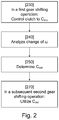
- FIG. 2 shows a flow chart for a method for controlling a backlash of a powertrain included in a vehicle 100 in connection with a gear shifting operation, according to an embodiment of the present invention.
- a clutch 106 included in the powertrain 130 is controlled in connection with a first gear shifting operation.
- a first step 210 and/or a second step 220 may precede the third step 230 according to some embodiments.
- the clutch 106 is in the third step 230 controlled to a slipping position C slip , in which slipping position C slip the clutch 106 transfers a slipping torque T slip being less than a torque T closed being transferred in a closed position C closed for the clutch 106 .
- the clutch 106 i.e. a clutch actuator controlling the position of the clutch, is in a position between a closed position C closed and an open position C open , whereby the slipping torque T slip is lower than a closed torque T closed and higher than an open torque T open being transferred by the clutch 106 in the closed position C closed and in the open position C open , respectively; T open ⁇ T slip ⁇ T closed .
- a change ⁇ dot over ( ⁇ ) ⁇ of a rotational speed ⁇ for an input shaft 109 of the gearbox 103 included in the powertrain 130 is analysed. This analysis will be described more in detail below.
- a position C det for the clutch 106 is determined, such that the change ⁇ dot over ( ⁇ ) ⁇ of the rotational speed has a value ⁇ dot over ( ⁇ ) ⁇ det corresponding to a backlash torque T backlash for that position C det .
- the backlash torque T backlash has here a predetermined value being suitable for eliminating the backlash in the powertrain, as will be described below.
- a seventh step 270 the determined clutch position C det is utilised for controlling the clutch 106 in connection with a second subsequent gear shifting operation.
- a sixth step 260 may precede the seventh step in some embodiments.
- the position C det for the clutch 106 which in connection with a first gear shifting operation has been determined to be suitable for eliminating the powertrain backlash/play, is utilised 270 in a second subsequent gear shifting operation for eliminating the powertrain backlash/play.
- the powertrain oscillations and/or the component wear may be reduced considerably in connection with the second subsequent gear shifting operation. The reduction in powertrain oscillations increases the driver comfort in the vehicle.
- play/backlash in the powertrain may, for example, arise when two cogs in the powertrain, such as for example the cogs in two cogwheels in the gearbox, fail to engage/mesh with each other.
- the position of the cogwheels in relation to each other during and outside of the play is schematically illustrated in the FIGS. 3 a - c .
- the cogs of the cogwheels make contact in a first shaft position, during rotation in a first direction, as illustrated in FIG. 3 a , in a position corresponding to a maximum backward turn.
- the cogs in the cogwheels also make contact in a third shaft position, during rotation in a second direction, as illustrated in FIG. 3 c , in a position corresponding to a maximum forward turn. Therefore, the cogs are engaged/meshed in both these positions (illustrated in FIGS. 3 a and 3 c respectively), which also means that the play is rotated backwards and forwards respectively.
- FIGS. 3 a - c illustrate, in a schematic and simplified manner, a play between only two cogwheels, and that a powertrain may comprise connections between more than two cogwheels, as described above.
- FIGS. 3 a - c may be used to explain, in principle, the occurrence of a play.
- a backlash/play may thus, for example, occur at a transition between dragging the engine and an acceleration/torque request when engaging the clutch, or during a shift operation. Since an efficient elimination/winding up of such a play may be provided by the use of the present invention, a rapid torque build-up may be obtained.
- FIG. 4 shows a flow chart illustrating different embodiments of the present invention including a number of steps being performed in connection with a gear shifting operation, that will hereafter be described.
- FIGS. 5 a - d schematically illustrates a non-limiting example of a first and a second gear shifting operations, that are here used for explaining the principles of the embodiments descried in this document.
- the third 230 , the fourth 240 , the fifth 250 and the seventh 270 steps correspond to the steps described above in connection with FIG. 2 . These steps are only briefly described here, and reference is made to FIG. 2 . In addition to these previously described steps, a number of further steps are described in connection with FIG. 4 and exemplified by the non-limiting first gear shifting operation illustrated in FIGS. 5 a - d.
- the clutch 106 is in a first gear shifting operation controlled 531 to be opened 532 , i.e. is controlled to an open position C open , after which the gearbox 103 is shifted 521 into a neutral gear G neutral .
- the target value ⁇ e_target 540 for a rotational speed ⁇ e of the engine 101 (solid line in FIG. 5 b ) is reduced from a higher value 501 to a lower value 502 .
- the target value ⁇ e_target 540 for the rotational speed ⁇ e of the engine 101 can be calculated based on the rotational speed of the wheels ⁇ drive_wheel and the total target gear ratio g powertrain_target for the powertrain/driveline from the input shaft 109 to the drive wheels 110 , 111 .
- the rotational speed ⁇ 550 for the input shaft 109 of the gearbox 103 ( 550 ; dashed line in FIG. 5 b ) is also reduced.
- the dashed line for the rotational speed ⁇ 550 for the input shaft 109 in FIG. 5 b represents the rotational speed ⁇ in connection with the first gear shifting operation.
- an input shaft brake arrangement providing a braking torque directly or indirectly on the input shaft 109 is activated 511 in order to brake the rotational speed to a value ⁇ low being lower than the target value ⁇ e_target 540 .
- the input shaft brake arrangement can be arranged in a number of ways, as long as a braking torque is applied to the input shaft 109 .
- the braking torque can according to different embodiments be applied directly to the input shaft 109 and/or to another shaft 702 being connected to the input shaft via at least one gear wheel meshing.
- FIG. 7 schematically illustrates one example of a gearbox 103 including an input shaft 109 , and a main/transmission shaft 705 being journaled to the input shaft 109 in bearings 706 .
- a lay shaft brake 701 configured to apply a braking torque to a lay shaft 702 , is schematically illustrated.
- the lay shaft 702 is here braked by the lay shaft brake 701 , and the braking force is then provided to the input shaft 109 of the gearbox 103 via one or more gear wheel meshes 703 , 704 .
- the input shaft brake arrangement may be constructed in a number of ways, and is not limited to the schematic illustration of FIG. 7 . As described in this document, the input shaft brake arrangement may be controlled by a brake control unit 125 included in a control unit 120 .
- the control unit 120 may also include a gearbox control unit 124 .
- first step 210 the gearbox 103 is shifted into a neutral gear position.
- second step 220 the input shaft 109 of the gearbox 103 is braked to a rotational speed 550 having a value ⁇ low being lower than the target value ⁇ e_target for the rotational speed of the engine 101 .
- the rotational speed value ⁇ 550 of the input shaft 109 for the first gear shifting operation (dashed line) is braked passed the target value ⁇ e_target 504 until the input shaft braking arrangement is deactivated 512 when the rotational speed value ⁇ 550 is lower than the target value ⁇ e_target 505 .
- the clutch 106 is then controlled 533 in a third step 230 to the slipping position C slip from the open position C open .
- the positions for the clutch 106 such as the open position C open , the closed position C closed , the slipping position C slip and the determined position C det , each corresponds to a position C act of a clutch actuator controlling a degree of opening for said clutch 106 .
- the position of the clutch/actuator determines the torque being transferred by the clutch 106 .
- the deactivation of the input shaft braking arrangement in combination with the use of the slipping position C slip of the clutch 106 causes the rotational speed ⁇ 550 for the input shaft 109 to increase again after its lowest value 506 .
- the rotational speed ⁇ 550 for the input shaft 109 increases such that a change ⁇ dot over ( ⁇ ) ⁇ of the rotational speed ⁇ 550 is provided.
- This change ⁇ dot over ( ⁇ ) ⁇ of the rotational speed is then in a fourth step 240 analysed during an analysis time period T analysis . This analysis will be described more in detail below.
- the analysis of the change ⁇ dot over ( ⁇ ) ⁇ of the rotational speed can then in a fifth step 250 , be used for determining a position C det for the clutch 106 for which the acceleration/change/derivative ⁇ dot over ( ⁇ ) ⁇ of the rotational speed has a value ⁇ dot over ( ⁇ ) ⁇ det corresponding to a backlash torque T backlash for that position C det .
- the position C det can here be determined such that the backlash torque T backlash corresponding to the value ⁇ dot over ( ⁇ ) ⁇ det has a predetermined value being suitable for eliminating the backlash in the powertrain.
- the different parts of the powertrain have different rotational inertias, comprising a rotational inertia J e for the engine 101 , a rotational inertia J g for the gearbox 103 , a rotational inertia J c for the clutch 106 , a rotational inertia J p for the propeller shaft 107 and rotational inertias J d for each drive shaft 104 , 105 .
- all rotating bodies have a rotational inertia J, which depends on the mass of the body and the distance of the mass from the rotational centre. For reasons of clarity, in FIG.
- the rotational inertia J is known or can be calculated.
- the determined value ⁇ dot over ( ⁇ ) ⁇ det for the change in rotational speed is dependent at least on a rotational inertia J of one or more parts of the clutch 106 and the gearbox 103 .
- a rotational inertia J of one or more parts of the clutch 106 and the gearbox 103 can be e.g. 0.5 kg*m 2 .
- the predetermined value of the backlash torque T backlash suitable for eliminating the backlash/play may be empirically determined and may have a value exceeding at least the frictional torques of the gearbox and the drive shafts 104 , 105 , for example within a range of 10-50 Nm, or within a range of 15-25 Nm, or approximately 20 Nm.
- the value ⁇ dot over ( ⁇ ) ⁇ det for the acceleration/change/derivative ⁇ dot over ( ⁇ ) ⁇ of the rotational speed corresponding to the backlash torque T backlash value being useable for eliminating the backlash/play is calculated.
- the clutch 103 is controlled to be gradually more and more closed from its open position C open 533 (solid line for the first shifting operation in FIG. 5 d ).
- the clutch is gradually closed until the wanted value ⁇ dot over ( ⁇ ) ⁇ et for the acceleration/change/derivative ⁇ dot over ( ⁇ ) ⁇ results 534 from the control of the clutch.
- the backlash torque T backlash is provided to the powertrain, which eliminates/winds up the backlash/play.
- the position C det for the clutch 103 which results in the wanted value ⁇ dot over ( ⁇ ) ⁇ det , and thus also in the backlash torque T backlash is determined based on the actual position of the clutch 103 when the wanted value ⁇ dot over ( ⁇ ) ⁇ det is provided.
- the rotational speed ⁇ 550 of the input shaft 109 then continues to increase, such that it reaches 507 the target value ⁇ e_target 540 for the rotational speed of the engine 101 again.
- the gearbox 103 is changed into a target gear position G target 522 (solid line for the first gear shifting operation in FIG. 5 c ) when the rotational speed ⁇ for the input shaft 109 is essentially equal 507 , e.g. within an interval of ⁇ 40 rpm, with the target value ⁇ e_target for the rotational speed of the engine 101 .
- a sixth step 260 of the method the elimination of the backlash is verified based on an analysis of a difference ⁇ between the rotational speed ⁇ 550 for the input shaft 109 and a converted rotational wheel speed ⁇ wheel .
- the converted rotational wheel speed ⁇ wheel can here be calculated based on a rotational speed of at least one driving wheel 110 , 111 in the vehicle 100 and on a total gearing ratio between the input shaft 109 of the gearbox 103 and the at least one driving wheel 110 , 111 , e.g. including at least the gearing ratio of the gearbox and the differential 108 .
- the backlash torque T backlash is controlled such that the difference ⁇ is less than a predetermined value ⁇ predet ; ⁇ predet ; during the elimination of the backlash.
- a constant and/or predetermined value for the backlash torque T backlash can be requested/provided during the backlash elimination process, which results in a value for the difference ⁇ .
- the difference ⁇ is then analysed in order to determine if the backlash/play has been eliminated or not.
- the value for the backlash torque T backlash is adapted in order to achieve the predetermined value ⁇ predet for the difference ⁇ .
- a controlled elimination of the backlash/play is achieved.
- the first to sixth steps 210 , 220 , 230 , 240 , 250 , 260 are performed in connection with the first gear shifting operation.
- the position C det for the clutch 103 being suitable for eliminating the backlash in the powertrain can be determined in connection with the first gear shifting operation.
- a seventh step 270 the determined clutch position C det is utilised for controlling the clutch 106 in connection with a second subsequent gear shifting operation.
- the clutch position C det having been determined in connection with the first gear shifting operation can then be used later in connection with a second gear shifting operation, as is illustrated with the dot-dashed line 534 in FIG. 5 d.
- the dot-dashed line 551 for the rotational speed ⁇ for the input shaft 109 in FIG. 5 b illustrates the rotational speed ⁇ 551 for the second subsequent gear shifting operation.
- the dot-dashed line 523 for the gears in FIG. 5 c illustrates the gearing in connection with the subsequent second gear shifting operation.
- the target gear G target can be engaged already 504 when the rotational speed ⁇ for the input shaft 551 has a value being essentially equal to the target value ⁇ e_target 502 / 540 for the rotational speed of the engine 101 .
- the rotational speed ⁇ 551 for the second subsequent gear shifting operation can be directly increased 504 when the rotational speed ⁇ for the input shaft has a value being essentially equal to the target value ⁇ e_target 502 / 540 , e.g. within an interval of ⁇ 40 rpm around the target value ⁇ e_target 502 / 540 .
- the first gear shifting operation will according to the present invention, take a little more time than a standard gear shifting operation, but after that, quick and comfortable gear shifting operations are provided according to the present invention.
- the first gear shifting operation can for example be performed in a driving situation in which there is plenty of time to perform the gear shifting operation, and to determine the clutch position C det to be used in one or more upcoming gear shifting operations after the first gear shifting operation.
- the clutch 106 is, according to an embodiment, controlled 270 a to be in the determined clutch position C det when the gearbox 103 is changed into the target gear position G target in connection with the second subsequent gear shifting operation, as is illustrated by the dot-dashed line 534 in FIG. 5 d .
- the determined clutch position C det is here used when the gear wheels and/or shafts in the gearbox 103 corresponding to the target gear position G target engage with each other.
- the clutch 106 is controlled 270 b to be in the determined clutch position C det after the gearbox 103 has been changed into a target gear position G target in connection with the second subsequent gear shifting operation, e.g. at least initially during up-ramping of a powertrain torque T powertrain after the second gear changing operation.
- the clutch 106 is controlled 270 a to be in the determined clutch position C det when the gearbox 103 is changed into the target gear position G target , and is also kept in this position thereafter, e.g. during the up-ramping.
- the closed clutch position C closed may be defined as the clutch being closed and no longer slipping, which also means that the rotational speeds for the clutch's input 102 and output 109 shafts are substantially equal. This may also be expressed as the clutch at this clutch position C closed is able to transfer a higher torque than an actual/momentary torque that is transferred to the input shaft 109 and/or to the driving wheels at a time instant.
- the clutch can according to an embodiment transmit a slip torque, which has a permitted and suitable value to wind up the play of the powertrain and/or to prepare the powertrain for the future torque increase/ramp. This may also be expressed as the powertrain is wound up when the clutch 106 is in the slipping clutch position C slip .
- Control/Activation of the clutch is usually carried out with the use of one or more actuators.
- actuators may for example be hydraulic, pneumatic and/or electrically driven/activated/controlled.
- a system for controlling a backlash of a powertrain 130 included in a vehicle 100 in connection with a gear shifting operation is presented.
- the system includes a clutch control unit 121 , arranged for controlling 230 , in connection with a first gear shifting operation, a clutch 106 included in the powertrain 130 to a slipping position C slip , in which slipping position C slip the clutch 106 transfers a slipping torque T slip being less than a torque T closed being transferred in a closed position C closed for the clutch.
- the system also includes an analysis unit 122 , arranged for analyzing 240 a change of a rotational speed ⁇ for an input shaft 109 of a gearbox 103 included in the powertrain 130 .
- the system also includes a determination unit 123 , arranged for determining 250 a position C det for the clutch 106 , for which position C det the change ⁇ dot over ( ⁇ ) ⁇ of the rotational speed has a value ⁇ dot over ( ⁇ ) ⁇ det corresponding to a backlash torque T backlash , the backlash torque T backlash having a predetermined value suitable for eliminating the backlash.
- the clutch control unit 121 is further arranged for utilizing 270 the determined clutch position C det for controlling the clutch 106 in connection with a second subsequent gear shifting operation.
- the system according to the present invention can be arranged for performing all of the above, in the claims, and in the herein described embodiments method steps.
- the system is hereby provided with the above described advantages for each respective embodiment.
- the present invention is also related to a vehicle 100 , such as a truck, a bus or a car, including the herein described system for controlling a backlash of a powertrain.
- a method for controlling a backlash of a powertrain can also be implemented in a computer program, which, when it is executed in a computer, instructs the computer to execute the method.
- the computer program is usually constituted by a computer program product 603 stored on a non-transitory/non-volatile digital storage medium, in which the computer program is incorporated in the computer-readable medium of the computer program product.
- Said computer-readable medium comprises a suitable memory, such as, for example: ROM (Read-Only Memory), PROM (Programmable Read-Only Memory), EPROM (Erasable PROM), Flash memory, EEPROM (Electrically Erasable PROM), a hard disk unit, etc.
- FIG. 6 shows in schematic representation a control unit 600 .
- the control unit 600 comprises a computing unit 601 , which can be constituted by essentially any suitable type of processor or microcomputer, for example a circuit for digital signal processing (Digital Signal Processor, DSP), or a circuit having a predetermined specific function (Application Specific Integrated Circuit, ASIC).
- the computing unit 601 is connected to a memory unit 602 arranged in the control unit 600 , which memory unit provides the computing unit 601 with, for example, the stored program code and/or the stored data which the computing unit 601 requires to be able to perform computations.
- the computing unit 601 is also arranged to store partial or final results of computations in the memory unit 602 .
- control unit 600 is provided with devices 611 , 612 , 613 , 614 for receiving and transmitting input and output signals.
- These input and output signals can contain waveforms, impulses, or other attributes which, by the devices 611 , 613 for the reception of input signals, can be detected as information and can be converted into signals which can be processed by the computing unit 601 . These signals are then made available to the computing unit 601 .
- the devices 612 , 614 for the transmission of output signals are arranged to convert signals received from the computing unit 601 in order to create output signals by, for example, modulating the signals, which can be transmitted to other parts of and/or systems in the vehicle.
- Each of the connections to the devices for receiving and transmitting input and output signals can be constituted by one or more of a cable; a data bus, such as a CAN bus (Controller Area Network bus), a MOST bus (Media Orientated Systems Transport bus), or some other bus configuration; or by a wireless connection.
- a data bus such as a CAN bus (Controller Area Network bus), a MOST bus (Media Orientated Systems Transport bus), or some other bus configuration
- a wireless connection such as a Wi-Fi connection
- CAN bus Controller Area Network bus
- MOST bus Media Orientated Systems Transport bus
- Control systems in modern vehicles commonly comprise communication bus systems consisting of one or more communication buses for linking a number of electronic control units (ECU's), or controllers, and various components located on the vehicle.
- ECU's electronice control units
- Such a control system can comprise a large number of control units and the responsibility for a specific function can be divided amongst more than one control unit.
- Vehicles of the shown type thus often comprise significantly more control units than are shown in FIGS. 1, 6 and 7 , which is well known to the person skilled in the art within this technical field.
- the present invention is implemented in the control unit 120 .
- the invention can also, however, be implemented wholly or partially in one or more other control units already present in the vehicle, or in some control unit dedicated to the present invention.
- units are often described as being arranged for performing steps of the method according to the invention. This also includes that the units are designed to and/or configured to perform these method steps.
- the at least one control unit 120 is in FIG. 1 illustrated as including separately illustrated units 121 , 122 , 123 , 124 , 125 .
- These units 121 , 122 , 123 , 124 , 125 can, however, be logically separated by physically implemented in the same unit, or can be both logically and physically arranged together.
- These units 121 , 122 , 123 , 124 , 125 can for example correspond to groups of instructions, which can be in the form of programming code, that are input into, and are utilized by a processor/computing unit 601 when the units are active and/or are utilized for performing its method step, respectively.
Landscapes
- Engineering & Computer Science (AREA)
- Mechanical Engineering (AREA)
- Transportation (AREA)
- Automation & Control Theory (AREA)
- General Engineering & Computer Science (AREA)
- Combustion & Propulsion (AREA)
- Chemical & Material Sciences (AREA)
- Physics & Mathematics (AREA)
- Fluid Mechanics (AREA)
- Mathematical Physics (AREA)
- Control Of Transmission Device (AREA)
- Hydraulic Clutches, Magnetic Clutches, Fluid Clutches, And Fluid Joints (AREA)
- Structure Of Transmissions (AREA)
Abstract
Description
analyzing a change {dot over (ω)} of a rotational speed ω for an input shaft of a gearbox included in the powertrain;
determining a position Cdet for the clutch, for which position Cdet the change {dot over (ω)} of the rotational speed has a value {dot over (ω)}det corresponding to a backlash torque Tbacklash, the backlash torque Tbacklash having a predetermined value for eliminating the backlash; and
utilizing the determined clutch position Cdet for controlling the clutch in connection with a second subsequent gear shifting operation.
-
- shifting the gearbox into a neutral gear position; and
- braking the input shaft to a rotational speed value ωlow being lower than a target value ωe_target for a rotational speed of an engine included in the powertrain.
-
- a clutch control unit, arranged for controlling, in connection with a first gear shifting operation, a clutch included in the powertrain to a slipping position Cslip, in which slipping position Cslip the clutch transfers a slipping torque Tslip being less than a torque Tclosed being transferred in a closed position Cclosed for the clutch;
- an analysis unit, arranged for analyzing a change {dot over (ω)} of a rotational speed ω for an input shaft of a gearbox included in the powertrain;
- a determination unit, arranged for determining a position Cdet for the clutch, for which position Cdet the change {dot over (ω)} of the rotational speed has a value {dot over (ω)}det corresponding to a backlash torque Tbacklash, the backlash torque Tbacklash having a predetermined value suitable for eliminating the backlash; and
- the clutch control unit, arranged for utilizing the determined clutch position Cdet for controlling the clutch in connection with a second subsequent gear shifting operation.
Claims (14)
Applications Claiming Priority (4)
| Application Number | Priority Date | Filing Date | Title |
|---|---|---|---|
| SE1650490 | 2016-04-12 | ||
| SE1650490A SE539831C2 (en) | 2016-04-12 | 2016-04-12 | Control of a powertrain backlash |
| SE1650490-4 | 2016-04-12 | ||
| PCT/SE2017/050331 WO2017180043A1 (en) | 2016-04-12 | 2017-04-03 | Control of a powertrain backlash |
Publications (2)
| Publication Number | Publication Date |
|---|---|
| US20190128345A1 US20190128345A1 (en) | 2019-05-02 |
| US10634200B2 true US10634200B2 (en) | 2020-04-28 |
Family
ID=60042627
Family Applications (1)
| Application Number | Title | Priority Date | Filing Date |
|---|---|---|---|
| US16/091,367 Active US10634200B2 (en) | 2016-04-12 | 2017-04-03 | Control of a powertrain backlash |
Country Status (6)
| Country | Link |
|---|---|
| US (1) | US10634200B2 (en) |
| EP (1) | EP3442842B1 (en) |
| KR (1) | KR102093957B1 (en) |
| CN (1) | CN108883769B (en) |
| SE (1) | SE539831C2 (en) |
| WO (1) | WO2017180043A1 (en) |
Families Citing this family (6)
| Publication number | Priority date | Publication date | Assignee | Title |
|---|---|---|---|---|
| WO2020091435A1 (en) | 2018-10-31 | 2020-05-07 | 주식회사 엘지화학 | Electrolyte having differential ionic conductivity and lithium secondary battery comprising same |
| KR102703274B1 (en) * | 2019-06-13 | 2024-09-04 | 현대자동차주식회사 | System and method for reducing acceleration shock of a motor driven vehicle |
| JP2021067271A (en) * | 2019-10-17 | 2021-04-30 | ヤマハ発動機株式会社 | Automatic transmission for vehicle, and vehicle including the same |
| CN115111289B (en) * | 2022-06-30 | 2024-05-03 | 广汽埃安新能源汽车有限公司 | Tooth clutch control method and device, electronic equipment and storage medium |
| CN117006244B (en) * | 2023-08-07 | 2025-09-12 | 北理华创(佛山)新能源汽车科技有限公司 | Coordinated shifting method and system |
| SE2351136A1 (en) * | 2023-10-03 | 2025-04-04 | Scania Cv Ab | Method for reducing backlash in a vehicle and control arrangent configured to perform the method |
Citations (18)
| Publication number | Priority date | Publication date | Assignee | Title |
|---|---|---|---|---|
| WO2002087916A1 (en) | 2001-04-27 | 2002-11-07 | Volvo Lastvagnar Ab | Drive means for motor vehicles |
| US20030054920A1 (en) | 2000-02-15 | 2003-03-20 | Luk Lamellen Und Kupplungsbau Beteiligungs Kg | Method of controlling a transmission |
| US20060016656A1 (en) | 2003-01-27 | 2006-01-26 | Klaus Kuepper | Drive train and method for controlling a drive train |
| GB2448671A (en) | 2007-01-20 | 2008-10-29 | Ford Global Technologies Llc | A method of controlling driveline backlash |
| WO2011003544A2 (en) | 2009-07-07 | 2011-01-13 | Volvo Lastvagnar Ab | Method and controller for controlling output torque of a propulsion unit. |
| US20120115679A1 (en) | 2010-07-09 | 2012-05-10 | Ford Global Technologies, Llc | Method for controlling a transmission coupled to an engine that may be automatically stopped |
| US20120160046A1 (en) | 2009-06-25 | 2012-06-28 | Schaeffler Technologies Gmbh & Co. Kg | Drive train having clutch activation for overcoming the backlash of the drive train before start-up |
| US8239113B2 (en) * | 2006-03-07 | 2012-08-07 | Ford Global Technologies, Llc | Vehicle response during vehicle acceleration conditions |
| US8332111B2 (en) * | 2010-11-01 | 2012-12-11 | Ford Global Technologies, Llc | Dual clutch driveline twist control |
| US20130096789A1 (en) | 2010-11-01 | 2013-04-18 | Ford Global Technologies, Llc | Bounded Vehicle Driveline Twist Estimating |
| US20130296106A1 (en) | 2012-05-07 | 2013-11-07 | Ford Global Technologies, Llc | Method and system for controlling driveline lash in a hybrid vehicle |
| DE102013220626A1 (en) | 2013-10-14 | 2015-04-16 | Zf Friedrichshafen Ag | Method and control unit for controlling a starting clutch |
| EP2949907A1 (en) | 2014-05-30 | 2015-12-02 | Scania CV AB | Adjustment of a torque requested form an engine |
| WO2015183160A1 (en) | 2014-05-30 | 2015-12-03 | Scania Cv Ab | Torque control of a vehicle powertrain based on a time derivative for a dynamic torque |
| EP2987695A1 (en) | 2014-08-18 | 2016-02-24 | Scania CV AB | Control of a torque from an engine |
| US9637108B2 (en) * | 2012-12-12 | 2017-05-02 | Nissan Motor Co., Ltd. | Vehicle driving-torque control device |
| US9869355B2 (en) * | 2012-11-19 | 2018-01-16 | Allison Transmission, Inc. | Adjustable control of power take-off subsystem damping and system thereof |
| US20180178803A1 (en) * | 2016-12-22 | 2018-06-28 | Eaton Corporation | System, method, and apparatus for operating a high efficiency, high output transmission |
-
2016
- 2016-04-12 SE SE1650490A patent/SE539831C2/en unknown
-
2017
- 2017-04-03 EP EP17782741.7A patent/EP3442842B1/en active Active
- 2017-04-03 KR KR1020187031650A patent/KR102093957B1/en active Active
- 2017-04-03 CN CN201780020060.1A patent/CN108883769B/en active Active
- 2017-04-03 WO PCT/SE2017/050331 patent/WO2017180043A1/en not_active Ceased
- 2017-04-03 US US16/091,367 patent/US10634200B2/en active Active
Patent Citations (20)
| Publication number | Priority date | Publication date | Assignee | Title |
|---|---|---|---|---|
| US20030054920A1 (en) | 2000-02-15 | 2003-03-20 | Luk Lamellen Und Kupplungsbau Beteiligungs Kg | Method of controlling a transmission |
| WO2002087916A1 (en) | 2001-04-27 | 2002-11-07 | Volvo Lastvagnar Ab | Drive means for motor vehicles |
| US20060016656A1 (en) | 2003-01-27 | 2006-01-26 | Klaus Kuepper | Drive train and method for controlling a drive train |
| US8239113B2 (en) * | 2006-03-07 | 2012-08-07 | Ford Global Technologies, Llc | Vehicle response during vehicle acceleration conditions |
| GB2448671A (en) | 2007-01-20 | 2008-10-29 | Ford Global Technologies Llc | A method of controlling driveline backlash |
| US20120160046A1 (en) | 2009-06-25 | 2012-06-28 | Schaeffler Technologies Gmbh & Co. Kg | Drive train having clutch activation for overcoming the backlash of the drive train before start-up |
| US8584545B2 (en) * | 2009-06-25 | 2013-11-19 | Schaeffler Technologies AG & Co. KG | Drive train having clutch activation for overcoming the backlash of the drive train before start-up |
| WO2011003544A2 (en) | 2009-07-07 | 2011-01-13 | Volvo Lastvagnar Ab | Method and controller for controlling output torque of a propulsion unit. |
| US20120115679A1 (en) | 2010-07-09 | 2012-05-10 | Ford Global Technologies, Llc | Method for controlling a transmission coupled to an engine that may be automatically stopped |
| US8793057B2 (en) * | 2010-11-01 | 2014-07-29 | Ford Global Technologies, Llc | Bounded vehicle driveline twist estimating |
| US8332111B2 (en) * | 2010-11-01 | 2012-12-11 | Ford Global Technologies, Llc | Dual clutch driveline twist control |
| US20130096789A1 (en) | 2010-11-01 | 2013-04-18 | Ford Global Technologies, Llc | Bounded Vehicle Driveline Twist Estimating |
| US20130296106A1 (en) | 2012-05-07 | 2013-11-07 | Ford Global Technologies, Llc | Method and system for controlling driveline lash in a hybrid vehicle |
| US9869355B2 (en) * | 2012-11-19 | 2018-01-16 | Allison Transmission, Inc. | Adjustable control of power take-off subsystem damping and system thereof |
| US9637108B2 (en) * | 2012-12-12 | 2017-05-02 | Nissan Motor Co., Ltd. | Vehicle driving-torque control device |
| DE102013220626A1 (en) | 2013-10-14 | 2015-04-16 | Zf Friedrichshafen Ag | Method and control unit for controlling a starting clutch |
| EP2949907A1 (en) | 2014-05-30 | 2015-12-02 | Scania CV AB | Adjustment of a torque requested form an engine |
| WO2015183160A1 (en) | 2014-05-30 | 2015-12-03 | Scania Cv Ab | Torque control of a vehicle powertrain based on a time derivative for a dynamic torque |
| EP2987695A1 (en) | 2014-08-18 | 2016-02-24 | Scania CV AB | Control of a torque from an engine |
| US20180178803A1 (en) * | 2016-12-22 | 2018-06-28 | Eaton Corporation | System, method, and apparatus for operating a high efficiency, high output transmission |
Non-Patent Citations (4)
| Title |
|---|
| International Search Report for International Patent Application No. PCT/SE2017/050331 dated May 30, 2017. |
| Scania CV AB, European Application No. 17782741.7, Extended European Search Report, dated Oct. 18, 2019. |
| Swedish Office Action for SE International Patent Application No. 1650490-4 dated Oct. 24, 2016. |
| Written Opinion of the International Searching Authority for International Patent Application No. PCT/SE2017/050331 dated May 30, 2017. |
Also Published As
| Publication number | Publication date |
|---|---|
| CN108883769B (en) | 2021-10-15 |
| BR112018068825A2 (en) | 2019-01-22 |
| SE539831C2 (en) | 2017-12-12 |
| CN108883769A (en) | 2018-11-23 |
| EP3442842B1 (en) | 2025-03-12 |
| EP3442842A4 (en) | 2019-11-20 |
| KR102093957B1 (en) | 2020-04-23 |
| US20190128345A1 (en) | 2019-05-02 |
| EP3442842A1 (en) | 2019-02-20 |
| WO2017180043A1 (en) | 2017-10-19 |
| KR20180131593A (en) | 2018-12-10 |
| SE1650490A1 (en) | 2017-10-13 |
Similar Documents
| Publication | Publication Date | Title |
|---|---|---|
| US10634200B2 (en) | Control of a powertrain backlash | |
| US11780443B2 (en) | Method and system for controlling at least one electrical machine | |
| US10899351B2 (en) | Hybrid powertrain system and operation with transfer case in low gear | |
| EP3467353A1 (en) | A method for controlling a transmission | |
| US20180058575A1 (en) | Shift-by-wire control of vehicle transmission | |
| CN110121606A (en) | power transmission control device | |
| JP2021055842A (en) | Method for controlling road vehicle for execution of standing start | |
| EP2987695B1 (en) | Control of a torque from an engine | |
| SE537011C2 (en) | Regulation of a requested torque in a vehicle | |
| SE542021C2 (en) | Method for shutting down a combustion engine of a vehicle powertrain, control device, vehicle, computer program and computer readable medium | |
| EP1746004A8 (en) | System and method controlling the coupling between the driveshaft and the primary gear shaft in a motor vehicle with a servo-controlled gearbox | |
| US10821985B2 (en) | Gear change control device and gear change control method | |
| SE539830C2 (en) | Method and system for setting a vehicle in motion | |
| EP3763586B1 (en) | Method of controlling a pickup manoeuvre of a hybrid vehicle | |
| US20160010726A1 (en) | Transmission for a vehicle | |
| US20250243931A1 (en) | Drive axle system and method of control | |
| BR112018068825B1 (en) | METHOD FOR CONTROLING POWERTRAIN CLEARANCE, COMPUTER READABLE MEANS AND SYSTEM ARRANGEMENT FOR CONTROLING POWERTRAIN CLEARANCE | |
| US10781764B2 (en) | Target torque control device and target torque control method | |
| SE538734C2 (en) | Control of a torque requested by an engine | |
| JP2021054400A (en) | Method to control road vehicle with microslip of clutch | |
| SE541781C2 (en) | Method and system for controlling torque transmitting means of a vehicle | |
| DE102015007012A1 (en) | Control of at least one actuator |
Legal Events
| Date | Code | Title | Description |
|---|---|---|---|
| AS | Assignment |
Owner name: SCANIA CV AB, SWEDEN Free format text: ASSIGNMENT OF ASSIGNORS INTEREST;ASSIGNORS:UDD, JONAS;KJELL, ANDERS;SIGNING DATES FROM 20180912 TO 20180913;REEL/FRAME:047071/0369 |
|
| FEPP | Fee payment procedure |
Free format text: ENTITY STATUS SET TO UNDISCOUNTED (ORIGINAL EVENT CODE: BIG.); ENTITY STATUS OF PATENT OWNER: LARGE ENTITY |
|
| STPP | Information on status: patent application and granting procedure in general |
Free format text: DOCKETED NEW CASE - READY FOR EXAMINATION |
|
| STPP | Information on status: patent application and granting procedure in general |
Free format text: NOTICE OF ALLOWANCE MAILED -- APPLICATION RECEIVED IN OFFICE OF PUBLICATIONS |
|
| STPP | Information on status: patent application and granting procedure in general |
Free format text: AWAITING TC RESP., ISSUE FEE NOT PAID |
|
| STPP | Information on status: patent application and granting procedure in general |
Free format text: NOTICE OF ALLOWANCE MAILED -- APPLICATION RECEIVED IN OFFICE OF PUBLICATIONS |
|
| STCF | Information on status: patent grant |
Free format text: PATENTED CASE |
|
| MAFP | Maintenance fee payment |
Free format text: PAYMENT OF MAINTENANCE FEE, 4TH YEAR, LARGE ENTITY (ORIGINAL EVENT CODE: M1551); ENTITY STATUS OF PATENT OWNER: LARGE ENTITY Year of fee payment: 4 |