US106295A - Improvement in machines for bending- tttbe-skelfs - Google Patents
Improvement in machines for bending- tttbe-skelfs Download PDFInfo
- Publication number
- US106295A US106295A US106295DA US106295A US 106295 A US106295 A US 106295A US 106295D A US106295D A US 106295DA US 106295 A US106295 A US 106295A
- Authority
- US
- United States
- Prior art keywords
- rolls
- bending
- shaft
- skelp
- machines
- Prior art date
- Legal status (The legal status is an assumption and is not a legal conclusion. Google has not performed a legal analysis and makes no representation as to the accuracy of the status listed.)
- Expired - Lifetime
Links
- 238000005452 bending Methods 0.000 description 7
- 239000002184 metal Substances 0.000 description 1
- 229910052751 metal Inorganic materials 0.000 description 1
- 238000000034 method Methods 0.000 description 1
Images
Classifications
-
- B—PERFORMING OPERATIONS; TRANSPORTING
- B21—MECHANICAL METAL-WORKING WITHOUT ESSENTIALLY REMOVING MATERIAL; PUNCHING METAL
- B21D—WORKING OR PROCESSING OF SHEET METAL OR METAL TUBES, RODS OR PROFILES WITHOUT ESSENTIALLY REMOVING MATERIAL; PUNCHING METAL
- B21D5/00—Bending sheet metal along straight lines, e.g. to form simple curves
- B21D5/06—Bending sheet metal along straight lines, e.g. to form simple curves by drawing procedure making use of dies or forming-rollers, e.g. making profiles
- B21D5/08—Bending sheet metal along straight lines, e.g. to form simple curves by drawing procedure making use of dies or forming-rollers, e.g. making profiles making use of forming-rollers
Definitions
- My invention mainly consists inthe combination of three grooved rolls, for givingthe finished formv to the skelps.
- Two of these rolls run in the saine plan'e, and have grooves in one ledge for forming the requisite portion of a circle, to partly close the skelp, the bending of which had been commenced by anotherdevice.
- a third roll is used, which runs in a plane at right angles to said rolls.
- rlhe invention further consists in the combination of the three rolls above described with two other rolls, one of'which basan annular groove and the other a similar tongue, to partly bend the'skelp before it ente-rs the inst-mentioned rolls, as hereinafter described.
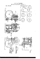
- Figure 1 is a plan view ofthe improved machine.
- v Figure 2 is a side-elevation of the same.
- Figure 3 is a front view.
- Figure 4 is a vertical section at the line a; x of Iig. 3.
- Figure 5 is an end view of a flat skelp, for forming a butt-joint tube.
- Figures 6, 7and ⁇ 8 are end views of the butt-joint skelp, in the diifereut stages of the bending operation.
- Figure 9 is an end view of a flat skelp, for forming a lap-joint tube.
- Figures 10, 11, and 12 are endl views, which the lapjoint skelp assumes in the different stages of the bending process..
- A is the bed-plate of the improved machine
- U is a horizontal shaft, on which is situated the roll D, which has an annular' groove, a, in its periphery.
- O is a shaft, connected with the shaft C by means of gear-wheels E und E' on one end of the shafts.
- G is the driving-shaft connected with. the motive power.
- one end of the shaft is the driving-wheelH
- the shhfts K K are geared together by' means of the wheels L L, and motion is communicated from the driving-wheel H through the spur-wl1eel M, on one end of the short horizontal 'shaft N, and the miterwheels O O-oue on the other end of said shaft N, and the other on the lower end of one of the shafts K.
- the said rolls being constructed, arranged, and operating substantially in the manner and for the purpose set forth.
Landscapes
- Engineering & Computer Science (AREA)
- Mechanical Engineering (AREA)
- Bending Of Plates, Rods, And Pipes (AREA)
Description
S.P.M.TASK"ER. MACHINE FOR BENDINGTUBB SKELPS.
Patented Aug 9, 1870l BUTT JOINT4 LAP JUlNT OQF IGME
` PHY...
STEPHEN P. M. TASKER, OF PHILADELPHIA, PENNSYLVANIA.
Lene/rs Para.: No. 106,295, dated August 9, 1870.
Qow IMPROVEMENT IN MACHINES FOR BENDING- TUBE-SKELFS.
The Schedule referred to in these Letters Patent and making part of the same I, STEPHEN P. M. TASKER, of the city of Philadelphia and State of Pennsylvania, have invented certain Improvementsin Machines for Bending Metal Tube-Skelps, of which the following is a specification.
My invention'mainly consists inthe combination of three grooved rolls, for givingthe finished formv to the skelps.
Two of these rolls run in the saine plan'e, and have grooves in one ledge for forming the requisite portion of a circle, to partly close the skelp, the bending of which had been commenced by anotherdevice.
In conjunction with these two rolls a third roll is used, which runs in a plane at right angles to said rolls.
The groeve in lthis roll completes a circle with the grooves of the other two, so that the combined operation of the three rolls gives a finished bending of the skelp.
rlhe invention further consists in the combination of the three rolls above described with two other rolls, one of'which basan annular groove and the other a similar tongue, to partly bend the'skelp before it ente-rs the inst-mentioned rolls, as hereinafter described.
'Io enable others skilled in the art to which my improvement appertains to make'and use my invention,
I will now give adetailed description thereof.
In the accompanying drawingr which makes a part of this specification-A Figure 1 is a plan view ofthe improved machine.
vFigure 2 is a side-elevation of the same.
Figure 3 is a front view.
Figure 4 is a vertical section at the line a; x of Iig. 3.
Figure 5 is an end view of a flat skelp, for forming a butt-joint tube.
Figures 6, 7and `8 are end views of the butt-joint skelp, in the diifereut stages of the bending operation.
Figure 9 is an end view of a flat skelp, for forming a lap-joint tube.
Figures 10, 11, and 12 are endl views, which the lapjoint skelp assumes in the different stages of the bending process..
Like lettersiu all the figures indicate the same parts.
A is the bed-plate of the improved machine, and
B B, the h ousens.
U is a horizontal shaft, on which is situated the roll D, which has an annular' groove, a, in its periphery.
O is a shaft, connected with the shaft C by means of gear-wheels E und E' on one end of the shafts.
0n the said shaft C there is a roll, D', which is provided with an annular tongue, b, which runs in the groove a of the wheel D.
G is the driving-shaft connected with. the motive power.
0n one end of the shaft is the driving-wheelH,
' which gears into the wheel E on the shaft C, and coinmunicates motion to the said shafts C and C', and thereby to the rolls D and D', above described, wherehy the skelp, as it is carried forward by the revolutions of said rolls in the direction of the arrows, is brought. into the form represented in figs. 6 and 10.
For giving the form to the skelps seen in gs. 7 and 11, I use the horizontal rolls J J on the upper ends of the shafts K K, the said rolls having grooves, d d, in their upper corner, as represented in fig. 3, so as to form the requisite portion of a circle, to' give that form to the skelps.
And fornishing the bend, I use the roll J on the shaft K", the said roll beingyat rightangles to therolls J J and its groove d', completing the circle with the groove d d.
Consequently' the combined action of vthe three rolls, J J audJ, nishes the bending of the skelp, for either butt or lap-joints, as represented in figs. 8 and 12.. i
The shhfts K K are geared together by' means of the wheels L L, and motion is communicated from the driving-wheel H through the spur-wl1eel M, on one end of the short horizontal 'shaft N, and the miterwheels O O-oue on the other end of said shaft N, and the other on the lower end of one of the shafts K.
lMotion is communicated to the shaft K by means ofthe gear-wheels 1J P, one on the said shaft and the other on one end of the shaft C, the other end of the shaft having a geared connection with the driving wheel H, as before described.
I use suitable guides for conducting the skelp between the rolls and mandrels, for maintaining the iutex-nal form of the skelps; but as the arrangement of such guides and mandi-els is well known inthe arts, I have deemed it unnecessary to give a particular description thereof.
What I claim as my invention, and desire to secure by Let-ters Patent, is-
l. The combination of the grooved rolls J J and J on shafts K K and K', driven by suitable mechanism,
the said rolls being constructed, arranged, and operating substantially in the manner and for the purpose set forth.
2. The combination of the said rolls J J and J with the rolls D and D', the two sets of rolls being arranged and operating in relation to each other, for
bending the skelp at one operation, substantially as described.
In testimony that the above is my invention,I have hereunto set my hand and atlixed my seal this 13th day ofJune, 1870.
STEPHEN P. M. TASKER. [L s.]
Witnesses:
THOMAS J. BEWLEY, STEPHEN Usines;
Publications (1)
| Publication Number | Publication Date |
|---|---|
| US106295A true US106295A (en) | 1870-08-09 |
Family
ID=2175771
Family Applications (1)
| Application Number | Title | Priority Date | Filing Date |
|---|---|---|---|
| US106295D Expired - Lifetime US106295A (en) | Improvement in machines for bending- tttbe-skelfs |
Country Status (1)
| Country | Link |
|---|---|
| US (1) | US106295A (en) |
-
0
- US US106295D patent/US106295A/en not_active Expired - Lifetime
Similar Documents
| Publication | Publication Date | Title |
|---|---|---|
| US106295A (en) | Improvement in machines for bending- tttbe-skelfs | |
| US819644A (en) | Sheet-metal-working machine. | |
| US524199A (en) | fairbairn | |
| US1376497A (en) | Rolling or bending machine | |
| US998087A (en) | Machine for straightening and cutting wire. | |
| US42605A (en) | Improvement in construction of cog-wheels | |
| US347005A (en) | Machine for rolling i-beams | |
| US836735A (en) | Can-heading machine. | |
| US111015A (en) | Improvement in machines for slitting, beveling, and bending metal-tube skelps | |
| US128911A (en) | Improvement in machines for making sheet-metal tubes | |
| US56561A (en) | Improvement in machines for making metal tubes | |
| US982888A (en) | Apparatus for rolling metal shapes. | |
| US299293A (en) | Machine for bending nut-locks | |
| US935906A (en) | Sheet-metal-bending machine. | |
| US101872A (en) | Improvement in driving-gearing | |
| US319753A (en) | Machine for making car-wheels | |
| US882133A (en) | Bending-machine. | |
| US417553A (en) | Machine for bending pipe | |
| US146358A (en) | Improvement in machines for manufacturing metal tubing | |
| US200196A (en) | Improvement in machines for forming chain-links | |
| US266976A (en) | daelen | |
| US154083A (en) | Improvement in machines for bending tube-skelps | |
| US72547A (en) | Improvement in machines for bending hooks | |
| US380577A (en) | Apparatus for making drills | |
| US5399A (en) | Kolliltgr and compressing puddlers balls |