US10629343B2 - Rare earth permanent magnet and rare earth permanent magnet manufacturing method - Google Patents
Rare earth permanent magnet and rare earth permanent magnet manufacturing method Download PDFInfo
- Publication number
- US10629343B2 US10629343B2 US15/146,932 US201615146932A US10629343B2 US 10629343 B2 US10629343 B2 US 10629343B2 US 201615146932 A US201615146932 A US 201615146932A US 10629343 B2 US10629343 B2 US 10629343B2
- Authority
- US
- United States
- Prior art keywords
- rare earth
- permanent magnet
- earth permanent
- types
- aluminum
- Prior art date
- Legal status (The legal status is an assumption and is not a legal conclusion. Google has not performed a legal analysis and makes no representation as to the accuracy of the status listed.)
- Active, expires
Links
- 229910052761 rare earth metal Inorganic materials 0.000 title claims abstract description 104
- 150000002910 rare earth metals Chemical class 0.000 title claims abstract description 101
- 238000004519 manufacturing process Methods 0.000 title claims description 19
- XEEYBQQBJWHFJM-UHFFFAOYSA-N Iron Chemical compound [Fe] XEEYBQQBJWHFJM-UHFFFAOYSA-N 0.000 claims abstract description 144
- 229910052782 aluminium Inorganic materials 0.000 claims abstract description 77
- XAGFODPZIPBFFR-UHFFFAOYSA-N aluminium Chemical compound [Al] XAGFODPZIPBFFR-UHFFFAOYSA-N 0.000 claims abstract description 74
- GUTLYIVDDKVIGB-UHFFFAOYSA-N cobalt atom Chemical compound [Co] GUTLYIVDDKVIGB-UHFFFAOYSA-N 0.000 claims abstract description 65
- 229910052796 boron Inorganic materials 0.000 claims abstract description 64
- 229910052779 Neodymium Inorganic materials 0.000 claims abstract description 59
- 229910017052 cobalt Inorganic materials 0.000 claims abstract description 59
- 239000010941 cobalt Substances 0.000 claims abstract description 59
- ZOXJGFHDIHLPTG-UHFFFAOYSA-N Boron Chemical compound [B] ZOXJGFHDIHLPTG-UHFFFAOYSA-N 0.000 claims abstract description 56
- 229910001172 neodymium magnet Inorganic materials 0.000 claims abstract description 55
- WHXSMMKQMYFTQS-UHFFFAOYSA-N Lithium Chemical compound [Li] WHXSMMKQMYFTQS-UHFFFAOYSA-N 0.000 claims abstract description 54
- XUIMIQQOPSSXEZ-UHFFFAOYSA-N Silicon Chemical compound [Si] XUIMIQQOPSSXEZ-UHFFFAOYSA-N 0.000 claims abstract description 54
- 229910052790 beryllium Inorganic materials 0.000 claims abstract description 54
- ATBAMAFKBVZNFJ-UHFFFAOYSA-N beryllium atom Chemical compound [Be] ATBAMAFKBVZNFJ-UHFFFAOYSA-N 0.000 claims abstract description 54
- 229910052744 lithium Inorganic materials 0.000 claims abstract description 54
- 229910052710 silicon Inorganic materials 0.000 claims abstract description 54
- 239000010703 silicon Substances 0.000 claims abstract description 54
- 150000001875 compounds Chemical class 0.000 claims abstract description 50
- QEFYFXOXNSNQGX-UHFFFAOYSA-N neodymium atom Chemical compound [Nd] QEFYFXOXNSNQGX-UHFFFAOYSA-N 0.000 claims abstract description 50
- 229910052742 iron Inorganic materials 0.000 claims abstract description 47
- 239000013078 crystal Substances 0.000 claims description 95
- 239000002245 particle Substances 0.000 claims description 90
- 230000004907 flux Effects 0.000 claims description 54
- 239000002994 raw material Substances 0.000 claims description 52
- 229910052771 Terbium Inorganic materials 0.000 claims description 45
- GZCRRIHWUXGPOV-UHFFFAOYSA-N terbium atom Chemical compound [Tb] GZCRRIHWUXGPOV-UHFFFAOYSA-N 0.000 claims description 42
- 229910052777 Praseodymium Inorganic materials 0.000 claims description 31
- 238000010438 heat treatment Methods 0.000 claims description 30
- PUDIUYLPXJFUGB-UHFFFAOYSA-N praseodymium atom Chemical compound [Pr] PUDIUYLPXJFUGB-UHFFFAOYSA-N 0.000 claims description 30
- 229910052692 Dysprosium Inorganic materials 0.000 claims description 23
- KBQHZAAAGSGFKK-UHFFFAOYSA-N dysprosium atom Chemical compound [Dy] KBQHZAAAGSGFKK-UHFFFAOYSA-N 0.000 claims description 23
- 229910052802 copper Inorganic materials 0.000 claims description 21
- 239000010949 copper Substances 0.000 claims description 21
- RYGMFSIKBFXOCR-UHFFFAOYSA-N Copper Chemical compound [Cu] RYGMFSIKBFXOCR-UHFFFAOYSA-N 0.000 claims description 20
- QCWXUUIWCKQGHC-UHFFFAOYSA-N Zirconium Chemical compound [Zr] QCWXUUIWCKQGHC-UHFFFAOYSA-N 0.000 claims description 15
- 239000000203 mixture Substances 0.000 claims description 15
- 239000010955 niobium Substances 0.000 claims description 15
- 229910052726 zirconium Inorganic materials 0.000 claims description 15
- 229910052733 gallium Inorganic materials 0.000 claims description 14
- 229910052758 niobium Inorganic materials 0.000 claims description 14
- 229910052719 titanium Inorganic materials 0.000 claims description 14
- 239000010936 titanium Substances 0.000 claims description 14
- GYHNNYVSQQEPJS-UHFFFAOYSA-N Gallium Chemical compound [Ga] GYHNNYVSQQEPJS-UHFFFAOYSA-N 0.000 claims description 13
- RTAQQCXQSZGOHL-UHFFFAOYSA-N Titanium Chemical compound [Ti] RTAQQCXQSZGOHL-UHFFFAOYSA-N 0.000 claims description 13
- GUCVJGMIXFAOAE-UHFFFAOYSA-N niobium atom Chemical compound [Nb] GUCVJGMIXFAOAE-UHFFFAOYSA-N 0.000 claims description 13
- 239000012071 phase Substances 0.000 description 83
- 238000004458 analytical method Methods 0.000 description 56
- 229910045601 alloy Inorganic materials 0.000 description 55
- 239000000956 alloy Substances 0.000 description 55
- 239000010410 layer Substances 0.000 description 44
- 239000000470 constituent Substances 0.000 description 37
- 238000010586 diagram Methods 0.000 description 24
- 239000000843 powder Substances 0.000 description 24
- 238000000034 method Methods 0.000 description 21
- 239000000047 product Substances 0.000 description 20
- 238000003991 Rietveld refinement Methods 0.000 description 15
- 230000000052 comparative effect Effects 0.000 description 13
- AWFYPPSBLUWMFQ-UHFFFAOYSA-N 2-[5-[2-(2,3-dihydro-1H-inden-2-ylamino)pyrimidin-5-yl]-1,3,4-oxadiazol-2-yl]-1-(1,4,6,7-tetrahydropyrazolo[4,3-c]pyridin-5-yl)ethanone Chemical compound C1C(CC2=CC=CC=C12)NC1=NC=C(C=N1)C1=NN=C(O1)CC(=O)N1CC2=C(CC1)NN=C2 AWFYPPSBLUWMFQ-UHFFFAOYSA-N 0.000 description 12
- 230000005415 magnetization Effects 0.000 description 11
- 238000005259 measurement Methods 0.000 description 11
- 238000006722 reduction reaction Methods 0.000 description 10
- 238000000465 moulding Methods 0.000 description 9
- 239000002114 nanocomposite Substances 0.000 description 9
- 230000000717 retained effect Effects 0.000 description 9
- 238000012545 processing Methods 0.000 description 8
- 239000000523 sample Substances 0.000 description 7
- 239000000126 substance Substances 0.000 description 7
- 230000002708 enhancing effect Effects 0.000 description 6
- 230000005389 magnetism Effects 0.000 description 6
- 239000002105 nanoparticle Substances 0.000 description 6
- 230000009467 reduction Effects 0.000 description 6
- 230000007423 decrease Effects 0.000 description 5
- 238000009826 distribution Methods 0.000 description 5
- 238000000691 measurement method Methods 0.000 description 5
- 238000012360 testing method Methods 0.000 description 5
- 239000000654 additive Substances 0.000 description 4
- 230000000996 additive effect Effects 0.000 description 4
- 238000000748 compression moulding Methods 0.000 description 4
- 230000000694 effects Effects 0.000 description 4
- 239000007789 gas Substances 0.000 description 4
- 239000002904 solvent Substances 0.000 description 4
- 229910002546 FeCo Inorganic materials 0.000 description 3
- 238000000227 grinding Methods 0.000 description 3
- 230000036961 partial effect Effects 0.000 description 3
- 230000002829 reductive effect Effects 0.000 description 3
- 238000007670 refining Methods 0.000 description 3
- ZNEMGFATAVGQSF-UHFFFAOYSA-N 1-(2-amino-6,7-dihydro-4H-[1,3]thiazolo[4,5-c]pyridin-5-yl)-2-[5-[2-(2,3-dihydro-1H-inden-2-ylamino)pyrimidin-5-yl]-1,3,4-oxadiazol-2-yl]ethanone Chemical compound NC=1SC2=C(CN(CC2)C(CC=2OC(=NN=2)C=2C=NC(=NC=2)NC2CC3=CC=CC=C3C2)=O)N=1 ZNEMGFATAVGQSF-UHFFFAOYSA-N 0.000 description 2
- XXZCIYUJYUESMD-UHFFFAOYSA-N 2-[4-[2-(2,3-dihydro-1H-inden-2-ylamino)pyrimidin-5-yl]-3-(morpholin-4-ylmethyl)pyrazol-1-yl]-1-(2,4,6,7-tetrahydrotriazolo[4,5-c]pyridin-5-yl)ethanone Chemical compound C1C(CC2=CC=CC=C12)NC1=NC=C(C=N1)C=1C(=NN(C=1)CC(=O)N1CC2=C(CC1)NN=N2)CN1CCOCC1 XXZCIYUJYUESMD-UHFFFAOYSA-N 0.000 description 2
- FYELSNVLZVIGTI-UHFFFAOYSA-N 2-[4-[2-(2,3-dihydro-1H-inden-2-ylamino)pyrimidin-5-yl]-5-ethylpyrazol-1-yl]-1-(2,4,6,7-tetrahydrotriazolo[4,5-c]pyridin-5-yl)ethanone Chemical compound C1C(CC2=CC=CC=C12)NC1=NC=C(C=N1)C=1C=NN(C=1CC)CC(=O)N1CC2=C(CC1)NN=N2 FYELSNVLZVIGTI-UHFFFAOYSA-N 0.000 description 2
- 101100409686 Mus musculus Psmb8 gene Proteins 0.000 description 2
- 238000004364 calculation method Methods 0.000 description 2
- 229940125904 compound 1 Drugs 0.000 description 2
- 238000001816 cooling Methods 0.000 description 2
- RKTYLMNFRDHKIL-UHFFFAOYSA-N copper;5,10,15,20-tetraphenylporphyrin-22,24-diide Chemical compound [Cu+2].C1=CC(C(=C2C=CC([N-]2)=C(C=2C=CC=CC=2)C=2C=CC(N=2)=C(C=2C=CC=CC=2)C2=CC=C3[N-]2)C=2C=CC=CC=2)=NC1=C3C1=CC=CC=C1 RKTYLMNFRDHKIL-UHFFFAOYSA-N 0.000 description 2
- 238000010894 electron beam technology Methods 0.000 description 2
- 230000003993 interaction Effects 0.000 description 2
- 238000010884 ion-beam technique Methods 0.000 description 2
- 229910052751 metal Inorganic materials 0.000 description 2
- 239000002184 metal Substances 0.000 description 2
- 238000001683 neutron diffraction Methods 0.000 description 2
- 230000008569 process Effects 0.000 description 2
- 238000003672 processing method Methods 0.000 description 2
- 238000005245 sintering Methods 0.000 description 2
- 239000007787 solid Substances 0.000 description 2
- 239000007790 solid phase Substances 0.000 description 2
- 230000006641 stabilisation Effects 0.000 description 2
- 238000011105 stabilization Methods 0.000 description 2
- 238000009864 tensile test Methods 0.000 description 2
- 230000005428 wave function Effects 0.000 description 2
- 229910052727 yttrium Inorganic materials 0.000 description 2
- KZEVSDGEBAJOTK-UHFFFAOYSA-N 1-(2,4,6,7-tetrahydrotriazolo[4,5-c]pyridin-5-yl)-2-[5-[2-[[3-(trifluoromethoxy)phenyl]methylamino]pyrimidin-5-yl]-1,3,4-oxadiazol-2-yl]ethanone Chemical compound N1N=NC=2CN(CCC=21)C(CC=1OC(=NN=1)C=1C=NC(=NC=1)NCC1=CC(=CC=C1)OC(F)(F)F)=O KZEVSDGEBAJOTK-UHFFFAOYSA-N 0.000 description 1
- NPHULPIAPWNOOH-UHFFFAOYSA-N 2-[4-[2-(2,3-dihydro-1H-inden-2-ylamino)pyrimidin-5-yl]-3-(2,3-dihydroindol-1-ylmethyl)pyrazol-1-yl]-1-(2,4,6,7-tetrahydrotriazolo[4,5-c]pyridin-5-yl)ethanone Chemical compound C1C(CC2=CC=CC=C12)NC1=NC=C(C=N1)C=1C(=NN(C=1)CC(=O)N1CC2=C(CC1)NN=N2)CN1CCC2=CC=CC=C12 NPHULPIAPWNOOH-UHFFFAOYSA-N 0.000 description 1
- IKOKHHBZFDFMJW-UHFFFAOYSA-N 2-[4-[2-(2,3-dihydro-1H-inden-2-ylamino)pyrimidin-5-yl]-3-(2-morpholin-4-ylethoxy)pyrazol-1-yl]-1-(2,4,6,7-tetrahydrotriazolo[4,5-c]pyridin-5-yl)ethanone Chemical compound C1C(CC2=CC=CC=C12)NC1=NC=C(C=N1)C=1C(=NN(C=1)CC(=O)N1CC2=C(CC1)NN=N2)OCCN1CCOCC1 IKOKHHBZFDFMJW-UHFFFAOYSA-N 0.000 description 1
- LPZOCVVDSHQFST-UHFFFAOYSA-N 2-[4-[2-(2,3-dihydro-1H-inden-2-ylamino)pyrimidin-5-yl]-3-ethylpyrazol-1-yl]-1-(2,4,6,7-tetrahydrotriazolo[4,5-c]pyridin-5-yl)ethanone Chemical compound C1C(CC2=CC=CC=C12)NC1=NC=C(C=N1)C=1C(=NN(C=1)CC(=O)N1CC2=C(CC1)NN=N2)CC LPZOCVVDSHQFST-UHFFFAOYSA-N 0.000 description 1
- YJLUBHOZZTYQIP-UHFFFAOYSA-N 2-[5-[2-(2,3-dihydro-1H-inden-2-ylamino)pyrimidin-5-yl]-1,3,4-oxadiazol-2-yl]-1-(2,4,6,7-tetrahydrotriazolo[4,5-c]pyridin-5-yl)ethanone Chemical compound C1C(CC2=CC=CC=C12)NC1=NC=C(C=N1)C1=NN=C(O1)CC(=O)N1CC2=C(CC1)NN=N2 YJLUBHOZZTYQIP-UHFFFAOYSA-N 0.000 description 1
- 229910020598 Co Fe Inorganic materials 0.000 description 1
- 238000002441 X-ray diffraction Methods 0.000 description 1
- 230000032683 aging Effects 0.000 description 1
- 230000015572 biosynthetic process Effects 0.000 description 1
- 239000003638 chemical reducing agent Substances 0.000 description 1
- 229910052804 chromium Inorganic materials 0.000 description 1
- 238000004891 communication Methods 0.000 description 1
- 239000002131 composite material Substances 0.000 description 1
- 229940125782 compound 2 Drugs 0.000 description 1
- 229940126214 compound 3 Drugs 0.000 description 1
- 229940125898 compound 5 Drugs 0.000 description 1
- 230000008878 coupling Effects 0.000 description 1
- 238000010168 coupling process Methods 0.000 description 1
- 238000005859 coupling reaction Methods 0.000 description 1
- 230000001186 cumulative effect Effects 0.000 description 1
- 230000003247 decreasing effect Effects 0.000 description 1
- 238000000151 deposition Methods 0.000 description 1
- 239000006185 dispersion Substances 0.000 description 1
- 238000004993 emission spectroscopy Methods 0.000 description 1
- 239000012467 final product Substances 0.000 description 1
- 239000010419 fine particle Substances 0.000 description 1
- 239000012535 impurity Substances 0.000 description 1
- 239000011261 inert gas Substances 0.000 description 1
- 238000003754 machining Methods 0.000 description 1
- 239000000696 magnetic material Substances 0.000 description 1
- 229910052748 manganese Inorganic materials 0.000 description 1
- 239000000463 material Substances 0.000 description 1
- 238000002844 melting Methods 0.000 description 1
- 230000008018 melting Effects 0.000 description 1
- 150000002739 metals Chemical class 0.000 description 1
- 239000011812 mixed powder Substances 0.000 description 1
- 238000002156 mixing Methods 0.000 description 1
- 229910052759 nickel Inorganic materials 0.000 description 1
- PXHVJJICTQNCMI-UHFFFAOYSA-N nickel Substances [Ni] PXHVJJICTQNCMI-UHFFFAOYSA-N 0.000 description 1
- 239000003960 organic solvent Substances 0.000 description 1
- NRNCYVBFPDDJNE-UHFFFAOYSA-N pemoline Chemical compound O1C(N)=NC(=O)C1C1=CC=CC=C1 NRNCYVBFPDDJNE-UHFFFAOYSA-N 0.000 description 1
- 230000001737 promoting effect Effects 0.000 description 1
- 238000004698 pseudo-potential method Methods 0.000 description 1
- -1 rare-earth transition-metal compound Chemical class 0.000 description 1
- 230000002441 reversible effect Effects 0.000 description 1
- 238000005070 sampling Methods 0.000 description 1
- 229910052706 scandium Inorganic materials 0.000 description 1
- SIXSYDAISGFNSX-UHFFFAOYSA-N scandium atom Chemical compound [Sc] SIXSYDAISGFNSX-UHFFFAOYSA-N 0.000 description 1
- 238000001878 scanning electron micrograph Methods 0.000 description 1
- 238000004088 simulation Methods 0.000 description 1
- 239000002356 single layer Substances 0.000 description 1
- 239000007858 starting material Substances 0.000 description 1
- 238000003696 structure analysis method Methods 0.000 description 1
- 230000001629 suppression Effects 0.000 description 1
- 238000003786 synthesis reaction Methods 0.000 description 1
- 238000012546 transfer Methods 0.000 description 1
- 229910052723 transition metal Inorganic materials 0.000 description 1
- 150000003624 transition metals Chemical class 0.000 description 1
- 238000013519 translation Methods 0.000 description 1
- 238000012800 visualization Methods 0.000 description 1
- 239000013585 weight reducing agent Substances 0.000 description 1
- VWQVUPCCIRVNHF-UHFFFAOYSA-N yttrium atom Chemical compound [Y] VWQVUPCCIRVNHF-UHFFFAOYSA-N 0.000 description 1
- 229910052725 zinc Inorganic materials 0.000 description 1
- 239000011701 zinc Substances 0.000 description 1
Images


Classifications
-
- H—ELECTRICITY
- H01—ELECTRIC ELEMENTS
- H01F—MAGNETS; INDUCTANCES; TRANSFORMERS; SELECTION OF MATERIALS FOR THEIR MAGNETIC PROPERTIES
- H01F1/00—Magnets or magnetic bodies characterised by the magnetic materials therefor; Selection of materials for their magnetic properties
- H01F1/01—Magnets or magnetic bodies characterised by the magnetic materials therefor; Selection of materials for their magnetic properties of inorganic materials
- H01F1/03—Magnets or magnetic bodies characterised by the magnetic materials therefor; Selection of materials for their magnetic properties of inorganic materials characterised by their coercivity
- H01F1/032—Magnets or magnetic bodies characterised by the magnetic materials therefor; Selection of materials for their magnetic properties of inorganic materials characterised by their coercivity of hard-magnetic materials
- H01F1/04—Magnets or magnetic bodies characterised by the magnetic materials therefor; Selection of materials for their magnetic properties of inorganic materials characterised by their coercivity of hard-magnetic materials metals or alloys
- H01F1/047—Alloys characterised by their composition
- H01F1/053—Alloys characterised by their composition containing rare earth metals
- H01F1/055—Alloys characterised by their composition containing rare earth metals and magnetic transition metals, e.g. SmCo5
- H01F1/057—Alloys characterised by their composition containing rare earth metals and magnetic transition metals, e.g. SmCo5 and IIIa elements, e.g. Nd2Fe14B
-
- B—PERFORMING OPERATIONS; TRANSPORTING
- B22—CASTING; POWDER METALLURGY
- B22F—WORKING METALLIC POWDER; MANUFACTURE OF ARTICLES FROM METALLIC POWDER; MAKING METALLIC POWDER; APPARATUS OR DEVICES SPECIALLY ADAPTED FOR METALLIC POWDER
- B22F3/00—Manufacture of workpieces or articles from metallic powder characterised by the manner of compacting or sintering; Apparatus specially adapted therefor ; Presses and furnaces
-
- C—CHEMISTRY; METALLURGY
- C21—METALLURGY OF IRON
- C21D—MODIFYING THE PHYSICAL STRUCTURE OF FERROUS METALS; GENERAL DEVICES FOR HEAT TREATMENT OF FERROUS OR NON-FERROUS METALS OR ALLOYS; MAKING METAL MALLEABLE, e.g. BY DECARBURISATION OR TEMPERING
- C21D6/00—Heat treatment of ferrous alloys
- C21D6/007—Heat treatment of ferrous alloys containing Co
-
- C—CHEMISTRY; METALLURGY
- C21—METALLURGY OF IRON
- C21D—MODIFYING THE PHYSICAL STRUCTURE OF FERROUS METALS; GENERAL DEVICES FOR HEAT TREATMENT OF FERROUS OR NON-FERROUS METALS OR ALLOYS; MAKING METAL MALLEABLE, e.g. BY DECARBURISATION OR TEMPERING
- C21D9/00—Heat treatment, e.g. annealing, hardening, quenching or tempering, adapted for particular articles; Furnaces therefor
- C21D9/0068—Heat treatment, e.g. annealing, hardening, quenching or tempering, adapted for particular articles; Furnaces therefor for particular articles not mentioned below
-
- C—CHEMISTRY; METALLURGY
- C22—METALLURGY; FERROUS OR NON-FERROUS ALLOYS; TREATMENT OF ALLOYS OR NON-FERROUS METALS
- C22C—ALLOYS
- C22C33/00—Making ferrous alloys
- C22C33/02—Making ferrous alloys by powder metallurgy
- C22C33/0257—Making ferrous alloys by powder metallurgy characterised by the range of the alloying elements
- C22C33/0278—Making ferrous alloys by powder metallurgy characterised by the range of the alloying elements with at least one alloying element having a minimum content above 5%
-
- C—CHEMISTRY; METALLURGY
- C22—METALLURGY; FERROUS OR NON-FERROUS ALLOYS; TREATMENT OF ALLOYS OR NON-FERROUS METALS
- C22C—ALLOYS
- C22C38/00—Ferrous alloys, e.g. steel alloys
-
- C—CHEMISTRY; METALLURGY
- C22—METALLURGY; FERROUS OR NON-FERROUS ALLOYS; TREATMENT OF ALLOYS OR NON-FERROUS METALS
- C22C—ALLOYS
- C22C38/00—Ferrous alloys, e.g. steel alloys
- C22C38/002—Ferrous alloys, e.g. steel alloys containing In, Mg, or other elements not provided for in one single group C22C38/001 - C22C38/60
-
- C—CHEMISTRY; METALLURGY
- C22—METALLURGY; FERROUS OR NON-FERROUS ALLOYS; TREATMENT OF ALLOYS OR NON-FERROUS METALS
- C22C—ALLOYS
- C22C38/00—Ferrous alloys, e.g. steel alloys
- C22C38/005—Ferrous alloys, e.g. steel alloys containing rare earths, i.e. Sc, Y, Lanthanides
-
- C—CHEMISTRY; METALLURGY
- C22—METALLURGY; FERROUS OR NON-FERROUS ALLOYS; TREATMENT OF ALLOYS OR NON-FERROUS METALS
- C22C—ALLOYS
- C22C38/00—Ferrous alloys, e.g. steel alloys
- C22C38/06—Ferrous alloys, e.g. steel alloys containing aluminium
-
- C—CHEMISTRY; METALLURGY
- C22—METALLURGY; FERROUS OR NON-FERROUS ALLOYS; TREATMENT OF ALLOYS OR NON-FERROUS METALS
- C22C—ALLOYS
- C22C38/00—Ferrous alloys, e.g. steel alloys
- C22C38/10—Ferrous alloys, e.g. steel alloys containing cobalt
-
- C—CHEMISTRY; METALLURGY
- C22—METALLURGY; FERROUS OR NON-FERROUS ALLOYS; TREATMENT OF ALLOYS OR NON-FERROUS METALS
- C22C—ALLOYS
- C22C38/00—Ferrous alloys, e.g. steel alloys
- C22C38/12—Ferrous alloys, e.g. steel alloys containing tungsten, tantalum, molybdenum, vanadium, or niobium
-
- C—CHEMISTRY; METALLURGY
- C22—METALLURGY; FERROUS OR NON-FERROUS ALLOYS; TREATMENT OF ALLOYS OR NON-FERROUS METALS
- C22C—ALLOYS
- C22C38/00—Ferrous alloys, e.g. steel alloys
- C22C38/14—Ferrous alloys, e.g. steel alloys containing titanium or zirconium
-
- C—CHEMISTRY; METALLURGY
- C22—METALLURGY; FERROUS OR NON-FERROUS ALLOYS; TREATMENT OF ALLOYS OR NON-FERROUS METALS
- C22C—ALLOYS
- C22C38/00—Ferrous alloys, e.g. steel alloys
- C22C38/16—Ferrous alloys, e.g. steel alloys containing copper
-
- H—ELECTRICITY
- H01—ELECTRIC ELEMENTS
- H01F—MAGNETS; INDUCTANCES; TRANSFORMERS; SELECTION OF MATERIALS FOR THEIR MAGNETIC PROPERTIES
- H01F1/00—Magnets or magnetic bodies characterised by the magnetic materials therefor; Selection of materials for their magnetic properties
- H01F1/01—Magnets or magnetic bodies characterised by the magnetic materials therefor; Selection of materials for their magnetic properties of inorganic materials
- H01F1/03—Magnets or magnetic bodies characterised by the magnetic materials therefor; Selection of materials for their magnetic properties of inorganic materials characterised by their coercivity
- H01F1/032—Magnets or magnetic bodies characterised by the magnetic materials therefor; Selection of materials for their magnetic properties of inorganic materials characterised by their coercivity of hard-magnetic materials
- H01F1/04—Magnets or magnetic bodies characterised by the magnetic materials therefor; Selection of materials for their magnetic properties of inorganic materials characterised by their coercivity of hard-magnetic materials metals or alloys
- H01F1/047—Alloys characterised by their composition
- H01F1/053—Alloys characterised by their composition containing rare earth metals
- H01F1/055—Alloys characterised by their composition containing rare earth metals and magnetic transition metals, e.g. SmCo5
- H01F1/057—Alloys characterised by their composition containing rare earth metals and magnetic transition metals, e.g. SmCo5 and IIIa elements, e.g. Nd2Fe14B
- H01F1/0571—Alloys characterised by their composition containing rare earth metals and magnetic transition metals, e.g. SmCo5 and IIIa elements, e.g. Nd2Fe14B in the form of particles, e.g. rapid quenched powders or ribbon flakes
- H01F1/0575—Alloys characterised by their composition containing rare earth metals and magnetic transition metals, e.g. SmCo5 and IIIa elements, e.g. Nd2Fe14B in the form of particles, e.g. rapid quenched powders or ribbon flakes pressed, sintered or bonded together
- H01F1/0577—Alloys characterised by their composition containing rare earth metals and magnetic transition metals, e.g. SmCo5 and IIIa elements, e.g. Nd2Fe14B in the form of particles, e.g. rapid quenched powders or ribbon flakes pressed, sintered or bonded together sintered
-
- H—ELECTRICITY
- H01—ELECTRIC ELEMENTS
- H01F—MAGNETS; INDUCTANCES; TRANSFORMERS; SELECTION OF MATERIALS FOR THEIR MAGNETIC PROPERTIES
- H01F41/00—Apparatus or processes specially adapted for manufacturing or assembling magnets, inductances or transformers; Apparatus or processes specially adapted for manufacturing materials characterised by their magnetic properties
- H01F41/02—Apparatus or processes specially adapted for manufacturing or assembling magnets, inductances or transformers; Apparatus or processes specially adapted for manufacturing materials characterised by their magnetic properties for manufacturing cores, coils, or magnets
- H01F41/0253—Apparatus or processes specially adapted for manufacturing or assembling magnets, inductances or transformers; Apparatus or processes specially adapted for manufacturing materials characterised by their magnetic properties for manufacturing cores, coils, or magnets for manufacturing permanent magnets
- H01F41/0273—Imparting anisotropy
-
- B—PERFORMING OPERATIONS; TRANSPORTING
- B22—CASTING; POWDER METALLURGY
- B22F—WORKING METALLIC POWDER; MANUFACTURE OF ARTICLES FROM METALLIC POWDER; MAKING METALLIC POWDER; APPARATUS OR DEVICES SPECIALLY ADAPTED FOR METALLIC POWDER
- B22F2201/00—Treatment under specific atmosphere
- B22F2201/20—Use of vacuum
-
- B—PERFORMING OPERATIONS; TRANSPORTING
- B22—CASTING; POWDER METALLURGY
- B22F—WORKING METALLIC POWDER; MANUFACTURE OF ARTICLES FROM METALLIC POWDER; MAKING METALLIC POWDER; APPARATUS OR DEVICES SPECIALLY ADAPTED FOR METALLIC POWDER
- B22F2202/00—Treatment under specific physical conditions
- B22F2202/05—Use of magnetic field
-
- B—PERFORMING OPERATIONS; TRANSPORTING
- B22—CASTING; POWDER METALLURGY
- B22F—WORKING METALLIC POWDER; MANUFACTURE OF ARTICLES FROM METALLIC POWDER; MAKING METALLIC POWDER; APPARATUS OR DEVICES SPECIALLY ADAPTED FOR METALLIC POWDER
- B22F2998/00—Supplementary information concerning processes or compositions relating to powder metallurgy
- B22F2998/10—Processes characterised by the sequence of their steps
-
- B—PERFORMING OPERATIONS; TRANSPORTING
- B22—CASTING; POWDER METALLURGY
- B22F—WORKING METALLIC POWDER; MANUFACTURE OF ARTICLES FROM METALLIC POWDER; MAKING METALLIC POWDER; APPARATUS OR DEVICES SPECIALLY ADAPTED FOR METALLIC POWDER
- B22F2999/00—Aspects linked to processes or compositions used in powder metallurgy
-
- B—PERFORMING OPERATIONS; TRANSPORTING
- B22—CASTING; POWDER METALLURGY
- B22F—WORKING METALLIC POWDER; MANUFACTURE OF ARTICLES FROM METALLIC POWDER; MAKING METALLIC POWDER; APPARATUS OR DEVICES SPECIALLY ADAPTED FOR METALLIC POWDER
- B22F3/00—Manufacture of workpieces or articles from metallic powder characterised by the manner of compacting or sintering; Apparatus specially adapted therefor ; Presses and furnaces
- B22F3/02—Compacting only
-
- B—PERFORMING OPERATIONS; TRANSPORTING
- B22—CASTING; POWDER METALLURGY
- B22F—WORKING METALLIC POWDER; MANUFACTURE OF ARTICLES FROM METALLIC POWDER; MAKING METALLIC POWDER; APPARATUS OR DEVICES SPECIALLY ADAPTED FOR METALLIC POWDER
- B22F3/00—Manufacture of workpieces or articles from metallic powder characterised by the manner of compacting or sintering; Apparatus specially adapted therefor ; Presses and furnaces
- B22F3/10—Sintering only
-
- B—PERFORMING OPERATIONS; TRANSPORTING
- B22—CASTING; POWDER METALLURGY
- B22F—WORKING METALLIC POWDER; MANUFACTURE OF ARTICLES FROM METALLIC POWDER; MAKING METALLIC POWDER; APPARATUS OR DEVICES SPECIALLY ADAPTED FOR METALLIC POWDER
- B22F9/00—Making metallic powder or suspensions thereof
- B22F9/02—Making metallic powder or suspensions thereof using physical processes
- B22F9/04—Making metallic powder or suspensions thereof using physical processes starting from solid material, e.g. by crushing, grinding or milling
-
- B—PERFORMING OPERATIONS; TRANSPORTING
- B22—CASTING; POWDER METALLURGY
- B22F—WORKING METALLIC POWDER; MANUFACTURE OF ARTICLES FROM METALLIC POWDER; MAKING METALLIC POWDER; APPARATUS OR DEVICES SPECIALLY ADAPTED FOR METALLIC POWDER
- B22F9/00—Making metallic powder or suspensions thereof
- B22F9/16—Making metallic powder or suspensions thereof using chemical processes
- B22F9/18—Making metallic powder or suspensions thereof using chemical processes with reduction of metal compounds
- B22F9/20—Making metallic powder or suspensions thereof using chemical processes with reduction of metal compounds starting from solid metal compounds
-
- C—CHEMISTRY; METALLURGY
- C22—METALLURGY; FERROUS OR NON-FERROUS ALLOYS; TREATMENT OF ALLOYS OR NON-FERROUS METALS
- C22C—ALLOYS
- C22C2202/00—Physical properties
- C22C2202/02—Magnetic
Definitions
- the present disclosure relates to a rare earth permanent magnet containing neodymium, iron, and boron.
- PTL 1 describes that a coercive force Hc, residual magnetic flux density Br, maximum energy product BH max , and so on of permanent magnets in which Fe is substituted with other atoms were measured exhaustively, thereby showing enhancement of the magnetic property of the above-described permanent magnet.
- PTL 2 discloses a rare earth sintered magnet that contains, by percent by weight: R (where R is at least one type of rare earth elements including Y and Nd accounts for 50 atom % or more of R): 25 to 35%; B: 0.8 to 1.5%; M (at least one type selected from Ti, Cr, Ga, Mn, Co, Ni, Cu, Zn, Nb, and Al) when necessary: 8% or less; and the remainder T (Fe or Fe and Co).
- R is at least one type of rare earth elements including Y and Nd accounts for 50 atom % or more of R
- B 0.8 to 1.5%
- M at least one type selected from Ti, Cr, Ga, Mn, Co, Ni, Cu, Zn, Nb, and Al
- T Fe or Fe and Co
- nanocomposite magnet having a two-phase composite structure in which a hard magnet phase of nanoparticles consisting of Nd, Fe, and B forms a core and a soft magnet phase of specified nanoparticles forms a shell.
- a hard magnet phase of nanoparticles consisting of Nd, Fe, and B forms a core
- a soft magnet phase of specified nanoparticles forms a shell.
- the shell is formed by covering the core with a grain boundary composed of very fine particles of a soft magnetic substance whose particle size is 5 nm or less, a good exchange interaction occurs between the hard magnet phase and the soft magnet phase, that is, the core and the shell, thereby making it possible to enhance saturation magnetization.
- PTL 3 discloses a nanocomposite magnet in which Nd 2 Fe 14 B compound particles form a core and Fe particles form a shell. The saturation magnetization of the nanocomposite magnet is further enhanced by using FeCo alloy nanoparticles which exhibit high saturation magnetization as a shell constituent.
- PTL 4 discloses a nanocomposite magnet in which a core of an NdFeB hard magnet phase is covered with a shell of an FeCo soft magnet phase.
- PTL 5 discloses an anisotropy bulk nanocomposite rare earth permanent magnet regarding which a composition of a magnetically hard phase as defined by atom percentage is R x T 100-x-y M y (where in this expression, R is selected from rare earths, yttrium, scandium, or a combination of these elements; T is selected from one or more types of transition metals; M is selected from elements of group IIIA, elements of group IVA, elements of group VA, or a combination of these elements; x is larger than a stoichiometric amount of R in a corresponding rare-earth transition-metal compound; and y is 0 to approximately 25) and at least one type of a magnetically-soft phase includes at least one type of a soft magnetic material containing Fe, Co, or N.
- R is selected from rare earths, yttrium, scandium, or a combination of these elements
- T is selected from one or more types of transition metals
- M is selected from elements of group IIIA, elements of group
- NPL 1 discloses a method for manufacturing FeCo nanoparticles at a high temperature. However, a coercive force H cj of the relevant Nd 2 Fe 14 B particles manufactured at a high temperature is not good.
- the inventors of the present disclosure conceived the idea of enhancing a magnetic moment of neodymium atoms in the Nd 2 Fe 14 B particles, thereby enhancing the magnetic property of the permanent magnet. Specifically speaking, the inventors conceived the idea of further enhancing the magnetic moment of the above-mentioned neodymium atoms by substituting boron contained in Nd 2 Fe 14 B particles with other atoms.
- the inventors of the present disclosure advanced the examinations and found that the coercive force H cj can be enhanced by forming a grain boundary phase in the Nd 2 Fe 14 B particles.
- the inventors of the present disclosure have completed the present disclosure on the basis of the above conceived ideas and findings.
- the present disclosure is a rare earth permanent magnet with a compound represented by an expression (1) indicated below as a main phase.
- M represents an element selected from any one of cobalt, beryllium, lithium, aluminum, and silicon and x is a value that satisfies 0.01 ⁇ x ⁇ 0.25, and more preferably 0.02 ⁇ x ⁇ 0.25.
- x is a value that satisfies 0.01 ⁇ x ⁇ 0.25, and more preferably 0.02 ⁇ x ⁇ 0.25.
- the present disclosure includes a rare earth permanent magnet with a compound represented by an expression (2) indicated below as a main phase.
- M and L are elements selected from any one of cobalt, beryllium, lithium, aluminum, and silicon
- y is 0 ⁇ y ⁇ 2
- x is 0.01 ⁇ x ⁇ 0.25, and x and y satisfy 0.01 ⁇ (x+y) ⁇ 2.25. More preferably, y is 0.1 ⁇ y ⁇ 1.2
- x is 0.02 ⁇ x ⁇ 0.25, and x and y satisfy 0.12 ⁇ (x+y) ⁇ 1.45.
- the present disclosure is a rare earth permanent magnet whose main phase has an Nd—Fe—B layer and an Fe layer periodically and part of boron contained in the Nd—Fe—B layer is substituted with any one or more types of elements selected from a group consisting of cobalt, beryllium, lithium, aluminum, and silicon.
- the above-mentioned Nd—Fe—B layer should preferably contain terbium. Furthermore, the Nd—Fe—B layer should preferably contain any one or more types of elements of praseodymium and dysprosium.
- the present disclosure is a rare earth permanent magnet including a main phase containing neodymium, iron, and boron and further containing any one or more types of elements selected from a group consisting of cobalt, beryllium, lithium, aluminum, and silicon.
- a content of neodymium is 20 to 35 wt %
- a content of boron is 0.80 to 0.99 wt %
- the present disclosure includes a rare earth permanent magnet further containing terbium.
- the content of neodymium should be 20 to 35 wt %
- the content of boron should be 0.80 to 0.99 wt %
- the total content of any one or more types of elements selected from a group consisting of cobalt, beryllium, lithium, aluminum, and silicon should be 0.8 to 1.0 wt %
- the content of terbium should be 2.0 to 10.0 wt % relative to the total weight of the rare earth permanent magnet of the present disclosure.
- the present disclosure includes a rare earth permanent magnet equipped with a main phase further containing any one or more types of elements of praseodymium and dysprosium. It is preferable that the content of neodymium should be 15 to 40 wt %, the content of praseodymium should be 5 to 20 wt %, the content of boron should be 0.80 to 0.99 wt %, the total content of any one or more types of elements selected from a group consisting of cobalt, beryllium, lithium, aluminum, and silicon should be 0.8 to 1.0 wt %, and the content of terbium should be 2.0 to 10.0 wt % relative to the total weight of the rare earth permanent magnet containing the praseodymium.
- the present disclosure includes a rare earth permanent magnet including the above-described main phase and a grain boundary phase containing any one or more types of elements selected from a group consisting of aluminum, copper, niobium, zirconium, titanium, and gallium.
- the grain boundary phase should preferably contain at least 0.1 to 0.4% aluminum and 0.01 to 0.1% copper by percent by weight.
- the main phase should preferably contain a crystal containing neodymium, iron, boron and containing any one or more types of elements selected from a group consisting of cobalt, beryllium, lithium, aluminum, and silicon, and a sintered particle size D 50 of the crystal be 2 to 25 ⁇ m.
- a sintered density of the rare earth permanent magnet of the present disclosure should preferably be 6 to 8 g/cm 3 .
- the present disclosure containing neodymium, iron, and boron, further containing any one or more types of elements selected from a group consisting of cobalt, beryllium, lithium, aluminum, and silicon, and containing terbium has a magnetic property that satisfies any one or more conditions of a group consisting of mc1 and mc2 mentioned below at a temperature condition of 20° C.
- Mc1 represents the magnetic property indicating that a residual magnetic flux density Br is 12.90 kG or more.
- Mc2 represents the magnetic property indicating that a coercive force H cj is 27.90 kOe or more.
- the present disclosure containing the above-mentioned elements has a magnetic property that satisfies any one or more conditions of a group consisting of mc3 and mc4 mentioned below at a temperature condition of 100° C.
- Mc3 represents the magnetic property indicating that the residual magnetic flux density Br is 11.80 kG or more.
- Mc4 represents the magnetic property indicating that the coercive force H cj is 17.40 kOe or more.
- the present disclosure containing the above-mentioned elements has a magnetic property that satisfies any one or more conditions of a group consisting of mc5 and mc6 mentioned below at a temperature condition of 160° C.
- Mc5 represents the magnetic property indicating that the residual magnetic flux density Br is 10.80 kG or more.
- Mc6 represents the magnetic property indicating that the coercive force H cj is 10.50 kOe or more.
- the present disclosure containing the above-mentioned elements has a magnetic property that satisfies any one or more conditions of a group consisting of mc7 and mc8 mentioned below at a temperature condition of 200° C.
- Mc7 represents the magnetic property indicating that the residual magnetic flux density Br is 10.10 kG or more.
- Mc8 represents the magnetic property indicating that the coercive force H cj is 6.60 kOe or more.
- the present disclosure containing neodymium, iron, and boron, further containing any one or more types of elements selected from a group consisting of cobalt, beryllium, lithium, aluminum, and silicon, and containing terbium, and additionally containing any one or more types of elements of praseodymium and dysprosium has a magnetic property that satisfies any one or more conditions of a group consisting of mc9 and mc10 mentioned below at a temperature condition of 20° C.
- Mc9 represents the magnetic property indicating that the residual magnetic flux density Br is 12.50 kG or more.
- Mc10 represents the magnetic property indicating that the coercive force H cj is 21.20 kOe or more.
- the present disclosure containing the above-mentioned elements has a magnetic property that satisfies any one or more conditions of a group consisting of mc11 and mc12 mentioned below at a temperature condition of 100° C.
- Mc11 represents the magnetic property indicating that the residual magnetic flux density Br is 11.60 kG or more.
- Mc12 represents the magnetic property indicating that the coercive force H cj is 11.80 kOe or more.
- the present disclosure containing the above-mentioned elements has a magnetic property that satisfies any one or more conditions of a group consisting of mc13 and mc14 mentioned below at a temperature condition of 160° C.
- Mc13 represents the magnetic property indicating that the residual magnetic flux density Br is 10.60 kG or more.
- Mc14 represents the magnetic property indicating that the coercive force H cj is 6.20 kOe or more.
- the present disclosure containing the above-mentioned elements has a magnetic property that satisfies any one or more conditions of a group consisting of mc15 and mc16 mentioned below at a temperature condition of 200° C.
- Mc15 represents the magnetic property indicating that the residual magnetic flux density Br is 9.60 kG or more.
- Mc16 represents the magnetic property indicating that the coercive force H cj is 3.80 kOe or more.
- the present disclosure containing the above-specified main phase and any one or more types of elements selected from a group consisting of aluminum, copper, niobium, zirconium, titanium, and gallium has a magnetic property that satisfies any one or more conditions of a group consisting of mc17 and mc18 mentioned below at a temperature condition of 20° C.
- Mc17 represents the magnetic property indicating that the residual magnetic flux density Br is 11.40 kG or more.
- Mc18 represents the magnetic property indicating that the coercive force H cj is 28.00 kOe or more.
- the present disclosure containing the above-mentioned elements has a magnetic property that satisfies any one or more conditions of a group consisting of mc19 and mc20 mentioned below at a temperature condition of 100° C.
- Mc19 represents the magnetic property indicating that the residual magnetic flux density Br is 10.60 kG or more.
- Mc20 represents the magnetic property indicating that the coercive force H cj is 17.70 kOe or more.
- the present disclosure containing the above-mentioned elements has a magnetic property that satisfies any one or more conditions of a group consisting of mc21 and mc22 mentioned below at a temperature condition of 160° C.
- Mc21 represents the magnetic property indicating that the residual magnetic flux density Br is 9.80 kG or more.
- Mc22 represents the magnetic property indicating that the coercive force H cj is 10.60 kOe or more.
- the present disclosure containing the above-mentioned elements has a magnetic property that satisfies any one or more conditions of a group consisting of mc23 and mc24 mentioned below at a temperature condition of 200° C.
- Mc23 represents the magnetic property indicating that the residual magnetic flux density Br is 9.00 kG or more.
- Mc24 represents the magnetic property indicating that the coercive force H cj is 6.70 kOe or more.
- Tensile strength of the rare earth permanent magnet according to the present disclosure is 80 MPa or more, preferably 100 MPa or more, and more preferably 150 MPa or more.
- the rare earth permanent magnet manufacturing method includes a heat treatment step of: retaining a raw material compound which contains neodymium, iron, and boron, contains any one or more types of elements selected from a group consisting of cobalt, beryllium, lithium, aluminum, and silicon, contains terbium, and contains any one or more types of elements selected from a group consisting of aluminum, copper, niobium, zirconium, titanium, and gallium, at a main-phase-forming temperature and then lowering the main-phase-forming temperature to a grain-boundary-phase-forming temperature, thereby forming a main phase containing neodymium, iron, and boron, containing any one or more types of elements selected from a group consisting of cobalt, beryllium, lithium, aluminum, and silicon, and containing terbium; and further retaining the raw material compound at the grain-boundary-phase-forming temperature, thereby forming a
- the present disclosure includes the rare earth permanent magnet manufacturing method including the heat treatment step of: retaining a raw material compound which contains neodymium, praseodymium, iron, and boron, contains any one or more types of elements selected from a group consisting of cobalt, beryllium, lithium, aluminum, and silicon, contains any one or more types of elements of terbium and dysprosium, and contains any one or more types of elements selected from a group consisting of aluminum, copper, niobium, zirconium, titanium, and gallium, at the main-phase-forming temperature and then lowering the main-phase-forming temperature to the grain-boundary-phase-forming temperature, thereby forming the main phase containing neodymium, praseodymium, iron, and boron, and further containing any one or more types of elements selected from a group consisting of cobalt, beryllium, lithium, aluminum, and silicon, and containing any one or more types of elements of terbium and dysprosium;
- the raw material compound should preferably be retained at 1000 to 1200° C. for 3 to 5 hours, then retained at 880 to 920° C. for 4 to 5 hours, and then retained at 480 to 520° C. for 3 to 5 hours.
- the present disclosure can enhance the magnetic moment by using a compound having the above-described specified crystal structure as a main phase. As a result, the coercive force H cj , the residual magnetic flux density Br, and the maximum energy product BH max of the rare earth permanent magnet of the present disclosure are enhanced.
- FIG. 1 is a schematic view illustrating an example of a crystal structure of the present disclosure
- FIG. 2 is a schematic view illustrating an example of a crystal structure of the present disclosure
- FIG. 3 is a diagram illustrating an electron density of states of a crystal of Nd 2 Fe 14 B particles
- FIG. 4 is a diagram illustrating the electron density of states of the crystal of Nd 2 Fe 14 B particles
- FIG. 5 is a diagram illustrating the electron density of states of the crystal of Nd 2 Fe 14 B particles
- FIG. 6 is a schematic illustration of the microstructure of the present disclosure.
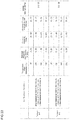
- FIG. 7 is a composition chart of Examples and Comparative Examples of the present disclosure.
- FIG. 8 is a chart showing the magnetic property of examples of the present disclosure.
- FIG. 9 is a chart showing the magnetic property of examples of the present disclosure.
- FIG. 10 is a chart showing the magnetic property of examples of the present disclosure.
- FIG. 11 is an SEM photograph of a needle-like substance obtained by processing an example of the present disclosure.
- FIG. 12 is a 3D atomic image of the needle-like substance obtained by processing an example of the present disclosure.
- FIG. 13 is an analysis result of the crystal structure by 3DAP according to an example of the present disclosure.
- FIG. 14 is an analysis result of the crystal structure by the 3DAP according to an example of the present disclosure.
- FIG. 15 is an analysis result of the crystal structure by the 3DAP according to an example of the present disclosure.
- FIG. 16 is a model diagram of the crystal structure of a main phase of the rare earth permanent magnet according to the present disclosure.
- FIG. 17 is an analysis result of the crystal structure by the 3DAP according to an example of the present disclosure.
- FIG. 18 is an analysis result of the crystal structure by the 3DAP according to an example of the present disclosure.
- FIG. 19 is an analysis result of the crystal structure by the 3DAP according to an example of the present disclosure.
- FIG. 20 is an analysis result of the crystal structure by the 3DAP according to an example of the present disclosure.
- FIG. 21 is an analysis result of the crystal structure by the 3DAP according to an example of the present disclosure.
- FIG. 22 is an analysis result of the crystal structure by the 3DAP according to an example of the present disclosure.
- FIG. 23 is an analysis result of the crystal structure by the 3DAP according to an example of the present disclosure.
- FIG. 24 is an analysis result of the crystal structure by the 3DAP according to an example of the present disclosure.
- FIG. 25 is an analysis result of the crystal structure by the 3DAP according to an example of the present disclosure.
- FIG. 26 is an analysis result of the crystal structure by the Rietveld method according to an example of the present disclosure.
- FIG. 27 is an analysis result of the crystal structure by the Rietveld method according to an example of the present disclosure.
- FIG. 28 is a chart showing the magnetic property of examples of the present disclosure.
- FIG. 29 is a chart showing the magnetic property of examples of the present disclosure.
- FIG. 30 is an analysis result of the crystal structure by the Rietveld method according to an example of the present disclosure.
- FIG. 31 is an analysis result of the crystal structure by the Rietveld method according to an example of the present disclosure.
- FIG. 32 is a chart showing the magnetic property of examples of the present disclosure.
- FIG. 33 is a chart showing the magnetic property of examples of the present disclosure.
- FIG. 34 is an analysis result of the crystal structure by the Rietveld method according to an example of the present disclosure.
- FIG. 35 is an analysis result of the crystal structure by the Rietveld method according to an example of the present disclosure.
- FIG. 36 is a chart showing the magnetic property of examples of the present disclosure.
- FIG. 37 is a chart showing the magnetic property of examples of the present disclosure.
- FIG. 38 is an analysis result of the crystal structure by the Rietveld method according to an example of the present disclosure.
- FIG. 39 is an analysis result of the crystal structure by the Rietveld method according to an example of the present disclosure.
- FIG. 40 is a chart showing the magnetic property of examples of the present disclosure.
- FIG. 41 is a chart showing the magnetic property of examples of the present disclosure.
- FIG. 42 is an analysis result of the crystal structure by the Rietveld method according to an example of the present disclosure.
- FIG. 43 is an analysis result of the crystal structure by the Rietveld method according to an example of the present disclosure.
- FIG. 44 is a chart showing the magnetic property of examples of the present disclosure.
- FIG. 45 is a chart showing the magnetic property of examples of the present disclosure.
- FIG. 46 is a chart showing the magnetic property of examples of the present disclosure.
- FIG. 47 is a chart showing the magnetic property of examples of the present disclosure.
- FIG. 48 is a chart showing the state after a heat treatment in Comparative Examples of the present disclosure.
- FIG. 3( a ) indicates a left graph of FIG. 3
- FIG. 3( b ) indicates a right graph of FIG. 3
- FIG. 4( a ) indicates a left graph of FIG. 4
- FIG. 4( b ) indicates a right graph of FIG. 4
- FIG. 5( a ) indicates a left graph of FIG. 5
- FIG. 5( b ) indicates a right graph of FIG. 5 , respectively.
- FIG. 3( a ) is a diagram illustrating an electron density of states of the whole crystal of the Nd 2 Fe 14 B particles obtained by the inventors of the present disclosure.
- FIG. 3( b ) is a diagram illustrating a partial electron density of states at d orbitals and f orbitals of entire Fe atoms and Nd atoms in the relevant crystal. Waveforms of the electron density of states indicated in FIG. 3( a ) and FIG. 3( b ) are closely similar to each other.
- Fe accounts for approximately 70 at % of the Nd 2 Fe 14 B particles. Magnetism of the Nd 2 Fe 14 B particles derives from Fe and it is believed that Nd contributes to magnetic expression of the particles by aligning a spin direction of Fe.
- FIG. 3( a ) and FIG. 3( b ) coincide with the above-described findings.
- FIG. 4( a ) is a diagram illustrating a sum of partial electron density of states of s orbitals, p orbitals, and d orbitals of B—Fe nearest neighbor atoms in the Nd 2 Fe 14 B particles obtained by the inventors of the present disclosure.
- FIG. 4( b ) is a diagram illustrating a partial electron density of states at the p orbitals and d orbitals of the B—Fe nearest neighbor atoms.
- first principle calculation software CASTEP made by Accelrys
- the distance between the above-mentioned B and Fe nearest neighbor atoms was 2.09 ⁇ . It was confirmed by referring to FIG. 4( b ) that the p orbitals of boron were polarized.
- the inventors of the present disclosure calculated a local electron density of states at s orbitals and p orbitals of B atoms in the Nd 2 Fe 14 B particles and obtained the results shown in FIG. 5( a ) and FIG. 5( b ) . It was confirmed by referring to FIG. 5( a ) and FIG. 5( b ) that the B atoms were polarized at both the s orbitals and the p orbitals.
- Table 1 is a table of magnetic moments calculated based on atomic locations obtained by a neutron diffraction method (O. Isnard et. al J. Appl. Phys. 78 (1995) 1892-1898). Table 1 shows that the magnetic moment of the ND atoms in the Nd 2 Fe 14 B particles is less than 4 ⁇ B and the magnetic moment is small. It is presumed that one of the reasons for such reduction of the magnetic moment would be covalent bondings between the Nd atoms and the B atoms in the crystal structure of the relevant particles and donation of part of f electrons in the Nd atoms to the s orbitals of the boron atoms. As a result, it is believed that the Nd atoms in the particles lose their magnetism.
- the inventors of the present disclosure obtained findings that the B atoms are polarized and are involved in suppression of magnetism of the Nd 2 Fe 14 B particles. Based on such findings, the inventors of the present disclosure conceived the idea of enhancing the magnetism of the particles by substituting the B atoms with other atoms in the crystal of the Nd 2 Fe 14 B particles.
- the rare earth permanent magnet of the present disclosure has a compound represented by an expression (1) indicated below as a main phase.
- the number of atoms in the relevant compound in a unit lattice accounts for 90 to 98 at % of the number of atoms of the entire particles.
- the present disclosure permits the main phase to contain impurities which are not the above-described compound.
- M represents an element selected from any one of cobalt, beryllium, lithium, aluminum, and silicon. Furthermore, x satisfies 0.01 ⁇ x ⁇ 0.25, and more preferably 0.03 ⁇ x ⁇ 0.25.
- the present disclosure is composed so that part of boron in the conventional Nd 2 Fe 14 B crystal is substituted with a specified element. Accordingly, the present disclosure can inhibit transfer of f electrons of neodymium to other atoms. Therefore, the number of unpaired electrons of neodymium can be easily maintained and the magnetic moment of the Nd atoms can be enhanced as compared to the conventional crystal.
- the magnetic moment reduces. In a case of x>0.25, the crystal structure cannot be maintained, so that synthesis cannot be performed.
- the present disclosure is designed so that part of boron contained in the main phase is substituted with one or more atoms selected from a group consisting of cobalt, beryllium, lithium, aluminum, and silicon. Accordingly, the present disclosure inhibits reduction of unpaired electrons and enhances the magnetic property.
- the present disclosure may be composed so that part of boron and part of iron in the conventional Nd 2 Fe 14 B crystal are substituted with a specified element.
- Such a composition can be represented by the following expression (2). [Chem. 4] Nd 2 Fe (14-y) L y B (1-x) M x (2)
- M and L are elements selected from any one of cobalt, beryllium, lithium, aluminum, and silicon
- y is 0 ⁇ y ⁇ 2
- x is 0.0 ⁇ x ⁇ 0.25
- x and y satisfy 0.01 ⁇ (x+y) ⁇ 2.25. More preferably, y is 0.1 ⁇ y ⁇ 1.2
- x is 0.02 ⁇ x ⁇ 0.25, and x and y satisfy 0.12 ⁇ (x+y) ⁇ 1.45.
- the magnetic moment of the Nd atoms can be enhanced as compared to the conventional crystal. Furthermore, the magnetic moment of the Fe atoms can be enhanced based on conventionally-known findings.
- the magnetic moment of the iron atoms reduces. In a case of x ⁇ 0.01 or x>0.25, the magnetic moment of the neodymium atoms reduces. When x, y, and x+y are out of their respective specified ranges, the magnetic moments of the iron atoms and the neodymium atoms reduce.
- the magnetic moment of the Nd atoms contained in that compound is larger than the magnetic moment of the Nd atoms in the Nd 2 Fe 14 B crystal.
- the magnetic moment of the Nd atoms according to the present disclosure is at least larger than 2.70 ⁇ B and should preferably be 3.75 to 3.85 ⁇ B , and more preferably 3.80 to 3.85 ⁇ B .
- the present disclosure is designed to cause the magnetism of the Nd atoms to be expressed, it has a better magnetic property than magnetism derived from the Fe atoms and the Nd atoms.
- the magnetic property of the present disclosure can be evaluated based on the coercive force H cj and the residual magnetic flux density Br.
- the magnetic property of the present disclosure is enhanced by 40 to 50% as compared to the rare earth permanent magnet composed of the conventional Nd 2 Fe 14 B crystal.
- the compound constituting the main phase of the present disclosure contains any one or more types of elements selected from a group consisting of cobalt, beryllium, lithium, aluminum, and silicon and contains neodymium, iron, and boron.
- FIG. 1 and FIG. 2 show schematic views of examples of the crystal structures represented by the aforementioned expression (1) and expression (2), respectively.
- FIG. 1 is a schematic view illustrating an example of the crystal structure of the present disclosure as represented by the expression (1).
- the relevant compound has a basic skeleton composed of Fe and an Fe layer 101 and an Nd—B-M layer 102 exist alternately in the z-axis direction.
- the Nd—B-M layer 102 contains neodymium (Nd), boron (B), and element M and interstices 103 exist.
- an element whose wave function fits in the relevant interstice 103 and which has a smaller atomic radius than that of boron for example, any one cobalt, beryllium, lithium, aluminum, and silicon, is selected as appropriate.
- any one or more elements of cobalt, beryllium, lithium, aluminum, and silicon should preferably be selected. Cobalt is more preferable.
- Part of B can be naturally substituted with another element M by sintering an alloy of the above-described content ratio.
- the present disclosure exhibits a high magnetic moment and a good magnetic property.
- FIG. 2 is a schematic view illustrating an example of the crystal structure of the present disclosure as represented by the expression (2).
- the relevant compound has a basic skeleton composed of the Fe atoms and L atoms and an Fe-L layer 201 and an Nd—B-M layer 202 exist alternately in the z-axis direction.
- the Nd—B-M layer 202 contains neodymium (Nd), boron (B), and M atoms and interstices 203 exist.
- any element whose atomic radius is extremely larger than that of the iron atoms can hardly be selected as the element L.
- the wave functions of atoms in the elements are appropriately superimposed on each other, the relevant atoms in the elements may be easily substituted for the iron atoms in the crystal.
- An explanation about the element M as illustrated in FIG. 2 is the same as the aforementioned explanation about the element M as illustrated in FIG. 1 .
- any one or more of cobalt, beryllium, lithium, aluminum, and silicon should preferably be selected as the element M and the element L in the expression (2) which satisfies the above-described conditions. Cobalt is more preferable. Normally the same element is selected as M and L, but different elements may be selected as M and L. From the viewpoint of simplifying a manufacturing process, the same element should preferably be selected. From the viewpoint of enhancing the magnetic moment of the Fe atoms, at least the cobalt should preferably be selected as M.
- the compound represented by the expression (2) contains the element M by 1 to 25 at % relative to the number of Nd atoms in the relevant compound particulates, electrons donated from the Nd atoms to the B atoms in the compound are reduced, thereby making it possible to enhance the magnetic moment of the Nd atoms. As a result, the present disclosure exhibits a high magnetic moment and a good magnetic property.
- the rare earth permanent magnet of the present disclosure has the Nd—Fe—B layer and the Fe layer periodically and part of boron contained in the Nd—Fe—B layer is substituted with any one or more types of elements selected from a group consisting of cobalt, beryllium, lithium, aluminum, and silicon.
- FIG. 16 is a model diagram illustrating the crystal structure of the main phase of the rare earth permanent magnet of the present disclosure which was obtained by analyzing an example of the present disclosure by a Three Dimensional Atom Probe (3DAP). The details of the example and its analysis method will be explained later.
- 500 represents a unit lattice of the main phase
- 501 represents an Fe layer
- 502 represents an Nd—Fe—B layer.
- FIG. 16 shows that the Fe layer 501 and the Nd—Fe—B layer 502 exist alternately.
- the analysis result by the Rietveld method described later indicates that cobalt atoms exist at sites where the B atoms of the Nd—Fe—B layer in the conventional Nd 2 Fe 14 B crystal exist.
- the Nd—Fe—B layer should preferably contain terbium. Furthermore, the Nd—Fe—B layer should preferably contain any one or more types of elements of praseodymium and dysprosium. An aspect where terbium, praseodymium, and dysprosium exist at whatever sites in the Nd—Fe—B layer also falls under the crystal structure of the main phase according to the present disclosure. Specifically speaking, each one of terbium, praseodymium, and dysprosium may be substituted with Nd or Fe and may enter the interstices.
- the main phase contains neodymium, iron, and boron and further contains any one or more types of elements selected from a group consisting of cobalt, beryllium, lithium, aluminum, and silicon.
- the rare earth permanent magnet of the present disclosure contains iron as its main constituent more than any other constituents and the content of iron is sometimes expressed as the remainder relative to the other constituents.
- the content of neodymium should preferably be 20 to 35 wt % and more preferably 22 to 33 wt %.
- the content of boron should preferably be 0.80 to 0.99 wt % and more preferably 0.82 to 0.98 wt %.
- the total content of any one or more types of elements selected from a group consisting of cobalt, beryllium, lithium, aluminum, and silicon is 0.8 to 1.0 wt %. As a result, the present disclosure can obtain a good residual magnetic flux density Br.
- the present disclosure should preferably contain terbium in addition to the above-described constituents.
- the present disclosure can enhance the coercive force H cj of the rare earth permanent magnet by containing terbium in addition to any one or more types of elements selected from a group consisting of cobalt, beryllium, lithium, aluminum, and silicon.
- the compound containing terbium can be represented by the following expression (3) or expression (4).
- M represents an element selected from any one of cobalt, beryllium, lithium, aluminum, and silicon
- x satisfies 0.01 ⁇ x ⁇ 0.25
- z satisfies 1 ⁇ z ⁇ 1.8.
- the magnetic moment of the neodymium atoms reduces.
- the crystal structure becomes unstable.
- this causes a reduction of holding force.
- the residual magnetic flux density reduces.
- each of M and L is an element selected from any one of cobalt, beryllium, lithium, aluminum, and silicon
- y is 0 ⁇ y ⁇ 2
- x is 0.01 ⁇ x ⁇ 0.25
- x and y satisfy 0.01 ⁇ (x+y) ⁇ 2.25.
- z is 1 ⁇ z ⁇ 1.8.
- the rare earth permanent magnet of the present disclosure containing the terbium contains the iron as its main constituent more than any other constituents and the content of iron is sometimes expressed as the remainder relative to the other constituents.
- the content of neodymium should preferably be 20 to 35 wt % and more preferably 22 to 33 wt %.
- the content of boron should preferably be 0.80 to 0.99 wt % and more preferably 0.82 to 0.98 wt %.
- the total content of any one or more types of elements selected from a group consisting of cobalt, beryllium, lithium, aluminum, and silicon is 0.8 to 1.0 wt %.
- the content of terbium is 2.0 to 10.0 wt % and more preferably 2.5 to 4.5 wt %. As a result, the present disclosure can obtain a good residual magnetic flux density Br.
- the present disclosure contains neodymium, iron, and boron and further contains any one or more types of elements selected from a group consisting of cobalt, beryllium, lithium, aluminum, and silicon and contains terbium, it has a magnetic property that that satisfies any one or more conditions of a group consisting of mc1 and mc2 at a temperature condition of 20° C.
- Mc1 represents the magnetic property indicating that the residual magnetic flux density Br is 12.90 kG or more.
- the residual magnetic flux density Br should more preferably be 13.00 kG or more as mc1.
- Mc2 represents the magnetic property indicating that the coercive force H cj is 27.90 kOe or more.
- the coercive force H cj should more preferably be 28.20 kOe or more as mc2.
- any magnetic property of the present disclosure can be measured by using a pulse-excitation-type magnetic property measurement apparatus with a specimen temperature variator which is conventionally known.
- the present disclosure containing the above-mentioned elements has a magnetic property that satisfies any one or more conditions of a group consisting of mc3 and mc4 at a temperature condition of 100° C.
- Mc3 represents the magnetic property indicating that the residual magnetic flux density Br is 11.80 kG or more.
- the residual magnetic flux density Br should more preferably be 11.85 kG or more as mc3.
- Mc4 represents the magnetic property indicating that the coercive force H cj is 17.40 kOe or more.
- the coercive force H cj should more preferably be 18.20 kOe or more as mc4.
- the present disclosure containing the above-mentioned elements has a magnetic property that satisfies any one or more conditions of a group consisting of mc5 and mc6 at a temperature condition of 160° C.
- Mc5 represents the magnetic property indicating that the residual magnetic flux density Br is 10.80 kG or more.
- the residual magnetic flux density Br should more preferably be 10.95 kG or more as mc5.
- Mc6 represents the magnetic property indicating that the coercive force H cj is 10.50 kOe or more.
- the coercive force H cj should more preferably be 11.00 kOe or more as mc6.
- the present disclosure containing the above-mentioned elements has a magnetic property that satisfies any one or more conditions of a group consisting of mc7 and mc8 at a temperature condition of 200° C.
- Mc7 represents the magnetic property indicating that the residual magnetic flux density Br is 10.10 kG or more.
- the residual magnetic flux density Br should more preferably be 10.14 kG or more as mc7.
- Mc8 represents the magnetic property indicating that the coercive force H cj is 6.60 kOe or more.
- the coercive force H cj should more preferably be 6.90 kOe or more as mc8.
- both the residual magnetic flux density Br and the coercive force H cj are good.
- the magnetic property of this present disclosure does not degrease even at a temperature condition higher than a room temperature.
- the present disclosure may contain elements, such as praseodymium and dysprosium, that contributes to enhancement of the magnetic property. It is possible to manufacture the rare earth permanent magnet of the present disclosure, which exhibits the excellent magnetic property, at low cost by containing the praseodymium.
- the praseodymium contained in the present disclosure is mainly substituted with neodymium. It can also be dispersed in other areas within the crystal structure.
- the ratio of neodymium to praseodymium contained in the present disclosure on a basis of the number of atoms is 80:20 to 70:30.
- a proportion of the praseodymium should be larger and a proportion of the neodymium should be smaller; however, if the proportion of the neodymium becomes less than 70 on the basis of the above-described ratio of the number of atoms, the possibility of decrease of the residual magnetic flux density Br increases.
- dysprosium contained in the present disclosure is substituted for the iron.
- the dysprosium may be used solely as a substituent element of the iron or together with the terbium.
- the elements such as terbium and praseodymium may be dispersed in other areas within the crystal structure.
- the compound containing praseodymium and dysprosium can be represented by the following expression (5) or expression (6).
- M represents an element selected from any one of cobalt, beryllium, lithium, aluminum, and silicon and x satisfies 0.01 ⁇ x ⁇ 0.25.
- R1 represents praseodymium and R2 represents any one or more types of elements of terbium and dysprosium.
- x, z, z1, and z2 are out of the above-described ranges, the residual magnetic flux density and the coercive force decrease.
- M and L represent elements selected from any one of cobalt, beryllium, lithium, aluminum, and silicon
- y is 0 ⁇ y ⁇ 2
- x is, 0.01 ⁇ x ⁇ 0.25, and x and y satisfy 0.01 ⁇ (x+y) ⁇ 2.25.
- Z is 1 ⁇ z ⁇ 1.8.
- R1 represents praseodymium and R2 represents any one or more types of elements of terbium and dysprosium.
- the main phase of the present disclosure has crystals containing neodymium, iron, and boron and containing any one or more types of elements selected from a group consisting of cobalt, beryllium, lithium, aluminum, and silicon.
- a sintered particle size D 50 of the crystals should preferably be 2 to 25 ⁇ m, more preferably 3 to 15 ⁇ m, and further more preferably 3 to 11 ⁇ m. Particularly when the crystals are refined to 3 to 6 ⁇ m, the obtained particles are preferable because they exhibit a good magnetic property even if the content of terbium is reduced.
- D 50 is a median diameter in cumulative distribution of an alloy particulate group on a volume basis. D 50 can be measured by known methods using a laser-diffraction-type particle-size distribution measuring apparatus. All numerical values indicating the “powder particle size,” “sintered particle size,” and “particle size” are D 50 .
- a raw material alloy used for the present disclosure forms crystals which become the main phase by a heat treatment step.
- the sintered particle size D 50 of such crystals is 110 to 300%, more specifically 110 to 180%, of the powder particle size D 50 of the raw material alloy.
- An example of a method for forming the crystals whose sintered particle size is within the above-described preferable range can include a method of molding the raw material alloy of an appropriate power particle size corresponding to the desired sintered particle size, magnetizing the raw material alloy, and applying a heat treatment to the raw material alloy.
- the powder particle size can be adjusted by known methods by using, for example, a ball mill or a jet mill.
- the sintered density of the main phase becomes higher, the residual magnetic flux density becomes larger. Therefore, the sintered density should preferably be 6.0 g/cm 3 or more and a larger sintered density of 7.5 g/cm 3 or more is more preferable.
- the sintered density is determined based on the powder particle size of the raw material alloy, and a processing temperature, a sintering temperature, and an aging temperature in the heat treatment step. Therefore, according to the present disclosure, because of the raw material alloy which can be prepared and conditions of the heat treatment step, the sintered density is 6.0 to 8.0 g/cm 3 , more preferably 7.0 to 7.9 g/cm 3 , and further preferably 7.2 to 7.7 g/cm 3 . When the sintered density is less than 7.0 g/cm 3 , it is inappropriate for a magnet.
- the present disclosure contains neodymium, iron, and boron, further contains any one or more types of elements selected from a group consisting of cobalt, beryllium, lithium, aluminum, and silicon, contains terbium, and additionally contains any one or more types of praseodymium and dysprosium, it has a magnetic property that satisfies any one or more conditions of a group consisting of mc9 and mc10 at a temperature condition of 20° C.
- Mc9 represents the magnetic property indicating that the residual magnetic flux density Br is 12.50 kG or more.
- the residual magnetic flux density Br should more preferably be 13.20 kG or more as mc9.
- Mc10 represents the magnetic property indicating that the coercive force H cj is 21.20 kOe or more.
- the coercive force H cj should more preferably be 29.50 kOe or more as mc10.
- the present disclosure containing the above-described elements has a magnetic property that satisfies any one or more conditions of a group consisting of mc11 and mc12 at a temperature condition of 100° C.
- Mc11 represents the magnetic property indicating that the residual magnetic flux density Br is 11.60 kG or more.
- the residual magnetic flux density Br should more preferably be 12.30 kG or more as mc11.
- Mc12 represents the magnetic property indicating that the coercive force H cj is 11.80 kOe or more.
- the coercive force H cj should more preferably be 18.00 kOe or more as mc12.
- the present disclosure containing the above-described elements has a magnetic property that satisfies any one or more conditions of a group consisting of mc13 and mc14 at a temperature condition of 160° C.
- Mc13 represents the magnetic property indicating that the residual magnetic flux density Br is 10.60 kG or more.
- the residual magnetic flux density Br should more preferably be 11.20 kG or more as mc13.
- Mc14 represents the magnetic property indicating that the coercive force H cj is 6.20 kOe or more.
- the coercive force H cj should more preferably be 10.00 kOe or more as mc14.
- the present disclosure containing the above-described elements has a magnetic property that satisfies any one or more conditions of a group consisting of mc15 and mc16 at a temperature condition of 200° C.
- Mc15 represents the magnetic property indicating that the residual magnetic flux density Br is 9.60 kG or more. The residual magnetic flux density Br should more preferably be 10.30 kG or more as mc15.
- Mc16 represents the magnetic property indicating that the coercive force H cj is 3.80 kOe or more. The coercive force H cj should more preferably be 6.00 kOe or more as mc16.
- both the residual magnetic flux density Br and the coercive force H cj are good.
- the magnetic property of this disclosure does not decrease even at a temperature condition higher than a room temperature.
- the rare earth permanent magnet of the present disclosure containing any one or more types of elements selected from a group consisting of praseodymium, terbium, dysprosium, and so on contains iron as its main constituent more than any other constituents and the content of iron is sometimes expressed as the remainder relative to the other constituents.
- the content of neodymium should preferably be 15 to 40 wt % and more preferably 20 to 35 wt %.
- the content of praseodymium is 5 to 20 wt % and more preferably 5 to 15 wt %.
- the content of boron should preferably be 0.80 to 0.99 wt % and more preferably 0.82 to 0.98 wt %.
- the total content of any one or more types of elements selected from a group consisting of cobalt, beryllium, lithium, aluminum, and silicon is 0.8 to 1.0 wt %.
- the content of any one or more types of elements of terbium and dysprosium is 2.0 to 10.0 wt % and more preferably 2.5 to 4.5 wt %. As a result, the present disclosure can obtain a good residual magnetic flux density Br.
- the present disclosure should preferably include a grain boundary phase containing any one or more types of elements selected from a group consisting of aluminum, copper, niobium, zirconium, titanium, and gallium.
- the elements which form the grain boundary phase can be also dispersed in the main phase as appropriate. Since the amount of dispersion is very small, it is not reflected in the preferable content of each constituent in the above-described main phase.
- FIG. 6 is a schematic illustration showing an example of the microstructure of the present disclosure.
- 300 represents the main phase and 400 represents the grain boundary phase.
- spin electrons of constituents of the grain boundary phase pin spin electrons of main constituents, thereby promoting spin reverse of the main phase constituents.
- the grain boundary phase disconnects a magnetic exchange coupling of the main phase. As a result, it is possible to enhance the coercive force H cj .
- the content of aluminum should be 0.1 to 0.4% and the content of copper should be 0.01 to 0.1%. More preferably, the content of aluminum should be 0.2 to 0.3% and the content of copper should be 0.02 to 0.09%.
- a preferable content of zirconium by percent by weight relative to the total weight of the rare earth permanent magnet should be 0.004 to 0.04% and more preferably 0.01 to 0.04%.
- the iron is contained as its main constituent more than any other constituents and the content of iron is sometimes expressed as the remainder relative to the other constituents.
- the content of other constituents relative to the total weight of the present disclosure by percent by weight it is preferable that the content of neodymium should be 20 to 35%, the content of boron should be 0.80 to 0.99%, the total amount of any one or more types of elements selected from a group consisting of cobalt, beryllium, lithium, aluminum, and silicon should be 0.8 to 1.0%, and the content of terbium should be 2.0 to 10.0%; and in addition to the above constituents, the content of aluminum should be 0.1 to 0.4% and the consent of copper should be 0.01 to 0.1%.
- the constituents other than the iron as described above by percent by weight it is preferable that at least the content of neodymium should be 22 to 33%, the content of boron should be 0.82 to 0.98%, the total amount of any one or more types of elements selected from a group consisting of cobalt, beryllium, lithium, aluminum, and silicon should be 0.8 to 1.0%, and the content of terbium should be 2.6 to 5.4%; and in addition to the above constituents, the content of aluminum should be 0.2 to 0.3% and the content of copper should be 0.02 to 0.09%.
- the content of neodymium should be 15 to 40 wt %
- the content of praseodymium should be 5 to 20 wt %
- the content of terbium should be 2.0 to 10.0 wt %
- the content of boron should be 0.80 to 0.99 wt %
- the total amount of any one or more types of elements selected from a group consisting of cobalt, beryllium, lithium, aluminum, and silicon should be 0.8 to 1.0 wt %
- the content of aluminum should be 0.1 to 0.4 wt % and the content of copper should be 0.01 to 0.1 wt %.
- the present disclosure exhibits excellent heat resistance and has a high residual magnetic flux density Br, a high coercive force H cj , and a large maximum energy product BH max even under the high-temperature condition.
- the magnetic property of the present disclosure regarding which the sintered particle size D 50 of the main phase is 3 to 11 ⁇ m is summarized below by each temperature condition. Incidentally, the magnetic property described below can be further enhanced by refining the crystal particle size of the main phase.
- the residual magnetic flux density Br is distributed at 11.40 kG or more, preferably at 12.50 kG or more, and more preferably at 12.90 kG or more.
- the coercive force H cj is distributed at 21.20 kOe or more, and preferably at 27.90 kOe or more.
- the maximum energy product BH max is distributed at 31.00 MGOe or more, and more preferably at 40.10 MGOe or more.
- the residual magnetic flux density Br is distributed at least at approximately 10.00 to 12.00 kG.
- the residual magnetic flux density Br should preferably be distributed at 10.60 kG or more, and more preferably at 11.80 kG or more.
- the coercive force H cj is distributed at 11.80 kOe or more and at 17.00 to 19.00 kOe.
- the coercive force H cj should preferably be distributed at 17.40 kOe or more.
- the maximum energy product BH max is distributed at least at 33.00 to 35.00 MGOe.
- the maximum energy product BH max should preferably be distributed at 27.10 MGOe or more, more preferably at 36.80 MGOe or more.
- the residual magnetic flux density Br is distributed at least at approximately 9.000 to 11.00 kG. In addition, the residual magnetic flux density Br should preferably be distributed at 9.80 kG or more, and more preferably at 10.80 kG or more.
- the coercive force H cj is distributed at 6.200 kOe or more and at 11.00 to 12.00 kOe. The coercive force H cj should preferably be distributed at 10.50 kOe or more.
- the maximum energy product BH max is distributed at least at 27.00 to 29.00 MGOe. In addition, the maximum energy product BH max should preferably be distributed at 22.75 MGOe or more, more preferably at 27.80 MGOe or more.
- the residual magnetic flux density Br is distributed at 9.00 kG or more, preferably at 9.90 to 11.00 kG, more preferably at 9.60 kG or more, and more preferably at 10.10 kG or more.
- the coercive force H cj is distributed at 3.80 kOe or more and at approximately 6.50 to 7.00 kOe.
- the coercive force H cj should preferably be distributed at 6.60 kOe or more, and more preferably 15.90 kOe or more.
- the maximum energy product BH max is distributed at least at 22.90 to 24.00 MGOe. In addition, the maximum energy product BH max should preferably be distributed at 19.00 MGOe or more, more preferably at 23.70 MGOe or more.
- the present disclosure has high mechanical strength.
- Tensile strength of the rare earth permanent magnet of the present disclosure is 80 MPa or more, preferably 100 MPa or more, and more preferably 150 MPa or more.
- the present disclosure has excellent machinability and can enhance mass productivity of products which use the present disclosure. It is also possible to enhance the products' life cycle.
- the tensile strength of the present disclosure can be measured by methods according to JIS Z2201 (tension test specimen processing method) and JIS Z2241 (tensile test measurement method).
- the method for manufacturing the rare earth permanent magnet according to the present disclosure is not particularly limited as long as the function effects of the present disclosure can be obtained.
- An example of a preferable manufacturing method according to the present disclosure can be a manufacturing method including a microparticulation step, a magnetization step, and a heat treatment step.
- the rare earth permanent magnet of the present disclosure can be manufactured by cooling a product, which is obtained as a result of each of the above-described steps, down to a room temperatures in a cooling step.
- specified materials such as Co and Fe, Nd, and B are dissolved at the stoichiometric ratio explained above, thereby obtaining a raw material alloy.
- specified materials such as Co and Fe, Nd, and B are dissolved at the stoichiometric ratio explained above, thereby obtaining a raw material alloy.
- starting materials containing these elements are added as raw materials when manufacturing the above-described raw material alloy.
- the stoichiometric ratio of the composition of the raw material alloy is almost the same as the composition of the compound which becomes the main phase of the present disclosure that is a final product. Therefore, it is only necessary to combine the raw materials according to the composition of the desired compound.
- the obtained raw material alloy is coarsely ground by using, for example, a ball mill or a jet mill. It is also preferable that particulates of the raw material alloy which are then obtained by coarse grinding should be refined by using, for example, the ball mill or the jet mill.
- the coarsely-ground raw material alloy particles are dispersed in an organic solvent and a reducing agent is added to the obtained product.
- a reducing agent is added to the obtained product.
- the raw material alloy particles are atomized and its particle size becomes a powder particle size of 1.8 to 22.7 ⁇ m.
- the reduction processing is executed on the microparticulated raw material alloy particles, the powder particle size becomes much smaller to 2.7 to 13.6 ⁇ m, more specifically 2.7 to 10.0 ⁇ m.
- the obtained raw material alloy particulates are compression-molded in an oriented magnetic field. Furthermore, in the heat treatment step, the obtained molded body is heated under vacuum and then the obtained sinter is rapidly cooled to a room temperature. Subsequently, the heat treatment step is conducted under an inert gas atmosphere and then the sinter is cooled down to a room temperature.
- the main phase and the grain boundary phase are formed by conducting specified temperature management and time management.
- the heat treatment conditions are determined based on melting points of the constituents. Specifically speaking, all the constituents are dissolved by increasing the processing temperature to a main-phase-forming temperature and maintaining that temperature. Then, in the process of decreasing the temperature from the main-phase-forming temperature to a grain-boundary-phase-forming temperature, the main phase constituents enter a solid phase and the grain boundary phase constituents start depositing on a solid phase surface.
- the grain boundary phase can be formed by maintaining the grain-boundary-phase-forming temperature.
- the temperature should preferably be retained at 1000 to 1200° C. for 3 to 5 hours and then further retained at 880 to 920° C. for 4 to 5 hours. More preferably, the temperature should be retained at 1010 to 1190° C. for 3 to 5 hours and then further retained at 890 to 910° C. for 3 to 5 hours.
- the temperature should preferably be retained at 480 to 520° C. for 3 to 5 hours and then further retained at 490 to 510° C. for 3 to 5 hours.
- the present disclosure can be manufactured by executing at least each of the above-described steps.
- the present disclosure can manufacture the rare earth permanent magnet by applying the conventionally-known method for manufacturing the rare earth permanent magnet only by using the alloy, in which Nd, Pr, Tb, etc. and Fe, B, Co, etc. of the specified content described earlier are dissolved, as raw materials. Furthermore, when manufacturing the rare earth permanent magnet which includes the specified main phase and grain boundary phase, the rare earth permanent magnet of the present disclosure can be manufactured easily by applying the above-explained heat treatment step.
- the powder particle size of the raw material compound should preferably be 1.8 to 22.7 ⁇ m.
- the powder particle size of more preferably 2.7 to 13.6 ⁇ m, and further preferably 2.7 to 10.0 ⁇ m and retaining the raw material compound at the main-phase-forming temperature the rare earth permanent magnet with an excellent magnetic property can be manufactured even if the content of terbium is suppressed.
- the sintered particle size of the raw material compound becomes 110 to 300%, or preferably 110 to 180%, of the powder particle size.
- the sintered particle size becomes 2 to 25 ⁇ m, preferably 3 to 15 ⁇ m, more preferably 3 to 11 ⁇ m, and particularly preferably 3 to 6 ⁇ m.
- the rare earth permanent magnet of the present disclosure having the main phase of the crystals of the above-described sintered particle size decreases the content of terbium by 20 to 30% and has an equivalent magnetic property.
- such power particle size can be obtained by grinding the crystals by using the jet mill or the ball mill.
- a sintered density of the alloy compound which includes the crystals of the above-described preferable sintered particle size as the main phase becomes 6 to 8 g/cm 3 , and more preferably 7.2 to 7.9 g/cm 3 .
- a method for measuring the sintered density will be described below. The weight used for measurement of the sintered density was measured by measuring samples with an electronic scale. Furthermore, the volume was found by the Archimedean Method or by measuring the dimensions of the samples with a ruler.
- Co Cobalt
- Nd Nd
- Fe Fe
- B Cobalt
- the obtained 5 kg alloy was coarsely ground with the ball mill, thereby obtaining alloy particles with an average particle diameter of 16 ⁇ m.
- the alloy particles was dispersed in a solvent.
- An additive was introduced into the dispersed solution, which was then stirred to cause a reduction reaction to refine the alloy particles.
- An average particle diameter of the obtained fine alloy powder was 16 to 25 ⁇ m.
- the same process can be conducted on any one type of metal from among beryllium (Be), lithium (Li), aluminum (Al), and silicon (Si) besides cobalt (Co).
- Respective samples of the above-described fine alloy powder were used as raw material compounds 1 to 5 and their magnetic moments were calculated by referring to atomic locations obtained by a neutron diffraction method (O. Isnard et. al J. Appl. Phys. 78 (1995) 1892-1898).
- Table 2 shows the magnetic moments of the raw material compounds 1 to 5.
- a molding cavity was filled with 500 g of the raw material compound (the raw material compound 1) which used cobalt (Co), a 19 kOe magnetic field with a molding pressure of 2 t/cm 2 was applied to conduct compression molding and magnetization.
- the obtained molded body was heated at a treatment temperature of 1090° C. for one hour under a 2 ⁇ 10 1 Torr Ar gas atmosphere. After the heat treatment terminated, the temperature was cooled down to a room temperature, and then the obtained product was removed from the cavity, thereby obtaining a rare earth permanent magnet of Example 1.
- Rare earth permanent magnets of Examples 2 to 5 for which any one type of metals from among beryllium (Be), lithium (Li), aluminum (Al), and silicon (Si) was used can be obtained in the same manner.
- the raw material alloy containing the respective elements with the content indicated in FIG. 7 was ground, thereby obtaining alloy particles. Subsequently, the alloy particles were dispersed in a solvent. An additive was introduced to the dispersed solution, which was then stirred to cause a reduction reaction, thereby refining the alloy particles.
- An average particle diameter of the alloy particulates of Example 6 and Example 9 was 16 to 25 ⁇ m.
- the average particle diameter (powder particle size) of the alloy particulates of Example 7, Example 8, and Example 10 to Example 12 was 3 to 11 ⁇ m.
- the average particle diameter was measured with an apparatus equivalent to a laser-diffraction-type particle-size distribution measuring apparatus SALD-2300 made by SHIMADZU CORPORATION.
- the molding cavity was filled with 500 g of the obtained alloy particulates 500 g and a 19 kOe magnetic field with a molding pressure of 2 t/cm 2 was applied to the alloy particulates of each example to conduct compression molding and magnetization.
- a heat treatment was applied to each obtained molded body under a 2 ⁇ 10 1 Torr Ar gas atmosphere under the conditions indicated in FIG. 8 to FIG. 10 (Example 6), FIG. 28 and FIG. 29 (Example 7), FIG. 32 and FIG. 33 (Example 8), FIG. 36 and FIG. 37 (Example 9), FIG. 40 and FIG. 41 (Example 10), and FIG. 44 to FIG. 47 (Example 11 to Example 14).
- the temperature was cooled down to a room temperature, and then the obtained product was removed from the cavity, thereby obtaining rare earth permanent magnets of Example 6 to Example 14.
- One or more samples were prepared in each of Example 6 to Example 14.
- each example number means that the relevant rare earth permanent magnet has a composition of the example number indicated in FIG. 7 .
- the composition indicated in FIG. 7 is a ratio of charged amounts of raw materials for each rare earth permanent magnet.
- a branch number of each example means a sample number of the relevant example.
- each of Example 6-1, Example 6-2, and Example 6-3 is a sample of the rare earth permanent magnet having the composition of Example 6.
- Example 7 the content in the rare earth permanent magnet was also measured in addition to the charged amounts indicated in FIG. 7 .
- Example 6 The residual magnetic flux density Br, the coercive force H cj , and the maximum energy product BH max of Example 6 to Example 14 were measured. Furthermore, the tensile strength was measured at a room temperature (25° C.). The measurement results of Example 6 to Example 14 are shown in FIG. 8 to FIG. 10 (Example 6), FIG. 28 and FIG. 29 (Example 7), FIG. 32 and FIG. 33 (Example 8), FIG. 36 and FIG. 37 (Example 9), FIG. 40 and FIG. 41 (Example 10), and FIG. 44 to FIG. 47 (Example 11 to Example 14).
- Example 6 the crystal structure of the main phase was analyzed.
- a magnetic property measurement method, a tensile strength measurement method, and a crystal structure analysis method are as described below.
- Measurement Apparatus apparatus equivalent to TPM-2-08S pulse-excitation-type magnetic property measurement apparatus with specimen temperature variator made by TOEI INDUSTRY, CO., LTD.
- the tensile strength test was conducted by a method according to JIS Z2201 (tension test specimen processing method) and JIS Z2241 (tensile test measurement method).
- a needle-like substance to be used for 3DAP analysis as a sample was processed by a method described below in order to observe the crystal structure of the main phase of the rare earth permanent magnet of the example. Specifically speaking, after the example sample was firstly set to a focused ion beam machining observation device (Focused Ion Beam [FIB]), the grooves were processed to observe a surface including an easy magnetization direction. The surface of the sample including the easily-magnetizing direction, which had appeared by processing the grooves, was irradiated with electron beams. The main phase (inside the grains) was identified by observing, with SEM, a reflection electron beams emitted from the specimen as a result of the irradiation. The sample was processed to form a needle-like shape in order to analyze the identified main phase by means of the 3DAP.
- FIG. 11 is a SEM image of the needle-like substance of Example 6-10.
- FIG. 12 is a 3D atomic image of the needle-like substance of Example 6-10.
- FIG. 13(A) is a 3D slice image of the needle-like substance observed by the 3DAP.
- FIG. 13(B) is an enlarged view of part of an area shown in FIG. 13(A)
- FIG. 13(C) is an enlarged view of part of an area shown in FIG. 13(B) .
- Table 4 shows the detected quantity of each element detected in FIG. 13(B) .
- lattice planes of Nd [100] were detected. The interplanar spacings was 0.59 to 0.62 nm.
- the crystal structure of the main phase according to the present disclosure is a structure which has an Nd—Fe—B layer and an Fe layer periodically.
- the Nd—Fe—B layer and the Fe layer exist alternately.
- FIG. 14(A) is a diagram in which only Nd and B are displayed for the 3DAP analysis of Example 6-10.
- FIG. 14(B) is a diagram in which only Nd and Fe are displayed for the same 3DAP analysis.
- FIG. 14(C) is a diagram in which only Nd and Co are displayed as viewed from the x direction.
- FIG. 15 is a diagram in which only Nd and Co are displayed, by showing FIG. 14( a ) or FIG. 14( b ) from the ⁇ x direction.
- FIG. 14(A) is a diagram in which only Nd and B are displayed for the 3DAP analysis of Example 6-10.
- FIG. 14(B) is a diagram in which only Nd and Fe are displayed for the same 3DAP analysis.
- FIG. 14(C) is a diagram in which only Nd and Co are displayed as viewed from the x direction.
- FIG. 15 is a diagram in which only Nd and Co are displayed, by showing FIG. 14( a )
- FIG. 16 is a model diagram which was created based on the above-described 3DAP analysis and which does not show the substituent atoms in the crystal structure of the main phase of the rare earth permanent magnet according to the present disclosure. Furthermore, FIG. 17(A) is a diagram in which only Nd and Al are displayed for the 3DAP analysis of Example 6-10. FIG. 17(B) is a diagram in which only Nd and Tb are displayed for the 3DAP analysis of Example 6-10.
- Example 6-10 shows that Co exists in layers parallel to a C axis of the crystal lattice of the main phase.
- FIG. 18(B) is a diagram in which only neodymium (Nd) is displayed for the 3DAP analysis of Example 6-10.
- FIG. 18(C) is a diagram in which only boron (B) is displayed.
- FIG. 18(D) is a diagram in which only cobalt (Co) is displayed.
- FIG. 18(A) is a diagram prepared by laying FIG. 18(B) to FIG. 18(D) one on top of another.
- Nd-Layer 1, Nd-Layer 2, and Nd-Layer 3 shown in FIG. 18(E) are analysis areas arbitrarily selected in order to analyze layers perpendicular to the C axis of the crystal lattice of the main phase in Example 6-10.
- FIG. 19 and FIG. 20 are 3DAP analysis results of Nd-Layer 1.
- FIG. 21 and FIG. 22 are 3DAP analysis results of Nd-Layer 2.
- FIG. 23 and FIG. 24 are 3DAP analysis results of Nd-Layer 3.
- FIG. 19 to FIG. 24 show that Co exists in the Nd—Fe—B layer.
- Example 6-10 shows that Co exists in the layers parallel to the C axis of the crystal lattice of the main phase.
- a columnar area in a right diagram of FIG. 25 is an analysis area arbitrarily selected in order to analyze a layer parallel to the C axis of the crystal lattice of the main phase in Example 6-10.
- a left diagram of FIG. 25 shows that Nd, B, and Co were detected as being aligned in a direction parallel to the C axis in the analysis area indicated in the above-described right diagram of FIG. 25 .
- Example 6-11 The crystal structure of Example 6-11 was analyzed by the Rietveld method. Analysis methods and analysis conditions are as described below.
- Slits divergence slit: 1°; scattering slit: 1°; and light reception slit: 0.3 mm
- Example 6-11 The analysis results of the crystal structure by the Rietveld method are shown in the diagrams indicated below. Specifically speaking, the analysis results of Example 6-11 are shown in FIG. 26 and FIG. 27 .
- FIG. 27 shows that a boron site 4f is substituted with cobalt atoms by 7.38%.
- the analysis results of Example 7-6 are shown in FIG. 30 and FIG. 31 .
- FIG. 31 shows that the boron site 4f is substituted with the cobalt atoms by 7.40%.
- the analysis results of Example 8-6 are shown in FIG. 34 and FIG. 35 .
- FIG. 35 shows that the boron site 4f is substituted with the cobalt atoms by 9.87%.
- the analysis results of Example 9-6 are shown in FIG. 38 and FIG. 39 .
- FIG. 38 and FIG. 39 The analysis results of Example 9-6 are shown in FIG.
- Example 39 shows that the boron site 4f is substituted with the cobalt atoms by 3.64%.
- the analysis results of Example 10-6 are shown in FIG. 42 and FIG. 43 .
- FIG. 43 shows that the boron site 4f is substituted with the cobalt atoms by 8.31%.
- Example 11 The tensile strength of Example 11 was measured in Example 11-1 to Example 11-5. Furthermore, the tensile strength of Example 12 was measured in Example 12-1 to Example 12-5. The measurement method is the same as in Example 6. Table 5 shows the measurement results.
- Example 11-1 135.29 Example 11-2 129.73
- Example 11-3 123.50
- Example 11-4 102.61 Example 11-5 113.73
- Example 12-1 93.98 Example 12-2 102.74
- Example 12-3 91.29
- Example 12-4 81.34 Example 12-5 93.17
- Raw material alloys containing the respective elements with the content indicated in Example 13 and Example 14 in FIG. 7 were ground. Grinding was conducted with a jet mill and alloy particles of different particle sizes were prepared. Subsequently, the alloy particles were dispersed in a solvent and an additive was introduced to the dispersed solution, which was then stirred to cause a reduction reaction.
- FIG. 45 and FIG. 46 show the particle sizes of the obtained fine alloy powder. Incidentally, a mixing ratio of the fine mixed powder in Example 13 and Example 14 in FIG. 47 is a weight ratio of 1:1.
- the powder particle size and the sintered particle size were measured with an apparatus equivalent to a laser-diffraction-type particle-size distribution measuring apparatus SALD-2300 made by SHIMADZU CORPORATION.
- the molding cavity was filled with 500 g of the fine alloy powder of Example 13, or with 500 g of the fine alloy powder which was a mixture of Example 13 and Example 14, and a 19 kOe magnetic field with a molding pressure of 2 t/cm 2 was applied to the fine alloy powder to conduct compression molding and magnetization.
- the heat treatment was applied to each obtained molded body under a 2 ⁇ 10 1 Torr Ar gas atmosphere under the conditions indicated in FIG. 45 to FIG. 47 . After the heat treatment terminated, the temperature was cooled down to a room temperature. Then, the obtained product was removed from the cavity, thereby obtaining a rare earth permanent magnet of Example 13 and a rare earth permanent magnet of the mixed alloy of Example 13 and Example 14.
- the residual magnetic flux density Br, the coercive force H cj , and the maximum energy product BH max were measured by the same method as in Example 6. The measurement results are shown in FIG. 45 to FIG. 47 .
- Each of raw material alloys containing the respective elements with the content indicated in Comparative Example 1 and Comparative Example 2 in FIG. 7 was ground, thereby obtaining alloy particles with an average particle diameter of 16 ⁇ m. Subsequently, the alloy particles were dispersed in a solvent and an additive was introduced to the dispersed solution, which was then stirred to cause a reduction reaction, thereby refining the allow particles. An average particle diameter of the obtained fine alloy powder was 3 to 25 ⁇ m. The average particle diameter was measured with the apparatus equivalent to the laser-diffraction-type particle-size distribution measuring apparatus SALD-2300 made by SHIMADZU CORPORATION.
- the molding cavity was filled with 500 g of the obtained fine alloy powder and a 30 kOe magnetic field with a molding pressure of 2 t/cm 2 was applied to the alloy powder of each comparative example to conduct compression molding and magnetization.
- the heat treatment was applied to each obtained molded body under a 2 ⁇ 10 1 Torr Ar gas atmosphere.
- the heat treatment step was conducted under the heat treatment conditions indicated in FIG. 48 .
- the molded body was cooled down to a room temperature.
- a contracted state of the molded bodies of Comparative Example 1 and Comparative Example 2 after being cooled is shown in FIG. 48 .
- FIG. 48 A contracted state of the molded bodies of Comparative Example 1 and Comparative Example 2 after being cooled did not contract sufficiently. Such molded bodies tend to easily burn in a subsequent processing step. Therefore, it is presumed that the fine alloy powder having the compositions of Comparative Example 1 and Comparative Example 2 will not become the magnets of the present disclosure.
- the rare earth permanent magnet of the present disclosure exhibits a high magnetic moment and has a good magnetic property.
- the rare earth permanent magnet contributes to downsizing, weight reduction, and cost reduction of, for example, electric motors, offshore wind power generators, and industrial motors. Since the rare earth permanent magnet exhibits an excellent magnetic property under high temperature conditions, it is suited for the use in automobiles and industrial motors.
Landscapes
- Chemical & Material Sciences (AREA)
- Engineering & Computer Science (AREA)
- Mechanical Engineering (AREA)
- Organic Chemistry (AREA)
- Metallurgy (AREA)
- Materials Engineering (AREA)
- Power Engineering (AREA)
- Crystallography & Structural Chemistry (AREA)
- Manufacturing & Machinery (AREA)
- Physics & Mathematics (AREA)
- Thermal Sciences (AREA)
- Inorganic Chemistry (AREA)
- Hard Magnetic Materials (AREA)
- Powder Metallurgy (AREA)
- Manufacturing Cores, Coils, And Magnets (AREA)
- Finish Polishing, Edge Sharpening, And Grinding By Specific Grinding Devices (AREA)
Abstract
Description
- PTL 1: U.S. Pat. No. 5,645,651
- PTL 2: Japanese Patent Application Laid-Open (Kokai) Publication No. 2003-217918
- PTL 3: Japanese Patent Application Laid-Open (Kokai) Publication No. 2008-117855
- PTL 4: Japanese Patent Application Laid-Open (Kokai) Publication No. 2010-74062
- PTL 5: Japanese Unexamined Patent Application Publication (Translation of PCT Application) No. 2008-505500
- NPL 1: G. S. Chaubey, J. P. Liu et al., J. Am. Chem. Soc. 129, 7214 (2007)
[Chem. 1]
Nd2Fe14B(1-x)Mx (1)
[Chem. 2]
Nd2Fe(14-y)LyB(1-x)Mx (2)
| TABLE 1 | |||
| Atomic Location | Magnetic Moment | ||
| When Lattice Constant Is Normalized | of Nd2Fe14B | ||
| Fractional atomic positions | (μB) | ||
| Site | x | y | z | Nd2Fe14B |
| Nd(1) | 0.1415 | 0.1415 | 0 | 2.62 |
| Nd(2) | −0.2687 | 0.2687 | 0 | 2.58 |
| Fe(1) | 0 | 0.5 | 0 | 2.74 |
| Fe(2) | 0.7235 | 0.0671 | 0.3731 | 2.56 |
| Fe(3) | 0.4621 | 0.1413 | 0.3237 | 2.64 |
| Fe(4) | 0.1826 | 0.1826 | 0.2535 | 2.86 |
| Fe(5) | 0.4021 | 0.4021 | 0.2951 | 2.66 |
| Fe(6) | 0 | 0 | 0.3856 | 2.38 |
| B | 0.3757 | 0.3757 | 0 | −0.16 |
[Chem. 3]
Nd2Fe14B(1-x)Mx (1)
[Chem. 4]
Nd2Fe(14-y)LyB(1-x)Mx (2)
[Chem. 5]
Nd(2-z)TbzFe14B(1-x)Mx (3)
[Chem. 6]
Nd(2-z)TbzFe(14-y)LyB(1-x)Mx (4)
[Chem. 7]
Nd(2-z)R1z1R2z2Fe14B(1-z)Mx (5)
[Chem. 8]
Nd(2-z)R1z1R2z2Fe(14-y)LyB(1-x) (6)
| TABLE 2 | |
| Atomic Location | |
| When Lattice Constant | Magnetic Moment (Bohr Magnetron, μs) |
| Is Normalized | Raw Material | Raw Material | Raw Material | Raw Material | Raw Material | Raw Material | |
| Fractional | Compound | 1 | |
|
|
|
|
| Site | x | y | z | M = Co | M = Be | M = Li | M = Al | M = Si | Nd2Fe14B |
| Nd (1) | 0.1415 | 0.1415 | 0 | 3.82 | 3.82 | 3.82 | 3.80 | 3.8 | 2.62 |
| Nd (2) | −0.2687 | 0.2687 | 0 | 3.8 | 3.82 | 3.82 | 3.78 | 3.78 | 2.58 |
| Fe (1) | 0 | 0.5 | 0 | 2.76 | 2.74 | 2.72 | 2.60 | 2.62 | 2.74 |
| Fe (2) | 0.7235 | 0.0671 | 0.3731 | 2.46 | 2.46 | 2.54 | 2.32 | 2.26 | 2.56 |
| Fe (3) | 0.4621 | 0.1413 | 0.3237 | 2.6 | 2.46 | 2.60 | 2.6 | 2.60 | 2.64 |
| Fe (4) | 0.1826 | 0.1826 | 0.2535 | 2.78 | 2.78 | 2.76 | 2.8 | 2.80 | 2.86 |
| Fe (5) | 0.4021 | 0.4021 | 0.2951 | 2.6 | 2.58 | 2.58 | 2.6 | 2.60 | 2.66 |
| Fe (6) | 0 | 0 | 0.3856 | 2.22 | 2.46 | 2.44 | 1.92 | 1.82 | 2.38 |
| M | 0.3757 | 0.3757 | 0 | −0.18 | −0.06 | 0.04 | 0.04 | 0 | −0.16 |
| TABLE 3 | ||
| Element | ||
| Nd | B | Al | Cu | Co | Fe | ||
| Content | 29.788 | 0.972 | 0.251 | 0.065 | 0.905 | Bal. |
| in Raw Material Alloy | ||||||
| (wt %) | ||||||
| TABLE 4 | |||
| Detected | |||
| Element | Quantity (%) | ||
| Fe | 83.16 | ||
| Nd | 10.41 | ||
| B | 3.22 | ||
| Tb | 1.67 | ||
| Co | 0.99 | ||
| Al | 0.31 | ||
| N | 0.12 | ||
| Nb | 0.04 | ||
| Pr | 0.03 | ||
| C | 0.02 | ||
| Cr | 0.01 | ||
| TABLE 5 | ||
| Tensile Strength | ||
| (MPa) | ||
| Example 11-1 | 135.29 | ||
| Example 11-2 | 129.73 | ||
| Example 11-3 | 123.50 | ||
| Example 11-4 | 102.61 | ||
| Example 11-5 | 113.73 | ||
| Example 12-1 | 93.98 | ||
| Example 12-2 | 102.74 | ||
| Example 12-3 | 91.29 | ||
| Example 12-4 | 81.34 | ||
| Example 12-5 | 93.17 | ||
- 100 crystal structure of Nd2Fe14B(1-x)Mx
- 101 Fe layer
- 102 Nd—B-M layer
- 103 interstice
- 200 crystal structure of Nd2Fe(14-y)LyB(1-x)Mx
- 201 Fe-L layer
- 202 Nd—B-M layer
- 203 interstice
- 300 main phase
- 400 grain boundary phase
- 500 unit lattice of main phase
- 501 Fe layer
- 502 Nd—Fe—B layer
Claims (25)
[Chem. 1]
Nd2Fe14B(1-x)Mx (1)
2.33≤(TRE/B)≤2.48 and 13.18≤(Fe/B)≤13.52,
[Chem. 2]
Nd2Fe(14-y)LyB(1-x)Mx (2)
Applications Claiming Priority (11)
| Application Number | Priority Date | Filing Date | Title |
|---|---|---|---|
| JP2013-229783 | 2013-11-05 | ||
| JP2013229783 | 2013-11-05 | ||
| JP2013-229786 | 2013-11-05 | ||
| JP2013229786 | 2013-11-05 | ||
| JP2014-002051 | 2014-01-08 | ||
| JP2014002051 | 2014-01-08 | ||
| JP2014-002050 | 2014-01-08 | ||
| JP2014002050 | 2014-01-08 | ||
| JP2014110669 | 2014-05-28 | ||
| JP2014-110669 | 2014-05-28 | ||
| PCT/JP2014/079183 WO2015068681A1 (en) | 2013-11-05 | 2014-11-04 | Rare earth permanent magnet and method for manufacturing rare earth permanent magnet |
Related Parent Applications (1)
| Application Number | Title | Priority Date | Filing Date |
|---|---|---|---|
| PCT/JP2014/079183 Continuation WO2015068681A1 (en) | 2013-11-05 | 2014-11-04 | Rare earth permanent magnet and method for manufacturing rare earth permanent magnet |
Publications (2)
| Publication Number | Publication Date |
|---|---|
| US20160322135A1 US20160322135A1 (en) | 2016-11-03 |
| US10629343B2 true US10629343B2 (en) | 2020-04-21 |
Family
ID=53041458
Family Applications (1)
| Application Number | Title | Priority Date | Filing Date |
|---|---|---|---|
| US15/146,932 Active 2036-01-02 US10629343B2 (en) | 2013-11-05 | 2016-05-05 | Rare earth permanent magnet and rare earth permanent magnet manufacturing method |
Country Status (7)
| Country | Link |
|---|---|
| US (1) | US10629343B2 (en) |
| EP (1) | EP3067900B1 (en) |
| JP (1) | JP6451643B2 (en) |
| KR (1) | KR101936174B1 (en) |
| CN (2) | CN109887697B (en) |
| AU (1) | AU2014344917B2 (en) |
| WO (1) | WO2015068681A1 (en) |
Families Citing this family (14)
| Publication number | Priority date | Publication date | Assignee | Title |
|---|---|---|---|---|
| JP6554766B2 (en) * | 2014-08-12 | 2019-08-07 | Tdk株式会社 | permanent magnet |
| AU2016253743B2 (en) * | 2015-04-30 | 2018-12-20 | Ihi Corporation | Rare earth permanent magnet and method for producing rare earth permanent magnet |
| JP6801372B2 (en) * | 2016-10-28 | 2020-12-16 | 株式会社Ihi | Rare earth permanent magnets and methods for manufacturing rare earth permanent magnets |
| JP6852351B2 (en) * | 2016-10-28 | 2021-03-31 | 株式会社Ihi | Manufacturing method of rare earth permanent magnets |
| CN106673148B (en) * | 2017-01-19 | 2019-03-29 | 万明蓉 | A kind of high efficient magnetizing device |
| CN106920614B (en) * | 2017-03-02 | 2019-01-18 | 沈阳寰博磁电科技有限公司 | A kind of preparation method of high magnetic factor sintered NdFeB |
| KR102092327B1 (en) | 2017-11-28 | 2020-03-23 | 주식회사 엘지화학 | Manufacturing method of magnetic powder and magnetic powder |
| JP7073842B2 (en) * | 2018-03-28 | 2022-05-24 | 住友金属鉱山株式会社 | Composition determination method, composition determination device |
| KR102187561B1 (en) | 2019-10-25 | 2020-12-07 | 한국생산기술연구원 | Method for manufacturing nd-fe-b group permanent magnet containing titanium |
| EP3842555B1 (en) * | 2019-12-26 | 2024-02-14 | Proterial, Ltd. | Soft magnetic alloy and magnetic core |
| KR102333257B1 (en) * | 2020-10-16 | 2021-12-01 | 한양대학교 에리카산학협력단 | Method for producing magnetic powder |
| KR20230170312A (en) | 2022-06-10 | 2023-12-19 | 문수민 | Food waste moisture absorbing pad |
| CN116453604A (en) * | 2023-03-17 | 2023-07-18 | 西南科技大学 | Simulation method for improving magnetic performance of samarium cobalt SmCo5 permanent magnet crystal face |
| CN120299895B (en) * | 2025-06-11 | 2025-08-15 | 国瑞科创稀土功能材料(赣州)有限公司 | A R-Fe-B permanent magnetic material and its preparation method |
Citations (18)
| Publication number | Priority date | Publication date | Assignee | Title |
|---|---|---|---|---|
| US5645651A (en) | 1982-08-21 | 1997-07-08 | Sumitomo Special Metals Co., Ltd. | Magnetic materials and permanent magnets |
| JPH118109A (en) | 1997-04-21 | 1999-01-12 | Shin Etsu Chem Co Ltd | Rare earth permanent magnet material and method for producing the same |
| US5976271A (en) | 1997-04-21 | 1999-11-02 | Shin-Etsu Chemical Co., Ltd. | Method for the preparation of rare earth based anisotropic permanent magnet |
| JP2001217112A (en) | 2000-01-31 | 2001-08-10 | Hitachi Metals Ltd | R-t-b sintered magnet |
| JP2002038245A (en) | 2000-07-27 | 2002-02-06 | Hitachi Metals Ltd | Alloy powder for rare earth permanent magnet and method for producing rare earth permanent magnet |
| JP2002327255A (en) | 2001-03-01 | 2002-11-15 | Tdk Corp | Sintered magnet |
| JP2003217918A (en) | 2002-01-25 | 2003-07-31 | Hitachi Metals Ltd | Alloy powder for rare earth sintered magnet superior in magnetization, the rare earth sintered magnet and its manufacturing method |
| JP2003226944A (en) | 2002-02-05 | 2003-08-15 | Sumitomo Special Metals Co Ltd | Sintered magnet using alloy powder for rare earth-iron-boron magnet |
| EP1462531A2 (en) | 2003-03-27 | 2004-09-29 | TDK Corporation | R-T-B system rare earth permanent magnet |
| JP2005320628A (en) | 2004-04-07 | 2005-11-17 | Showa Denko Kk | Alloy block for RTB-based sintered magnet, manufacturing method thereof and magnet |
| US20060005898A1 (en) | 2004-06-30 | 2006-01-12 | Shiqiang Liu | Anisotropic nanocomposite rare earth permanent magnets and method of making |
| JP2006041507A (en) | 2001-03-01 | 2006-02-09 | Tdk Corp | Sintered magnet |
| US20070175544A1 (en) | 2004-04-07 | 2007-08-02 | Showa Denko K.K. | Alloy lump for r-t-b type sintered magnet, producing method thereof, and magnet |
| JP2008117855A (en) | 2006-11-01 | 2008-05-22 | Toyota Motor Corp | Manufacturing method of nanocomposite magnet |
| US20100003156A1 (en) * | 2008-07-04 | 2010-01-07 | Daido Tokushuko Kabushiki Kaisha | Rare earth magnet and production process thereof |
| JP2010074062A (en) | 2008-09-22 | 2010-04-02 | Toyota Motor Corp | NdFeB/FeCo NANO COMPOSITE MAGNET |
| JP2010150604A (en) | 2008-12-25 | 2010-07-08 | Tdk Corp | Method for producing rare earth sintered magnet |
| WO2013054854A1 (en) | 2011-10-13 | 2013-04-18 | Tdk株式会社 | R-t-b alloy flakes, r-t-b sintered magnet, and production method therefor |
Family Cites Families (6)
| Publication number | Priority date | Publication date | Assignee | Title |
|---|---|---|---|---|
| CA1271394A (en) * | 1985-02-25 | 1990-07-10 | Karen S. Canavan | Enhanced remanence permanent magnetic alloy and bodies thereof and method of preparing same |
| US5641363A (en) * | 1993-12-27 | 1997-06-24 | Tdk Corporation | Sintered magnet and method for making |
| KR101456841B1 (en) * | 2006-09-14 | 2014-11-03 | 가부시키가이샤 알박 | Manufacturing method of permanent magnet and permanent magnet |
| JP5115511B2 (en) * | 2008-03-28 | 2013-01-09 | Tdk株式会社 | Rare earth magnets |
| CN101582317B (en) * | 2008-05-15 | 2012-09-19 | 三环瓦克华(北京)磁性器件有限公司 | Novel sintered neodymium-iron-boron permanent-magnet material and manufacture method thereof |
| CN101451215A (en) * | 2009-01-04 | 2009-06-10 | 上海大学 | Nanocrystalline composite NdFeB permanent magnetic alloy and preparation method thereof |
-
2014
- 2014-11-04 CN CN201910313530.4A patent/CN109887697B/en active Active
- 2014-11-04 CN CN201480060710.1A patent/CN105706190B/en active Active
- 2014-11-04 KR KR1020167011619A patent/KR101936174B1/en not_active Expired - Fee Related
- 2014-11-04 WO PCT/JP2014/079183 patent/WO2015068681A1/en not_active Ceased
- 2014-11-04 JP JP2015546639A patent/JP6451643B2/en active Active
- 2014-11-04 AU AU2014344917A patent/AU2014344917B2/en active Active
- 2014-11-04 EP EP14860236.0A patent/EP3067900B1/en active Active
-
2016
- 2016-05-05 US US15/146,932 patent/US10629343B2/en active Active
Patent Citations (22)
| Publication number | Priority date | Publication date | Assignee | Title |
|---|---|---|---|---|
| US5645651A (en) | 1982-08-21 | 1997-07-08 | Sumitomo Special Metals Co., Ltd. | Magnetic materials and permanent magnets |
| JPH118109A (en) | 1997-04-21 | 1999-01-12 | Shin Etsu Chem Co Ltd | Rare earth permanent magnet material and method for producing the same |
| US5976271A (en) | 1997-04-21 | 1999-11-02 | Shin-Etsu Chemical Co., Ltd. | Method for the preparation of rare earth based anisotropic permanent magnet |
| JP2001217112A (en) | 2000-01-31 | 2001-08-10 | Hitachi Metals Ltd | R-t-b sintered magnet |
| JP2002038245A (en) | 2000-07-27 | 2002-02-06 | Hitachi Metals Ltd | Alloy powder for rare earth permanent magnet and method for producing rare earth permanent magnet |
| JP2002327255A (en) | 2001-03-01 | 2002-11-15 | Tdk Corp | Sintered magnet |
| JP2006041507A (en) | 2001-03-01 | 2006-02-09 | Tdk Corp | Sintered magnet |
| JP2003217918A (en) | 2002-01-25 | 2003-07-31 | Hitachi Metals Ltd | Alloy powder for rare earth sintered magnet superior in magnetization, the rare earth sintered magnet and its manufacturing method |
| JP2003226944A (en) | 2002-02-05 | 2003-08-15 | Sumitomo Special Metals Co Ltd | Sintered magnet using alloy powder for rare earth-iron-boron magnet |
| US20060016515A1 (en) | 2002-02-05 | 2006-01-26 | Hiroyuki Tomizawa | Sinter magnet made from rare earth-iron-boron alloy powder for magnet |
| EP1462531A2 (en) | 2003-03-27 | 2004-09-29 | TDK Corporation | R-T-B system rare earth permanent magnet |
| JP2005320628A (en) | 2004-04-07 | 2005-11-17 | Showa Denko Kk | Alloy block for RTB-based sintered magnet, manufacturing method thereof and magnet |
| US20070175544A1 (en) | 2004-04-07 | 2007-08-02 | Showa Denko K.K. | Alloy lump for r-t-b type sintered magnet, producing method thereof, and magnet |
| US20060005898A1 (en) | 2004-06-30 | 2006-01-12 | Shiqiang Liu | Anisotropic nanocomposite rare earth permanent magnets and method of making |
| JP2008505500A (en) | 2004-06-30 | 2008-02-21 | ユニバーシティ・オブ・デイトン | Anisotropic nanocomposite rare earth permanent magnets and methods for their production |
| JP2008117855A (en) | 2006-11-01 | 2008-05-22 | Toyota Motor Corp | Manufacturing method of nanocomposite magnet |
| US20100104767A1 (en) | 2006-11-01 | 2010-04-29 | Toyota Jidosha Kabushiki Kaisha | Production method for nanocomposite magnet |
| US20100003156A1 (en) * | 2008-07-04 | 2010-01-07 | Daido Tokushuko Kabushiki Kaisha | Rare earth magnet and production process thereof |
| JP2010074062A (en) | 2008-09-22 | 2010-04-02 | Toyota Motor Corp | NdFeB/FeCo NANO COMPOSITE MAGNET |
| JP2010150604A (en) | 2008-12-25 | 2010-07-08 | Tdk Corp | Method for producing rare earth sintered magnet |
| WO2013054854A1 (en) | 2011-10-13 | 2013-04-18 | Tdk株式会社 | R-t-b alloy flakes, r-t-b sintered magnet, and production method therefor |
| US20140286815A1 (en) | 2011-10-13 | 2014-09-25 | Tdk Corporation | R-t-b based alloy strip, and r-t-b based sintered magnet and method for producing same |
Non-Patent Citations (7)
| Title |
|---|
| Extended European Search Report, European Patent Application No. 14860236.0, dated Jun. 30, 2017, 10 pgs. |
| G.S. Chaubey et al., "Synthesis and Stabilization of FeCo Nanoparticles," J. Am. Chem. Soc. 9 vol. 129, No. 23, 2007, pp. 7214-7215. |
| International Search Report, PCT/JP2014/079183, dated Feb. 10, 2015, 2 pgs. |
| Japanese Office Action dated May 1, 2018 for the Japanese Patent Application No. 2015-546639. |
| Japanese Office Action with English Translation, Japanese Application No. 2015-546639, dated Jul. 4, 2017, 8 pgs. |
| Sagawa, M., et al., "ND-FE-B Permanent Magnet Materials," Japanese Journal of Applied Physics, JP, vol. 26, No. 6, Jun. 1, 1987 (Jun. 1, 1987), pp. 785-800. |
| Sagawa, M., et al., "ND—FE—B Permanent Magnet Materials," Japanese Journal of Applied Physics, JP, vol. 26, No. 6, Jun. 1, 1987 (Jun. 1, 1987), pp. 785-800. |
Also Published As
| Publication number | Publication date |
|---|---|
| CN105706190B (en) | 2019-05-10 |
| US20160322135A1 (en) | 2016-11-03 |
| AU2014344917A1 (en) | 2016-05-26 |
| KR101936174B1 (en) | 2019-01-08 |
| AU2014344917B2 (en) | 2018-03-22 |
| EP3067900A4 (en) | 2017-08-02 |
| CN105706190A (en) | 2016-06-22 |
| KR20160078979A (en) | 2016-07-05 |
| CN109887697B (en) | 2021-07-20 |
| EP3067900A1 (en) | 2016-09-14 |
| CN109887697A (en) | 2019-06-14 |
| WO2015068681A1 (en) | 2015-05-14 |
| EP3067900B1 (en) | 2020-06-10 |
| JP6451643B2 (en) | 2019-01-16 |
| JPWO2015068681A1 (en) | 2017-03-09 |
Similar Documents
| Publication | Publication Date | Title |
|---|---|---|
| US10629343B2 (en) | Rare earth permanent magnet and rare earth permanent magnet manufacturing method | |
| JP6144359B2 (en) | NdFeB-based sintered magnet and method for producing the same | |
| WO2015129861A1 (en) | R-t-b sintered magnet and manufacturing method therefor | |
| JP6094612B2 (en) | Method for producing RTB-based sintered magnet | |
| JP6142792B2 (en) | Rare earth magnets | |
| Opelt et al. | Diffusion behavior of heavy rare-earths for grain boundary engineering of sintered Nd-Fe-B-based permanent magnets produced by the 2-powder method | |
| CN104733145B (en) | Rare earth element magnet | |
| JP6332479B2 (en) | Rare earth permanent magnet and method for producing rare earth permanent magnet | |
| JP6614365B2 (en) | Rare earth-transition metal ferromagnetic alloys | |
| Pelevin et al. | Laser powder bed fusion of Nd2Fe14B+ Nd70Cu30 hard magnetic material using double exposure scanning strategy | |
| JP6519300B2 (en) | Rare earth permanent magnet and method of manufacturing rare earth permanent magnet | |
| McGuiness et al. | Magnetic properties and microstructures of Nd-Dy-Fe-Co-B-Ga hot-deformed magnets | |
| Gjoka et al. | Structural and Magnetic Properties of Sm $ _3 $(Fe $ _1-rm x $ Co $ _rm x $) $ _27. 7$ Ti $ _1. 3$ | |
| JP2005243883A (en) | Rare earth permanent magnet | |
| Tang | Development of High Performance RE-Fe-B Hot-deformed Magnets | |
| Lyange et al. | Laser Powder Bed Fusion of Nd2fe14b+ Nd70cu30hard Magnetic Material Using Double Exposure Scanning Strategy | |
| Kuchimanchi | Effect of gallium and refractory metal substitution in 3: 29 intermetallic permanent magnetic materials | |
| Shen et al. | Hybrid R-Fe-B/R-Co Magnets with Improved Thermal Stability | |
| Bollero Real | Isotropic nanocrystalline (Nd, Pr)(Fe, Co) B permanent magnets | |
| JP2001319806A (en) | Permanent magnet having nanocomposite structure |
Legal Events
| Date | Code | Title | Description |
|---|---|---|---|
| AS | Assignment |
Owner name: IHI CORPORATION, JAPAN Free format text: ASSIGNMENT OF ASSIGNORS INTEREST;ASSIGNORS:EGUCHI, HARUKI;NAKANOWATARI, ISAO;YONEYAMA, NATSUKI;AND OTHERS;SIGNING DATES FROM 20160520 TO 20160525;REEL/FRAME:039181/0089 |
|
| STPP | Information on status: patent application and granting procedure in general |
Free format text: FINAL REJECTION MAILED |
|
| STPP | Information on status: patent application and granting procedure in general |
Free format text: DOCKETED NEW CASE - READY FOR EXAMINATION |
|
| STPP | Information on status: patent application and granting procedure in general |
Free format text: NOTICE OF ALLOWANCE MAILED -- APPLICATION RECEIVED IN OFFICE OF PUBLICATIONS |
|
| STCF | Information on status: patent grant |
Free format text: PATENTED CASE |
|
| MAFP | Maintenance fee payment |
Free format text: PAYMENT OF MAINTENANCE FEE, 4TH YEAR, LARGE ENTITY (ORIGINAL EVENT CODE: M1551); ENTITY STATUS OF PATENT OWNER: LARGE ENTITY Year of fee payment: 4 |