US10627617B2 - Micromechanical constituent and method for adjusting an adjustable element - Google Patents
Micromechanical constituent and method for adjusting an adjustable element Download PDFInfo
- Publication number
- US10627617B2 US10627617B2 US15/770,085 US201615770085A US10627617B2 US 10627617 B2 US10627617 B2 US 10627617B2 US 201615770085 A US201615770085 A US 201615770085A US 10627617 B2 US10627617 B2 US 10627617B2
- Authority
- US
- United States
- Prior art keywords
- rotation axis
- permanent magnet
- magnetic field
- around
- displaceable element
- Prior art date
- Legal status (The legal status is an assumption and is not a legal conclusion. Google has not performed a legal analysis and makes no representation as to the accuracy of the status listed.)
- Active, expires
Links
Images


Classifications
-
- G—PHYSICS
- G02—OPTICS
- G02B—OPTICAL ELEMENTS, SYSTEMS OR APPARATUS
- G02B26/00—Optical devices or arrangements for the control of light using movable or deformable optical elements
- G02B26/08—Optical devices or arrangements for the control of light using movable or deformable optical elements for controlling the direction of light
- G02B26/0816—Optical devices or arrangements for the control of light using movable or deformable optical elements for controlling the direction of light by means of one or more reflecting elements
- G02B26/0833—Optical devices or arrangements for the control of light using movable or deformable optical elements for controlling the direction of light by means of one or more reflecting elements the reflecting element being a micromechanical device, e.g. a MEMS mirror, DMD
- G02B26/085—Optical devices or arrangements for the control of light using movable or deformable optical elements for controlling the direction of light by means of one or more reflecting elements the reflecting element being a micromechanical device, e.g. a MEMS mirror, DMD the reflecting means being moved or deformed by electromagnetic means
-
- B—PERFORMING OPERATIONS; TRANSPORTING
- B81—MICROSTRUCTURAL TECHNOLOGY
- B81B—MICROSTRUCTURAL DEVICES OR SYSTEMS, e.g. MICROMECHANICAL DEVICES
- B81B3/00—Devices comprising flexible or deformable elements, e.g. comprising elastic tongues or membranes
- B81B3/0035—Constitution or structural means for controlling the movement of the flexible or deformable elements
- B81B3/0056—Adjusting the distance between two elements, at least one of them being movable, e.g. air-gap tuning
-
- G—PHYSICS
- G02—OPTICS
- G02B—OPTICAL ELEMENTS, SYSTEMS OR APPARATUS
- G02B26/00—Optical devices or arrangements for the control of light using movable or deformable optical elements
- G02B26/08—Optical devices or arrangements for the control of light using movable or deformable optical elements for controlling the direction of light
- G02B26/0816—Optical devices or arrangements for the control of light using movable or deformable optical elements for controlling the direction of light by means of one or more reflecting elements
- G02B26/0833—Optical devices or arrangements for the control of light using movable or deformable optical elements for controlling the direction of light by means of one or more reflecting elements the reflecting element being a micromechanical device, e.g. a MEMS mirror, DMD
- G02B26/0841—Optical devices or arrangements for the control of light using movable or deformable optical elements for controlling the direction of light by means of one or more reflecting elements the reflecting element being a micromechanical device, e.g. a MEMS mirror, DMD the reflecting element being moved or deformed by electrostatic means
-
- G—PHYSICS
- G02—OPTICS
- G02B—OPTICAL ELEMENTS, SYSTEMS OR APPARATUS
- G02B26/00—Optical devices or arrangements for the control of light using movable or deformable optical elements
- G02B26/08—Optical devices or arrangements for the control of light using movable or deformable optical elements for controlling the direction of light
- G02B26/10—Scanning systems
- G02B26/101—Scanning systems with both horizontal and vertical deflecting means, e.g. raster or XY scanners
-
- B—PERFORMING OPERATIONS; TRANSPORTING
- B81—MICROSTRUCTURAL TECHNOLOGY
- B81B—MICROSTRUCTURAL DEVICES OR SYSTEMS, e.g. MICROMECHANICAL DEVICES
- B81B2201/00—Specific applications of microelectromechanical systems
- B81B2201/04—Optical MEMS
- B81B2201/042—Micromirrors, not used as optical switches
-
- B—PERFORMING OPERATIONS; TRANSPORTING
- B81—MICROSTRUCTURAL TECHNOLOGY
- B81B—MICROSTRUCTURAL DEVICES OR SYSTEMS, e.g. MICROMECHANICAL DEVICES
- B81B2203/00—Basic microelectromechanical structures
- B81B2203/05—Type of movement
- B81B2203/058—Rotation out of a plane parallel to the substrate
Definitions
- the present invention creates capabilities for displacing a displaceable element, for example a micromirror, around two mutually inclined rotation axes, without and electrostatic actuator device being required in order to produce the two displacement motions around the rotation axes. Instead, the displacement motions around both rotation axes can be produced (for example, only) by way of magnetic interactions. Drive combs, which are often required for an electrostatic actuator of a conventional micromirror apparatus, thus become superfluous.
- a displaceable element having no drive combs can therefore be used to implement the present invention, so that neither undesired damping due to drive combs, nor an increased moment of inertia due to the drive combs, needs to be overcome in order to displace the displaceable element.
- the present invention therefore creates capabilities for displacing the displaceable element with comparatively large deflections and with good effectiveness.
- the present invention eliminates the need to configure wiring for electrical contacting of drive combs.
- a number of mask planes used in the context of manufacture of the micromechanical constituent according to the present invention can thus also be considerably reduced.
- the second displacement motion of the displaceable element is a harmonic oscillation of the displaceable element around the second rotation axis at a resonant frequency, such that as a result of the magnetic interaction with the magnetic field, the at least one first permanent magnet is excitable to perform the first translational motion at the resonant frequency, and the at least second permanent magnet is excitable to perform the second translational motion at the resonant frequency.
- Excitation of the translational motions of the permanent magnets thus triggers a resonant excitation of the displaceable element to oscillate harmonically, completely eliminating the use of an electrostatic actuator.
- electrostatic production of a resonant excitation requires that relatively high voltages, e.g., voltages of at least 150 volts, must be applied to the micromechanical constituent and managed, the embodiment described here of the micromechanical constituent is operable without this complexity of a control system.
- the first rotational motion of the at least one first permanent magnet around the first rotation axis is in phase with the second rotational motion of the at least one second permanent magnet around the first rotation axis.
- the desired first displacement motion of the displaceable element around the first rotation axis can thus be produced reliably by way of the in-phase rotational motions of the permanent magnets.
- the magnetic field producible by way of the magnetic device can have radial magnetic field components at the at least one first permanent magnet, and also radial magnetic field components at the at least one second permanent magnet.
- the radial magnetic field components are advantageously suitable for producing the oppositely directed translational motions of the permanent magnets.
- the magnetic device can be designed to modulate the magnetic field components oriented perpendicularly to the first rotation axis at at least one first frequency, and the radial magnetic field components at at least one second frequency not equal to the first frequency.
- the at least one first permanent magnet has a first polarity oriented perpendicularly to the first rotation axis
- the at least one second permanent magnet has a second polarity directed oppositely to the first polarity. It is advantageous in this case if the magnetic field producible by way of the magnetic device has, both at the at least one first permanent magnet and at the at least one second permanent magnet, a field strength gradient oriented perpendicularly to the first rotation axis. It is possible in this manner as well to produce the desired oppositely directed translational motions of the permanent magnets in order to trigger the second displacement motion of the displaceable element around the second rotation axis.
- Embodying the micromechanical constituent with the intermediate frame component thus has little or no negative effect on the resonant frequency of the displaceable element around the second rotation axis.
- the resonant frequency of the displaceable element around the second rotation axis can furthermore be adjusted by way of a corresponding embodiment of the at least one third spring element, independently of the spring characteristics of the first spring element and second spring element.
- the micromechanical constituent is a micromirror apparatus having the displaceable element encompassing a micromirror.
- a micromechanical constituent of this kind is versatile, being usable, e.g., in a projector (laser projector) and in an (adaptive) headlight (laser headlight) for a vehicle/motor vehicle. It is noted, however, that a range of embodiments of the micromechanical constituent is not limited to a micromirror apparatus or to outfitting of the latter with a micromirror.
- FIGS. 1 a -1 e are schematic depictions to explain a first example embodiment of the micromechanical constituent and its manner of operation.
- FIG. 2 schematically depicts a second example embodiment of the micromechanical constituent.
- FIG. 3 schematically depicts a third example embodiment of the micromechanical constituent.
- FIG. 4 is a flowchart that illustrates a method for displacing a displaceable element according to an example embodiment of the present invention.
- FIGS. 1 a -1 e are schematic depictions to explain a first embodiment of the micromechanical constituent and its manner of operation.
- the micromechanical constituent schematically depicted in FIGS. 1 a and 1 c is embodied, merely by way of example, as a micromirror apparatus having a micromirror 10 as at least part of its displaceable element 10 .
- a range of embodiment of the micromechanical constituent is not limited, however, to a displaceable element 10 of this kind.
- the displaceable element or micromirror 10 is suspended, at least by way of a first spring element 12 a and a second spring element 12 b , on a mount 14 of the micromechanical constituent.
- the micromechanical constituent furthermore has at least one first permanent magnet 16 a disposed or fastened on first spring element 12 a , and at least one second permanent magnet 16 b disposed or fastened on second spring element 12 b .
- the micromechanical constituent furthermore has a magnetic device that is configured to produce a magnetic field 18 respectively at the at least one first permanent magnet 16 a and at the at least one second permanent magnet 16 b .
- a graphical depiction of the magnetic device is omitted in FIGS. 1 a and 1 c in the interest of better clarity. Possible examples of the magnetic device that is usable are nevertheless described below.
- At least one magnetic field component Bs of magnetic field 18 is producible, at the at least one first permanent magnet 16 a and at the at least one second permanent magnet 16 b , in such a way that a first rotational motion around a first rotation axis 20 of displaceable element 10 is impartable or becomes imparted to the at least one first permanent magnet 16 a (due to a magnetic interaction with magnetic field 18 ), and a second rotational motion around first rotation axis 20 is impartable or becomes imparted to the at least one second permanent magnet 16 b (due to a magnetic interaction with magnetic field 18 ).
- the first rotational motion of the at least one first permanent magnet 16 a , and the second rotational motion of the at least one second permanent magnet 16 b are graphically reproduced in FIG. 1 a.
- FIG. 1 b graphically explains production of the rotational motions of permanent magnets 16 a and 16 b .
- the at least one first or second permanent magnet 16 a or 16 b is graphically reproduced in FIG. 1 b as a magnetic dipole of a conductive loop 22 having sub-portions 24 a oriented parallel to first rotation axis 20 , sub-portions 24 b oriented perpendicularly to first rotation axis 20 , and a current intensity I flowing through conductive loop 22 .
- a magnetic field component Bs oriented perpendicularly to first rotation axis 20 produces, on sub-portions 24 a of conductive loop 22 which are oriented parallel to first rotation axis 20 , oppositely directed forces Fs- 1 and Fs- 2 that act correspondingly on the halves, located on the two sides of first rotation axis 20 , of the at least one first or second permanent magnet 16 a or 16 b.
- the oppositely directed forces Fs- 1 and Fs- 2 produce, on the two halves of the at least one first or second permanent magnet 16 a or 16 b , tilting thereof around first rotation axis 20 as the first or second rotational motion.
- the first rotational motion of the at least one first permanent magnet 16 a and the second rotational motion of the at least one second permanent magnet 16 b in turn trigger a first displacement motion 20 a of first displaceable element 10 around first rotation axis 20 with reference to mount 14 .
- Permanent magnets 16 a and 16 b and the magnetic device interacting therewith are thus suitable as an actuator device by way of which first displacement motion 20 a around first rotation axis 20 with reference to mount 14 is impartable to displaceable element 10 .
- the magnetic field component Bs oriented perpendicularly to first rotation axis 20 is producible with the same magnitude (constant over time or varying over time) at the at least one first permanent magnet 16 a and at the at least one second permanent magnet 16 b .
- the first rotational motion of the at least one first permanent magnet 16 a around first rotation axis 20 and the second rotational motion of the at least one second permanent magnet 16 b around first rotation axis 20 are in phase with each other.
- This can be understood to mean that that the rotational motions of permanent magnets 16 a and 16 b behave mirror-symmetrically with reference to an (optional) plane of symmetry (not depicted) of the micromechanical constituent.
- in-phase or mirror-symmetrical rotational motions of permanent magnets 16 a and 16 b produce a uniform displacement of displaceable element 10 around first rotation axis 20 with reference to mount 14 .
- a quasi-steady-state displacement of displaceable element 10 around first rotation axis 20 with reference to mount 14 is thereby reliably producible.
- Permanent magnets 16 a and 16 b are preferably disposed directly on spring elements 12 a and 12 b . This makes possible a “separation” of an inertia of displaceable element 10 from an inertia of permanent magnets 16 a and 16 b .
- the disposition of permanent magnets 16 a and 16 b separately from displaceable element 10 furthermore prevents undesired deformation or bulging of displaceable element 10 as a result of forces exerted on permanent magnets 16 a and 16 b.
- Magnetic field 18 producible by way of the magnetic device also, however, excites the at least one first permanent magnet 16 a (because of its magnetic interaction with magnetic field 18 ) to perform a first translational motion along a first translation axis 26 a (see FIG. 1 c ).
- the magnetic field producible by way of the magnetic device furthermore excites the at least one second permanent magnet 16 b (because of its magnetic interaction with magnetic field 18 ) to perform a second translational motion along a second translation axis 26 b .
- First translation axis 26 a and second translation axis 26 b are (almost) parallel to one another.
- the translational motions of permanent magnets 16 a and 16 b are furthermore directed oppositely to each other.
- FIG. 1 d again graphically reproduces the at least one first or second permanent magnet 16 a or 16 b as a magnetic dipole of conductive loop 22 having sub-portions 24 a oriented parallel to first rotation axis 20 , sub-portions 24 b oriented perpendicularly to first rotation axis 20 , and current strength I flowing through conductive loop 22 .
- magnetic field components Br- 1 to Br- 4 which are directed from a center point of conductive loop 22 radially outward (or radially inward to the center point of conductive loop 22 ), produce a force Fr oriented perpendicularly to conductive loop 22 .
- a direction of the force Fr oriented perpendicularly to conductive loop 22 depends on an orientation of the current strength I and of the radial magnetic field components Br- 1 to Br- 4 .
- the radial magnetic field components Br- 1 to Br- 4 are oriented radially with respect to the at least one first or second permanent magnet 16 a or 16 b , i.e., directed away from its center point or toward its center point. They can also be described as magnetic field components Br- 1 to Br- 4 oriented perpendicularly to surfaces of the at least one first or second permanent magnet 16 a or 16 b .
- the radial magnetic field components Br- 1 to Br- 4 of magnetic field 18 can be generated, for example, by way of a coil below the first or second permanent magnet 16 a and 16 b , a principal direction being oriented perpendicularly to first rotation axis 20 and perpendicularly to the “fountain” shape of radial magnetic field components Br- 1 to Br- 4 of magnetic field 18 .
- the micromechanical constituent thus possesses an actuator device with which, with reference to mount 14 , not only first displacement motion 20 a around first rotation axis 20 , but also second displacement motion 28 a around second rotation axis 28 oriented tiltedly with respect to first rotation axis 20 , are impartable to displaceable element 10 .
- the micromechanical constituent of FIGS. 1-1 e it is thus possible to dispense with the configuration of a separate drive unit for displacing displaceable element 10 around second rotation axis 28 (in addition to the drive unit used to displace displaceable element 10 around first rotation axis 20 ).
- there is no need to configure an electrostatic drive for the micromechanical constituent of FIGS. 1 a -1 e The micromechanical constituent therefore also does not require any drive electrodes.
- Second rotation axis 28 of displaceable element 10 can, in particular, be oriented perpendicularly to first rotation axis 20 .
- first rotation axis 20 and second rotation axis 28 can lie in one shared plane of the micromechanical constituent, and torsion axes 26 a and 26 b can be oriented perpendicularly to that plane.
- the micromechanical constituent is designed so that second displacement motion 28 a of displaceable element 10 is executed as a harmonic or resonant oscillation of displaceable element 10 around second rotation axis 28 at a resonant frequency.
- This is achievable in that the at least one first permanent magnet 16 a is excited at the resonant frequency (because of its magnetic interaction with magnetic field 18 ) to perform the first translational motion, and the at least one second permanent magnet 16 b is excited at the resonant frequency (because of its magnetic interaction with magnetic field 18 ) to perform the second translational motion.
- a variation over time of magnetic field components Fr- 1 to Fr- 4 used to excite the oppositely directed translational motions of permanent magnets 16 a and 16 b is achievable by way of a suitable design of the magnetic device.
- the harmonic or resonant oscillation of displaceable element 10 (with reference to mount 14 ) around second rotation axis 28 , implemented as second displacement motion 28 a , produces large deflections of displaceable element 10 out of its neutral position, simultaneously with rapid displaceability thereof.
- displaceable element 10 can be displaced in quasi-steady-state fashion around first rotation axis 20 .
- the micromechanical constituent is thus advantageously suitable for scanning a surface by way of quasi-steady-state displacement of displaceable element 10 around first rotation axis 20 , and simultaneous harmonic or resonant displacement of displaceable element 10 around second rotation axis 28 .
- the micromechanical constituent is thus also advantageously usable in a projector (laser projector) or in a headlight (laser headlight) for a vehicle or motor vehicle.
- a respective pair of two magnets constituting the at least one first or second permanent magnet 16 a or 16 b , is fastened onto first spring element 12 a and onto second spring element 12 b .
- the two magnets of a pair are located on two oppositely located surfaces of the associated spring element 12 a and 12 b .
- Permanent magnets 16 a and 16 b can (all) have a common polarity (perpendicular to first rotation axis 20 and perpendicular to second rotation axis 28 ).
- the at least one first permanent magnet 16 a can have a first polarity (perpendicular to first rotation axis 20 and perpendicular to second rotation axis 28 ), while the at least one second permanent magnet 16 b is oriented with a second polarity directed oppositely to the first polarity.
- first polarity perpendicular to first rotation axis 20 and perpendicular to second rotation axis 28
- second permanent magnet 16 b is oriented with a second polarity directed oppositely to the first polarity.
- First spring element 12 a and second spring element 12 b can each be torsion springs 12 a and 12 b extending along first rotation axis 20 . Easily configurable spring types can thus be used for first spring element 12 a and second spring element 12 b . As shown schematically in FIG. 1 e , spring elements 12 a and 12 b can also encompass at least one lower portion 34 a and 34 b (having permanent magnets 16 a or 16 b ) having greater rigidity, and at least one lower portion 36 a and 36 b having less rigidity. A range of embodiments of spring elements 12 a and 12 b is not limited, however, to a specific spring type.
- rigidity of the at least one lower portion 34 a and 34 b having the at least one first or second permanent magnet 16 a or 16 b is not necessary.
- An optimization of the overall system is created due to the “separation,” created by spring elements 12 a and 12 b , of the inertia of displaceable element 10 from the inertia of permanent magnets 16 a and 16 b , by which a large rotational motion of displaceable element 10 is producible by even short excursions of permanent magnets 16 a and 16 b.
- the micromechanical constituent also encompasses an intermediate frame component 30 .
- Intermediate frame component 30 is connected to mount 14 via first spring element 12 (extending along first rotation axis 20 ) and via second spring element 12 b (extending along first rotation axis 20 ).
- intermediate frame component 30 is suspended on mount 14 between first spring element 12 a and second spring element 12 b .
- First displacement motion 20 a around first rotation axis 20 with reference to mount 14 , is furthermore impartable to intermediate frame component 30 together with displaceable element 10 . Because first displacement motion 20 a around first rotation axis 20 is preferably a quasi-steady-state displacement motion, the increased mass resulting from intermediate frame component 30 , which is moved in that context around rotation axis 20 , is of no substantial importance.
- the micromechanical constituent of FIGS. 1 a and 1 b furthermore also encompasses at least one third spring element 32 a and 32 b by way of which displaceable element 10 is connected to intermediate frame component 30 .
- Equipping the micromechanical constituent with the at least one third spring element 32 a and 32 b makes possible a displacement of displaceable element 10 around second rotation axis 28 by flexure of the at least one third spring element 32 a and 32 b .
- Displaceable element 10 to which second displacement motion 28 a has been imparted is therefore displaceable around rotation axis 28 not only with reference to mount 14 but also with reference to intermediate frame component 30 .
- the resonant frequency of the harmonic oscillation of displaceable element 10 (accompanied by a deformation of the at least one third spring element 32 a and 32 b ) with reference to intermediate frame component 30 around second rotation axis 28 can thus be adjusted, by way of the configuration of the at least one third spring element 32 a and 32 b , independently of spring characteristics of first spring element 12 a and second spring element 12 b.
- the quasi-steady-state displacement frequency for first displacement motion 20 a of displaceable element 10 around first rotation axis 20 can thus be varied from 50 Hz (hertz) to, e.g., 500 Hz (hertz) (since the natural frequency can be set to more than 1 kHz (kilohertz) to, e.g., 2 kHz (kilohertz) with acceptable power consumption), and at the same time, independently thereof, the resonant displacement frequency for second displacement motion 28 a of displaceable element 10 around second rotation axis 28 can vary from 3 kHz (kilohertz) to 30 kHz (kilohertz).
- the frequency of displaceable element 10 involves only displaceable element 10 and the at least one spring.
- the ability to displace displaceable element 10 , for example micromirror 10 , around two axes with such a bandwidth in quasi-steady-state and resonant fashion is a substantial advantage of the assemblage described here.
- displaceable element 10 can be connected to intermediate frame component 30 via a third spring element 32 a and a fourth spring element 32 b , displaceable element 10 being suspended on intermediate frame component 30 between third spring element 32 a (extending along second rotation axis 28 ) and fourth spring element 32 b (extending along second rotation axis 28 ).
- third spring element 32 a extending along second rotation axis 28
- fourth spring element 32 b extending along second rotation axis 28
- a range of embodiments of spring elements 32 a and 32 b is, however, again not limited to a specific spring type.
- the micromechanical constituent embodied with intermediate frame component 30 can be referred to as a “two spring-mass system,” displaceable element 10 and the at least one third spring element 32 a and 32 b representing a first spring-mass system, and permanent magnets 16 a and 16 b along with first spring element 12 a and second spring element 12 b representing a second spring-mass system.
- the two spring-mass system (with angles ⁇ and ⁇ shown in FIG. 1 e ) is described by equations (Eq. 4) and (Eq. 5) as follows:
- T v is a moment of inertia of permanent magnets 16 a and 16 b
- T m a moment of inertia of displaceable element 10
- d v a damping of a motion of permanent magnets 16 a and 16 b
- d m a damping of a motion of displaceable element 10
- F a force exerted perpendicularly onto permanent magnets 16 a and 16 b.
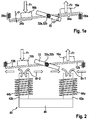
- FIG. 2 schematically depicts a second embodiment of the micromechanical constituent.
- the micromechanical constituent of FIG. 2 encompasses the components, already described above, of the preceding embodiment.
- permanent magnets 16 a and 16 b (all) have a common polarity perpendicular to first rotation axis 20 (and perpendicular to second rotation axis 28 ).
- Electromagnet 40 used as a magnetic device. Electromagnet 40 encompasses two coils 44 a and 44 b each wound around a magnet core 42 a and 42 b . Magnetic field 18 can be generated at permanent magnets 16 a and 16 b by counter-phase energization of the two coils 44 a and 44 b with a harmonically oscillating current signal. Magnetic field 18 producible by way of electromagnet 40 can have radial magnetic field components Br- 1 to Br- 4 , for example, at the at least one first permanent magnet 16 a and at the at least one second permanent magnet 16 b , with the result that the advantageous “seesaw” motions of permanent magnets 16 a and 16 b can be produced.
- Magnetic field 18 generated by way of the electromagnets can also be described as “fountain-shaped” at those end surfaces of magnet cores 42 a and 42 b , which are oriented toward permanent magnets 16 a and 16 b .
- magnetic field components Br- 1 oriented radially with respect to the at least one first permanent magnet 16 a are oriented oppositely to magnetic field components Br- 2 oriented radially with respect to the at least one second permanent magnet 16 b .
- Displaceable element 10 is thereby displaceable with reference to mount 14 around second rotation axis 28 .
- the harmonically oscillating current signal used to energize electromagnet 40 fluctuates at the resonant frequency (of second displacement motion 28 a of displaceable element 10 around second rotation axis 28 )
- the “seesaw” motion of permanent magnets 16 a and 16 b contributes to reliable excitation of the harmonic oscillation of displaceable element 10 around second rotation axis 28 .
- Magnet cores 42 a and 42 b of electromagnet 40 can be connected to each other via a yoke 46 .
- Field lines of magnetic field 18 along a circular path extending partly through yoke 46 can be intensified by way of the yoke.
- FIG. 3 schematically depicts a third example embodiment of the micromechanical constituent.
- electromagnet 50 encompasses only one coil 54 wound around a magnet core 52 .
- a magnetic device of this kind it is possible to produce a strong magnetic field on a side of permanent magnets 16 a and 16 b , or of displaceable element 10 , oriented toward the coil, and an appreciably weaker magnetic field on a side of permanent magnets 16 a and 16 b , or of displaceable element 10 , directed away from coil 54 .
- magnetic field 18 producible by way of the magnetic device has, both at the at least one first permanent magnet 16 a and at the at least one second permanent magnet 16 b , a field strength gradient oriented perpendicularly to first rotation axis 20 (and perpendicularly to second rotation axis 28 ).
- This inhomogeneity of magnetic field 18 can also produce the oppositely directed forces Fr.
- permanent magnets 16 a and 16 b have different polarities, the field of a (large) coil 54 already produces the oppositely directed forces Fr on permanent magnets 16 a and 16 b.
- the at least one first permanent magnet 16 a of the micromechanical constituent of FIG. 3 has a first polarity 56 a oriented perpendicularly to first rotation axis 20 (and perpendicularly to second rotation axis 28 ), while the at least one second permanent magnet 16 b has a second polarity 56 b directly oppositely to first polarity 56 a .
- Displaceable element 10 is thereby displaceable around second rotation axis 28 with reference to mount 14 .
- a harmonically oscillating current signal having the resonant frequency (of second displacement motion 28 a of displaceable element 10 around second rotation axis 28 ) can also be used to energize coil 54 , with the result that the “seesaw” motion of permanent magnets 16 a and 16 b results in reliable excitation of the harmonic oscillation of displaceable element 10 around second rotation axis 28 .
- magnetic field 18 producible by way of the magnetic device can also have, at the at least one first permanent magnet 16 a and at the at least one second permanent magnet 16 b , magnetic field component Bs oriented perpendicularly to first rotation axis 20 , with which the advantageous rotational motions of permanent magnets 16 a and 16 b around first rotation axis 20 can be produced.
- FIG. 4 is a flowchart that illustrates an example method for displacing a displaceable element according to an example embodiment of the present invention.
- the described method can be executed, for example, by way of the micromechanical constituents explained above. Utilization of such a micromechanical constituent is not, however, a prerequisite for implementability of the method.
- the method can instead be carried out using a plurality of displaceable elements that are each suspended on a mount at least by way of a first spring element and a second spring element.
- a magnetic field is generated respectively at at least one first permanent magnet disposed on the first spring element and at least one second permanent magnet disposed on the second spring element, in such a way that because of a magnetic interaction with the magnetic field, a first rotational motion around a first rotation axis is imparted to the first permanent magnet, and a second rotational motion around the first rotation axis is imparted to the at least second permanent magnet.
- a first displacement motion of the displaceable element around the first rotation axis is thereby produced.
- a method step S 2 is also executed simultaneously with method step S 1 .
- method step S 2 by generation of the magnetic field respectively at the at least one first permanent magnet and at the at least one second permanent magnet, additionally the at least one first permanent magnet is excited (because of the magnetic interaction with the magnetic field) to perform a first translational motion tiltedly with respect to the first rotation axis and tiltedly with respect to a second rotation axis oriented tiltedly with respect to the first rotation axis, and the at least one second permanent magnet is excited (because of the magnetic interaction with the magnetic field) to perform a second translational motion directed oppositely to the first translational motion.
- a second displacement motion of the displaceable element around the second rotation axis is thereby produced.
- the magnetic field can be generated respectively at the at least one first permanent magnet and at the at least one second permanent magnet in such a way that (because of the magnetic interaction with the magnetic field) the at least one first permanent magnet is excited to perform the first translational motion at a frequency equal to a resonant frequency of the second displacement motion of the displaceable element around the second rotation axis, and the at least one second permanent magnet is excited to perform the second translational motion at the resonant frequency.
- a harmonic oscillation of the displaceable element around the second rotation axis at the resonant frequency is thus produced as the second displacement motion of the displaceable element.
Abstract
Description
M=I*B*1*b (Eq. 1)
where l is a length of the at least one first or second
F r =U*I*B r (Eq. 2)
2πf=√(k/T) (Eq. 3)
where k is a torsional spring stiffness of the at least one
where Tv is a moment of inertia of
Claims (11)
Applications Claiming Priority (4)
| Application Number | Priority Date | Filing Date | Title |
|---|---|---|---|
| DE102015222305 | 2015-11-12 | ||
| DE102015222305.1A DE102015222305A1 (en) | 2015-11-12 | 2015-11-12 | Micromechanical component and method for adjusting an adjustable element |
| DE102015222305.1 | 2015-11-12 | ||
| PCT/EP2016/075008 WO2017080762A1 (en) | 2015-11-12 | 2016-10-19 | Micromechanical component and method for adjusting an adjustable element |
Publications (2)
| Publication Number | Publication Date |
|---|---|
| US20180314056A1 US20180314056A1 (en) | 2018-11-01 |
| US10627617B2 true US10627617B2 (en) | 2020-04-21 |
Family
ID=57153471
Family Applications (1)
| Application Number | Title | Priority Date | Filing Date |
|---|---|---|---|
| US15/770,085 Active 2036-12-22 US10627617B2 (en) | 2015-11-12 | 2016-10-19 | Micromechanical constituent and method for adjusting an adjustable element |
Country Status (5)
| Country | Link |
|---|---|
| US (1) | US10627617B2 (en) |
| JP (1) | JP2019500638A (en) |
| CN (1) | CN108351509A (en) |
| DE (1) | DE102015222305A1 (en) |
| WO (1) | WO2017080762A1 (en) |
Families Citing this family (4)
| Publication number | Priority date | Publication date | Assignee | Title |
|---|---|---|---|---|
| KR20210040047A (en) * | 2018-08-10 | 2021-04-12 | 하마마츠 포토닉스 가부시키가이샤 | Actuator device and manufacturing method of actuator device |
| KR102254538B1 (en) * | 2019-11-21 | 2021-05-21 | 이화여자대학교 산학협력단 | Optical scanning apparatus |
| JP2021149007A (en) * | 2020-03-19 | 2021-09-27 | 株式会社リコー | Light reflection element, light deflector, image projection device, optical writing device, object recognition device, movable body, and head-mounted display |
| CN113655612B (en) * | 2021-09-03 | 2023-07-25 | 上海科技大学 | High-stability two-dimensional posture adjusting mechanism |
Citations (13)
| Publication number | Priority date | Publication date | Assignee | Title |
|---|---|---|---|---|
| US20030210323A1 (en) | 2002-05-07 | 2003-11-13 | Turner Arthur Monroe | Dynamic laser printer scanning alignment using a torsional hinge mirror |
| US20040007069A1 (en) | 2002-07-08 | 2004-01-15 | Turner Arthur Monroe | Resonant pivoting surface with inertially coupled activation |
| US20040130766A1 (en) | 2002-11-08 | 2004-07-08 | Dewa Andrew Steven | Multilayered oscillating functional surface |
| CN1532582A (en) | 2003-03-11 | 2004-09-29 | 德克萨斯仪器股份有限公司 | Two-way laser printing using single shaft scanning lens |
| US20050078345A1 (en) | 2003-10-09 | 2005-04-14 | Turner Arthur Monroe | Scanning device with improved magnetic drive |
| JP2007322506A (en) | 2006-05-30 | 2007-12-13 | Canon Inc | Optical deflector and optical equipment using the same |
| JP2009020367A (en) | 2007-07-13 | 2009-01-29 | Canon Inc | Oscillating-body device and optical deflector using the same |
| JP2010107666A (en) | 2008-10-29 | 2010-05-13 | Osaka Univ | Optical scanner |
| WO2012070610A1 (en) | 2010-11-24 | 2012-05-31 | 日本電気株式会社 | Optical scanning device |
| US8508098B2 (en) | 2006-12-03 | 2013-08-13 | Maradin Technologies Ltd. | Gimbaled scanning micro-mirror actuation scheme and architecture |
| JP2013190724A (en) | 2012-03-15 | 2013-09-26 | Seiko Epson Corp | Optical scanner and image forming device |
| US20150260847A1 (en) | 2012-07-26 | 2015-09-17 | Apple Inc. | Dual-axis scanning mirror |
| JP2016033593A (en) | 2014-07-31 | 2016-03-10 | 船井電機株式会社 | Scanner device |
Family Cites Families (3)
| Publication number | Priority date | Publication date | Assignee | Title |
|---|---|---|---|---|
| US7446911B2 (en) * | 2002-11-26 | 2008-11-04 | Brother Kogyo Kabushiki Kaisha | Optical scanning apparatus and image forming apparatus |
| JP4277921B2 (en) * | 2007-06-05 | 2009-06-10 | セイコーエプソン株式会社 | Actuator, optical scanner and image forming apparatus |
| DE102008041178B4 (en) * | 2008-08-12 | 2018-11-15 | Robert Bosch Gmbh | Manufacturing method for a micromechanical component |
-
2015
- 2015-11-12 DE DE102015222305.1A patent/DE102015222305A1/en active Pending
-
2016
- 2016-10-19 US US15/770,085 patent/US10627617B2/en active Active
- 2016-10-19 WO PCT/EP2016/075008 patent/WO2017080762A1/en active Application Filing
- 2016-10-19 CN CN201680066341.6A patent/CN108351509A/en active Pending
- 2016-10-19 JP JP2018524340A patent/JP2019500638A/en active Pending
Patent Citations (14)
| Publication number | Priority date | Publication date | Assignee | Title |
|---|---|---|---|---|
| US20030210323A1 (en) | 2002-05-07 | 2003-11-13 | Turner Arthur Monroe | Dynamic laser printer scanning alignment using a torsional hinge mirror |
| US20040007069A1 (en) | 2002-07-08 | 2004-01-15 | Turner Arthur Monroe | Resonant pivoting surface with inertially coupled activation |
| US20040130766A1 (en) | 2002-11-08 | 2004-07-08 | Dewa Andrew Steven | Multilayered oscillating functional surface |
| US6999215B2 (en) * | 2002-11-08 | 2006-02-14 | Texas Instruments Incorporated | Multilayered oscillating functional surface |
| CN1532582A (en) | 2003-03-11 | 2004-09-29 | 德克萨斯仪器股份有限公司 | Two-way laser printing using single shaft scanning lens |
| US20050078345A1 (en) | 2003-10-09 | 2005-04-14 | Turner Arthur Monroe | Scanning device with improved magnetic drive |
| JP2007322506A (en) | 2006-05-30 | 2007-12-13 | Canon Inc | Optical deflector and optical equipment using the same |
| US8508098B2 (en) | 2006-12-03 | 2013-08-13 | Maradin Technologies Ltd. | Gimbaled scanning micro-mirror actuation scheme and architecture |
| JP2009020367A (en) | 2007-07-13 | 2009-01-29 | Canon Inc | Oscillating-body device and optical deflector using the same |
| JP2010107666A (en) | 2008-10-29 | 2010-05-13 | Osaka Univ | Optical scanner |
| WO2012070610A1 (en) | 2010-11-24 | 2012-05-31 | 日本電気株式会社 | Optical scanning device |
| JP2013190724A (en) | 2012-03-15 | 2013-09-26 | Seiko Epson Corp | Optical scanner and image forming device |
| US20150260847A1 (en) | 2012-07-26 | 2015-09-17 | Apple Inc. | Dual-axis scanning mirror |
| JP2016033593A (en) | 2014-07-31 | 2016-03-10 | 船井電機株式会社 | Scanner device |
Non-Patent Citations (1)
| Title |
|---|
| International Search Report dated Dec. 16, 2016 of the corresponding International Application PCT/EP2016/075008 filed Oct. 19, 2016. |
Also Published As
| Publication number | Publication date |
|---|---|
| JP2019500638A (en) | 2019-01-10 |
| DE102015222305A1 (en) | 2017-05-18 |
| WO2017080762A1 (en) | 2017-05-18 |
| CN108351509A (en) | 2018-07-31 |
| US20180314056A1 (en) | 2018-11-01 |
Similar Documents
| Publication | Publication Date | Title |
|---|---|---|
| US10627617B2 (en) | Micromechanical constituent and method for adjusting an adjustable element | |
| JP4827993B2 (en) | Drive device | |
| JP5391579B2 (en) | Vibration element | |
| JP4426969B2 (en) | Small electric appliance with drive mechanism for generating oscillating motion | |
| WO2012172652A1 (en) | Drive device | |
| JP2017167254A (en) | Drive device and mirror device | |
| JP2004194499A (en) | Actuator | |
| JP2016033593A (en) | Scanner device | |
| JP2019015934A (en) | Driving device | |
| JP6812575B2 (en) | Micromechanical parts with oscillators, manufacturing methods for micromechanical parts, and methods for inducing motion of displaceable parts around the axis of rotation | |
| JP4958195B2 (en) | Drive device | |
| JP2008058434A (en) | Rocking apparatus, light deflector using rocking apparatus, and image forming apparatus using light deflector | |
| JP4958196B2 (en) | Drive device | |
| JP4896270B1 (en) | Drive device | |
| JP7044498B2 (en) | Actuator | |
| JP6914124B2 (en) | Drive device | |
| JP5624213B2 (en) | Drive device | |
| JP6785588B2 (en) | Drive device | |
| JP2018013783A (en) | Mechanical component and method for adjusting adjustable part around at least rotational axis | |
| JP6182258B2 (en) | Vibration generator | |
| WO2012172653A1 (en) | Drive device | |
| US11340446B2 (en) | Actuator | |
| JP7386671B2 (en) | Drive device and drive method | |
| JP6929006B2 (en) | Drive device | |
| JP2631785B2 (en) | Vibration type actuator |
Legal Events
| Date | Code | Title | Description |
|---|---|---|---|
| FEPP | Fee payment procedure |
Free format text: ENTITY STATUS SET TO UNDISCOUNTED (ORIGINAL EVENT CODE: BIG.); ENTITY STATUS OF PATENT OWNER: LARGE ENTITY |
|
| AS | Assignment |
Owner name: ROBERT BOSCH GMBH, GERMANY Free format text: ASSIGNMENT OF ASSIGNORS INTEREST;ASSIGNORS:SCHATZ, FRANK;MUCHOW, JOERG;HATTASS, MIRKO;AND OTHERS;SIGNING DATES FROM 20180515 TO 20180621;REEL/FRAME:046223/0697 |
|
| STPP | Information on status: patent application and granting procedure in general |
Free format text: DOCKETED NEW CASE - READY FOR EXAMINATION |
|
| STPP | Information on status: patent application and granting procedure in general |
Free format text: NON FINAL ACTION MAILED |
|
| STPP | Information on status: patent application and granting procedure in general |
Free format text: RESPONSE TO NON-FINAL OFFICE ACTION ENTERED AND FORWARDED TO EXAMINER |
|
| STPP | Information on status: patent application and granting procedure in general |
Free format text: NOTICE OF ALLOWANCE MAILED -- APPLICATION RECEIVED IN OFFICE OF PUBLICATIONS |
|
| STCF | Information on status: patent grant |
Free format text: PATENTED CASE |
|
| MAFP | Maintenance fee payment |
Free format text: PAYMENT OF MAINTENANCE FEE, 4TH YEAR, LARGE ENTITY (ORIGINAL EVENT CODE: M1551); ENTITY STATUS OF PATENT OWNER: LARGE ENTITY Year of fee payment: 4 |