US10623964B2 - Wireless communication method and wireless communication terminal for spatial reuse of overlapped basic service set - Google Patents
Wireless communication method and wireless communication terminal for spatial reuse of overlapped basic service set Download PDFInfo
- Publication number
- US10623964B2 US10623964B2 US16/141,973 US201816141973A US10623964B2 US 10623964 B2 US10623964 B2 US 10623964B2 US 201816141973 A US201816141973 A US 201816141973A US 10623964 B2 US10623964 B2 US 10623964B2
- Authority
- US
- United States
- Prior art keywords
- spatial reuse
- ppdu
- trigger
- field
- terminal
- Prior art date
- Legal status (The legal status is an assumption and is not a legal conclusion. Google has not performed a legal analysis and makes no representation as to the accuracy of the status listed.)
- Active
Links
Images


Classifications
-
- H—ELECTRICITY
- H04—ELECTRIC COMMUNICATION TECHNIQUE
- H04W—WIRELESS COMMUNICATION NETWORKS
- H04W16/00—Network planning, e.g. coverage or traffic planning tools; Network deployment, e.g. resource partitioning or cells structures
- H04W16/02—Resource partitioning among network components, e.g. reuse partitioning
- H04W16/10—Dynamic resource partitioning
-
- H—ELECTRICITY
- H04—ELECTRIC COMMUNICATION TECHNIQUE
- H04W—WIRELESS COMMUNICATION NETWORKS
- H04W28/00—Network traffic management; Network resource management
- H04W28/16—Central resource management; Negotiation of resources or communication parameters, e.g. negotiating bandwidth or QoS [Quality of Service]
- H04W28/18—Negotiating wireless communication parameters
- H04W28/20—Negotiating bandwidth
-
- H—ELECTRICITY
- H04—ELECTRIC COMMUNICATION TECHNIQUE
- H04W—WIRELESS COMMUNICATION NETWORKS
- H04W52/00—Power management, e.g. TPC [Transmission Power Control], power saving or power classes
- H04W52/04—TPC
- H04W52/06—TPC algorithms
- H04W52/14—Separate analysis of uplink or downlink
- H04W52/146—Uplink power control
-
- H—ELECTRICITY
- H04—ELECTRIC COMMUNICATION TECHNIQUE
- H04W—WIRELESS COMMUNICATION NETWORKS
- H04W52/00—Power management, e.g. TPC [Transmission Power Control], power saving or power classes
- H04W52/04—TPC
- H04W52/30—TPC using constraints in the total amount of available transmission power
- H04W52/34—TPC management, i.e. sharing limited amount of power among users or channels or data types, e.g. cell loading
-
- H—ELECTRICITY
- H04—ELECTRIC COMMUNICATION TECHNIQUE
- H04W—WIRELESS COMMUNICATION NETWORKS
- H04W74/00—Wireless channel access, e.g. scheduled or random access
- H04W74/002—Transmission of channel access control information
-
- H—ELECTRICITY
- H04—ELECTRIC COMMUNICATION TECHNIQUE
- H04W—WIRELESS COMMUNICATION NETWORKS
- H04W74/00—Wireless channel access, e.g. scheduled or random access
- H04W74/08—Non-scheduled or contention based access, e.g. random access, ALOHA, CSMA [Carrier Sense Multiple Access]
- H04W74/0808—Non-scheduled or contention based access, e.g. random access, ALOHA, CSMA [Carrier Sense Multiple Access] using carrier sensing, e.g. as in CSMA
-
- H—ELECTRICITY
- H04—ELECTRIC COMMUNICATION TECHNIQUE
- H04W—WIRELESS COMMUNICATION NETWORKS
- H04W76/00—Connection management
- H04W76/10—Connection setup
- H04W76/11—Allocation or use of connection identifiers
-
- H—ELECTRICITY
- H04—ELECTRIC COMMUNICATION TECHNIQUE
- H04W—WIRELESS COMMUNICATION NETWORKS
- H04W24/00—Supervisory, monitoring or testing arrangements
- H04W24/08—Testing, supervising or monitoring using real traffic
-
- H—ELECTRICITY
- H04—ELECTRIC COMMUNICATION TECHNIQUE
- H04W—WIRELESS COMMUNICATION NETWORKS
- H04W52/00—Power management, e.g. TPC [Transmission Power Control], power saving or power classes
- H04W52/04—TPC
- H04W52/18—TPC being performed according to specific parameters
- H04W52/24—TPC being performed according to specific parameters using SIR [Signal to Interference Ratio] or other wireless path parameters
- H04W52/245—TPC being performed according to specific parameters using SIR [Signal to Interference Ratio] or other wireless path parameters taking into account received signal strength
-
- H—ELECTRICITY
- H04—ELECTRIC COMMUNICATION TECHNIQUE
- H04W—WIRELESS COMMUNICATION NETWORKS
- H04W72/00—Local resource management
- H04W72/04—Wireless resource allocation
- H04W72/044—Wireless resource allocation based on the type of the allocated resource
- H04W72/046—Wireless resource allocation based on the type of the allocated resource the resource being in the space domain, e.g. beams
-
- H—ELECTRICITY
- H04—ELECTRIC COMMUNICATION TECHNIQUE
- H04W—WIRELESS COMMUNICATION NETWORKS
- H04W84/00—Network topologies
- H04W84/02—Hierarchically pre-organised networks, e.g. paging networks, cellular networks, WLAN [Wireless Local Area Network] or WLL [Wireless Local Loop]
- H04W84/10—Small scale networks; Flat hierarchical networks
- H04W84/12—WLAN [Wireless Local Area Networks]
-
- H—ELECTRICITY
- H04—ELECTRIC COMMUNICATION TECHNIQUE
- H04W—WIRELESS COMMUNICATION NETWORKS
- H04W88/00—Devices specially adapted for wireless communication networks, e.g. terminals, base stations or access point devices
- H04W88/02—Terminal devices
Definitions
- the present invention relates to a wireless communication method and a wireless communication terminal for a spatial reuse operation of an overlapping basic service set, and more particularly, to a wireless communication method and a wireless communication terminal for supporting a spatial reuse operation of an overlapping basic service set to efficiently use a wireless resource.
- the wireless LAN technology allows mobile apparatuses including a smart phone, a smart pad, a laptop computer, a portable multimedia player, an embedded apparatus, and the like to wirelessly access the Internet in home or a company or a specific service providing area based on a wireless communication technology in a short range.
- IEEE 802.11 has commercialized or developed various technological standards since an initial wireless LAN technology is supported using frequencies of 2.4 GHz.
- the IEEE 802.11b supports a communication speed of a maximum of 11 Mbps while using frequencies of a 2.4 GHz band.
- IEEE 802.11a which is commercialized after the IEEE 802.11b uses frequencies of not the 2.4 GHz band but a 5 GHz band to reduce an influence by interference as compared with the frequencies of the 2.4 GHz band which are significantly congested and improves the communication speed up to a maximum of 54 Mbps by using an OFDM technology.
- the IEEE 802.11a has a disadvantage in that a communication distance is shorter than the IEEE 802.11b.
- IEEE 802.11g uses the frequencies of the 2.4 GHz band similarly to the IEEE 802.11b to implement the communication speed of a maximum of 54 Mbps and satisfies backward compatibility to significantly come into the spotlight and further, is superior to the IEEE 802.11a in terms of the communication distance.
- IEEE 802.11n As a technology standard established to overcome a limitation of the communication speed which is pointed out as a weak point in a wireless LAN, IEEE 802.11n has been provided.
- the IEEE 802.11n aims at increasing the speed and reliability of a network and extending an operating distance of a wireless network.
- the IEEE 802.11n supports a high throughput (HT) in which a data processing speed is a maximum of 540 Mbps or more and further, is based on a multiple inputs and multiple outputs (MIMO) technology in which multiple antennas are used at both sides of a transmitting unit and a receiving unit in order to minimize a transmission error and optimize a data speed.
- MIMO multiple inputs and multiple outputs
- the standard can use a coding scheme that transmits multiple copies which overlap with each other in order to increase data reliability.
- IEEE 802.11ac supports a wide bandwidth (80 to 160 MHz) in the 5 GHz frequencies.
- the IEEE 802.11ac standard is defined only in the 5 GHz band, but initial 11ac chipsets will support even operations in the 2.4 GHz band for the backward compatibility with the existing 2.4 GHz band products.
- wireless LAN speeds of multiple stations are enabled up to a minimum of 1 Gbps and a maximum single link speed is enabled up to a minimum of 500 Mbps.
- This is achieved by extending concepts of a wireless interface accepted by 802.11n, such as a wider wireless frequency bandwidth (a maximum of 160 MHz), more MIMO spatial streams (a maximum of 8), multi-user MIMO, and high-density modulation (a maximum of 256 QAM).
- IEEE 802.11ad has been provided as a scheme that transmits data by using a 60 GHz band instead of the existing 2.4 GHz/5 GHz.
- the IEEE 802.11ad is a transmission standard that provides a speed of a maximum of 7 Gbps by using a beamforming technology and is suitable for high bit rate moving picture streaming such as massive data or non-compression HD video.
- the 60 GHz frequency band can be used only among devices in a short-distance space.
- next-generation wireless LAN standards after the 802.11ac and 802.11ad, discussion for providing a high-efficiency and high-performance wireless LAN communication technology in a high-density environment is continuously performed. That is, in a next-generation wireless LAN environment, communication having high frequency efficiency needs to be provided indoors/outdoors under the presence of high-density stations and access points (APs) and various technologies for implementing the communication are required.
- APs access points
- the present invention has an object to provide high-efficiency/high-performance wireless LAN communication in a high-density environment as described above.
- the present invention has an object to solve an ambiguity of a spatial reuse field identification of an inter-BSS (or an overlapping BSS) terminal receiving a trigger-based PPDU.
- the present invention has an object to provide a wireless communication method and a wireless communication terminal in a high density environment including an overlapping basic service set.
- the present invention provides a wireless communication method and a wireless communication terminal as below.
- an exemplary embodiment of the present invention provides a wireless communication terminal, the terminal including: a processor; and a communication unit, wherein the processor receives a trigger frame indicating an uplink multi-user transmission, and transmits a trigger-based PHY protocol data unit (PPDU) in response to the received trigger frame, wherein the trigger-based PPDU comprises a spatial reuse parameter for spatial reuse operation of an overlapping basic service set (OBSS) terminal.
- a wireless communication terminal including: a processor; and a communication unit, wherein the processor receives a trigger frame indicating an uplink multi-user transmission, and transmits a trigger-based PHY protocol data unit (PPDU) in response to the received trigger frame, wherein the trigger-based PPDU comprises a spatial reuse parameter for spatial reuse operation of an overlapping basic service set (OBSS) terminal.
- OBSS overlapping basic service set
- an exemplary embodiment of the present invention provides a wireless communication method of a wireless communication terminal, including: receiving a trigger frame indicating an uplink multi-user transmission; and transmitting a trigger-based PHY protocol data unit (PPDU) in response to the received trigger frame; wherein the trigger-based PPDU comprises a spatial reuse parameter for spatial reuse operation of an overlapping basic service set (OBSS) terminal.
- a trigger-based PHY protocol data unit PPDU
- OBSS overlapping basic service set
- a spatial reuse parameter for the first frequency band and a spatial reuse parameter for the second frequency band may be set to the same value.
- a high efficiency signal field A (HE-SIG-A) of the trigger-based PPDU may contain a plurality of spatial reuse fields, and the plurality of spatial reuse fields may carry spatial reuse parameters obtained from the trigger frame, and each of the plurality of spatial reuse fields may indicate a spatial reuse parameter for an individual subband constituting the total bandwidth on which the transmission of the trigger-based PPDU is performed.
- HE-SIG-A high efficiency signal field A
- the plurality of spatial reuse fields may comprise a first spatial reuse field, a second spatial reuse field, a third spatial reuse field, and a fourth spatial reuse field, and when the total bandwidth on which the transmission of the trigger-based PPDU is performed is a non-contiguous first frequency band and second frequency band, the first spatial reuse field and the second spatial reuse field for the first frequency band may be respectively set to the same value as the third spatial reuse field and the fourth spatial reuse field for the second frequency band.
- the spatial reuse field may indicate a spatial reuse parameter for a subband of a first frequency bandwidth, and when the total bandwidth on which the transmission of the trigger-based PPDU is performed exceeds the predetermined bandwidth, the spatial reuse field may indicate a spatial reuse parameter for a subband of a second frequency bandwidth which is wider than the first frequency bandwidth.
- the spatial reuse parameter may be set based on a transmission power of a PPDU containing the trigger frame and an acceptable interference level of a base wireless communication terminal that transmitted the PPDU containing the trigger frame.
- the spatial reuse operation of the OBSS terminal may comprise an operation of adjusting a transmission power of the OBSS terminal based on the spatial reuse parameter.
- the operation of adjusting the transmission power may be performed based on a received signal strength of a PPDU containing the trigger frame measured by the OBSS terminal and a spatial reuse parameter obtained by the OBSS terminal.
- the transmission power of the OBSS terminal may be set to be lower than a value obtained by subtracting the measured received signal strength from the obtained spatial reuse parameter value.
- the OBSS terminal may obtain the spatial reuse parameter from at least one of the trigger frame and the trigger-based PPDU.
- the ambiguity of the spatial reuse field identification of an inter-BSS (or an overlapping BSS) terminal receiving a trigger-based PPDU can be solved.
- the spatial reuse operation can be performed, thereby efficiently using the wireless resources.
- FIG. 1 illustrates a wireless LAN system according to an embodiment of the present invention.
- FIG. 2 illustrates a wireless LAN system according to another embodiment of the present invention.
- FIG. 3 illustrates a configuration of a station according to an embodiment of the present invention.
- FIG. 4 illustrates a configuration of an access point according to an embodiment of the present invention.
- FIG. 5 schematically illustrates a process in which a STA and an AP set a link.
- FIG. 6 illustrates a carrier sense multiple access (CSMA)/collision avoidance (CA) method used in wireless LAN communication.
- CSMA carrier sense multiple access
- CA collision avoidance
- FIG. 7 illustrates a channel access method using a spatial reuse operation according to an embodiment of the present invention.
- FIG. 8 illustrates an SR operation of a terminal according to the embodiment of the present invention when a PPDU containing a trigger frame is transmitted in an OBSS.
- FIG. 9 illustrates an SR operation of a terminal according to the embodiment of the present invention in more detail when a PPDU containing a trigger frame is transmitted in an OBSS.
- FIG. 10 illustrates the embodiment in which a terminal performs an SR operation based on a contention procedure when a PPDU containing a trigger frame is transmitted in an OBSS.
- FIG. 11 illustrates an embodiment of an operation in which a terminal sets a NAV when a PPDU containing a trigger frame is transmitted in an OBSS.
- FIG. 12 illustrates the embodiment of transmitting a spatial reuse parameter via a trigger frame and a corresponding trigger-based PPDU.
- FIG. 13 illustrates a method for signaling spatial reuse fields of a trigger-based PPDU according to the embodiment of the present invention.
- FIG. 14 illustrates an embodiment of a method for setting spatial reuse fields of a trigger-based PPDU.
- FIGS. 15 to 19 illustrate methods for configuring an HE-SIG-A and spatial reuse fields according to the embodiment of the present invention.
- FIG. 20 illustrates another embodiment of a method for setting spatial reuse fields of a trigger-based PPDU.
- FIG. 21 illustrates yet another embodiment of a method for setting and using spatial reuse fields of a trigger-based PPDU.
- FIG. 22 illustrates a method for configuring an HE-SIG-A and spatial reuse fields of a trigger-based PPDU according to a further embodiment of the present invention.
- FIG. 23 illustrates a method for signaling spatial reuse fields of a trigger-based PPDU according to another embodiment of the present invention.
- FIG. 24 illustrates a method for signaling a bandwidth field according to an embodiment of the present invention.
- FIG. 1 is a diagram illustrating a wireless LAN system according to an embodiment of the present invention.
- the wireless LAN system includes one or more basic service sets (BSS) and the BSS represents a set of apparatuses which are successfully synchronized with each other to communicate with each other.
- BSS basic service sets
- the BSS may be classified into an infrastructure BSS and an independent BSS (IBSS) and FIG. 1 illustrates the infrastructure BSS between them.
- IBSS independent BSS
- the infrastructure BSS (BSS 1 and BSS 2 ) includes one or more stations STA 1 , STA 2 , STA 3 , STA 4 , and STA 5 , access points PCP/AP- 1 and PCP/AP- 2 which are stations providing a distribution service, and a distribution system (DS) connecting the multiple access points PCP/AP- 1 and PCP/AP- 2 .
- BSS 1 and BSS 2 includes one or more stations STA 1 , STA 2 , STA 3 , STA 4 , and STA 5 , access points PCP/AP- 1 and PCP/AP- 2 which are stations providing a distribution service, and a distribution system (DS) connecting the multiple access points PCP/AP- 1 and PCP/AP- 2 .
- DS distribution system
- the station is a predetermined device including medium access control (MAC) following a regulation of an IEEE 802.11 standard and a physical layer interface for a wireless medium, and includes both a non-access point (non-AP) station and an access point (AP) in a broad sense.
- MAC medium access control
- a term ‘terminal’ may be used to refer to a non-AP STA, or an AP, or to both terms.
- a station for wireless communication includes a processor and a communication unit and according to the embodiment, may further include a user interface unit and a display unit.
- the processor may generate a frame to be transmitted through a wireless network or process a frame received through the wireless network and besides, perform various processing for controlling the station.
- the communication unit is functionally connected with the processor and transmits and receives frames through the wireless network for the station.
- a terminal may be used as a term which includes user equipment (UE).
- the access point is an entity that provides access to the distribution system (DS) via wireless medium for the station associated therewith.
- DS distribution system
- the AP is used as a concept including a personal BSS coordination point (PCP) and may include concepts including a centralized controller, a base station (BS), a node-B, a base transceiver system (BTS), and a site controller in a broad sense.
- PCP personal BSS coordination point
- BS base station
- node-B a node-B
- BTS base transceiver system
- site controller in a broad sense.
- an AP may also be referred to as a base wireless communication terminal.
- the base wireless communication terminal may be used as a term which includes an AP, a base station, an eNB (i.e. eNodeB) and a transmission point (TP) in a broad sense.
- the base wireless communication terminal may include various types of wireless communication terminals that allocate medium resources and perform scheduling in communication with a plurality of wireless communication terminals.
- a plurality of infrastructure BSSs may be connected with each other through the distribution system (DS).
- DS distribution system
- ESS extended service set
- FIG. 2 illustrates an independent BSS which is a wireless LAN system according to another embodiment of the present invention.
- FIG. 2 duplicative description of parts, which are the same as or correspond to the embodiment of FIG. 1 , will be omitted.
- a BSS 3 illustrated in FIG. 2 is the independent BSS and does not include the AP, all stations STA 6 and STA 7 are not connected with the AP.
- the independent BSS is not permitted to access the distribution system and forms a self-contained network.
- the respective stations STA 6 and STA 7 may be directly connected with each other.
- FIG. 3 is a block diagram illustrating a configuration of a station 100 according to an embodiment of the present invention.
- the station 100 may include a processor 110 , a communication unit 120 , a user interface unit 140 , a display unit 150 , and a memory 160 .
- the communication unit 120 transmits and receives a wireless signal such as a wireless LAN packet, or the like and may be embedded in the station 100 or provided as an exterior.
- the communication unit 120 may include at least one communication module using different frequency bands.
- the communication unit 120 may include communication modules having different frequency bands such as 2.4 GHz, 5 GHz, and 60 GHz.
- the station 100 may include a communication module using a frequency band of 6 GHz or more and a communication module using a frequency band of 6 GHz or less.
- the respective communication modules may perform wireless communication with the AP or an external station according to a wireless LAN standard of a frequency band supported by the corresponding communication module.
- the communication unit 120 may operate only one communication module at a time or simultaneously operate multiple communication modules together according to the performance and requirements of the station 100 .
- each communication module may be implemented by independent elements or a plurality of modules may be integrated into one chip.
- the communication unit 120 may represent a radio frequency (RF) communication module for processing an RF signal.
- RF radio frequency
- the user interface unit 140 includes various types of input/output means provided in the station 100 . That is, the user interface unit 140 may receive a user input by using various input means and the processor 110 may control the station 100 based on the received user input. Further, the user interface unit 140 may perform output based on a command of the processor 110 by using various output means.
- the display unit 150 outputs an image on a display screen.
- the display unit 150 may output various display objects such as contents executed by the processor 110 or a user interface based on a control command of the processor 110 , and the like.
- the memory 160 stores a control program used in the station 100 and various resulting data.
- the control program may include an access program required for the station 100 to access the AP or the external station.
- the processor 110 of the present invention may execute various commands or programs and process data in the station 100 . Further, the processor 110 may control the respective units of the station 100 and control data transmission/reception among the units. According to the embodiment of the present invention, the processor 110 may execute the program for accessing the AP stored in the memory 160 and receive a communication configuration message transmitted by the AP. Further, the processor 110 may read information on a priority condition of the station 100 included in the communication configuration message and request the access to the AP based on the information on the priority condition of the station 100 .
- the processor 110 of the present invention may represent a main control unit of the station 100 and according to the embodiment, the processor 110 may represent a control unit for individually controlling some component of the station 100 , for example, the communication unit 120 , and the like.
- the processor 110 may be a modem or a modulator/demodulator for modulating and demodulating wireless signals transmitted to and received from the communication unit 120 .
- the processor 110 controls various operations of wireless signal transmission/reception of the station 100 according to the embodiment of the present invention. A detailed embodiment thereof will be described below.
- the station 100 illustrated in FIG. 3 is a block diagram according to an embodiment of the present invention, where separate blocks are illustrated as logically distinguished elements of the device. Accordingly, the elements of the device may be mounted in a single chip or multiple chips depending on design of the device. For example, the processor 110 and the communication unit 120 may be implemented while being integrated into a single chip or implemented as a separate chip. Further, in the embodiment of the present invention, some components of the station 100 , for example, the user interface unit 140 and the display unit 150 may be optionally provided in the station 100 .
- FIG. 4 is a block diagram illustrating a configuration of an AP 200 according to an embodiment of the present invention.
- the AP 200 may include a processor 210 , a communication unit 220 , and a memory 260 .
- FIG. 4 among the components of the AP 200 , duplicative description of parts which are the same as or correspond to the components of the station 100 of FIG. 2 will be omitted.
- the AP 200 includes the communication unit 220 for operating the BSS in at least one frequency band.
- the communication unit 220 of the AP 200 may also include a plurality of communication modules using different frequency bands. That is, the AP 200 according to the embodiment of the present invention may include two or more communication modules among different frequency bands, for example, 2.4 GHz, 5 GHz, and 60 GHz together.
- the AP 200 may include a communication module using a frequency band of 6 GHz or more and a communication module using a frequency band of 6 GHz or less.
- the respective communication modules may perform wireless communication with the station according to a wireless LAN standard of a frequency band supported by the corresponding communication module.
- the communication unit 220 may operate only one communication module at a time or simultaneously operate multiple communication modules together according to the performance and requirements of the AP 200 .
- the communication unit 220 may represent a radio frequency (RF) communication module for processing an RF signal.
- RF radio frequency
- the memory 260 stores a control program used in the AP 200 and various resulting data.
- the control program may include an access program for managing the access of the station.
- the processor 210 may control the respective units of the AP 200 and control data transmission/reception among the units.
- the processor 210 may execute the program for accessing the station stored in the memory 260 and transmit communication configuration messages for one or more stations.
- the communication configuration messages may include information about access priority conditions of the respective stations.
- the processor 210 performs an access configuration according to an access request of the station.
- the processor 210 may be a modem or a modulator/demodulator for modulating and demodulating wireless signals transmitted to and received from the communication unit 220 .
- the processor 210 controls various operations such as wireless signal transmission/reception of the AP 200 according to the embodiment of the present invention. A detailed embodiment thereof will be described below.
- FIG. 5 is a diagram schematically illustrating a process in which a STA sets a link with an AP.
- the scanning step is a step in which the STA 100 obtains access information of BSS operated by the AP 200 .
- a method for performing the scanning includes a passive scanning method in which the AP 200 obtains information by using a beacon message (S 101 ) which is periodically transmitted and an active scanning method in which the STA 100 transmits a probe request to the AP (S 103 ) and obtains access information by receiving a probe response from the AP (S 105 ).
- the STA 100 that successfully receives wireless access information in the scanning step performs the authentication step by transmitting an authentication request (S 107 a ) and receiving an authentication response from the AP 200 (S 107 b ).
- the STA 100 performs the association step by transmitting an association request (S 109 a ) and receiving an association response from the AP 200 (S 109 b ).
- an association basically means a wireless association, but the present invention is not limited thereto, and the association may include both the wireless association and a wired association in a broad sense.
- the authentication server 300 is a server that processes 802.1X based authentication with the STA 100 and may be present in physical association with the AP 200 or present as a separate server.
- FIG. 6 illustrates a carrier sense multiple access (CSMA)/collision avoidance (CA) method used in wireless LAN communication.
- CSMA carrier sense multiple access
- CA collision avoidance
- a terminal that performs a wireless LAN communication checks whether a channel is busy by performing carrier sensing before transmitting data.
- a wireless signal having a predetermined strength or more is sensed, it is determined that the corresponding channel is busy and the terminal delays the access to the corresponding channel.
- Such a process is referred to as clear channel assessment (CCA) and a level to decide whether the corresponding signal is sensed is referred to as a CCA threshold.
- CCA clear channel assessment
- a wireless signal having the CCA threshold or more which is received by the terminal, indicates the corresponding terminal as a receiver, the terminal processes the received wireless signal. Meanwhile, when a wireless signal is not sensed in the corresponding channel or a wireless signal having a strength smaller than the CCA threshold is sensed, it is determined that the channel is idle.
- each terminal having data to be transmitted performs a backoff procedure after an inter frame space (IFS) time depending on a situation of each terminal, for instance, an arbitration IFS (AIFS), a PCF IFS (PIFS), or the like elapses.
- AIFS may be used as a component which substitutes for the existing DCF IFS (DIFS).
- DIFS DCF IFS
- Each terminal stands by while decreasing slot time(s) as long as a random number determined by the corresponding terminal during an interval of an idle state of the channel and a terminal that completely exhausts the slot time(s) attempts to access the corresponding channel.
- a contention window interval an interval in which each terminal performs the backoff procedure is referred to as a contention window interval.
- the corresponding terminal may transmit data through the channel.
- the terminals which collide with each other are assigned with new random numbers, respectively to perform the backoff procedure again.
- a random number newly assigned to each terminal may be decided within a range (2*CW) which is twice larger than a range (a contention window, CW) of a random number which the corresponding terminal has previously used.
- each terminal attempts the access by performing the backoff procedure again in a next contention window interval and in this case, each terminal performs the backoff procedure from slot time(s) which remained in the previous contention window interval.
- one wireless communication terminal can simultaneously transmit data to a plurality of wireless communication terminals. Further, one wireless communication terminal can simultaneously receive data from a plurality of wireless communication terminals. For example, a downlink multi-user (DL-MU) transmission in which an AP simultaneously transmits data to a plurality of STAs, and an uplink multi-user (UL-MU) transmission in which a plurality of STAs simultaneously transmit data to the AP may be performed.
- DL-MU downlink multi-user
- UL-MU uplink multi-user
- the UL-MU transmission process may be managed by the AP.
- the UL-MU transmission may be performed in response to a trigger frame transmitted by the AP.
- the trigger frame indicates a UL-MU transmission of at least one STA.
- the STAs simultaneously transmit uplink data a predetermined IFS time after receiving the trigger frame.
- the trigger frame may indicate data transmission time point of uplink transmission STAs and may inform channel (or subchannel) information allocated to the uplink transmission STAs.
- the AP When the AP transmits a trigger frame, a plurality of STAs transmit uplink data through each allocated subcarrier at the time specified by the trigger frame. After the uplink data transmission is completed, the AP transmits an ACK to STAs that have successfully transmitted uplink data. In this case, the AP may transmit a predetermined multi-STA block ACK (M-BA) as an ACK for a plurality of STAs.
- M-BA multi-STA block ACK
- the trigger frame may indicate identification information of each STA participating in the UL-MU transmission and information of the allocated resource unit.
- the identification information of the STA includes at least one of an association ID (AID), a partial AID, and a MAC address of the STA.
- the information of the resource unit includes the size and placement information of the resource unit.
- FIG. 7 illustrates a channel access method using a spatial reuse (SR) operation according to an embodiment of the present invention.
- SR spatial reuse
- the terminal may determine whether a frame is an intra-BSS frame or an inter-BSS frame based on information for identifying a BSS of a received frame.
- the information for identifying a BSS includes at least one of a BSS color, a partial BSS color, a partial AID, or a MAC address.
- the non-legacy terminal may refer to a terminal that complies with the next generation wireless LAN standard (i.e., IEEE 802.11ax).
- the intra-BSS frame indicates a frame transmitted from a terminal belonging to the same BSS
- the inter-BSS frame indicates a frame transmitted from a terminal belonging to an overlapping BSS (OBSS) or another BSS.
- OBSS overlapping BSS
- the non-legacy terminal may perform different operations depending on whether the received frame is an intra-BSS frame. That is, when the received frame is determined as an intra-BSS frame, the terminal may perform the first operation. In addition, when the received frame is determined as an inter-BSS frame, the terminal may perform the second operation different from the first operation. According to an embodiment, the second operation performed by the terminal when the received frame is determined as an inter-BSS frame may be the SR operation. According to the embodiment of the present invention, the first operation and the second operation may be set in various ways.
- the terminal may perform channel access based on different thresholds depending on whether the received frame is an intra-BSS frame. More specifically, when the received frame is determined as an intra-BSS frame, the terminal accesses the channel based on the first CCA threshold (i.e., the first operation). That is, the terminal performs a CCA based on the first CCA threshold value, and determines whether the channel is busy based on a result of performing the CCA. On the other hand, when the received frame is determined as an inter-BSS frame, the terminal may access the channel based on the second CCA threshold value (i.e., the second operation, or SR operation), which is distinct from the first CCA threshold value.
- the first CCA threshold i.e., the first operation
- the terminal may access the channel based on the second CCA threshold value (i.e., the second operation, or SR operation), which is distinct from the first CCA threshold value.
- the terminal determines whether the channel is busy based on both the first CCA threshold value and the second CCA threshold value.
- the second CCA threshold value is an OBSS PD level set for determining whether a channel is busy according to a received signal strength of an inter-BSS frame.
- the second CCA threshold value may have a value equal to or larger than the first CCA threshold value.
- the terminal may adjust a transmission power of a PHY protocol data unit (PPDU) transmitted by the terminal according to whether the received frame is an intra-BSS frame. More specifically, when the received frame is determined as an inter-BSS frame, the terminal may adjust the transmission power of the PPDU based on the SR parameter extracted from the received frame (i.e., the second operation, or SR operation). According to an embodiment, the terminal may increase the transmission power based on the SR parameter extracted from the received frame.
- the non-legacy frame may contain an SR field for SR operation of OBSS terminals, and specific embodiments thereof will be described later.
- the terminal does not perform the transmission power adjustment based on the SR parameter.
- the transmitted non-legacy frames 310 and 320 may contain information (i.e., information indicating whether the SR is allowed) indicating whether the SR operation for the corresponding PPDU is allowed.
- the information indicating whether the SR is allowed may be represented through a predetermined index of the SR field. For example, if the value of the SR field is 0 (i.e., if all bit values of the SR field are 0), it may indicate that the SR operation is not allowed.
- information, contained in the received first frame 310 indicating whether the SR is allowed indicates that the SR operation for the corresponding PPDU is allowed.
- information, contained in the received second frame 320 indicates whether the SR is allowed indicates that the SR operation for the corresponding PPDU is not allowed.
- both of the received first frame 310 and the received second frame 320 are inter-BSS frames.
- the terminal receiving the first frame 310 determines whether the received frame 310 is an intra-BSS frame or an inter-BSS frame. In addition, the terminal checks information indicating whether the SR is allowed in the received frame 310 . In this case, the received frame 310 is determined as an inter-BSS frame, and the information indicating whether the SR is allowed indicates that the SR operation for the corresponding PPDU is allowed. Accordingly, the terminal may perform the SR operations according to the above-described embodiments. That is, the terminal may determine whether the channel is busy based on both the first CCA threshold value and the second CCA threshold value. In addition, the terminal may adjust the transmission power based on the SR parameter extracted from the received frame 310 .
- the terminal receiving the second frame 320 determines whether the received frame 320 is an intra-BSS frame or an inter-BSS frame. In addition, the terminal checks information indicating whether the SR is allowed in the received frame 320 . In this case, the received frame 320 is determined as an inter-BSS frame, and the information indicating whether the SR is allowed indicates that the SR operation for the corresponding PPDU is not allowed. Therefore, the terminal does not perform the SR operations according to the above-described embodiment. That is, although the received frame 320 is determined as an inter-BSS frame, the terminal accesses the channel based on the first CCA threshold value. In addition, the terminal does not perform the transmission power adjustment based on the SR parameter extracted from the received frame 320 .
- the information indicating whether the SR is allowed may be transmitted through a frame of the legacy format.
- the AP can protect the transmitted legacy frame from SR operations of the non-legacy terminals.
- the information indicating whether the SR is allowed may be transmitted via an L-preamble.
- reserved bit(s) of an L-SIG of the L-preamble may indicate whether the SR is allowed.
- guard sub-carrier(s) of the L-SIG of the L-preamble may carry the information indicating whether the SR is allowed.
- the information indicating whether the SR is allowed may be transmitted via a VHT-preamble.
- reserved bit(s) of a VHT-SIG-A 1 or VHT-SIG-A 2 of the VHT-preamble may indicate whether the SR is allowed.
- guard subcarrier(s) of the VHT-SIG-A 1 or VHT-SIG-A 2 of the VHT-preamble may carry the information indicating whether the SR is allowed.
- the information indicating whether the SR is allowed may be transmitted via an HT-preamble.
- reserved bit(s) of the HT-preamble may indicate whether the SR is allowed.
- guard sub-carrier(s) of the HT-preamble may carry the information indicating whether the SR is allowed.
- the information indicating whether the SR is allowed may be transmitted via a MAC header.
- FIG. 8 illustrates an SR operation of a terminal according to the embodiment of the present invention when a PPDU containing a trigger frame is transmitted in an OBSS.
- BSS 1 includes STA 1 and STA 2 .
- STA 1 is a non-AP STA and STA 2 is an AP.
- BSS 2 includes STA 3 and STA 4 .
- STA 3 is a non-AP STA and STA 4 is an AP.
- STA 2 transmits a trigger frame (or a PPDU containing a trigger frame) to STA 1
- STA 1 transmits an uplink PPDU in response thereto.
- the uplink PPDU transmitted by STA 1 transmits may be a trigger-based PPDU.
- STA 3 of BSS 2 intends to transmit a PPDU to STA 4 .
- STA 3 may receive the trigger frame transmitted by the STA 2 and/or the trigger-based PPDU transmitted by the STA 1 .
- STA 3 may obtain an SR parameter from at least one of the trigger frame and the corresponding trigger-based PPDU.
- an AP may signal information of at least one of an acceptable interference level of the AP and a transmission power of a PPDU containing a trigger frame when transmitting the trigger frame. More specifically, the AP may carry an SR parameter (hereinafter, SRP) through a trigger frame.
- SRP SR parameter
- TXPWR_AP denotes the transmission power of the PPDU containing the trigger frame.
- Acceptable Receiver Interference Level_AP denotes the level of interference that an AP transmitting the trigger frame can tolerate, that is, an acceptable interference level.
- the acceptable interference level may indicate the level of interference that the AP can tolerate when a trigger-based PPDU in response to the trigger frame transmitted by the AP is received.
- the SRP may be determined based on the transmission power of the PPDU containing the trigger frame and the acceptable interference level. More specifically, the SRP may be set to the sum of the transmission power of the PPDU containing the trigger frame and the acceptable interference level.
- the AP may transmit the SRP determined by Equation 1 by inserting it into the trigger frame.
- the SRP may be contained in a common information field of the trigger frame.
- the STA receiving the trigger frame from the AP transmits a multi-user uplink frame, that is, a trigger-based PPDU in response thereto.
- the STA may carry the SRP information obtained from the trigger frame through a predetermined field of the trigger-based PPDU.
- the SRP information may be contained in the SR field of HE-SIG-A of the trigger-based PPDU.
- the terminal receiving the trigger frame transmitted from the OBSS may perform the SR operation based on the obtained SRP.
- the SRP may be obtained from at least one of the trigger frame and the corresponding trigger-based PPDU.
- the terminal may adjust the transmission power of the PPDU based on the SRP as follows. TXPWR_STA ⁇ SRP ⁇ RSSI_TriggerFrame_at_STA [Equation 2]
- TXPWR_STA denotes the transmission power of the PPDU to be transmitted by the terminal.
- RSSI_TriggerFrame_at_STA denotes the received signal strength of the PPDU containing the trigger frame measured by the terminal. That is, the transmission power of the terminal is set to be lower than the value obtained by subtracting the received signal strength of the PPDU containing the trigger frame from the obtained SRP value.
- the terminal may transmit the PPDU with the transmission power ‘TXPWR_STA’ set according to Equation 2.
- the terminal may transmit the PPDU only when the intended transmission power ‘TXPWR_STA’ of the terminal is less than the value obtained by subtracting the received signal strength of the PPDU containing the trigger frame from the obtained SRP value, as in Equation 2.
- the STA 2 transmits the SRP by inserting it into the trigger frame.
- STA 1 transmits the trigger-based PPDU in response to the received trigger frame.
- STA 1 may insert the SRP into a predetermined field of the trigger-based PPDU.
- STA 3 measures the received signal strength of the PPDU containing the trigger frame transmitted by the STA 2 .
- STA 3 may obtain the SRP from at least one of the trigger frame transmitted by the STA 2 and the trigger-based PPDU transmitted by the STA 1 .
- STA 3 may transmit the PPDU to STA 4 .
- the magnitudes of the transmission power and the interference may be values normalized to the 20 MHz frequency bandwidth.
- TXPWR power ⁇ 10*log(BW/20 MHz).
- BW denotes the total transmission bandwidth.
- the SRP may be a normalized value in the 20 MHz frequency bandwidth. Accordingly, the terminal may scale the transmission power value of the PPDU to be transmitted according to the frequency bandwidth used by the PPDU to be transmitted to apply the above-described equation.
- the terminal may separately process the received signal in a physical layer and a MAC layer.
- the interface between the physical layer and the MAC layer is referred to as a primitive.
- the operation of the physical layer of the terminal can be performed by a PHY layer management entity (PLME).
- the operation of the MAC layer of the terminal can be performed by a MAC layer management entity (MLME).
- the RXVECTOR of the primitive may contain at least one of SRP (or SR field value), transmission opportunity (TXOP) duration, or a BSS color.
- FIG. 9 illustrates an SR operation of a terminal according to the embodiment of the present invention in more detail when a PPDU containing a trigger frame is transmitted in an OBSS.
- the terminal may transmit a PPDU according to the SR operation based on the received signal strength of the PPDU containing the trigger frame transmitted from the OBSS and the value of the obtained SRP.
- the terminal may transmit the PPDU by adjusting the transmission power based on the received signal strength of the PPDU containing the trigger frame transmitted from the OBSS and the value of the SRP indicated by the trigger frame and/or the trigger-based PPDU.
- the terminal may adjust the transmission power of the PPDU to be transmitted to satisfy Equation 2 as described above.
- the terminal may access the channel and transmit the PPDU by adjusting the transmission power at the time of obtaining the SRP value.
- the terminal may start transmission of the PPDU by adjusting the transmission power at the end of the transmission of the PPDU containing the trigger frame transmitted from the OBSS.
- the terminal may decode the MAC frame of the corresponding PPDU to determine whether the PPDU contains the trigger frame.
- the terminal may decode the MAC frame of the corresponding PPDU. At this time, the terminal may obtain the SRP value from the trigger frame.
- the terminal transmits the PPDU by adjusting the transmission power at the end of the transmission of the PPDU containing the trigger frame transmitted from the OBSS.
- the terminal may transmit the PPDU by adjusting the transmission power at the time when the terminal checks that the PPDU is the trigger frame transmitted from the OBSS.
- the terminal may transmit the PPDU based on the SR operation at a time point earlier than the embodiment described with reference to FIG. 8 .
- FIG. 10 illustrates the embodiment in which a terminal performs an SR operation based on a contention procedure when a PPDU containing a trigger frame is transmitted in an OBSS.
- the terminal can transmit a PPDU based on the SR operation.
- the terminal may transmit the PPDU according to the condition of Equation 2. That is, the terminal may transmit the PPDU by adjusting the transmission power according to Equation 2.
- one or more terminals may transmit a PPDU based on the SR operation during the transmission procedures in the OBSS.
- a collision may occur between transmissions of different terminals.
- interference exceeding the magnitude of interference that can be tolerated by the OBSS access point may occur.
- BSS 1 includes STA 1 and STA 2 .
- STA 1 is a non-AP STA and STA 2 is an AP.
- BSS 2 includes STA 3 , STA 4 , and STA 5 .
- STA 3 is a non-AP STA
- STA 4 is an AP
- STA 5 is a non-AP STA.
- BSS 3 includes STA 6
- STA 6 is a non-AP STA.
- STA 2 transmits a trigger frame (or PPDU containing a trigger frame) to STA 1
- STA 1 transmits an uplink PPDU in response thereto.
- the uplink PPDU transmitted by STA 1 may be a trigger-based PPDU.
- the terminal may perform the backoff procedure described above.
- the terminal may use the backoff counter used when accessing the channel through the DCF and the EDCAF as the backoff counter value of the corresponding backoff procedure.
- the terminal may use energy detect (ED).
- the terminal may determine whether the channel is idle according to whether a PPDU having a signal strength higher than a threshold value is received.
- the threshold value may be a value larger than the existing minimum receive sensitivity.
- the terminal may determine whether the channel is idle based on the above-described OBSS PD level.
- the OBSS PD level used by the terminal in the SR operation may be set to a large value without any limitation.
- the OBSS PD level used in the SR operation may be set to a predetermined value below the infinite value.
- the terminal may perform the SR operation using the set OBSS PD level.
- FIG. 11 illustrates an embodiment of an operation in which a terminal sets a NAV when a PPDU containing a trigger frame is transmitted in an OBSS. If the PPDU containing the trigger frame is transmitted in the OBSS and the terminal can transmit a PPDU based on the SR operation, the terminal may not set a NAV according to the trigger frame (or the PPDU containing the trigger frame). In addition, if the terminal fails to receive the PPDU containing the trigger frame transmitted from the OBSS, the terminal cannot set the NAV according to the trigger frame.
- the terminal When the terminal receives the trigger-based PPDU transmitted from the OBSS, the terminal can transmit the PPDU based on the SR operation as in the above-described embodiments. However, if the conditions for transmitting the PPDU based on the SR operation are not satisfied, the terminal may set a NAV based on the signaling field of the trigger-based PPDU.
- the signaling field may be a TXOP duration field of the HE-SIG-A field.
- the terminal may perform a CCA by using a value less than or equal to the first CCA threshold rather than the above-set OBSS PD level (i.e., the second CCA threshold) during the transmission of the trigger-based PPDU in the OBSS.
- the PPDU transmission based on the SR operation of the terminal can give interference more than the magnitude of the interference that can be tolerated by the AP of the OBSS that will receive the trigger-based PPDU.
- STA 2 receives the legacy preamble of the trigger-based PPDU transmitted in the OBSS, but may not receive the non-legacy signaling field. In this case, the STA 2 may perform the CCA based on the minimum receive sensitivity.
- the terminal may not perform the PPDU transmission based on the SR operation.
- the terminal may perform the CCA by using the first CCA threshold rather than the OBSS PD level (i.e., the second CCA threshold) during the transmission of the trigger-based PPDU in the OBSS.
- the case that the information for determining whether the condition for transmitting a PPDU based on the SR operation is satisfied is not sufficient includes a case that the terminal fails to receive the trigger frame.
- FIG. 12 illustrates the embodiment of transmitting a spatial reuse parameter via a trigger frame and a corresponding trigger-based PPDU.
- the AP transmits a trigger frame (or a PPDU containing a trigger frame), and the receiving STAs transmit a trigger-based PPDU.
- the AP may transmit the SRP determined by Equation 1 by inserting it into the trigger frame.
- the SRP may be contained in the common information field of the trigger frame.
- the STA receiving the trigger frame from the AP transmits a trigger-based PPDU in response thereto.
- the STA may carry the SRP information obtained from the trigger frame through a predetermined field of the trigger-based PPDU.
- the SRP information may be contained in the SR field of HE-SIG-A of the trigger-based PPDU. That is, the SR field of the trigger-based PPDU may carry the SRP obtained from the trigger frame.
- the HE-SIG-A of the trigger-based PPDU may contain a plurality of SR fields.
- the plurality of SR fields carry the SRP obtained from the trigger frame.
- each of the plurality of SR fields indicates an SRP for an individual subband constituting the total bandwidth on which the trigger-based PPDU(s) are transmitted.
- the total bandwidth on which the trigger-based PPDU(s) are transmitted may be indicated by a bandwidth field of the HE-SIG-A of the trigger-based PPDU.
- HE-SIG-A of the trigger-based PPDU may contain N SR fields.
- Each of the N SR fields may indicate an SRP for an individual subband in units of 20 MHz or 40 MHz.
- N may be set to 4. That is, the plurality of SR fields may include a first SR field, a second SR field, a third SR field, and a fourth SR field.
- the present invention is not limited thereto.
- the plurality of SR fields may indicate SRPs for different subbands, respectively.
- at least some of the plurality of SR fields may be set to have the same value. A specific embodiment will be described later.
- the HE-SIG-A of the PPDU in an HE format signals the same information in units of 20 MHz bandwidth. That is, the plurality of SR fields of the HE-SIG-A may be duplicated in units of 20 MHz bandwidth, and may be carried through the total bandwidth in which the trigger-based PPDU is transmitted. Therefore, the terminal receiving the trigger-based PPDU can detect N SR fields corresponding to each subband.
- the physical band on which the trigger-based PPDU is transmitted may be identified through various information or a combination thereof.
- the physical band on which the trigger-based PPDU is transmitted may be identified based on bandwidth field information and operating class information.
- the bandwidth field of the HE-SIG-A of the trigger-based PPDU indicates the total bandwidth on which the trigger-based PPDU(s) are transmitted.
- the operating class information may include information on which band a particular band can combine with to configure a wideband channel. Accordingly, the terminal receiving the trigger-based PPDU may identify the order of the subband, in which the corresponding PPDU is received, among the total bandwidth based on the bandwidth field information and the operating class information extracted from the received PPDU.
- the terminal receiving the trigger-based PPDU may identify the SR field for the band in which the corresponding PPDU is received among the plurality of SR fields based on the bandwidth field information and the operating class information.
- the terminal receiving the trigger-based PPDU may identify the SR field for the band in which the corresponding PPDU is received among the plurality of SR fields based on the bandwidth field information and the operating class information.
- the PPDU in an HE format may separately signal the physical band information on which the corresponding PPDU is transmitted.
- the HE-SIG-A of the HE PPDU may contain physical band information on which the PPDU is transmitted. More specifically, the HE-SIG-A may indicate one or more frequency information indicating the physical band information on which the corresponding PPDU is transmitted. For example, the HE-SIG-A may indicate the start frequency index of the band on which the PPDU is transmitted. In addition, when the total bandwidth on which the PPDU is transmitted is 80+80 MHz or 160 MHz, the HE-SIG-A may indicate at least two frequency indices.
- the PPDU in an HE format may signal center frequency information of the physical band on which the corresponding PPDU is transmitted.
- the total bandwidth on which the PPDU is transmitted is 80+80 MHz or 160 MHz
- at least two center frequency information for the physical band on which the PPDU is transmitted may be signaled.
- the trigger-based PPDU may signal channel information corresponding to each of the plurality of SR fields of the HE-SIG-A.
- the channel information includes information on at least one of a channel number, a frequency of the channel, and a center frequency of the channel.
- the channel information to be signaled may be sequentially matched to the plurality of SR fields. If the total bandwidth on which the trigger-based PPDU(s) are transmitted is 80+80 MHz or 160 MHz, the total bandwidth may be divided into a first frequency band and a second frequency band in units of 80 MHz.
- the trigger-based PPDU may signal channel information corresponding to SR fields for the first frequency band and the second frequency band, respectively.
- the trigger-based PPDU may signal channel information corresponding to SR fields for either the first frequency band or the second frequency band. In this case, only the channel information corresponding to the SR fields for either the first frequency band or the second frequency band may be explicitly indicated.
- the terminal receiving the trigger-based PPDU may identify the SR field for the band on which the PPDU is received among the plurality of SR fields according to whether the band on which the corresponding PPDU is received is the band in which the channel information is explicitly indicated.
- the SR field may be adjusted according to the total bandwidth on which the trigger-based PPDU(s) are transmitted.
- the number of the plurality of SR fields contained in the HE-SIG-A may be increased.
- the frequency bandwidth corresponding to each SR field may be increased. More specifically, when the total bandwidth indicated by the bandwidth field is less than or equal to the predetermined bandwidth, the SR field may indicate an SRP for a subband of a first frequency bandwidth.
- the SR field may indicate an SRP for a subband of a second frequency bandwidth that is wider than the first frequency bandwidth. For example, when the total bandwidth indicated by the bandwidth field is 20 MHz, 40 MHz, or 80 MHz, then the SR field may indicate an SRP for a subband of 20 MHz bandwidth. However, when the total bandwidth indicated by the bandwidth field is 80+80 MHz or 160 MHz, then the SR field may indicate an SRP for a subband of 40 MHz bandwidth.
- FIG. 13 illustrates a method for signaling spatial reuse fields of a trigger-based PPDU according to the embodiment of the present invention.
- HE-SIG-A of the trigger-based PPDU may contain a plurality of SR fields.
- the HE-SIG-A of the trigger-based PPDU may contain four SR fields. That is, HE-SIG-A contains a first SR field, a second SR field, a third SR field, and a fourth SR field. Also, each SR field may consist of 4 bits.
- Each of the SR fields may indicate an SRP for an individual subband in units of 20 MHz or 40 MHz.
- the first SR field indicates an SRP for the corresponding 20 MHz band.
- the second SR field, the third SR field, and the fourth SR field are set to the same value as the first SR field.
- the first SR field indicates an SRP for the first 20 MHz band and the second SR field indicates an SRP for the second 20 MHz band.
- the third SR field is set to the same value as the first SR field
- the fourth SR field is set to the same value as the second SR field.
- the first 20 MHz band and the second 20 MHz band constitute the total bandwidth of 40 MHz on which the trigger-based PPDU(s) are transmitted.
- the first SR field indicates an SRP for the first 20 MHz band
- the second SR field indicates an SRP for the second 20 MHz band
- the third SR field indicates an SRP for the third 20 MHz band
- the fourth SR field indicates an SRP for the fourth 20 MHz band.
- the first 20 MHz band to the fourth 20 MHz band constitute the total bandwidth of 80 MHz on which the trigger-based PPDU(s) are transmitted.
- the first SR field indicates an SRP for the first 40 MHz band
- the second SR field indicates an SRP for the second 40 MHz band
- the third SR field indicates an SRP for the third 40 MHz band
- the fourth SR field indicates an SRP for the fourth 40 MHz band.
- the first 40 MHz band to the fourth 40 MHz band constitute the total bandwidth 160 MHz on which the trigger-based PPDU(s) are transmitted.
- the plurality of SR fields may indicate SRPs for a plurality of subbands in physical frequency order.
- the plurality of SR fields may indicate SRPs for a plurality of subbands in ascending order of the physical frequency. That is, the first SR field may indicate an SRP for the lowest frequency subband, and the fourth SR field may indicate an SRP for the highest frequency subband.
- the plurality of SR fields may indicate SRPs for a plurality of subbands in descending order of the physical frequency. That is, the first SR field may indicate an SRP for the highest frequency subband, and the fourth SR field may indicate an SRP for the lowest frequency subband.
- FIG. 14 illustrates an embodiment of a method for setting spatial reuse fields of a trigger-based PPDU.
- each SR field of the trigger-based PPDU may indicate an SRP for an individual subband in units of 40 MHz. Therefore, a method for setting SRPs for individual subbands in units of 40 MHz is needed.
- the SR field x for the x-th 40 MHz band may be determined as shown in Equation 3.
- ‘SRP_x’ denotes the value of the SR field x, that is, the x-th SRP.
- ‘SRP_xa’ and ‘SRP_xb’ denote SRPs for the first 20 MHz band and the second 20 MHz band, respectively, constituting the x-th 40 MHz band.
- ‘SRP_xa’ may be set to the sum of the transmission power ‘TX PWR_AP, xa’ of the PPDU containing the trigger frame on channel xa and the acceptable interference level ‘Acceptable Receiver Interference Level_AP, xa’ in channel xa.
- ‘SRP_xb’ may be set to the sum of the transmission power ‘TX PWR_AP, xb’ of the PPDU containing the trigger frame on channel xb and the acceptable interference level ‘Acceptable Receiver Interference Level_AP, xb’ in channel xb. That is, according to the embodiment of Equation 3, the SR field x may be set to twice the minimum value of ‘SRP_xa’ and ‘SRP_xb’ for the respective 20 MHz band.
- the SR field x for the x-th 40 MHz band may be determined as shown in Equation 4.
- ‘SRP_x’ may be set to the sum of the transmission power ‘TX PWR_AP, x’ of the PPDU containing the trigger frame in channel x and the tolerable interference level ‘Acceptable Receiver Interference Level_AP, x’.
- ‘TX PWR_AP, x’ may be set to twice the minimum value of ‘TX PWR_AP_xa’ and ‘TX_PWR_AP_xb’.
- ‘Acceptable Receiver Interference Level_AP, x’ may be set to twice the minimum value of ‘Acceptable Receiver Interference Level_AP, xa’ and ‘Acceptable Receiver Interference Level_AP, xb’.
- the definition of each variable in Equation 4 is as described in Equation 3.
- the SR field x for the x-th 40 MHz band may be determined as shown in Equation 5.
- ‘SRP_x’ may be set to a minimum value among ‘SRP_xa’ and ‘SRP_xb’.
- the calculation method of ‘SRP_xa’ and ‘SRP_xb’ and the definition of each variable are as described in Equation 3. According to the embodiment of Equation 5, without performing an operation of multiplying SRP for the 20 MHz band by 2, the terminal can recognize in advance that ‘SRP_x’ corresponds to the 20 MHz band.
- the SR field x for the x-th 40 MHz band may be determined as shown in Equation 6.
- SRP_ x TX PWR_AP, x +Acceptable Receiver Interference Level_AP, x
- ‘SRP_x’ may be set to the sum of ‘TX PWR_AP, x’ and ‘Acceptable Receiver Interference Level_AP, x’.
- ‘TX PWR_AP, x’ may be set to a minimum value among ‘TX PWR_AP_xa’ and ‘TX_PWR_AP_xb’.
- ‘Acceptable Receiver Interference Level_AP, x’ may be set to a minimum value among ‘Acceptable Receiver Interference Level_AP, xa’ and ‘Acceptable Receiver Interference Level_AP, xb’.
- the definition of each variable in Equation 6 is as described in Equation 3. According to the embodiment of Equation 6, the terminal can recognize in advance that ‘SRP_x’ corresponds to the 20 MHz band.
- FIGS. 15 to 19 illustrate methods for configuring an HE-SIG-A and spatial reuse fields according to the embodiment of the present invention.
- FIGS. 15 to 19 duplicative description of parts which are the same as or correspond to the embodiments of the previous drawings will be omitted.
- the HE-SIG-A of the trigger-based PPDU may contain four SR fields.
- each of the SR fields may indicate an SRP for an individual subband in units of 40 MHz.
- the trigger-based PPDU may be transmitted on at least one of the primary 80 MHz channel (hereinafter, P80 channel) and the secondary 80 MHz channel (hereinafter, S80 channel).
- P80 channel primary 80 MHz channel
- S80 channel secondary 80 MHz channel
- an OBSS terminal receiving the trigger-based PPDU cannot know the frequency band configuration of the BSS in which the corresponding PPDU is transmitted.
- the OBSS terminal may not be able to identify the physical band of the P80 channel and the S80 channel constituting the total bandwidth. Therefore, the OBSS terminal receiving the PPDU cannot identify which frequency band the SR fields of the corresponding PPDU are for. Also, the OBSS terminal cannot identify which SR field among the SR fields is for the subband on which the corresponding PPDU is received. Therefore, there is a need for a method for resolving the ambiguity of the SR field identification of the OBSS terminals receiving the trigger-based PPDU.
- FIG. 15 illustrates a method for configuring an HE-SIG-A and spatial reuse fields of the trigger-based PPDU according to an embodiment of the present invention.
- the HE-SIG-A of a PPDU in an HE format may contain a location field.
- the location field may indicate either the first frequency band or the second frequency band constituting the total bandwidth. For example, when the total bandwidth on which the trigger-based PPDUs 410 and 420 are transmitted is 80+80 MHz, then the location field of the HE-SIG-A may indicate either the first 80 MHz frequency band or the second 80 MHz frequency band.
- the first SR field and the second SR field of the HE-SIG-A may indicate an SRP for the first frequency band
- the third SR field and the fourth SR field of the HE-SIG-A may indicate an SRP for the second frequency band.
- the first frequency band and the second frequency band can be classified by various methods.
- the first frequency band may be a low frequency band and the second frequency band may be a high frequency band.
- the first frequency band may be a high frequency band and the second frequency band may be a low frequency band.
- the first frequency band may be a band of the P80 channel and the second frequency band may be a band of the S80 channel.
- the trigger-based PPDU 410 transmitted on the first frequency band may set the location field to 1 (or 0) and the trigger-based PPDU 420 transmitted on the second frequency band may set the location field to 0 (or 1).
- the first frequency band and the second frequency band indicate different 80 MHz bands, but the present invention is not limited thereto.
- An OBSS terminal receiving the trigger-based PPDUs 410 , 420 may identify an SRP for the subband on which the corresponding PPDUs 410 , 420 is received based on the location field information of the received PPDUs 410 , 420 . If the location field information indicates the first frequency band, the OBSS terminal may obtain the SRP for the corresponding subband from at least one of the first SR field and the second SR field. However, if the location field information indicates the second frequency band, the OBSS terminal may obtain the SRP for the corresponding subband from at least one of the third SR field and the fourth SR field.
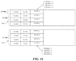
- FIG. 16 illustrates a method for configuring an HE-SIG-A and spatial reuse fields of the trigger-based PPDU according to another embodiment of the present invention.
- the SR fields for the first frequency band may be set to the same value as the SR fields for the second frequency band.
- STAs transmitting the trigger-based PPDU 510 , 520 may carry the SRP information obtained from the trigger frame through the SR field of the trigger-based PPDU 510 , 520 .
- the STA may repeatedly insert two pieces of SRP information into the SR fields.
- the SRP information for each subband obtained from the trigger frame may be a, b, c and d.
- a and b may be SRP information for the first frequency band
- c and d may be SRP information for the second frequency band.
- a, b, a, and b may be respectively contained in the first SR field to the fourth SR field of the trigger-based PPDU 510 transmitted on the first frequency band.
- c, d, c, and d may be respectively contained in the first SR field to the fourth SR field of the trigger-based PPDU 520 transmitted on the second frequency band. That is, the first SR field and the second SR field for the first frequency band are respectively set to the same values as the third SR field and the fourth SR field for the second frequency band.
- the first frequency band and the second frequency band may indicate a high (or low) physical frequency band and a low (or high) physical frequency band, respectively.
- the first frequency band and the second frequency band may indicate a band of the P80 channel and a band of the S80 channel, respectively.
- An OBSS terminal receiving the trigger-based PPDUs 510 , 520 obtains the first SRP from at least one of the first SR field and the third SR field of the received PPDUs 510 , 520 . That is, since the information indicated by the first SR field and the second SR field is the same as the information indicated by the third SR field and the fourth SR field, the ambiguity of the SR field identification of the OBSS terminal can be solved.
- the SRP information a, b, c, and d transmitted by the trigger frame can be set in various rules.
- a and b may represent SRPs for the low frequency band
- c and d may represent SRPs for the high frequency band.
- a and b may represent SRPs for the high frequency band and c and d may represent SRPs for the low frequency band. According to yet another embodiment, a and b may be set to the same values as c and d, respectively.
- FIG. 17 illustrates a method for configuring an HE-SIG-A and spatial reuse fields of the trigger-based PPDU according to yet another embodiment of the present invention.
- SR fields for the first frequency band and SR fields for the second frequency band may be identified through a physical signaling method.
- a cyclic shift value of the trigger-based PPDU 610 transmitted on the first frequency band may be set differently from a cyclic shift value of the trigger-based PPDU 620 transmitted on the second frequency band.
- the first cyclic shift value applied to the first frequency band and the second cyclic shift value applied to the second frequency band may be designated in advance. Accordingly, an OBSS terminal receiving the trigger-based PPDU 610 to which the first cyclic shift value is applied obtains SRP information for the corresponding subband from at least one of the first SR field and the second SR field of the corresponding PPDU 610 .
- an OBSS terminal receiving the trigger-based PPDU 620 to which the second cyclic shift value is applied obtains SRP information for the corresponding subband from at least one of the third SR field and the fourth SR field of the corresponding PPDU 620 .
- FIG. 18 illustrates a method for configuring an HE-SIG-A and spatial reuse fields of the trigger-based PPDU according to still another embodiment of the present invention.
- SR fields for the first frequency band and SR fields for the second frequency band may be identified through a physical signaling method.
- a modulation scheme applied to a specific field of the trigger-based PPDU 710 transmitted on the first frequency band may be set differently from a modulation scheme applied to a specific field of the trigger-based PPDU 720 transmitted on the second frequency band.
- the first modulation scheme applied to the specific field transmitted through the first frequency band and the second modulation scheme applied to the specific field transmitted through the second frequency band may be designated in advance.
- the specific field to which different modulation schemes are applied according to the frequency band may be a repeated L-SIG (RL-SIG).
- an OBSS terminal receiving the trigger-based PPDU 710 including the RL-SIG to which the first modulation scheme is applied obtains the SRP information for the corresponding subband from at least one of the first SR field and the second SR field of the PPDU 710 .
- an OBSS terminal receiving the trigger-based PPDU 720 including the RL-SIG to which the second modulation scheme is applied obtains the SRP information for the corresponding subband from at least one of the third SR field and the fourth SR field of the PPDU 720 .
- FIG. 19 illustrates a method for configuring an HE-SIG-A and spatial reuse fields of the trigger-based PPDU according to still yet another embodiment of the present invention.
- the HE-SIG-A of a PPDU in an HE format may contain a non-contiguous band indicator indicating whether the total bandwidth on which the PPDU is transmitted is non-contiguous. Accordingly, whether the total bandwidth on which the trigger-based PPDU(s) are transmitted is contiguous 160 MHz or non-contiguous 80+80 MHz can be identified through the non-contiguous band indicator.
- An OBSS terminal receiving the trigger-based PPDUs 810 , 820 may determine the SR operation based on the non-contiguous band indicator of the received PPDUs 810 , 820 . If the non-contiguous band indicator is set to 0 (i.e., if the total bandwidth on which the PPDU is transmitted is contiguous), the OBSS terminal can identify each subband constituting the total bandwidth on which the PPDU is transmitted and an SR field corresponding thereto. Accordingly, the OBSS terminal may perform the SR operation based on the obtained SR field. However, as shown in FIG.
- the OBSS terminal cannot identify each subband constituting the total bandwidth on which the PPDU is transmitted and an SR field corresponding thereto. Therefore, the OBSS terminal may not perform the above SR operation.
- the first frequency band and the second frequency band may indicate a high (or low) physical frequency band and a low (or high) physical frequency band, respectively.
- the first frequency band and the second frequency band may indicate a band of the P80 channel and a band of the S80 channel, respectively.
- FIGS. 20 and 21 illustrate another embodiment of a method for setting spatial reuse fields of a trigger-based PPDU.
- each SR field of the trigger-based PPDU may indicate an SRP for the individual subband in units of 40 MHz.
- the physical band that constitutes the total bandwidth is determined by a predetermined rule.
- an OBSS terminal receiving the trigger-based PPDU transmitted on a contiguous frequency band can identify the physical band on which the trigger-based PPDU(s) are transmitted.
- the physical bands that constitute the total bandwidth may not be predetermined.
- an OBSS terminal receiving the trigger-based PPDU transmitted on the non-contiguous frequency bands cannot identify which frequency band the SR fields of the corresponding PPDU are for. More specifically, when the total bandwidth on which the trigger-based PPDU(s) are transmitted is 80+80 MHz, the OBSS terminal cannot identify the set from which the SRP for the subband on which the PPDU is received can be obtained among the first set of SR fields (i.e., at least one of the first SR field and the second SR field) and the second set of SR fields (i.e., at least one of the third SR field and the fourth SR field). Accordingly, when the trigger-based PPDU is transmitted on non-contiguous frequency bands, there is a need for a method for resolving the ambiguity of the SR field identification of the OBSS terminals receiving it.
- FIG. 20 illustrates another embodiment of a method for setting spatial reuse fields of a trigger-based PPDU in order to solve such a problem.
- a representative value among SRPs for two 40 MHz bands corresponding to each other may be set to an SRP for the corresponding bands. More specifically, a representative value among the SRP for the first 40 MHz band and the SRP for the third 40 MHz band may be used as the first SRP for the first 40 MHz band and the third 40 MHz band.
- the first SR field and the third SR field of the trigger-based PPDU represent the same representative value.
- a representative value among the SRP for the second 40 MHz band and the SRP for the fourth 40 MHz band may be used as the second SRP for the second 40 MHz band and the fourth 40 MHz band.
- the second SR field and the fourth SR field of the trigger-based PPDU represent the same representative value.
- the first 40 MHz band and the second 40 MHz band constitute the first frequency band on which the trigger-based PPDU(s) are transmitted
- the third 40 MHz band and the fourth 40 MHz band constitute the second frequency band on which the trigger-based PPDU(s) are transmitted.
- a smaller value among the plurality of SRPs may be set as a representative value of the corresponding SRPs.
- An OBSS terminal receiving the trigger-based PPDU having a total bandwidth of 80+80 MHz may obtain the first SRP from at least one of the first SR field and the third SR field of the received PPDU, and may obtain the second SRP from at least one of the second SR field and the fourth SR field of the received PPDU. That is, since the information indicated by the first SR field and the second SR field is the same as the information indicated by the third SR field and the fourth SR field, the ambiguity of the SR field identification of the OBSS terminal can be solved.
- each SR field may indicate an SRP for the different subbands in 40 MHz units. That is, the first SR field indicates the SRP for the first 40 MHz band, the second SR field indicates the SRP for the second 40 MHz band, the third SR field indicates the SRP for the third 40 MHz band, and the fourth SR field indicates the SRP for the fourth 40 MHz band.
- the first 40 MHz band to the fourth 40 MHz band constitute the total bandwidth 160 MHz on which the trigger-based PPDU(s) are transmitted.
- FIG. 21 illustrates yet another embodiment of a method for setting and using spatial reuse fields of a trigger-based PPDU.
- each SR field of the trigger-based PPDU may indicate an SRP for different subbands
- an OBSS terminal receiving the PPDU may select an SRP for the SR operation of the corresponding subband among SRPs indicated by a plurality of SR fields.
- each SR field may indicate an SRP for the different subbands in units of 40 MHz. That is, the first SR field indicates the SRP for the first 40 MHz band, the second SR field indicates the SRP for the second 40 MHz band, the third SR field indicates the SRP for the third 40 MHz band, and the fourth SR field indicates the SRP for the fourth 40 MHz band.
- the first 40 MHz band and the second 40 MHz band constitute the first frequency band on which the trigger-based PPDU(s) are transmitted
- the third 40 MHz band and the fourth 40 MHz band constitute the second frequency band on which the trigger-based PPDU(s) are transmitted.
- An OBSS terminal receiving the trigger-based PPDU having a total bandwidth of 80+80 MHz uses a smaller value between the two SR fields corresponding to each other as an SRP for the corresponding subband. That is, the smaller value between the first SR field value and the third SR field value is used for the SRP for the first 40 MHz band and/or the third 40 MHz band. In addition, the smaller value between the second SR field value and the fourth SR field value is used for the SRP for the second 40 MHz band and/or the fourth 40 MHz band.
- FIG. 22 illustrates a method for configuring an HE-SIG-A and spatial reuse fields of a trigger-based PPDU according to a further embodiment of the present invention.
- the SR operation may be restricted in the trigger-based PPDU transmitted on the non-contiguous frequency bands. More specifically, the SR fields of the trigger-based PPDUs 910 , 920 transmitted on the 80+80 MHz band may indicate a predetermined value not allowing the SR operation. To this end, the AP may carry an SRP indicating a predetermined value not allowing the SR operation through the trigger frame.
- FIG. 23 illustrates a method for signaling spatial reuse fields of a trigger-based PPDU according to another embodiment of the present invention.
- the SR field may indicate an SRP for a subband of 20 MHz bandwidth.
- the value indicated by each SR field is the same as that illustrated in FIG. 13 .
- the values of the SR fields for the first 80 MHz frequency band may be set different from the values of the SR fields for the second 80 MHz frequency band. That is, the first SR field to the fourth SR field of the trigger-based PPDU transmitted on the first frequency band respectively indicate SRPs for the first 20 MHz band to the fourth 20 MHz band of the first frequency band. In addition, the first SR field to the fourth SR field of the trigger-based PPDU transmitted on the second frequency band respectively indicate SRPs for the first 20 MHz band to the fourth 20 MHz band of the second frequency band. In this case, the first SR field to the fourth SR field for the first frequency band and the first SR field to the fourth SR field for the second frequency band may be determined independently from each other.
- the length of the trigger frame may be determined to be variable according to the total bandwidth information. That is, if the total bandwidth is 20 MHz, 40 MHz, or 80 MHz, the trigger frame carries a total of 16 bits of SRP, and if the total bandwidth is 160 MHz (or 80+80 MHz), the trigger frame carries a total of 32 bits of SRP.
- FIG. 24 illustrates a method for signaling a bandwidth field according to an embodiment of the present invention.
- whether or not the total bandwidth of the transmitted PPDU is contiguous may be signaled via the HE-SIG-A.
- the HE-SIG-A of a PPDU in an HE format may contain a non-contiguous band indicator.
- the total bandwidth on which the trigger-based PPDU(s) are transmitted is contiguous 160 MHz or non-contiguous 80+80 MHz can be identified through the non-contiguous band indicator.
- whether the total bandwidth of the transmitted PPDU is contiguous may be signaled through the bandwidth field of the HE-SIG-A as shown in FIG. 24 .
- the non-contiguous bandwidth may be indicated via a predetermined index of the bandwidth field of the HE-SIG-A.
- the indices 0, 1, 2, and 3 of the bandwidth field may represent 20 MHz, 40 MHz, 80 MHz, and 160 MHz, respectively.
- the index 4 of the bandwidth field may represent non-contiguous 80+80 MHz.
- an OBSS terminal receiving the PPDU may perform an SR operation for 160 MHz.
- the bandwidth field of the trigger-based PPDU indicates non-contiguous 80+80 MHz
- the OBSS terminal may perform an SR operation for 80 MHz including the subband on which the corresponding PPDU is received.
- whether the total bandwidth of the transmitted PPDU is contiguous may be identified according to whether the corresponding SR fields are set to the same value. For example, when the bandwidth field of the trigger-based PPDU indicates 160 MHz, and the first SR field and the second SR field are set to the same values as the third SR field and the fourth SR field, respectively, the total bandwidth on which the trigger-based PPDU(s) are transmitted may be identified as 80+80 MHz.
- the present invention is described by using the wireless LAN communication as an example, the present invention is not limited thereto and the present invention may be similarly applied even to other communication systems such as cellular communication, and the like. Further, the method, the apparatus, and the system of the present invention are described in association with the specific embodiments, but some or all of the components and operations of the present invention may be implemented by using a computer system having universal hardware architecture.
- the detailed described embodiments of the present invention may be implemented by various means.
- the embodiments of the present invention may be implemented by a hardware, a firmware, a software, or a combination thereof.
- the method according to the embodiments of the present invention may be implemented by one or more of Application Specific Integrated Circuits (ASICSs), Digital Signal Processors (DSPs), Digital Signal Processing Devices (DSPDs), Programmable Logic Devices (PLDs), Field Programmable Gate Arrays (FPGAs), processors, controllers, micro-controllers, micro-processors, and the like.
- ASICSs Application Specific Integrated Circuits
- DSPs Digital Signal Processors
- DSPDs Digital Signal Processing Devices
- PLDs Programmable Logic Devices
- FPGAs Field Programmable Gate Arrays
- processors controllers, micro-controllers, micro-processors, and the like.
- the method according to the embodiments of the present invention may be implemented by a module, a procedure, a function, or the like which performs the operations described above.
- Software codes may be stored in a memory and operated by a processor.
- the processor may be equipped with the memory internally or externally and the memory may exchange data with the processor by various publicly known means.
Abstract
Description
SRP=TXPWR_AP+Acceptable Receiver Interference Level_AP [Equation 1]
TXPWR_STA<SRP−RSSI_TriggerFrame_at_STA [Equation 2]
SRP_x=2*min(SRP_xa,SRP_xb)
where
SRP_xa=TX PWR_AP,xa+Acceptable Receiver Interference Level_AP,xa
SRP_xb=TX PWR_AP,xb+Acceptable Receiver Interference Level_AP,xb [Equation 3]
SRP_x=TX PWR_AP,x+Acceptable Receiver Interference Level_AP,x
where
TX PWR_AP,x=2*min(TX PWR_AP,xa,TX PWR_AP,xb)
Acceptable Receiver Interference Level_AP,x=2*min(Acceptable Receiver Interference Level_AP,xa,Acceptable Receiver Interference Level_AP,xb) [Equation 4]
SRP_x=min(SRP_xa,SRP_xb)
where
SRP_xa=TX PWR_AP,xa+Acceptable Receiver Interference Level_AP,xa
SRP_xb=TX PWR_AP,xb+Acceptable Receiver Interference Level_AP,xb [Equation 5]
SRP_x=TX PWR_AP,x+Acceptable Receiver Interference Level_AP,x
where
TX PWR_AP,x=min(TX PWR_AP,xa,TX PWR_AP,xb)
Acceptable Receiver Interference Level_AP,x=min(Acceptable Receiver Interference Level_AP,xa,Acceptable Receiver Interference Level_AP,xb) [Equation 6]
Claims (18)
Priority Applications (4)
| Application Number | Priority Date | Filing Date | Title |
|---|---|---|---|
| US16/813,660 US11153759B2 (en) | 2016-04-02 | 2020-03-09 | Wireless communication method and wireless communication terminal for spatial reuse of overlapped basic service set |
| US16/812,375 US11140556B2 (en) | 2016-04-02 | 2020-03-09 | Wireless communication method and wireless communication terminal for spatial reuse of overlapped basic service set |
| US17/481,157 US11871241B2 (en) | 2016-04-02 | 2021-09-21 | Wireless communication method and wireless communication terminal for spatial reuse of overlapped basic service set |
| US18/225,132 US20230370853A1 (en) | 2016-04-02 | 2023-07-23 | Wireless communication method and wireless communication terminal for spatial reuse of overlapped basic service set |
Applications Claiming Priority (9)
| Application Number | Priority Date | Filing Date | Title |
|---|---|---|---|
| KR10-2016-0040551 | 2016-04-02 | ||
| KR20160040551 | 2016-04-02 | ||
| KR20160074091 | 2016-06-14 | ||
| KR10-2016-0074091 | 2016-06-14 | ||
| KR20160086044 | 2016-07-07 | ||
| KR10-2016-0086044 | 2016-07-07 | ||
| KR20160093813 | 2016-07-23 | ||
| KR10-2016-0093813 | 2016-07-23 | ||
| PCT/KR2017/003662 WO2017171531A1 (en) | 2016-04-02 | 2017-04-03 | Wireless communication method and wireless communication terminal for spatial reuse of overlapped basic service set |
Related Parent Applications (1)
| Application Number | Title | Priority Date | Filing Date |
|---|---|---|---|
| PCT/KR2017/003662 Continuation WO2017171531A1 (en) | 2016-04-02 | 2017-04-03 | Wireless communication method and wireless communication terminal for spatial reuse of overlapped basic service set |
Related Child Applications (2)
| Application Number | Title | Priority Date | Filing Date |
|---|---|---|---|
| US16/812,375 Continuation US11140556B2 (en) | 2016-04-02 | 2020-03-09 | Wireless communication method and wireless communication terminal for spatial reuse of overlapped basic service set |
| US16/813,660 Continuation US11153759B2 (en) | 2016-04-02 | 2020-03-09 | Wireless communication method and wireless communication terminal for spatial reuse of overlapped basic service set |
Publications (2)
| Publication Number | Publication Date |
|---|---|
| US20190028898A1 US20190028898A1 (en) | 2019-01-24 |
| US10623964B2 true US10623964B2 (en) | 2020-04-14 |
Family
ID=59966090
Family Applications (5)
| Application Number | Title | Priority Date | Filing Date |
|---|---|---|---|
| US16/141,973 Active US10623964B2 (en) | 2016-04-02 | 2018-09-26 | Wireless communication method and wireless communication terminal for spatial reuse of overlapped basic service set |
| US16/812,375 Active US11140556B2 (en) | 2016-04-02 | 2020-03-09 | Wireless communication method and wireless communication terminal for spatial reuse of overlapped basic service set |
| US16/813,660 Active US11153759B2 (en) | 2016-04-02 | 2020-03-09 | Wireless communication method and wireless communication terminal for spatial reuse of overlapped basic service set |
| US17/481,157 Active US11871241B2 (en) | 2016-04-02 | 2021-09-21 | Wireless communication method and wireless communication terminal for spatial reuse of overlapped basic service set |
| US18/225,132 Pending US20230370853A1 (en) | 2016-04-02 | 2023-07-23 | Wireless communication method and wireless communication terminal for spatial reuse of overlapped basic service set |
Family Applications After (4)
| Application Number | Title | Priority Date | Filing Date |
|---|---|---|---|
| US16/812,375 Active US11140556B2 (en) | 2016-04-02 | 2020-03-09 | Wireless communication method and wireless communication terminal for spatial reuse of overlapped basic service set |
| US16/813,660 Active US11153759B2 (en) | 2016-04-02 | 2020-03-09 | Wireless communication method and wireless communication terminal for spatial reuse of overlapped basic service set |
| US17/481,157 Active US11871241B2 (en) | 2016-04-02 | 2021-09-21 | Wireless communication method and wireless communication terminal for spatial reuse of overlapped basic service set |
| US18/225,132 Pending US20230370853A1 (en) | 2016-04-02 | 2023-07-23 | Wireless communication method and wireless communication terminal for spatial reuse of overlapped basic service set |
Country Status (4)
| Country | Link |
|---|---|
| US (5) | US10623964B2 (en) |
| KR (5) | KR102128286B1 (en) |
| CN (4) | CN109076614B (en) |
| WO (1) | WO2017171531A1 (en) |
Cited By (1)
| Publication number | Priority date | Publication date | Assignee | Title |
|---|---|---|---|---|
| US11323216B2 (en) * | 2019-02-26 | 2022-05-03 | Canon Kabushiki Kaisha | Communication apparatus that selectively permits spatial reuse parameter based communication, method of controlling communication apparatus, and non-transitory computer-readable storage medium |
Families Citing this family (26)
| Publication number | Priority date | Publication date | Assignee | Title |
|---|---|---|---|---|
| KR102505004B1 (en) | 2015-10-20 | 2023-03-03 | 주식회사 윌러스표준기술연구소 | Wireless communication method and wireless communication terminal in high-density environment including overlapped basic service set |
| KR102371753B1 (en) | 2015-11-03 | 2022-03-11 | 주식회사 윌러스표준기술연구소 | Wireless communication method and wireless communication terminal in high-density environment including overlapping basic service set |
| CN115426089A (en) | 2016-03-04 | 2022-12-02 | 韦勒斯标准与技术协会公司 | Wireless communication method and wireless communication terminal |
| EP4110000A1 (en) | 2016-04-02 | 2022-12-28 | Wilus Institute of Standards and Technology Inc. | Wireless communication method and wireless communication terminal using basic service set identification information determination of received frame |
| KR102128286B1 (en) | 2016-04-02 | 2020-06-30 | 주식회사 윌러스표준기술연구소 | Wireless communication method and wireless communication terminal for spatial reuse of nested basic service set |
| KR102344180B1 (en) | 2016-06-14 | 2021-12-28 | 주식회사 윌러스표준기술연구소 | Wireless communication method and wireless communication terminal for spatial reuse operation |
| EP3714619A4 (en) | 2017-11-21 | 2021-01-27 | ZTE Corporation | Wireless communication using spatial reuse |
| CN111727616A (en) * | 2018-02-28 | 2020-09-29 | 松下电器(美国)知识产权公司 | Wireless communication device and wireless communication method |
| US11411635B2 (en) * | 2018-03-19 | 2022-08-09 | Mediatek Singapore Pte. Ltd. | Spatial reuse in WLAN multi-AP network |
| KR102572878B1 (en) * | 2018-11-16 | 2023-08-30 | 삼성전자 주식회사 | Wireless communication device using spaital reuse and data communiction method using the same |
| CN112469088A (en) * | 2019-09-09 | 2021-03-09 | 华为技术有限公司 | OFDMA (orthogonal frequency division multiple Access) hybrid transmission method and device |
| US11671837B2 (en) * | 2019-10-17 | 2023-06-06 | Mediatek Singapore Pte. Ltd. | Multi-access point coordinated spatial reuse protocol and algorithm |
| WO2021089674A1 (en) * | 2019-11-05 | 2021-05-14 | Sony Corporation | Access points, station and corresponding methods |
| US11172368B2 (en) * | 2019-11-15 | 2021-11-09 | Cisco Technology, Inc. | Location-aware spatial reuse |
| US20220217027A9 (en) * | 2020-02-22 | 2022-07-07 | Nxp Usa, Inc. | Wireless communication device |
| US20230130569A1 (en) * | 2020-03-14 | 2023-04-27 | Wilus Institute Of Standards And Technology Inc. | Wireless communication terminal and method for transmitting or receiving data in wireless communication system |
| US20230156525A1 (en) * | 2020-04-10 | 2023-05-18 | Lg Electronics Inc. | Transmission power adjustment for str operation |
| US11582007B2 (en) * | 2020-05-06 | 2023-02-14 | Mediatek Inc. | Apparatuses and methods for resource unit (RU) allocation signaling to support trigger-based physical layer protocol data unit (TB PPDU) with multi-RU |
| CN116171621A (en) * | 2020-08-05 | 2023-05-26 | 苹果公司 | System and method for dynamic scheduling in a new radio with user equipment |
| TWI749793B (en) * | 2020-09-30 | 2021-12-11 | 瑞昱半導體股份有限公司 | Device and method of handling a transmission based on spatial reuse |
| JP2024506354A (en) * | 2021-02-10 | 2024-02-13 | ウィルス インスティテュート オブ スタンダーズ アンド テクノロジー インコーポレイティド | Wireless communication method using multilink and wireless communication terminal using the same |
| KR20230160791A (en) * | 2021-03-25 | 2023-11-24 | 엘지전자 주식회사 | Method and apparatus for configuring special user information field in trigger frame even when triggering only HE TB PPDU in wireless LAN system |
| CN116390215B (en) * | 2021-04-01 | 2023-11-28 | 华为技术有限公司 | Spatial multiplexing method, apparatus, device and medium |
| US11818706B2 (en) * | 2021-04-27 | 2023-11-14 | Cisco Technology, Inc. | Mesh performance using overlapping basic service set (OBSS) coloring and transmission scheduling |
| US20230239699A1 (en) * | 2022-01-24 | 2023-07-27 | Mediatek Inc. | Spatial-reuse classification in mesh network |
| CN114513841B (en) * | 2022-04-18 | 2022-07-01 | 国网四川省电力公司电力科学研究院 | Multi-AP cooperation power control method and system for power emergency communication system |
Citations (36)
| Publication number | Priority date | Publication date | Assignee | Title |
|---|---|---|---|---|
| US8971213B1 (en) | 2011-10-20 | 2015-03-03 | Cisco Technology, Inc. | Partial association identifier computation in wireless networks |
| US20150078299A1 (en) | 2013-09-18 | 2015-03-19 | Qualcomm Incorporated | Deferral based on bssid information |
| WO2015050311A1 (en) | 2013-10-05 | 2015-04-09 | 엘지전자 주식회사 | Operation method and apparatus using sectorized transmission opportunity in wireless lan system |
| US20150103767A1 (en) | 2012-06-27 | 2015-04-16 | Lg Electronics Inc. | Method for indicating channel access type in wireless communication system, and apparatus therefor |
| WO2015093704A1 (en) | 2013-12-20 | 2015-06-25 | 엘지전자 주식회사 | Method and device for transceiving frame comprisng partial association identifier in wireless lan system |
| WO2015112780A1 (en) | 2014-01-24 | 2015-07-30 | Mediatek Singapore Pte. Ltd. | Adaptive cca and tx power level adjustment for dense deployment of wireless networks |
| WO2015120488A1 (en) | 2014-02-10 | 2015-08-13 | Mediatek Inc. | Method for identifying source bss in wlan |
| US20150282043A1 (en) * | 2014-03-28 | 2015-10-01 | Zte Corporation | Techniques for fast delivery of radio information |
| WO2016003056A1 (en) | 2014-07-03 | 2016-01-07 | 엘지전자(주) | Method and device for transmitting uplink multi-user data in wireless communication system |
| KR20160006681A (en) | 2013-05-02 | 2016-01-19 | 엘지전자 주식회사 | Method for sensing channel dynamically in wireless lan system and apparatus therefor |
| US20160050691A1 (en) | 2014-08-12 | 2016-02-18 | Mediatek Inc. | Method to Improve Channel Access Opportunity in a Wireless Communications System |
| WO2016029876A1 (en) | 2014-08-29 | 2016-03-03 | Mediatek Inc. | Prioritized channel access schemes with spatial reuse consideration |
| WO2016036138A1 (en) | 2014-09-04 | 2016-03-10 | 엘지전자 주식회사 | Method and device for triggering plurality of ps-poll frames in wireless lan |
| US20160088126A1 (en) | 2014-09-19 | 2016-03-24 | Qualcomm Incorporated | Methods and apparatus for packet acquisition in mixed-rate wireless communication networks |
| US20160249366A1 (en) | 2013-10-22 | 2016-08-25 | Lg Electronics Inc. | Method and device for preventing interference in overlapping service area |
| US20160374087A1 (en) | 2015-06-16 | 2016-12-22 | Mediatek Inc. | Enhanced channel contention schemes for high-efficiency wlan |
| US20170006541A1 (en) | 2015-07-01 | 2017-01-05 | Po-Kai Huang | Determining two network allocation vector settings |
| US20170164371A1 (en) | 2015-12-08 | 2017-06-08 | Lg Electronics Inc. | Method of performing rts/cts procedure in wireless lan system and apparatus thereof |
| US20170188376A1 (en) | 2015-12-28 | 2017-06-29 | Newracom, Inc. | Multiple network allocation vector operation |
| US20170201981A1 (en) | 2016-01-13 | 2017-07-13 | Intel IP Corporation | Network allocation vector settings for multi-user operation |
| US20170230981A1 (en) | 2015-06-18 | 2017-08-10 | Lg Electronics Inc. | Method and apparatus for performing uplink transmission in wireless lan system |
| US20170289987A1 (en) | 2014-11-19 | 2017-10-05 | Newracom, Inc. | Method and apparatus for processing ppdu based on bss identification information in a high efficiency wireless lan |
| WO2017171531A1 (en) | 2016-04-02 | 2017-10-05 | 주식회사 윌러스표준기술연구소 | Wireless communication method and wireless communication terminal for spatial reuse of overlapped basic service set |
| US20170289819A1 (en) | 2016-03-29 | 2017-10-05 | Lg Electronics Inc. | Vht frame including spatial reuse parameter in he wlan |
| WO2017171530A1 (en) | 2016-04-02 | 2017-10-05 | 주식회사 윌러스표준기술연구소 | Wireless communication method and wireless communication terminal using basic service set identification information determination of received frame |
| US20170295560A1 (en) | 2015-05-20 | 2017-10-12 | Lg Electronics Inc. | Method for managing nav in wireless lan system and device for same |
| US20180014327A1 (en) | 2016-07-06 | 2018-01-11 | Neuromeka | Uplink ppdu transmission |
| US20180146426A1 (en) | 2016-11-22 | 2018-05-24 | Neuromeka | Transmitting ppdu |
| US20180220456A1 (en) * | 2015-07-29 | 2018-08-02 | Lg Electronics Inc. | Method and apparatus for transmitting data in wireless communication system |
| US20180227952A1 (en) * | 2015-06-05 | 2018-08-09 | Lg Electronics Inc. | Method for transmitting data in wireless communication system and apparatus therefor |
| US20180317173A1 (en) | 2015-11-19 | 2018-11-01 | Lg Electronics Inc. | Method for operating in power-save mode in wireless lan system and apparatus for method |
| US20180317170A1 (en) * | 2017-04-26 | 2018-11-01 | Intel IP Corporation | Power restriction period for high efficiency wifi |
| US10128966B1 (en) * | 2016-05-06 | 2018-11-13 | Marvell International Ltd. | Method and apparatus for communication |
| US20180359807A1 (en) | 2015-12-11 | 2018-12-13 | Lg Electronics Inc. | Method for transmitting and receiving frame in wireless lan system, and apparatus therefor |
| US20190261419A1 (en) | 2015-12-14 | 2019-08-22 | Newracom, Inc. | Multiple network allocation vector operation |
| US20190327741A1 (en) | 2016-12-30 | 2019-10-24 | Zte Corporation | Spatial reuse method and device |
Family Cites Families (63)
| Publication number | Priority date | Publication date | Assignee | Title |
|---|---|---|---|---|
| US8385289B2 (en) | 2001-10-23 | 2013-02-26 | Alcatel Lucent | Procedure processing method for packet mode locating services in a mobile radiocommunication system |
| KR101610305B1 (en) | 2009-03-20 | 2016-04-20 | 삼성전자주식회사 | Apparatus and method for reducing inter-cell interference in multiple input multiple output system |
| KR101534865B1 (en) | 2009-06-23 | 2015-07-27 | 엘지전자 주식회사 | Method of performing link adaptation procedure |
| US8787284B2 (en) * | 2010-03-15 | 2014-07-22 | Lg Electronics Inc. | Method and apparatus for transmitting frame in WLAN system |
| US8483741B1 (en) * | 2010-05-03 | 2013-07-09 | Qualcomm Incorporated | Mitigation of inter-network interference to enable channel reuse |
| US8531980B2 (en) | 2010-06-29 | 2013-09-10 | Intel Corporation | Multi-channel communication station for communicating a multi-channel PPDU and methods of reducing collisions on secondary channels in multi-channel wireless networks |
| US8553605B2 (en) | 2010-09-10 | 2013-10-08 | Qualcomm Incorporated | Packet identification for power saving in wireless communication networks |
| US9271136B2 (en) | 2010-11-19 | 2016-02-23 | Qualcomm Incorporated | Probe messaging for direct link connections |
| US9414413B2 (en) | 2011-06-08 | 2016-08-09 | Lg Electronics Inc. | Method and device for transmitting a frame using a multiple physical layer in a wireless LAN system |
| KR101898901B1 (en) | 2011-06-08 | 2018-09-14 | 마벨 월드 트레이드 리미티드 | Efficient transmission for low data rate wlan |
| KR101558112B1 (en) | 2011-08-07 | 2015-10-06 | 엘지전자 주식회사 | Method of channel access in wireless local area network and appratus for the same |
| JP6121430B2 (en) * | 2011-10-18 | 2017-04-26 | エルジー エレクトロニクス インコーポレイティド | Method and apparatus for mitigating inter-cell interference in a wireless communication system |
| KR102083964B1 (en) | 2012-02-05 | 2020-03-03 | 엘지전자 주식회사 | Method and apparatus for channel access via null data packet frame in wireless lan system |
| KR101585366B1 (en) | 2012-02-14 | 2016-01-13 | 엘지전자 주식회사 | Method for transmitting data units in wireless lan systems and apparatus for supporting same |
| EP2820909B1 (en) * | 2012-03-01 | 2017-09-06 | Interdigital Patent Holdings, Inc. | Multi-user parallel channel access in wlan systems |
| US9585058B2 (en) | 2012-04-24 | 2017-02-28 | Lg Electronics Inc. | Method and apparatus for transmitting and receiving frame including partial association identifier in wireless LAN system |
| US10932229B2 (en) | 2012-04-30 | 2021-02-23 | Interdigital Patent Holdings, Inc. | Method and apparatus for supporting coordinated orthogonal block-based resource allocation (COBRA) operations |
| KR101553857B1 (en) | 2012-08-16 | 2015-09-17 | 주식회사 케이티 | Method for channel access in wireless local area network system |
| KR20140023850A (en) | 2012-08-17 | 2014-02-27 | 주식회사 케이티 | Method for channel access in wireless local area network system |
| KR20140035841A (en) * | 2012-09-14 | 2014-03-24 | 주식회사 케이티 | Method for transmitting data in wireless local area network system |
| KR101561117B1 (en) | 2012-09-20 | 2015-10-16 | 주식회사 케이티 | Method for active scanning in wireless local area network system |
| WO2014158171A1 (en) | 2013-03-28 | 2014-10-02 | Hewlett-Packard Development Company, L.P. | Making a frame receive decision in a receiver phy layer |
| US9439161B2 (en) | 2013-07-17 | 2016-09-06 | Qualcomm Incorporated | Physical layer design for uplink (UL) multiuser multiple-input, multiple-output (MU-MIMO) in wireless local area network (WLAN) systems |
| CN105379145A (en) * | 2013-08-12 | 2016-03-02 | Kt株式会社 | Method and device for transmitting data in WLAN system |
| US9736829B2 (en) | 2013-10-14 | 2017-08-15 | Qualcomm Incorporated | Downlink control management in an unlicensed or shared spectrum |
| US9807794B2 (en) * | 2013-10-23 | 2017-10-31 | Qualcomm, Incorporated | Systems, methods and devices for dynamically setting response indication deferral in wireless networks |
| KR20150052798A (en) | 2013-11-06 | 2015-05-14 | 주식회사 케이티 | Method for transmitting and receiving data in wireless local area network system and apparatus therefor |
| KR20150054624A (en) | 2013-11-11 | 2015-05-20 | 인텔렉추얼디스커버리 주식회사 | Access point, station and method of connecting the access point and the station |
| CA2930899A1 (en) | 2013-11-25 | 2015-05-28 | Lg Electronics Inc. | Method and device for transmitting uplink frame in wireless lan |
| US20160381565A1 (en) * | 2013-11-27 | 2016-12-29 | Interdigital Patent Holdings, Inc. | Interference mitigation in multi-provider wlan networks |
| KR102144288B1 (en) * | 2013-12-20 | 2020-08-13 | 한국전자통신연구원 | Method for transmitting and receiving data in wireless local area network and apparatus for the same |
| SG11201605389SA (en) | 2013-12-31 | 2016-08-30 | Agency Science Tech & Res | Mobile radio communication devices and methods for controlling a mobile radio communication device |
| KR102211170B1 (en) | 2014-04-25 | 2021-02-01 | 뉴라컴 인코포레이티드 | Method and apparatus for transmitting frame |
| KR20150124389A (en) | 2014-04-28 | 2015-11-05 | 뉴라컴 인코포레이티드 | Signaling method |
| CN110958716B (en) * | 2014-05-13 | 2023-07-28 | 韦勒斯标准与技术协会公司 | Wireless communication method for clear channel assessment and wireless communication terminal using the same |
| KR20160004950A (en) * | 2014-07-04 | 2016-01-13 | 뉴라컴 인코포레이티드 | Frame transmitting method and frame receiving method |
| KR102283162B1 (en) | 2014-08-07 | 2021-07-29 | 주식회사 윌러스표준기술연구소 | Wireless communication method and wireless communication terminal |
| KR102378708B1 (en) * | 2014-08-08 | 2022-03-25 | 한국전자통신연구원 | Operation method of station in wireless local area network |
| KR20160019383A (en) * | 2014-08-11 | 2016-02-19 | 뉴라컴 인코포레이티드 | Physical layer protocol data unit format in a high efficiency wireless lan |
| KR20160019867A (en) * | 2014-08-12 | 2016-02-22 | 뉴라컴 인코포레이티드 | Transmission power control for device in high efficiency wireless lan |
| CN112492701A (en) | 2014-08-18 | 2021-03-12 | 韦勒斯标准与技术协会公司 | Wireless communication method for simultaneous data communication and wireless communication terminal using the same |
| CN111711592B (en) * | 2014-08-25 | 2023-06-20 | 韦勒斯标准与技术协会公司 | Wireless communication method and wireless communication terminal using the same |
| KR20160028974A (en) * | 2014-09-03 | 2016-03-14 | 뉴라컴 인코포레이티드 | Operation method of station in wireless local area network |
| US10211901B2 (en) * | 2014-09-11 | 2019-02-19 | Interdigital Patent Holdings, Inc. | Wireless communications method and apparatus for spatial sharing using carrier sense multiple access wireless medium access |
| EP3937417B1 (en) | 2014-09-28 | 2022-08-24 | LG Electronics Inc. | Method for supporting flexible resource allocation in wireless communication system, and apparatus therefor |
| KR20160047405A (en) | 2014-10-22 | 2016-05-02 | 주식회사 윌러스표준기술연구소 | Wireless communication method and wireless communication terminal for packet auto detection |
| KR20160055718A (en) | 2014-11-10 | 2016-05-18 | 뉴라컴 인코포레이티드 | Method for transmitting and receiving frame in wireless local area network |
| WO2016085243A1 (en) | 2014-11-27 | 2016-06-02 | 한국전자통신연구원 | Method for operating station in wireless lan |
| KR20220157520A (en) | 2015-02-17 | 2022-11-29 | 주식회사 윌러스표준기술연구소 | Signaling method for multi-user transmission, and wireless communication termianl and wireless communication method using same |
| US10182361B1 (en) * | 2015-04-09 | 2019-01-15 | Newracom, Inc. | Receiver behavior for uplink multi-user transmission in wireless LAN systems |
| CN104853375B (en) | 2015-05-14 | 2018-03-09 | 江苏中兴微通信息科技有限公司 | The sending method of beacon frame collision is avoided in a kind of enhanced wireless LAN |
| US9826548B2 (en) | 2015-06-05 | 2017-11-21 | Telefonaktiebolaget L M Ericsson (Publ) | Station, an access point and methods therein for handling transmissions in a wireless communications network |
| WO2017012182A1 (en) | 2015-07-17 | 2017-01-26 | 华为技术有限公司 | Method for setting nav in wireless communication system, and related device |
| US10111226B2 (en) | 2015-08-26 | 2018-10-23 | Qualcomm Incorporated | Techniques to identify packets associated with an overlapping basic service set |
| US10257857B2 (en) | 2015-09-28 | 2019-04-09 | Newracom, Inc. | Apparatus and methods for TXOP duration field in PHY header |
| WO2017074024A1 (en) | 2015-10-26 | 2017-05-04 | 엘지전자 주식회사 | Method for updating nav in wireless lan system and apparatus therefor |
| US10470128B2 (en) | 2015-11-18 | 2019-11-05 | Newracom, Inc. | Early detection procedure of high-efficiency frame and decision timing for spatial reuse |
| US10171420B2 (en) | 2015-12-23 | 2019-01-01 | Intel IP Corporation | Spatial reuse for uplink multiuser transmissions |
| KR102344180B1 (en) | 2016-06-14 | 2021-12-28 | 주식회사 윌러스표준기술연구소 | Wireless communication method and wireless communication terminal for spatial reuse operation |
| US10136349B2 (en) | 2016-06-20 | 2018-11-20 | Futurewei Technologies, Inc. | System and method for changing an identifier of a basic service set |
| JP7009484B2 (en) | 2017-01-09 | 2022-01-25 | ウィルス インスティテュート オブ スタンダーズ アンド テクノロジー インコーポレイティド | Wireless communication method and wireless communication terminal for signaling multi-user packets |
| US11039598B2 (en) | 2018-03-26 | 2021-06-22 | Dennis D. Ranck | Pet watering system |
| US11032787B2 (en) | 2018-04-02 | 2021-06-08 | Nxp Usa, Inc. | Basic service set (BSS) color in null data packet (NDP) ranging |
-
2017
- 2017-04-03 KR KR1020187027723A patent/KR102128286B1/en active IP Right Grant
- 2017-04-03 KR KR1020207018342A patent/KR102239519B1/en active IP Right Grant
- 2017-04-03 KR KR1020217010350A patent/KR102435189B1/en active IP Right Grant
- 2017-04-03 KR KR1020227028595A patent/KR20220122776A/en not_active Application Discontinuation
- 2017-04-03 WO PCT/KR2017/003662 patent/WO2017171531A1/en active Application Filing
- 2017-04-03 CN CN201780022351.4A patent/CN109076614B/en active Active
- 2017-04-03 CN CN202210872516.XA patent/CN115379460A/en active Pending
- 2017-04-03 CN CN202210858332.8A patent/CN115379459A/en active Pending
- 2017-04-03 CN CN202210857580.0A patent/CN115379458A/en active Pending
- 2017-04-03 KR KR1020207018343A patent/KR102164966B1/en active IP Right Grant
-
2018
- 2018-09-26 US US16/141,973 patent/US10623964B2/en active Active
-
2020
- 2020-03-09 US US16/812,375 patent/US11140556B2/en active Active
- 2020-03-09 US US16/813,660 patent/US11153759B2/en active Active
-
2021
- 2021-09-21 US US17/481,157 patent/US11871241B2/en active Active
-
2023
- 2023-07-23 US US18/225,132 patent/US20230370853A1/en active Pending
Patent Citations (39)
| Publication number | Priority date | Publication date | Assignee | Title |
|---|---|---|---|---|
| US8971213B1 (en) | 2011-10-20 | 2015-03-03 | Cisco Technology, Inc. | Partial association identifier computation in wireless networks |
| US20150103767A1 (en) | 2012-06-27 | 2015-04-16 | Lg Electronics Inc. | Method for indicating channel access type in wireless communication system, and apparatus therefor |
| KR20160006681A (en) | 2013-05-02 | 2016-01-19 | 엘지전자 주식회사 | Method for sensing channel dynamically in wireless lan system and apparatus therefor |
| US20150078299A1 (en) | 2013-09-18 | 2015-03-19 | Qualcomm Incorporated | Deferral based on bssid information |
| WO2015050311A1 (en) | 2013-10-05 | 2015-04-09 | 엘지전자 주식회사 | Operation method and apparatus using sectorized transmission opportunity in wireless lan system |
| EP3054736A1 (en) | 2013-10-05 | 2016-08-10 | LG Electronics Inc. | Operation method and apparatus using sectorized transmission opportunity in wireless lan system |
| US20160249366A1 (en) | 2013-10-22 | 2016-08-25 | Lg Electronics Inc. | Method and device for preventing interference in overlapping service area |
| WO2015093704A1 (en) | 2013-12-20 | 2015-06-25 | 엘지전자 주식회사 | Method and device for transceiving frame comprisng partial association identifier in wireless lan system |
| EP3086484A1 (en) | 2013-12-20 | 2016-10-26 | LG Electronics Inc. | Method and device for transceiving frame comprisng partial association identifier in wireless lan system |
| WO2015112780A1 (en) | 2014-01-24 | 2015-07-30 | Mediatek Singapore Pte. Ltd. | Adaptive cca and tx power level adjustment for dense deployment of wireless networks |
| WO2015120488A1 (en) | 2014-02-10 | 2015-08-13 | Mediatek Inc. | Method for identifying source bss in wlan |
| US20160353275A1 (en) | 2014-02-10 | 2016-12-01 | Mediatek Inc. | Method for identifying source bss in wlan |
| US20150282043A1 (en) * | 2014-03-28 | 2015-10-01 | Zte Corporation | Techniques for fast delivery of radio information |
| WO2016003056A1 (en) | 2014-07-03 | 2016-01-07 | 엘지전자(주) | Method and device for transmitting uplink multi-user data in wireless communication system |
| US20160050691A1 (en) | 2014-08-12 | 2016-02-18 | Mediatek Inc. | Method to Improve Channel Access Opportunity in a Wireless Communications System |
| WO2016029876A1 (en) | 2014-08-29 | 2016-03-03 | Mediatek Inc. | Prioritized channel access schemes with spatial reuse consideration |
| WO2016036138A1 (en) | 2014-09-04 | 2016-03-10 | 엘지전자 주식회사 | Method and device for triggering plurality of ps-poll frames in wireless lan |
| US20160088126A1 (en) | 2014-09-19 | 2016-03-24 | Qualcomm Incorporated | Methods and apparatus for packet acquisition in mixed-rate wireless communication networks |
| US20170289987A1 (en) | 2014-11-19 | 2017-10-05 | Newracom, Inc. | Method and apparatus for processing ppdu based on bss identification information in a high efficiency wireless lan |
| US20170295560A1 (en) | 2015-05-20 | 2017-10-12 | Lg Electronics Inc. | Method for managing nav in wireless lan system and device for same |
| US20180227952A1 (en) * | 2015-06-05 | 2018-08-09 | Lg Electronics Inc. | Method for transmitting data in wireless communication system and apparatus therefor |
| US20160374087A1 (en) | 2015-06-16 | 2016-12-22 | Mediatek Inc. | Enhanced channel contention schemes for high-efficiency wlan |
| US20170230981A1 (en) | 2015-06-18 | 2017-08-10 | Lg Electronics Inc. | Method and apparatus for performing uplink transmission in wireless lan system |
| US20170006541A1 (en) | 2015-07-01 | 2017-01-05 | Po-Kai Huang | Determining two network allocation vector settings |
| US20180220456A1 (en) * | 2015-07-29 | 2018-08-02 | Lg Electronics Inc. | Method and apparatus for transmitting data in wireless communication system |
| US20180317173A1 (en) | 2015-11-19 | 2018-11-01 | Lg Electronics Inc. | Method for operating in power-save mode in wireless lan system and apparatus for method |
| US20170164371A1 (en) | 2015-12-08 | 2017-06-08 | Lg Electronics Inc. | Method of performing rts/cts procedure in wireless lan system and apparatus thereof |
| US20180359807A1 (en) | 2015-12-11 | 2018-12-13 | Lg Electronics Inc. | Method for transmitting and receiving frame in wireless lan system, and apparatus therefor |
| US20190261419A1 (en) | 2015-12-14 | 2019-08-22 | Newracom, Inc. | Multiple network allocation vector operation |
| US20170188376A1 (en) | 2015-12-28 | 2017-06-29 | Newracom, Inc. | Multiple network allocation vector operation |
| US20170201981A1 (en) | 2016-01-13 | 2017-07-13 | Intel IP Corporation | Network allocation vector settings for multi-user operation |
| US20170289819A1 (en) | 2016-03-29 | 2017-10-05 | Lg Electronics Inc. | Vht frame including spatial reuse parameter in he wlan |
| WO2017171530A1 (en) | 2016-04-02 | 2017-10-05 | 주식회사 윌러스표준기술연구소 | Wireless communication method and wireless communication terminal using basic service set identification information determination of received frame |
| WO2017171531A1 (en) | 2016-04-02 | 2017-10-05 | 주식회사 윌러스표준기술연구소 | Wireless communication method and wireless communication terminal for spatial reuse of overlapped basic service set |
| US10128966B1 (en) * | 2016-05-06 | 2018-11-13 | Marvell International Ltd. | Method and apparatus for communication |
| US20180014327A1 (en) | 2016-07-06 | 2018-01-11 | Neuromeka | Uplink ppdu transmission |
| US20180146426A1 (en) | 2016-11-22 | 2018-05-24 | Neuromeka | Transmitting ppdu |
| US20190327741A1 (en) | 2016-12-30 | 2019-10-24 | Zte Corporation | Spatial reuse method and device |
| US20180317170A1 (en) * | 2017-04-26 | 2018-11-01 | Intel IP Corporation | Power restriction period for high efficiency wifi |
Non-Patent Citations (26)
| Title |
|---|
| Extended European Search Report dated Oct. 17, 2019 for EP Patent Application No. 17775954.5. |
| Final Office Action dated Nov. 26, 2019 for U.S. Appl. No. 15/968,681 (now published as U.S. 2018/0249501). |
| Geonjung Ko et al., Wilus, "Discussions on Partial BSS Color", IEEE 802.11-16/0918r0, slides 1-9. |
| Geonjung Ko, Wilus, et al., "Discussions on Partial BSS Color", IEEE 802.11-16/0918r1, slides 1-14. |
| Geonjung Ko, Wilus, et al., "Text for Partial BSS Color and AID Assignment Rule", IEEE P802.11 Wireless LANs, IEEE 802.11-16/1236r0, Sep. 12, 2016, pp. 1-3. |
| Huawei et al., "Discussions on Spatial Reuse Operations in 11ax", doc.: IEEE 802.11/0382r0, slides 1-18, Mar. 14, 2016, see slide 12, 15. |
| International Preliminary Report on Patentability (Chapter I) dated Oct. 2, 2018 for PCT/KR2017/003661 and its English translation from WIPO. |
| International Preliminary Report on Patentability (Chapter I) dated Oct. 2, 2018 for PCT/KR2017/003662 and its English translation from WIPO. |
| International Search Report for PCT/KR2017/003661 dated Jul. 13, 2017 and its English translation from WIPO (published as WO 2017/171530). |
| International Search Report for PCT/KR2017/003662 dated Jun. 30, 2017 and its English translation from WIPO (published as WO 2017/171531). |
| Jianhan Liu, Mediatek Inc., et al., "Spec Text for HE Operation element and AID Assign Rule", IEEE P802.11 Wireless LANs, IEEE 802.11-16/0884r0, Jul. 10, 2016, pp. 1-3. |
| Jianhan Liu, Mediatek Inc., et al., "Spec Text for HE Operation element and AID Assign Rule", IEEE P802.11 Wireless LANs, IEEE 802.11-16/0884r1, Jul. 10, 2016, pp. 1-3. |
| Jianhan Liu, Mediatek Inc., et al., "Spec Text for HE Operation element and AID Assign Rule", IEEE P802.11 Wireless LANs, IEEE 802.11-16/0884r5, Sep. 12, 2016, pp. 1-3. |
| Jianhan Liu, Mediatek, et al., "AID Assign Rule Based on BSS Color and HE Operation Element", IEEE 802.11-16/0364r0, Mar. 11, 2016, pp. 1-19. |
| Jianhan Liu, Mediatek, et al., "AID Assign Rule Based on BSS Color and HE Operation Element", IEEE 802.11-16/0364r1, Mar. 11, 2016, pp. 1-19. |
| Jianhan Liu, Mediatek, et al., "AID Assign Rule Based on BSS Color and HE Operation Element", IEEE 802.11-16/0364r2, Mar. 11, 2016, pp. 1-19. |
| Jianhan Liu, Mediatek, et al., "AID Assign Rule Based on BSS Color and HE Operation Element", IEEE 802.11-16/0364r3, Mar. 11, 2016, pp. 1-19. |
| Non-Final Office Action dated Jan. 22, 2020 for U.S. Appl. No. 16/219,937 (now published as U.S. 2019/0132872). |
| Notice of Allowance dated Dec. 11, 2019 for U.S. Appl. No. 16/141,977 (now published as U.S. 2019/0029039). |
| Notice of Allowance dated Feb. 3, 2020 for Japanese Patent Application No. 2019-503179 and its English translation provided by Applicant's foreign council. |
| Office Action dated Jun. 28, 2019 for U.S. Appl. No. 15/968,681 (now published as US 2018/0249501). |
| Office Action dated Sep. 9, 2019 for Japanese Patent Application No. 2019-503179 and its English translation provided by the Applicant's foreign counsel. |
| Robert Stacey, "Specification Framework for TGax", IEEE P802.11 Wireless LANs, IEEE 802.11-15/0132r15, Mar. 17, 2016, pp. 1-49. |
| Wilus, "Issues on BSS Color Bits Collision", doc.: IEEE 802.11-16/0396r0. see slides 1-18, Mar. 14, 2016, see slide 6. |
| Written Opinion of the International Searching Authority for PCT/KR2017/003661 dated Jul. 13, 2017 and its English machine translation by Google Translate (published as WO 2017/171530). |
| Written Opinion of the International Searching Authority for PCT/KR2017/003662 dated Jun. 30, 2017 and its English machine translation by Google Translate (published as WO 2017/171531). |
Cited By (1)
| Publication number | Priority date | Publication date | Assignee | Title |
|---|---|---|---|---|
| US11323216B2 (en) * | 2019-02-26 | 2022-05-03 | Canon Kabushiki Kaisha | Communication apparatus that selectively permits spatial reuse parameter based communication, method of controlling communication apparatus, and non-transitory computer-readable storage medium |
Also Published As
| Publication number | Publication date |
|---|---|
| WO2017171531A1 (en) | 2017-10-05 |
| CN109076614A (en) | 2018-12-21 |
| KR20200078710A (en) | 2020-07-01 |
| US11871241B2 (en) | 2024-01-09 |
| CN109076614B (en) | 2022-08-16 |
| CN115379458A (en) | 2022-11-22 |
| KR102128286B1 (en) | 2020-06-30 |
| KR20200078709A (en) | 2020-07-01 |
| KR102239519B1 (en) | 2021-04-13 |
| CN115379459A (en) | 2022-11-22 |
| US20200213860A1 (en) | 2020-07-02 |
| CN115379460A (en) | 2022-11-22 |
| US20190028898A1 (en) | 2019-01-24 |
| KR20180122647A (en) | 2018-11-13 |
| US11140556B2 (en) | 2021-10-05 |
| US20230370853A1 (en) | 2023-11-16 |
| KR20220122776A (en) | 2022-09-02 |
| KR102435189B1 (en) | 2022-08-23 |
| KR20210042181A (en) | 2021-04-16 |
| US20200213861A1 (en) | 2020-07-02 |
| US20220007196A1 (en) | 2022-01-06 |
| US11153759B2 (en) | 2021-10-19 |
| KR102164966B1 (en) | 2020-10-13 |
Similar Documents
| Publication | Publication Date | Title |
|---|---|---|
| US11871241B2 (en) | Wireless communication method and wireless communication terminal for spatial reuse of overlapped basic service set | |
| US11445546B2 (en) | Wireless communication terminal and wireless communication method for random access-based uplink multi-user transmission | |
| US20230362991A1 (en) | Wireless communication method and wireless communication terminal in high density environment including overlapped basic service sets | |
| US11700546B2 (en) | Multi-user wireless communication method and wireless communication terminal using same | |
| US11716171B2 (en) | Wireless communication terminal and wireless communication method for multi-user concurrent transmission | |
| CN112217758B (en) | Wireless communication method and wireless communication terminal for transmitting information about buffer status | |
| US20230247599A1 (en) | Wireless communication method and terminal for multi-user uplink transmission | |
| US11743873B2 (en) | Wireless communication method and wireless communication terminal, which use network allocation vector |
Legal Events
| Date | Code | Title | Description |
|---|---|---|---|
| FEPP | Fee payment procedure |
Free format text: ENTITY STATUS SET TO UNDISCOUNTED (ORIGINAL EVENT CODE: BIG.); ENTITY STATUS OF PATENT OWNER: LARGE ENTITY |
|
| STPP | Information on status: patent application and granting procedure in general |
Free format text: DOCKETED NEW CASE - READY FOR EXAMINATION |
|
| AS | Assignment |
Owner name: SK TELECOM CO., LTD., KOREA, REPUBLIC OF Free format text: ASSIGNMENT OF ASSIGNORS INTEREST;ASSIGNORS:KO, GEONJUNG;SON, JUHYUNG;KWAK, JINSAM;AND OTHERS;REEL/FRAME:048129/0077 Effective date: 20180828 Owner name: WILUS INSTITUTE OF STANDARDS AND TECHNOLOGY INC., Free format text: ASSIGNMENT OF ASSIGNORS INTEREST;ASSIGNORS:KO, GEONJUNG;SON, JUHYUNG;KWAK, JINSAM;AND OTHERS;REEL/FRAME:048129/0077 Effective date: 20180828 Owner name: WILUS INSTITUTE OF STANDARDS AND TECHNOLOGY INC., KOREA, REPUBLIC OF Free format text: ASSIGNMENT OF ASSIGNORS INTEREST;ASSIGNORS:KO, GEONJUNG;SON, JUHYUNG;KWAK, JINSAM;AND OTHERS;REEL/FRAME:048129/0077 Effective date: 20180828 |
|
| STPP | Information on status: patent application and granting procedure in general |
Free format text: NOTICE OF ALLOWANCE MAILED -- APPLICATION RECEIVED IN OFFICE OF PUBLICATIONS |
|
| STPP | Information on status: patent application and granting procedure in general |
Free format text: NOTICE OF ALLOWANCE MAILED -- APPLICATION RECEIVED IN OFFICE OF PUBLICATIONS |
|
| STCF | Information on status: patent grant |
Free format text: PATENTED CASE |
|
| AS | Assignment |
Owner name: WILUS INSTITUTE OF STANDARDS AND TECHNOLOGY INC., KOREA, REPUBLIC OF Free format text: LICENSE;ASSIGNOR:SK TELECOM CO., LTD.;REEL/FRAME:062152/0001 Effective date: 20221101 |
|
| MAFP | Maintenance fee payment |
Free format text: PAYMENT OF MAINTENANCE FEE, 4TH YEAR, LARGE ENTITY (ORIGINAL EVENT CODE: M1551); ENTITY STATUS OF PATENT OWNER: LARGE ENTITY Year of fee payment: 4 |