US10623884B2 - Information processing apparatus, information processing method, and program - Google Patents
Information processing apparatus, information processing method, and program Download PDFInfo
- Publication number
- US10623884B2 US10623884B2 US16/446,450 US201916446450A US10623884B2 US 10623884 B2 US10623884 B2 US 10623884B2 US 201916446450 A US201916446450 A US 201916446450A US 10623884 B2 US10623884 B2 US 10623884B2
- Authority
- US
- United States
- Prior art keywords
- offset
- remapping
- information
- screen
- reference screen
- Prior art date
- Legal status (The legal status is an assumption and is not a legal conclusion. Google has not performed a legal analysis and makes no representation as to the accuracy of the status listed.)
- Active
Links
Images


Classifications
-
- H—ELECTRICITY
- H04—ELECTRIC COMMUNICATION TECHNIQUE
- H04S—STEREOPHONIC SYSTEMS
- H04S7/00—Indicating arrangements; Control arrangements, e.g. balance control
- H04S7/40—Visual indication of stereophonic sound image
-
- H—ELECTRICITY
- H04—ELECTRIC COMMUNICATION TECHNIQUE
- H04N—PICTORIAL COMMUNICATION, e.g. TELEVISION
- H04N13/00—Stereoscopic video systems; Multi-view video systems; Details thereof
- H04N13/30—Image reproducers
-
- H—ELECTRICITY
- H04—ELECTRIC COMMUNICATION TECHNIQUE
- H04R—LOUDSPEAKERS, MICROPHONES, GRAMOPHONE PICK-UPS OR LIKE ACOUSTIC ELECTROMECHANICAL TRANSDUCERS; DEAF-AID SETS; PUBLIC ADDRESS SYSTEMS
- H04R29/00—Monitoring arrangements; Testing arrangements
- H04R29/008—Visual indication of individual signal levels
-
- H—ELECTRICITY
- H04—ELECTRIC COMMUNICATION TECHNIQUE
- H04S—STEREOPHONIC SYSTEMS
- H04S5/00—Pseudo-stereo systems, e.g. in which additional channel signals are derived from monophonic signals by means of phase shifting, time delay or reverberation
- H04S5/02—Pseudo-stereo systems, e.g. in which additional channel signals are derived from monophonic signals by means of phase shifting, time delay or reverberation of the pseudo four-channel type, e.g. in which rear channel signals are derived from two-channel stereo signals
-
- H—ELECTRICITY
- H04—ELECTRIC COMMUNICATION TECHNIQUE
- H04S—STEREOPHONIC SYSTEMS
- H04S7/00—Indicating arrangements; Control arrangements, e.g. balance control
-
- H—ELECTRICITY
- H04—ELECTRIC COMMUNICATION TECHNIQUE
- H04S—STEREOPHONIC SYSTEMS
- H04S7/00—Indicating arrangements; Control arrangements, e.g. balance control
- H04S7/30—Control circuits for electronic adaptation of the sound field
- H04S7/302—Electronic adaptation of stereophonic sound system to listener position or orientation
- H04S7/303—Tracking of listener position or orientation
-
- G—PHYSICS
- G10—MUSICAL INSTRUMENTS; ACOUSTICS
- G10L—SPEECH ANALYSIS OR SYNTHESIS; SPEECH RECOGNITION; SPEECH OR VOICE PROCESSING; SPEECH OR AUDIO CODING OR DECODING
- G10L19/00—Speech or audio signals analysis-synthesis techniques for redundancy reduction, e.g. in vocoders; Coding or decoding of speech or audio signals, using source filter models or psychoacoustic analysis
- G10L19/008—Multichannel audio signal coding or decoding using interchannel correlation to reduce redundancy, e.g. joint-stereo, intensity-coding or matrixing
-
- G—PHYSICS
- G10—MUSICAL INSTRUMENTS; ACOUSTICS
- G10L—SPEECH ANALYSIS OR SYNTHESIS; SPEECH RECOGNITION; SPEECH OR VOICE PROCESSING; SPEECH OR AUDIO CODING OR DECODING
- G10L21/00—Processing of the speech or voice signal to produce another audible or non-audible signal, e.g. visual or tactile, in order to modify its quality or its intelligibility
- G10L21/02—Speech enhancement, e.g. noise reduction or echo cancellation
-
- G10L21/0202—
-
- H—ELECTRICITY
- H04—ELECTRIC COMMUNICATION TECHNIQUE
- H04S—STEREOPHONIC SYSTEMS
- H04S2400/00—Details of stereophonic systems covered by H04S but not provided for in its groups
- H04S2400/11—Positioning of individual sound objects, e.g. moving airplane, within a sound field
Definitions
- the present technique relates to an information processing apparatus, an information processing method, and a program, and particularly relates to an information processing apparatus, an information processing method, and a program capable of performing appropriate remapping.
- positions of audio objects are remapped (relocated) depending on reference screen information that indicates a position and a magnitude of a reference screen which serves as a reference and reproduction screen information that indicates a position and a magnitude of a reproduction screen actually reproduced.
- the above technique is premised on the fact that a central position of the reference screen is placed in front of a user in a reproduction space.
- the central position of the reference screen is not always placed in front of the user depending on situations.
- the present technique has been made in the light of these situations and an object thereof is to be able to perform appropriate remapping.
- An information processing apparatus includes an offset calculation section that calculates an offset amount of a position of a reference screen from a reference position present in a front direction of a user, a position correction section that corrects a position of an audio object referred with the reference position, in conformity with the position of the reference screen on the basis of the offset amount, and a remapping section that remaps the position of the audio object in conformity with a position of a reproduction screen on the basis of the corrected position of the audio object.
- the offset calculation section can be caused to correct the offset amount by a predetermined correction value when the reference screen is placed in a backward direction of the user.
- the position correction section can be caused to adjust a correction value used during correction of the position of the audio object when a range of information that indicates the position of the audio object is specified as a range within a predetermined range.
- the position correction section can be caused to correct the position of the reference screen on the basis of the offset amount, and the remapping section can be caused to remap the position of the audio object on the basis of the corrected position of the reference screen and the corrected position of the audio object.
- An information processing method or a program includes the steps of calculating an offset amount of a position of a reference screen from a reference position present in a front direction of a user, correcting a position of an audio object referred with the reference position, in conformity with the position of the reference screen on the basis of the offset amount, and remapping the position of the audio object in conformity with a position of a reproduction screen on the basis of the corrected position of the audio object.
- an offset amount of a position of a reference screen from a reference position present in a front direction of a user is calculated, a position of an audio object referred with the reference position is corrected in conformity with the position of the reference screen on the basis of the offset amount, and the position of the audio object is remapped in conformity with a position of a reproduction screen on the basis of the corrected position of the audio object.
- FIG. 1 depicts positional relations among objects before and after remapping.
- FIG. 2 depicts an example of reference screen information, object position information, and reproduction screen information.
- FIG. 3 is an explanatory diagram of a change in horizontal positions by remapping.
- FIG. 4 depicts an example of object position information after remapping.
- FIG. 5 depicts an example of reference screen information, object position information, and reproduction screen information.
- FIG. 6 depicts an example of object position information after remapping.
- FIG. 7 depicts positional relations among objects before and after remapping.
- FIG. 8 depicts an example of a configuration of an information processing apparatus.
- FIG. 9 depicts an example of object position information after remapping.
- FIG. 10 depicts positional relations among objects before and after remapping.
- FIG. 11 is a flowchart for explaining a remapping process.
- FIG. 12 depicts an example of reference screen information, object position information, and reproduction screen information.
- FIG. 13 depicts an example of object position information after remapping.
- FIG. 14 depicts positional relations among objects before and after remapping.
- FIG. 15 depicts an example of reference screen information, object position information, and reproduction screen information.
- FIG. 16 depicts an example of object position information after remapping.
- FIG. 17 depicts positional relations among objects before and after remapping.
- FIG. 18 depicts an example of a configuration of an information processing apparatus.
- FIG. 19 is a flowchart for explaining a remapping process.
- FIG. 20 depicts an example of a configuration of a computer.
- the present technique intends to be able to perform appropriate remapping when audio reproduction is performed by acquiring an audio signal of each audio object and metadata such as object position information that indicates a position of the audio object. It is noted that the audio object is often simply referred to as “object,” hereinafter.
- a bit stream for reproducing the content including a dynamic image and sounds accompanying the dynamic image is input to a content reproducing side.
- This bit stream is obtained by multiplexing, for example, video signals for reproducing a dynamic image, an audio signal for reproducing a sound of each object, and various pieces of information such as metadata of each object and reference screen information that indicates a position and a magnitude of a reference screen used as a reference.
- the metadata also includes at least object position information that indicates a position of each object in a reproduction space.
- Reproduction screen information that indicates a position and a magnitude of a reproduction screen (display screen), which is a screen actually used to reproduce the content, in the reproduction space is also supplied to the content reproducing side. Then, at a time of content reproduction, remapping of the position of each object indicated by the object position information is performed on the basis of the reference screen information and the reproduction screen information.
- the remapping of object positions is performed as depicted in, for example, FIG. 1 .
- the object OBJ 1 to OBJ 6 are located in such a manner as to surround a virtual user U 11 present at a position of an origin O of the reproduction space.
- the object OBJ 1 to the object OBJ 6 are located at positions on the reproduction space indicated by the object position information included in the metadata.
- the reference screen information defines a reference screen RSC 11 as a screen used as a reference.
- the reference screen RSC 11 is placed in a front direction of the user U 11 . Note that it is assumed that the user U 11 faces a direction in which the reference screen RSC 11 is present, that is, the front direction.
- the object OBJ 1 and the object OBJ 2 are, in particular, placed within the reference screen RSC 11 . Furthermore, the object OBJ 1 , the object OBJ 3 , and the object OBJ 5 are located to be bilaterally symmetric with the object OBJ 2 , the object OBJ 4 , and the object OBJ 6 in a horizontal direction when being viewed from the user U 11 .
- the front direction when viewed from the user U 11 that is, an upward direction in the view is a positive direction of an x-axis
- a right direction when viewed from the user U 11 is a positive direction of a y-axis
- a zenith direction when viewed from the user U 11 that is, a direction of a near side in the view is a positive direction of a z-axis.
- a three-dimensional coordinate system using the origin O as an origin and having the x-axis, the y-axis, and the z-axis is an xyz coordinate system.
- each object and the reference screen RSC 11 are located on a unit sphere a center of which is the origin O and a radius of which is a predetermined distance r (hereinafter, also referred to as “radius r”) from the origin O.
- the radius r is, for example, 1.
- the positions indicated by the object position information and the reference screen information are each represented by a horizontal angle Azimuth that is an angle with respect to the x-axis on an xy plane and a perpendicular angle Elevation that is an angle with respect to the x-axis on an xz plane.
- the perpendicular angle Elevation is the angle formed between a line that connects a position of interest such as the position of each object to the origin O and the xy plane.
- positions indicated by the reproduction screen information are similarly each represented by a horizontal angle Azimuth and a perpendicular angle Elevation.
- the object position information, the reference screen information, and the reproduction screen information are each described by the horizontal angle Azimuth and the perpendicular angle Elevation.
- the located position of each object in the reproduction space is changed as indicated by, for example, arrows A 13 and A 14 .
- the object OBJ 1 to the object OBJ 6 are relocated in conformity with a reproduction screen PSC 11 that is actually used for reproduction.
- the object OBJ 1 and the object OBJ 2 that are placed on the reference screen RSC 11 are located on the reproduction screen PSC 11 in the same positional relation as that on the reference screen RSC 11 .
- the objects are located in a relative positional relation that is substantially the same as that before remapping.
- the object OBJ 1 , the object OBJ 3 , and the object OBJ 5 are located to be bilaterally symmetric with the object OBJ 2 , the object OBJ 4 , and the object OBJ 6 in the horizontal direction when being viewed from the user U 11 .
- each object located in conformity with the reference screen RSC 11 can be relocated at the position in conformity with the reproduction screen PSC 11 actually used for reproduction.
- the content can be reproduced in such a manner, for example, that a sound of each object displayed on the reproduction screen PSC 11 comes from a direction of the object.
- the objects that are not displayed on the reproduction screen PSC 11 the content can be reproduced in such a manner that a sound of each of the objects comes from an appropriate direction. It is thereby possible to realize appropriate audio reproduction.
- information depicted in FIG. 2 is given as the reference screen information of the reference screen RSC 11 , the object position information of the object OBJ 1 to the object OBJ 6 , and the reproduction screen information of the reproduction screen PSC 11 .
- the reference screen information and the object position information are depicted in a part indicated by an arrow Q 11
- the reproduction screen information is depicted in a part indicated by an arrow Q 12 .
- a numerical value of the horizontal angle Azimuth or the perpendicular angle Elevation is described in each of right-hand side fields.
- the reference screen information is information that indicates the position and the magnitude of the reference screen RSC 11 , that is, positions of upper, lower, left, and right ends of the reference screen RSC 11 .
- characters “Azimuth left end” and “Azimuth right end” indicate the positions of the left-hand side end and the right-hand side end of the reference screen RSC 11 in FIG. 1 , respectively, and “29.0” and “ ⁇ 29.0” are described as horizontal angles Azimuth that indicate those positions.
- the left-hand side end and the right-hand side end of the reference screen RSC 11 in FIG. 1 are often referred to as “left end” and “right end” of the reference screen RSC 11 , hereinafter.
- the object position information of each of the objects OBJ 1 to OBJ 6 is also depicted in the part indicated by the arrow Q 11 . Specifically, in respective fields for “OBJ 1 ” to “OBJ 6 ,” the positions of the object OBJ 1 to the object OBJ 6 are described.
- characters “Azimuth” and “Elevation” indicate horizontal and perpendicular positions of the object OBJ 1 , respectively, and “20.0” and “10.0” are described as the horizontal angle Azimuth and the perpendicular angle Elevation that indicate those positions.
- reproduction screen information is depicted in the part indicated by the arrow Q 12 .
- the reproduction screen information is information that indicates the position and the magnitude of the reproduction screen PSC 11 , that is, positions of upper, lower, left, and right ends of the reproduction screen PSC 11 .
- characters “Azimuth left end” and “Azimuth right end” indicate the positions of the left-hand side end and the right-hand side end of the reproduction screen PSC 11 in FIG. 1 , respectively, and “14.5” and “ ⁇ 14.5” are described as horizontal angles Azimuth that indicate those positions.
- the left-hand side end and the right-hand side end of the reproduction screen PSC 11 in FIG. 1 are often referred to as “left end” and “right end” of the reproduction screen PSC 11 , hereinafter.
- the reproduction screen PSC 11 is a screen (display screen) having the magnitude substantially half of that of the reference screen RSC 11 .
- ⁇ ′ ⁇ ⁇ bottom repro + 90 ⁇ ° ⁇ bottom nominal + 90 ⁇ ° ⁇ ( ⁇ + 90 ⁇ ° ) - 90 ⁇ ° for - 90 ⁇ ° ⁇ ⁇ ⁇ ⁇ bottom nominal ⁇ top repro - ⁇ bottom repro ⁇ top nominal - ⁇ bottom nominal ⁇ ( ⁇ - ⁇ bottom nominal ) + ⁇ bottom repro for ⁇ bottom nominal ⁇ ⁇ ⁇ ⁇ top nominal 90 ⁇ ° - ⁇ top repro 90 ⁇ ° - ⁇ top nominal ⁇ ( ⁇ - ⁇ top nominal ) + ⁇ top repro for ⁇ top nominal ⁇ ⁇ ⁇ 90 ⁇ ° ( 2 )
- Equation (1) ⁇ indicates the horizontal position of each object before remapping, that is, the horizontal angle Azimuth included in the object position information, and ⁇ ′ indicates the horizontal angle Azimuth that indicates the horizontal position of the object after remapping.
- Equation (1) ⁇ left nominal and ⁇ right nominal indicate the horizontal angles Azimuth that indicate the horizontal positions of the left end and the right end of the reference screen RSC 11 , and ⁇ left repro and ⁇ right repro indicate the horizontal angles Azimuth that indicate the horizontal positions of the left end and the right end of the reproduction screen PSC 11 .
- Equation (2) ⁇ indicates the perpendicular position of each object before remapping, that is, the perpendicular angle Elevation included in the object position information, and ⁇ ′ indicates the perpendicular angle Elevation that indicates the perpendicular position of the object after remapping.
- ⁇ top nominal and ⁇ bottom nominal indicate the perpendicular angles Elevation that indicate the perpendicular positions of the upper end and the lower end of the reference screen RSC 11
- ⁇ top repro and ⁇ bottom repro indicate the perpendicular angles Elevation that indicate the perpendicular positions of the upper end and the lower end of the reproduction screen PSC 11 .
- the horizontal angle Azimuth indicating the horizontal position of each object after remapping is calculated as represented by above Equation (1)
- the perpendicular angle Elevation indicating the perpendicular position of the object after remapping is calculated as represented by above Equation (2).
- the objects within the reference screen RSC 11 are subjected to remapping in such a manner that those objects just fall within the reproduction screen PSC 11 while a positional relation between the objects remains unchanged.
- the objects outside of the reference screen RSC 11 are subjected to remapping in response to a positional relation between the ends of the reference screen RSC 11 and those of the reproduction screen PSC 11 .
- Equation (1) the horizontal position is remapped, for example, as depicted in FIG. 3 .
- a horizontal axis denotes a horizontal angle ⁇ of each object before remapping
- a vertical axis denotes a horizontal angle ⁇ ′ of the object after remapping.
- a position indicated by a horizontal angle ⁇ right nominal is remapped to a position indicated by a horizontal angle ⁇ right repro .
- a position indicated by a horizontal angle ⁇ left nominal is remapped to a position indicated by a horizontal angle ⁇ left repro , and positions between the position indicated by the horizontal angle ⁇ right nominal and the position indicated by the horizontal angle ⁇ left nominal are linearly remapped.
- positions depicted in FIG. 4 are obtained as positions of the objects after remapping.
- object position information depicted in FIG. 4 is obtained by remapping.
- FIG. 4 depicts the object position information of the object OBJ 1 to the object OBJ 6 after remapping. Specifically, in respective fields for “OBJ 1 ” to “OBJ 6 ,” the positions of the object OBJ 1 to the object OBJ 6 are described.
- characters “Azimuth” and “Elevation” indicate horizontal and perpendicular positions of the object OBJ 1 after remapping, respectively, and “10.0” and “4.9” are described as the horizontal angle Azimuth and the perpendicular angle Elevation that indicate those positions.
- the horizontal angle Azimuth “10.0” and the perpendicular angle Elevation “4.9” of this object OBJ 1 indicate the horizontal angle ⁇ ′ and the perpendicular angle ⁇ ′ of the object OBJ 1 after remapping, respectively.
- the object OBJ 1 , the object OBJ 3 , and the object OBJ 5 are located to be bilaterally symmetric with the object OBJ 2 , the object OBJ 4 , and the object OBJ 6 in the horizontal direction when being viewed from the user U 11 . That is, it is understood that remapping has been performed appropriately.
- the ordinary Screen-Related Object Element Remapping technique is premised on the fact that the reference screen RSC 11 is placed in front of the user U 11 , that is, the central position of the reference screen RSC 11 is identical to the reference position. In other words, it is not supposed that the central position of the reference screen RSC 11 is a position other than the reference position.
- object position information of the objects after remapping is that as depicted in FIG. 6 .
- FIGS. 5 and 6 correspond to FIGS. 2 and 4 and description of similar parts in FIGS. 5 and 6 to those in FIGS. 2 and 4 will be omitted as appropriate.
- reference screen information of the reference screen RSC 11 and object position information of the object OBJ 1 to the object OBJ 6 are depicted in a part indicated by an arrow Q 21 .
- a position of each object indicated by the object position information is a position obtained by rotating the position of the same object depicted in the example of FIG. 2 by as much as 30° in the positive direction of the horizontal angle Azimuth.
- reproduction screen information is depicted in a part indicated by an arrow Q 22 , and this reproduction screen information is the same as the reproduction screen information depicted in FIG. 2 .
- the object position information depicted in FIG. 6 is obtained by remapping based on the reference screen information, the object position information, and the reproduction screen information as described above, it is understood from this object position information that the positional relation among the objects are asymmetrical.
- the object OBJ 1 , the object OBJ 3 , and the object OBJ 5 are located to be bilaterally symmetric with the object OBJ 2 , the object OBJ 4 , and the object OBJ 6 with respect to a segment that connects the origin O to the central position of the reference screen RSC 11 in the horizontal direction.
- the object OBJ 1 and the object OBJ 2 located within the reference screen RSC 11 are bilaterally symmetric with each other with respect to a segment that connects the origin O to the central position of the reproduction screen PSC 11 in the horizontal direction even after remapping.
- the object OBJ 3 and the object OBJ 4 located outside of the reference screen RSC 11 are not bilaterally symmetric with each other with respect to the segment that connects the origin O to the central position of the reproduction screen PSC 11 in the horizontal direction, and the object OBJ 5 and the object OBJ 6 located outside of the reference screen RSC 11 are not bilaterally symmetric with each other with respect to the segment in the horizontal direction. That is, it is understood that the positions of the objects after remapping are not appropriate positions and the positional relation among the objects is distorted.
- FIG. 7 A pattern diagram of the positional relations among the objects before remapping and after remapping in this example is that depicted in FIG. 7 . It is noted that parts corresponding to those in FIG. 1 are denoted by the same reference symbols in FIG. 7 and description of the parts will be omitted as appropriate.
- FIG. 7 the reference screen RSC 11 and the object OBJ 1 to the object OBJ 6 before remapping are depicted in parts indicated by arrows A 21 and A 22 .
- the reproduction screen PSC 11 and the object OBJ 1 to the object OBJ 6 after remapping are depicted in parts indicated by arrows A 23 and A 24 .
- the objects are subjected to remapping in such a manner that the positional relation among the objects viewed from the reproduction screen PSC 11 is substantially the same as the positional relation among the objects viewed from the reference screen RSC 11 before remapping.
- the relative positional relation among the object OBJ 1 to the object OBJ 6 before remapping is the same as that in the example depicted in FIG. 1
- a position of the reproduction screen PSC 11 is also the same as that in the example depicted in FIG. 1 . It is, therefore, expected that the object OBJ 1 to the object OBJ 6 after remapping are relocated at the same positions as those of the objects depicted in FIG. 1 .
- the relative positional relation greatly changes between before remapping and after remapping.
- the object positions of the object OBJ 5 and the object OBJ 6 are greatly misaligned.
- audio images of the objects outside of the reproduction screen PSC 11 are localized at positions different from those at which the objects are originally supposed to be present at the time of sound reproduction.
- the present technique intends to be able to perform appropriate remapping even if the central position of the reference screen RSC 11 differs from the reference position by appropriately correcting the object position information and the reference screen information.
- FIG. 8 depicts an example of a configuration of one embodiment of an information processing apparatus to which the present technique is applied.
- An information processing apparatus 11 depicted in FIG. 8 includes an offset angle calculation section 21 , a position information correction section 22 , and an object remapping section 23 .
- the reference screen information, the object position information of each object, and the reproduction screen information are supplied to this information processing apparatus 11 from outside.
- the reference screen information includes, for example, the horizontal angles that indicate the positions of the left end and the right end of the reference screen RSC 11 and the perpendicular angles that indicate the positions of the upper end and the lower end of the reference screen RSC 11 .
- the reference screen information is information that indicates the position and the magnitude of the reference screen RSC 11 while the reference position present in the front direction of the user U 11 is used as the reference.
- the reproduction screen information includes the horizontal angles that indicate the positions of the left end and the right end of the reproduction screen PSC 11 and the perpendicular angles that indicate the positions of the upper end and the lower end of the reproduction screen PSC 11 .
- This reproduction screen information is, similarly, information that indicates the position and the magnitude of the reproduction screen PSC 11 while the reference position is used as the reference.
- the object position information of each object is assumed to include the horizontal angle and the perpendicular angle that indicate the position of the object.
- the object position information is information that indicates the position of each object while the reference position present in the front direction of the user U 11 is used as the reference.
- the offset angle calculation section 21 calculates a horizontal angle formed between the front direction of the user U 11 present in the reproduction space, that is, the direction from the origin O to the reference position and a direction from the origin O to the central position of the reference screen RSC 11 as an offset angle on the basis of the supplied reference screen information, and supplies the offset angle to the position information correction section 22 .
- the offset angle of the reference screen RSC 11 is a horizontal angle Azimuth that indicates a misalignment amount of the central position of the reference screen RSC 11 from the reference position in a direction of the horizontal angle Azimuth. That is, the offset angle is information that indicates an offset amount of the reference screen RSC 11 from the reference position present in the front direction of the user U 11 . Note that, while the offset angle that is the horizontal angle is described herein as an example of the information indicating the offset amount, the information indicating the offset amount may be any other information.
- the position information correction section 22 corrects the reference screen information and the object position information supplied from outside on the basis of the offset angle supplied from the offset angle calculation section 21 , and supplies resultant corrected reference screen information and corrected object position information to the object remapping section 23 .
- the object remapping section 23 performs remapping of the object position information, that is, each object position on the basis of the reproduction screen information supplied from outside and the corrected reference screen information and the corrected object position information supplied from the position information correction section 22 , and outputs resultant object position information.
- the offset angle calculation section 21 calculates an offset angle ⁇ offset_value by conducting calculation represented by, for example, the following Equation (3) on the basis of the supplied reference screen information.
- Equation (3) ⁇ left nominal and ⁇ right nominal indicate the horizontal angles Azimuth that indicate the positions of the left end and the right end of the reference screen RSC 11 .
- the information ⁇ left nominal and ⁇ right nominal is included in the reference screen information.
- the position information correction section 22 corrects the reference screen information on the basis of the offset angle ⁇ offset_value in such a manner that the central position of the reference screen RSC 11 becomes identical to the reference position. That is, the position information correction section 22 calculates the corrected reference screen information by calculation represented by the following Equations (4) and (5).
- ⁇ left nominal indicates the horizontal angle Azimuth that indicates the position of the left end of the reference screen RSC 11
- ⁇ offset_left nominal indicates a horizontal angle Azimuth after correcting the horizontal angle ⁇ left nominal using the offset angle ⁇ offset_value .
- ⁇ offset_left nominal indicates the horizontal angle Azimuth that indicates the position of the left end of the corrected reference screen RSC 11 .
- ⁇ right nominal indicates the horizontal angle Azimuth that indicates the position of the right end of the reference screen RSC 11
- ⁇ offset_right nominal indicates a horizontal angle Azimuth after correcting the horizontal angle ⁇ right nominal using the offset angle ⁇ offset_value .
- ⁇ offset_right nominal indicates the horizontal angle Azimuth that indicates the position of the right end of the corrected reference screen RSC 11 .
- the horizontal angle ⁇ left nominal included in the reference screen information is corrected by calculation represented by Equation (4)
- the horizontal angle ⁇ right nominal included in the reference screen information is corrected by calculation represented by Equation (5).
- Such a process for calculating the corrected reference screen information is a process for rotating the reference screen RSC 11 by as much as the offset angle ⁇ offset_value , that is, by as much as a misalignment of the central position of the reference screen RSC 11 from the reference position.
- the reference screen information is corrected in such a manner that the central position of the reference screen RSC 11 becomes identical to the reference position.
- Equation (6) ⁇ indicates the horizontal angle Azimuth of each object included in the object position information, and ⁇ offset indicates a horizontal angle Azimuth obtained by correcting the horizontal angle ⁇ using the offset angle ⁇ offset_value . That is, ⁇ offset indicates the horizontal angle Azimuth that indicates the corrected object position.
- the horizontal angle ⁇ included in the object position information is corrected by calculation represented by Equation (6).
- the horizontal angle ⁇ is corrected while the perpendicular angle that indicates the perpendicular position of the object is not corrected.
- Such a process for calculating the corrected object position information is a process for rotating the position of each object by as much as the offset angle ⁇ offset_value .
- the position of each object is corrected in conformity with the position of the reference screen RSC 11 . More specifically, the position of each object is corrected in conformity with correction of the central position of the reference screen RSC 11 . Owing to this, the relative position of each object to the reference screen RSC 11 has no change between before and after the correction of the reference screen information and the object position information.
- the object remapping section 23 performs remapping. That is, the position of each object is remapped in conformity with the position of the reproduction screen PSC 11 .
- the corrected reference screen information and the corrected object position information that indicate the positional relation between the reference screen RSC 11 and the objects serve as information that indicates a positional relation when the reference position is set identical to the central position of the reference screen RCS 11 .
- the corrected reference screen information and the corrected object position information can prevent distortions of the object positions even if the object positions are remapped by similar calculation to that conducted in the ordinary Screen-Related Object Element Remapping technique. That is, it is possible to realize appropriate remapping.
- the object remapping section 23 calculates the object position information after remapping by conducting calculation represented by the following Equation (7) on the basis of the corrected reference screen information, the reproduction screen information, and the corrected object position information.
- ⁇ ′ ⁇ ⁇ right repro + 180 ⁇ ° ⁇ offset_right nominal + 180 ⁇ ° ⁇ ( ⁇ offset + 180 ⁇ ° ) - 180 ⁇ ° for - 180 ⁇ ° ⁇ ⁇ offset ⁇ ⁇ offset_right nominal ⁇ left repro - ⁇ right repro ⁇ offset_left nominal - ⁇ offset_right nominal ⁇ ( ⁇ offset - ⁇ offset_right nominal ) + ⁇ right repro for ⁇ offset_right nominal ⁇ ⁇ offset ⁇ ⁇ offset_left nominal 180 ⁇ ° - ⁇ left repro 180 ⁇ ° - ⁇ offset_left nominal ⁇ ( ⁇ offset - ⁇ offset_left nominal ) + ⁇ left repro for ⁇ offset_left nominal ⁇ ⁇ offset ⁇ 180 ⁇ ° ( 7 )
- ⁇ ′ indicates the horizontal angle Azimuth that indicates the horizontal position of each object after remapping
- ⁇ offset indicates the horizontal position of the object before remapping, that is, the horizontal angle Azimuth included in the corrected object position information.
- ⁇ offset_left nominal and ⁇ offset_right nominal indicate the horizontal angles Azimuth that indicate the corrected horizontal positions of a left end and a right end of the reference screen RSC 11 . That is, ⁇ offset_left nominal and ⁇ offset_right nominal indicate the horizontal angles Azimuth of the left end and the right end of the reference screen RSC 11 included in the corrected reference screen information.
- Equation and ⁇ left repro and ⁇ right repro indicate the horizontal angles Azimuth that indicate the horizontal positions of the left end and the right end of the reproduction screen PSC 11 .
- the object remapping section 23 conducts calculation represented by Equation (2) described above on the basis of the corrected reference screen information, the reproduction screen information, and the corrected object position information.
- the perpendicular angle ⁇ ′ that indicates the remapped perpendicular position of the object included in the object position information after remapping is thereby obtained.
- the information processing apparatus 11 can perform appropriate remapping.
- object position information depicted in FIG. 9 is obtained as the object position information after remapping.
- characters “Azimuth” and “Elevation” indicate horizontal and perpendicular positions of the object OBJ 1 after remapping, respectively, and “10.0” and “4.9” are described as the horizontal angle Azimuth and the perpendicular angle Elevation that indicate those positions.
- the horizontal angle Azimuth “10.0” and the perpendicular angle Elevation “4.9” are the horizontal angle ⁇ ′ calculated as represented by Equation (7) and the perpendicular angle ⁇ ′ calculated as represented by Equation (2), respectively.
- the relative positional relation among all the objects OBJ 1 to OBJ 6 before remapping is substantially the same as that after remapping.
- the object OBJ 1 and the object OBJ 2 located within the reference screen RSC 11 are bilaterally symmetric with each other with respect to a segment that connects the origin O to a central position of the reproduction screen PSC 11 in the horizontal direction even after remapping.
- the object OBJ 3 and the object OBJ 4 located outside of the reference screen RSC 11 are bilaterally symmetric with each other with respect to the segment that connects the origin O to the central position of the reproduction screen PSC 11 in the horizontal direction
- the object OBJ 5 and the object OBJ 6 located outside of the reference screen RSC 11 are bilaterally symmetric with each other with respect to the segment in the horizontal direction. That is, it is understood that the positions of all the objects after remapping are appropriate positions.
- FIG. 10 A pattern diagram of the positional relations among the objects before remapping and after remapping in this example is that depicted in FIG. 10 . It is noted that parts corresponding to those in FIG. 1 are denoted by the same reference symbols in FIG. 10 and description of the parts will be omitted as appropriate.
- the reference screen RSC 11 and the object OBJ 1 to the object OBJ 6 before remapping are depicted in parts indicated by arrows A 31 and A 32 . More specifically, the reference screen RSC 11 is located at the position indicated by the uncorrected reference screen information, and the object OBJ 1 to the object OBJ 6 are located at the positions indicated by the uncorrected object position information.
- reproduction screen PSC 11 and the object OBJ 1 to the object OBJ 6 after remapping are depicted in parts indicated by arrows A 33 and A 34 .
- the reference screen RSC 11 and the object OBJ 1 to the object OBJ 6 before remapping indicated by the arrows A 31 and A 32 are located at the same positions as those in the example depicted in FIG. 7 .
- the object OBJ 1 , the object OBJ 3 , and the object OBJ 5 after remapping are bilaterally symmetric with the object OBJ 2 , the object OBJ 4 , and the object OBJ 6 after remapping with respect to the segment that connects the origin O to the central position of the reproduction screen PSC 11 in the horizontal direction. That is, it is understood that the positional relation among the objects viewed from the central position of the screen before remapping is substantially the same as that after remapping, and remapping has been performed appropriately.
- a remapping process performed by the information processing apparatus 11 will next be described with reference to the flowchart of FIG. 11 .
- Step S 11 the offset angle calculation section 21 calculates the offset angle ⁇ offset_value on the basis of the supplied reference screen information, and supplies the offset angle ⁇ offset_value to the position information correction section 22 .
- the offset angle calculation section 21 calculates the offset angle ⁇ offset_value by conducting calculation represented by Equation (3).
- Step S 12 the position information correction section 22 corrects the reference screen information and the object position information supplied from outside on the basis of the offset angle ⁇ offset_value supplied from the offset angle calculation section 21 .
- the position information correction section 22 corrects the reference screen information by conducting calculation represented by Equations (4) and (5) from the offset angle ⁇ offset_value and the reference screen information, and supplies the resultant corrected reference screen information to the object remapping section 23 .
- the position information correction section 22 corrects the object position information by conducting calculation represented by Equation (6) from the offset angle offset_value and the object position information, and supplies the resultant corrected object position information to the object remapping section 23 .
- Step S 13 the object remapping section 23 performs remapping of each object position on the basis of the reproduction screen information supplied from outside, and the corrected reference screen information and the corrected object position information supplied from the position information correction section 22 .
- the object remapping section 23 calculates the object position information that indicates the remapped positions of the objects by conducting calculation represented by Equations (2) and (7) on the basis of the corrected reference screen information, the reproduction screen information, and the corrected object position information. The object remapping section 23 then outputs the object position information obtained as described above to a subsequent stage, and the remapping process is ended.
- the information processing apparatus 11 performs remapping after correcting the reference screen information and the object position information. By doing so, it is possible to perform appropriate remapping without dependence on the located position of the reference screen RSC 11 .
- a range of each of the horizontal angle ⁇ left nominal of the left end and the horizontal angle ⁇ right nominal of the right end of the reference screen RSC 11 and the horizontal angle ⁇ of each object is often specified to be equal to or greater than ⁇ 180° and equal to or smaller than 180°.
- the horizontal angles are values within a preset range, that is, values equal to or greater than ⁇ 180° and equal to or smaller than 180° at a time of calculating the corrected reference screen information and the corrected object position information.
- each of the horizontal angles ⁇ left nominal , ⁇ right nominal , and ⁇ is specified to be equal to or greater than ⁇ 180° and equal to or smaller than 180° and the reference screen RSC 11 is located in a backward direction of the user U 11 , that is, located in the negative direction of the x-axis when being viewed from the user U 11 .
- the horizontal angles ⁇ left nominal and ⁇ right nominal often satisfy ⁇ left nominal ⁇ right nominal .
- remapping may be performed as follows.
- FIG. 12 corresponds to FIG. 2 and description of similar parts in FIG. 12 to those in FIG. 2 will be omitted as appropriate.
- FIG. 12 the reference screen information of the reference screen RSC 11 and the object position information of the object OBJ 1 to the object OBJ 6 are depicted in a part indicated by an arrow Q 31 .
- a position of each object indicated by the object position information is a position obtained by rotating the position of the same object depicted in the example of FIG. 2 by as much as 180° in the direction of the horizontal angle Azimuth.
- reproduction screen information is depicted in a part indicated by an arrow Q 32 , and this reproduction screen information is the same as the reproduction screen information depicted in FIG. 2 .
- the offset angle calculation section 21 may calculate the offset angle ⁇ offset_value as represented by the following Equation (8) in place of Equation (3) described above.
- ⁇ left nominal and ⁇ right nominal indicate the horizontal angles Azimuth that indicate the positions of the left end and the right end of the reference screen RSC 11 .
- Equation (8) when the horizontal angles ⁇ left nominal and ⁇ right nominal satisfy ⁇ left nominal ⁇ right nominal , that is, the reference screen RSC 11 is present in the backward direction, 180° is added to the angle determined by Equation (3) as a correction value to obtain a final offset angle ⁇ offset_value .
- Equation (8) when the horizontal angles ⁇ left nominal and ⁇ right nominal do not satisfy ⁇ left nominal ⁇ right nominal , that is, the reference screen RSC 11 is not present in the backward direction, the offset angle ⁇ offset_value is calculated in the similar manner to that represented by Equation (3) described above.
- the position information correction section 22 may calculate the corrected reference screen information as represented by the following Equations (9) and (10) in place of Equations (4) and (5). Likewise, the position information correction section 22 may calculate the corrected object position information as represented by Equation (11) in place of Equation (6).
- ⁇ offset_right nominal ⁇ ⁇ right nomial - ⁇ offset_value + 360 ⁇ ° for ⁇ right nominal ⁇ ( ⁇ offset_value - 180 ⁇ ° ) ⁇ right nomial - ⁇ offset_value for ( ⁇ offset_value - 180 ⁇ ° ) ⁇ ⁇ right nominal ⁇ ( ⁇ offset_value + 180 ⁇ ° ) ⁇ right nomial - ⁇ offset_value - 360 ⁇ ° for ( 180 ⁇ ° + ⁇ offset_value ) ⁇ ⁇ right nominal ( 10 ) [ Math .
- ⁇ offset ⁇ ⁇ - ⁇ offset_value + 360 ⁇ ° for ⁇ ⁇ ( ⁇ offset_value - 180 ⁇ ° ) ⁇ - ⁇ offset_value for ( ⁇ offset_value - 180 ⁇ ° ) ⁇ ⁇ ⁇ ( ⁇ offset_value + 180 ⁇ ° ) ⁇ - ⁇ offset_value - 360 ⁇ ° for ( 180 ⁇ ° + ⁇ offset_value ) ⁇ ⁇ ( 11 )
- ⁇ offset_value indicates the offset angle ⁇ offset_value .
- ⁇ left nominal indicates the horizontal angle Azimuth that indicates the position of the left end of the reference screen RSC 11
- ⁇ offset_left nominal indicates a horizontal angle Azimuth after correcting the horizontal angle ⁇ left nominal using the offset angle ⁇ offset_value .
- Equation (10) ⁇ right nominal indicates the horizontal angle Azimuth that indicates the position of the right end of the reference screen RSC 11 , and ⁇ offset_right nominal indicates a horizontal angle Azimuth after correcting the horizontal angle ⁇ right nominal using the offset angle ⁇ offset_value .
- Equation (11) ⁇ indicates the horizontal angle Azimuth that indicates the horizontal position of each object included in the object position information, and ⁇ offset indicates a horizontal angle Azimuth obtained after correcting the horizontal angle ⁇ using the offset angle ⁇ offset_value .
- Equation (9) when ⁇ left nominal ⁇ offset_value ⁇ 180°, that is, when ⁇ left nominal ⁇ offset_value ⁇ 180°, 360° is added to the horizontal angle determined by Equation (4) described above to obtain the final horizontal angle ⁇ offset_left nominal .
- Equation (9) when ⁇ offset_value ⁇ 180° ⁇ left nominal ⁇ offset_value +180°, that is, when ⁇ 180° ⁇ left nominal ⁇ offset_value ⁇ 180°, calculation is conducted in a similar manner as that represented by Equation (4). Moreover, in Equation (9), when ⁇ offset_value +180° value ⁇ left nominal , that is, when ⁇ left nominal ⁇ offset_value >180°, the value of the horizontal angle ⁇ offset_left nominal becomes greater than 180°. Owing to this, similarly to the case of ⁇ left nominal ⁇ offset_value ⁇ 180°, ⁇ 360° is added as the correction value to accurately correct the horizontal angle ⁇ offset_left nominal .
- Equation (9) the correction is performed as needed similarly to the case of Equation (9).
- the object remapping section 23 calculates object position information after remapping as represented by Equations (2) and (7).
- object position information depicted in FIG. 13 is obtained as the object position information after remapping.
- characters “Azimuth” and “Elevation” indicate horizontal and perpendicular positions of the object OBJ 1 after remapping, respectively, and “10.0” and “4.9” are described as the horizontal angle Azimuth and the perpendicular angle Elevation that indicate those positions.
- the horizontal angle Azimuth “10.0” and the perpendicular angle Elevation “4.9” are the horizontal angle ⁇ ′ calculated as represented by Equation (7) and the perpendicular angle ⁇ ′ calculated as represented by Equation (2), respectively.
- the relative positional relation among all the objects OBJ 1 to OBJ 6 before remapping is substantially the same as that after remapping.
- the object OBJ 1 and the object OBJ 2 , the object OBJ 3 and the object OBJ 4 , and the object OBJ 5 and the object OBJ 6 are bilaterally symmetric with each other with respect to the segment that connects the origin O to the central position of the reproduction screen PSC 11 in the horizontal direction even after remapping.
- FIG. 14 A pattern diagram of the positional relations among the objects before remapping and after remapping in this example is that depicted in FIG. 14 . It is noted that parts corresponding to those in FIG. 1 are denoted by the same reference symbols in FIG. 14 and description of the parts will be omitted as appropriate.
- the reference screen RSC 11 and the object OBJ 1 to the object OBJ 6 before remapping are depicted in parts indicated by arrows A 41 and A 42 . More specifically, the reference screen RSC 11 is located at the position indicated by the uncorrected reference screen information, and the object OBJ 1 to the object OBJ 6 are located at the positions indicated by the uncorrected object position information.
- reproduction screen PSC 11 and the object OBJ 1 to the object OBJ 6 after remapping are depicted in parts indicated by arrows A 43 and A 44 .
- the position of the reference screen RSC 11 in the parts indicated by the arrows A 41 and A 42 is in the backward direction of the user U 11 .
- the object OBJ 1 , the object OBJ 3 , and the object OBJ 5 after remapping are bilaterally symmetric with the object OBJ 2 , the object OBJ 4 , and the object OBJ 6 after remapping with respect to the segment that connects the origin O to the central position of the reproduction screen PSC 11 in the horizontal direction. That is, it is understood that the positional relation among the objects viewed from the central position of the screen before remapping is substantially the same as that after remapping, and remapping has been performed appropriately.
- the offset angle calculation section 21 calculates the offset angle ⁇ offset_value by conducting calculation represented by Equation (8) in Step S 11 of the remapping process described with reference to FIG. 11 .
- Step S 12 the position information correction section 22 corrects the reference screen information by conducting calculation represented by Equations (9) and (10), and corrects the object position information by conducting calculation represented by Equation (11). Then, in Step S 13 , the object remapping section 23 calculates the object position information that indicates the remapped positions of the objects by conducting calculation represented by Equations (2) and (7).
- the information processing apparatus 11 can perform appropriate remapping even when the range of each of the horizontal angles ⁇ left nominal , ⁇ right nominal , and ⁇ is specified to fall within the range equal to or greater than ⁇ 180° and equal to or smaller than 180°.
- FIG. 15 corresponds to FIG. 5 and description of similar parts in FIG. 15 to those in FIG. 5 will be omitted as appropriate.
- the reference screen information of the reference screen RSC 11 and the object position information of the object OBJ 1 to the object OBJ 6 are depicted in a part indicated by an arrow Q 41 .
- the reference screen information and the object position information of the object OBJ 1 to the object OBJ 6 are the same as the reference screen information and the object position information of the object OBJ 1 to the object OBJ 6 depicted in FIG. 5 .
- reproduction screen information is depicted in a part indicated by an arrow Q 42 .
- the offset angle calculation section 21 calculates the offset angle offset_value and also calculates a reproduction screen offset angle ⁇ repro_offset_value by conducting calculation represented by, for example, the following Equation (12).
- ⁇ left repro and ⁇ right repro indicate the horizontal angles Azimuth that indicate the positions of the left end and the right end of the reproduction screen PSC 11 .
- the information ⁇ left repro and ⁇ right repro is included in the reproduction screen information.
- ⁇ left repro indicates the horizontal angle Azimuth that indicates the position of the left end of the reproduction screen PSC 11
- offset_left repro indicates a horizontal angle Azimuth after correcting the horizontal angle ⁇ left repro using the reproduction screen offset angle ⁇ repro_offset_value . That is, ⁇ offset_left repro indicates the horizontal angle Azimuth that indicates the corrected position of the left end of the reproduction screen PSC 11 .
- ⁇ right repro indicates the horizontal angle Azimuth that indicates the position of the right end of the reproduction screen PSC 11
- ⁇ offset_right repro indicates a horizontal angle Azimuth after correcting the horizontal angle ⁇ right repro using the reproduction screen offset angle ⁇ repro_offset_value . That is, ⁇ offset_right repro indicates the horizontal angle Azimuth that indicates the corrected position of the right end of the reproduction screen PSC 11 .
- Such a process for calculating the corrected reference screen information is a process for rotating the reproduction screen PSC 11 by as much as the reproduction screen offset angle ⁇ repro_offset_value , that is, by as much as a misalignment of the central position of the reproduction screen PSC 11 from the reference position.
- the reproduction screen information is corrected in such a manner that the central position of the reproduction screen PSC 11 becomes identical to the reference position.
- reproduction screen PSC 11 the position of which has been corrected in such a manner that the central position becomes identical to the reference position is also referred to as “corrected reproduction screen PSC 11 ′,” hereinafter.
- the object remapping section 23 performs remapping. That is, the position of each object is remapped in conformity with the position of the corrected reproduction screen PSC 11 ′.
- the object remapping section 23 calculates the object position information after remapping by conducting calculation represented by the following Equation (15) on the basis of the corrected reference screen information, the corrected reproduction screen information, and the corrected object position information.
- ⁇ ′ ⁇ ⁇ ⁇ offset_right repro + 180 ⁇ ° ⁇ offset_right repro + 180 ⁇ ° ⁇ ( ⁇ offset + 180 ⁇ ° ) - 180 ⁇ ° for - 180 ⁇ ° ⁇ ⁇ offset ⁇ ⁇ offset_right nominal ⁇ offset_left repro - ⁇ offset_right repro ⁇ offset_left nominal - ⁇ offset_right nominal ⁇ ( ⁇ offset - ⁇ offset_right nominal ) + ⁇ offset_right nominal for ⁇ offset_right nominal ⁇ ⁇ offset ⁇ ⁇ offset_left nominal 180 ⁇ ° - ⁇ offset_left repro 180 ⁇ ° - ⁇ offset_left repro 180 ⁇ ° - ⁇ offset_left repro 180 ⁇ offset ° - ⁇ offset_left repro ⁇ ( ⁇ offset - ⁇ offset_left nominal ) + ⁇ offset_left for ⁇ offset_left nominal ⁇ ⁇ offset ⁇ 180 ⁇ ° ( 15 )
- Equation (15) ⁇ ′ indicates the horizontal angle Azimuth that indicates the horizontal position of each object after remapping, and ⁇ offset indicates the horizontal position of the object before remapping, that is, the horizontal angle Azimuth included in the corrected object position information.
- ⁇ offset_left nominal and ⁇ offset_right nominal indicate the horizontal angles Azimuth that indicate the corrected horizontal positions of the left end and the right end of the reference screen RSC 11 . That is, ⁇ offset_left nominal and ⁇ offset_right nominal indicate the horizontal angles Azimuth of the left end and the right end of the reference screen RSC 11 included in the corrected reference screen information.
- ⁇ offset_left repro and ⁇ offset_right repro indicate the horizontal angles Azimuth that indicate the horizontal positions of the left end and the right end of the corrected reproduction screen PSC 11 ′.
- Equation (16) ⁇ ′ indicates the horizontal angle Azimuth included in the object position information after remapping of each object calculated for the corrected reproduction screen PSC 11 ′, and ⁇ ′′ indicates a horizontal angle after correcting the horizontal angle ⁇ ′ using the reproduction screen offset angle ⁇ repro_offset_value . That is, ⁇ ′′ indicates the horizontal angle Azimuth included in the corrected object position information after remapping.
- Each object position after remapping is thereby corrected in conformity with the position of the reproduction screen PSC 11 .
- object position information depicted in FIG. 16 is obtained as the object position information after remapping.
- characters “Azimuth” and “Elevation” indicate horizontal and perpendicular positions of the object OBJ 1 after remapping, respectively, and “ ⁇ 170.0” and “4.9” are described as the horizontal angle Azimuth and the perpendicular angle Elevation that indicate those positions.
- the horizontal angle Azimuth “ ⁇ 170.0” and the perpendicular angle Elevation “4.9” are the horizontal angle ⁇ ′′ calculated as represented by Equation (16) and the perpendicular angle ⁇ ′ calculated as represented by Equation (2), respectively.
- the relative positional relation among all the objects OBJ 1 to OBJ 6 before remapping is substantially the same as that after remapping.
- the object OBJ 1 and the object OBJ 2 , the object OBJ 3 and the object OBJ 4 , and the object OBJ 5 and the object OBJ 6 are bilaterally symmetric with each other with respect to the segment that connects the origin O to the central position of the reproduction screen PSC 11 in the horizontal direction even after remapping.
- FIG. 17 A pattern diagram of the positional relations among the objects before remapping and after remapping in this example is that depicted in FIG. 17 . It is noted that parts corresponding to those in FIG. 1 are denoted by the same reference symbols in FIG. 17 and description of the parts will be omitted as appropriate.
- the reference screen RSC 11 and the object OBJ 1 to the object OBJ 6 before remapping are depicted in parts indicated by arrows A 51 and A 52 . More specifically, the reference screen RSC 11 is located at the position indicated by the uncorrected reference screen information, and the object OBJ 1 to the object OBJ 6 are located at the positions indicated by the uncorrected object position information.
- reproduction screen PSC 11 and the object OBJ 1 to the object OBJ 6 after remapping are depicted in parts indicated by arrows A 53 and A 54 .
- the reference screen RSC 11 and the object OBJ 1 to the object OBJ 6 before remapping indicated by the arrows A 51 and A 52 are located at the same positions as those in the example depicted in FIG. 7 .
- the object OBJ 1 , the object OBJ 3 , and the object OBJ 5 after remapping are bilaterally symmetric with the object OBJ 2 , the object OBJ 4 , and the object OBJ 6 after remapping with respect to the segment that connects the origin O to the central position of the reproduction screen PSC 11 in the horizontal direction. That is, it is understood that the positional relation among the objects viewed from the central position of the screen before remapping is substantially the same as that after remapping, and remapping has been performed appropriately.
- the information processing apparatus 11 is configured as depicted in, for example, FIG. 18 . It is noted that parts corresponding to those in FIG. 8 are denoted by the same reference symbols in FIG. 18 and description of the parts will be omitted as appropriate.
- the information processing apparatus 11 depicted in FIG. 18 includes the offset angle calculation section 21 , the position information correction section 22 , and the object remapping section 23 .
- the reproduction screen information is supplied to the offset angle calculation section 21 and the position information correction section 22 .
- the offset angle calculation section 21 calculates the offset angle ⁇ offset_value .
- the offset angle calculation section 21 calculates a horizontal angle formed between the front direction of the user U 11 present in the reproduction space, that is, the direction from the origin O to the reference position and a direction from the origin O to the central position of the reproduction screen PSC 11 as the reproduction screen offset angle ⁇ repro_offset_value on the basis of the supplied reproduction screen information.
- the offset angle calculation section 21 supplies the offset angle ⁇ offset_value and the reproduction screen offset angle ⁇ repro_offset_value to the position information correction section 22 .
- the reproduction screen offset angle ⁇ repro_offset_value is a horizontal angle Azimuth that indicates a misalignment amount of the central position of the reproduction screen PSC 11 from the reference position in the direction of the horizontal angle Azimuth. That is, the reproduction screen offset angle ⁇ repro_offset_value is information that indicates an offset amount of the reproduction screen PSC 11 from the reference position present in the front direction of the user U 11 . Note that the information that indicates the offset amount of the reproduction screen PSC 11 is not limited to the reproduction screen offset angle ⁇ repro_offset_value and may be any information.
- the position information correction section 22 performs correction to not only obtain the corrected reference screen information and the corrected object position information but also obtain the corrected reproduction screen information.
- the position information correction section 22 supplies the corrected reference screen information, the corrected object position information, the corrected reproduction screen information, and the reproduction screen offset angle ⁇ repro_offset_value to the object remapping section 23 .
- the position information correction section 22 corrects the reproduction screen information supplied from outside on the basis of the reproduction screen offset angle ⁇ repro_offset_value supplied from the offset angle calculation section 21 , and obtains corrected reproduction screen information.
- the object remapping section 23 performs remapping of the object position information, that is, each object position on the basis of the corrected reference screen information, the corrected object position information, the corrected reproduction screen information, and the reproduction screen offset angle ⁇ repro_offset_value supplied from the position information correction section 22 , and outputs resultant object position information.
- Step S 41 the offset angle calculation section 21 calculates the offset angle ⁇ offset_value and the reproduction screen offset angle ⁇ repro_offset_value on the basis of the supplied reference screen information and the supplied reproduction screen information, and supplies the offset angle ⁇ offset_value and the reproduction screen offset angle ⁇ repro_offset_value to the position information correction section 22 .
- the offset angle calculation section 21 calculates the offset angle ⁇ offset_value by conducting calculation represented by Equation (3). Furthermore, the offset angle calculation section 21 calculates the reproduction screen offset angle ⁇ repro_offset_value by conducting calculation represented by Equation (12).
- Step S 42 the position information correction section 22 corrects the reference screen information, the object position information and the reproduction screen information supplied from outside on the basis of the offset angle ⁇ offset_value and the reproduction screen offset angle ⁇ repro_offset_value supplied from the offset angle calculation section 21 .
- the position information correction section 22 corrects the reference screen information and the object position information by performing a similar process to the process of Step S 12 in FIG. 11 , and obtains the corrected reference screen information and the corrected object position information.
- the position information correction section 22 conducts calculation represented by Equations (13) and (14) on the basis of the reproduction screen offset angle ⁇ repro_offset_value , thereby correcting the reproduction screen information and obtaining the corrected reproduction screen information.
- the position information correction section 22 supplies the corrected reference screen information, the corrected object position information, the corrected reproduction screen information, and the reproduction screen offset angle ⁇ repro_offset_value obtained as described above to the object remapping section 23 .
- Step S 43 the object remapping section 23 performs remapping of each object position on the basis of the corrected reference screen information, the corrected object position information, the corrected reproduction screen information, and the reproduction screen offset angle ⁇ repro_offset_value supplied from the position information correction section 22 .
- the object remapping section 23 calculates the object position information that indicates the remapped position of each object by conducting calculation represented by Equations (2), (15), and (16). The object remapping section 23 then outputs the object position information obtained as described above to the subsequent stage, and the remapping process is ended.
- the information processing apparatus 11 performs remapping after correcting the reference screen information, the object position information, and the reproduction screen information.
- the information processing apparatus 11 then corrects the object position information by as much as a correction of the reproduction screen information. By doing so, it is possible to perform appropriate remapping without dependence on the located positions of the reference screen RSC 11 and the reproduction screen PSC 11 .
- the example of calculating the offset angle for the horizontal angles and correcting the horizontal angles in each of the reference screen information and the object position information on the basis of the offset angle has been described.
- a similar process may be performed for not only the horizontal angles but also the perpendicular angles and the perpendicular angles in each of the reference screen information and the object position information may be corrected.
- an offset angle is calculated also for the perpendicular angles in a similar manner to the case for the horizontal angles.
- the perpendicular angles in the reference screen information and the object position information are corrected on the basis of the calculated offset angle, and remapping is then performed.
- the perpendicular angles in each of the reference screen information, the object position information, and the reproduction screen information may be corrected.
- the second modification of the first embodiment may be combined with the first modification of the first embodiment.
- the object position information indicating the position of each object after remapping is calculated using the corrected reference screen information and the corrected object position information obtained by the correction.
- the object position information that is, the position of each object may be corrected in conformity with the reference screen RSC 11 .
- the object position information is corrected on the basis of the offset angle and used as the corrected object position information. Subsequently, the remapping of each object position is performed on the basis of the corrected object position information, the reference screen information, and the reproduction screen information. That is, the object position information that indicates the position of each object after remapping is calculated.
- a series of processes described above can be either executed by hardware or executed by software.
- a program constituting the software is installed into a computer.
- types of the computer include a computer incorporated into dedicated hardware, a computer, for example, a general-purpose personal computer, capable of executing various functions by installing various programs into the computer, and the like.
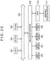
- FIG. 20 is a block diagram illustrating an example of a configuration of the hardware of the computer executing a series of processes described above by the program.
- a CPU Central Processing Unit
- ROM Read Only Memory
- RAM Random Access Memory
- An input/output interface 505 is also connected to the bus 504 .
- An input section 506 , an output section 507 , a recording section 508 , a communication section 509 , and a drive 510 are connected to the input/output interface 505 .
- the input section 506 includes a keyboard, a mouse, a microphone, an imaging element, and the like.
- the output section 507 includes a display, a loudspeaker, and the like.
- the recording section 508 includes a hard disk, a nonvolatile memory, and the like.
- the communication section 509 includes a network interface and the like.
- the drive 510 drives a removable recording medium 511 such as a magnetic disk, an optical disk, a magneto-optical disk or a semiconductor memory.
- the CPU 501 loads a program recorded in, for example, the recording section 508 to the RAM 503 via the input/output interface 505 and the bus 504 and executes the program, whereby a series of processes described above is performed.
- the program executed by the computer (CPU 501 ) can be provided by, for example, recording the program in the removable recording medium 511 serving as a package medium or the like.
- the program can be provided via a wired or wireless transmission medium such as a local area network, the Internet, or digital satellite broadcasting.
- the program can be installed into the recording section 508 via the input/output interface 505 by attaching the removable recording medium 511 to the drive 510 .
- the program can be received by the communication section 509 via the wired or wireless transmission medium and installed into the recording section 508 .
- the program can be installed into the ROM 502 or the recording section 508 in advance.
- the program executed by the computer may be a program for performing processes in time series in an order described in the present specification or may be a program for performing the processes either in parallel or at necessary timing such as timing of calling.
- the present technique can have a cloud computing configuration for causing a plurality of apparatuses to process one function in a sharing or cooperative fashion.
- each step described in the above flowcharts can be not only executed by one apparatus but also executed by a plurality of apparatuses in a sharing fashion.
- one step includes a plurality of processes
- the plurality of processes included in the one step can be not only executed by one apparatus but also executed by a plurality of apparatuses in a sharing fashion.
- the present technique can be configured as follows.
- An information processing apparatus including:
- an offset calculation section that calculates an offset amount of a position of a reference screen from a reference position present in a front direction of a user
- a position correction section that corrects a position of an audio object referred with the reference position, in conformity with the position of the reference screen on the basis of the offset amount
- a remapping section that remaps the position of the audio object in conformity with a position of a reproduction screen on the basis of the corrected position of the audio object.
- the offset calculation section corrects the offset amount by a predetermined correction value when the reference screen is placed in a backward direction of the user.
- the position correction section adjusts a correction value used during correction of the position of the audio object when a range of information that indicates the position of the audio object is specified as a range within a predetermined range.
- the position correction section corrects the position of the reference screen on the basis of the offset amount
- the remapping section remaps the position of the audio object on the basis of the corrected position of the reference screen and the corrected position of the audio object.
- An information processing method including the steps of:
- a program for causing a computer to execute a process including the steps of:
Abstract
Description
[Math. 6]
ϕoffset=ϕ−ϕoffset_value (6)
[Math. 13]
ϕoffset_left repro=ϕleft repro−ϕrepro_offset_value (13)
[Math. 14]
ϕoffset_right repro=ϕright repro−ϕrepro_offset_value (14)
[Math. 16]
ϕ″=ϕ′+ϕrepro_offset_value (16)
- 11: Information processing apparatus
- 21: Offset angle calculation section
- 22: Position information correction section
- 23: Object remapping section
Claims (3)
Priority Applications (1)
| Application Number | Priority Date | Filing Date | Title |
|---|---|---|---|
| US16/446,450 US10623884B2 (en) | 2015-07-16 | 2019-06-19 | Information processing apparatus, information processing method, and program |
Applications Claiming Priority (8)
| Application Number | Priority Date | Filing Date | Title |
|---|---|---|---|
| JP2015142253 | 2015-07-16 | ||
| JP2015-142253 | 2015-07-16 | ||
| JP2015-198582 | 2015-10-06 | ||
| JP2015198582 | 2015-10-06 | ||
| PCT/JP2016/069594 WO2017010313A1 (en) | 2015-07-16 | 2016-07-01 | Information processing apparatus and method, and program |
| US201815742944A | 2018-01-09 | 2018-01-09 | |
| US16/265,151 US10645523B2 (en) | 2015-07-16 | 2019-02-01 | Information processing apparatus, information processing method, and program |
| US16/446,450 US10623884B2 (en) | 2015-07-16 | 2019-06-19 | Information processing apparatus, information processing method, and program |
Related Parent Applications (1)
| Application Number | Title | Priority Date | Filing Date |
|---|---|---|---|
| US16/265,151 Continuation US10645523B2 (en) | 2015-07-16 | 2019-02-01 | Information processing apparatus, information processing method, and program |
Publications (2)
| Publication Number | Publication Date |
|---|---|
| US20190306653A1 US20190306653A1 (en) | 2019-10-03 |
| US10623884B2 true US10623884B2 (en) | 2020-04-14 |
Family
ID=57757900
Family Applications (3)
| Application Number | Title | Priority Date | Filing Date |
|---|---|---|---|
| US15/742,944 Active US10356547B2 (en) | 2015-07-16 | 2016-07-01 | Information processing apparatus, information processing method, and program |
| US16/265,151 Active US10645523B2 (en) | 2015-07-16 | 2019-02-01 | Information processing apparatus, information processing method, and program |
| US16/446,450 Active US10623884B2 (en) | 2015-07-16 | 2019-06-19 | Information processing apparatus, information processing method, and program |
Family Applications Before (2)
| Application Number | Title | Priority Date | Filing Date |
|---|---|---|---|
| US15/742,944 Active US10356547B2 (en) | 2015-07-16 | 2016-07-01 | Information processing apparatus, information processing method, and program |
| US16/265,151 Active US10645523B2 (en) | 2015-07-16 | 2019-02-01 | Information processing apparatus, information processing method, and program |
Country Status (12)
| Country | Link |
|---|---|
| US (3) | US10356547B2 (en) |
| EP (3) | EP3324653B1 (en) |
| JP (3) | JP6729585B2 (en) |
| KR (3) | KR20230080512A (en) |
| CN (4) | CN113055802B (en) |
| AU (2) | AU2016292271A1 (en) |
| BR (1) | BR112018000489B1 (en) |
| MY (1) | MY198158A (en) |
| RU (1) | RU2721750C2 (en) |
| SG (1) | SG11201710889UA (en) |
| TW (1) | TWI618395B (en) |
| WO (1) | WO2017010313A1 (en) |
Families Citing this family (4)
| Publication number | Priority date | Publication date | Assignee | Title |
|---|---|---|---|---|
| RU2721750C2 (en) * | 2015-07-16 | 2020-05-21 | Сони Корпорейшн | Information processing device, information processing method and program |
| CN113439099B (en) * | 2019-02-08 | 2022-12-09 | 三菱瓦斯化学株式会社 | Polycarbonate resin composition and optical lens using same |
| AU2020420226A1 (en) * | 2020-01-09 | 2022-06-02 | Sony Group Corporation | Information processing device and method, and program |
| GB2592610A (en) * | 2020-03-03 | 2021-09-08 | Nokia Technologies Oy | Apparatus, methods and computer programs for enabling reproduction of spatial audio signals |
Citations (11)
| Publication number | Priority date | Publication date | Assignee | Title |
|---|---|---|---|---|
| CN1717955A (en) | 2002-12-02 | 2006-01-04 | 汤姆森许可贸易公司 | Method for describing the composition of audio signals |
| CN102075832A (en) | 2009-11-24 | 2011-05-25 | 夏普株式会社 | Method and apparatus for dynamic spatial audio zones configuration |
| US20110123055A1 (en) | 2009-11-24 | 2011-05-26 | Sharp Laboratories Of America, Inc. | Multi-channel on-display spatial audio system |
| CN102421054A (en) | 2010-09-27 | 2012-04-18 | 夏普株式会社 | Spatial audio frequency configuration method and device of multichannel display |
| US20130236039A1 (en) | 2012-03-06 | 2013-09-12 | Thomson Licensing | Method and apparatus for playback of a higher-order ambisonics audio signal |
| WO2014035903A1 (en) | 2012-08-31 | 2014-03-06 | Dolby Laboratories Licensing Corporation | Bi-directional interconnect for communication between a renderer and an array of individually addressable drivers |
| CN103650535A (en) | 2011-07-01 | 2014-03-19 | 杜比实验室特许公司 | System and tools for enhanced 3D audio authoring and rendering |
| WO2014175668A1 (en) | 2013-04-27 | 2014-10-30 | 인텔렉추얼디스커버리 주식회사 | Audio signal processing method |
| US20160205492A1 (en) | 2013-08-21 | 2016-07-14 | Thomson Licensing | Video display having audio controlled by viewing direction |
| US20170011751A1 (en) | 2014-03-26 | 2017-01-12 | Fraunhofer-Gesellschaft Zur Foerderung Der Angewandten Forschung E.V. | Apparatus and method for screen related audio object remapping |
| US20180234786A1 (en) | 2015-07-16 | 2018-08-16 | Sony Corporation | Information processing apparatus, information processing method, and program |
Family Cites Families (14)
| Publication number | Priority date | Publication date | Assignee | Title |
|---|---|---|---|---|
| JP2002171460A (en) * | 2000-11-30 | 2002-06-14 | Sony Corp | Reproducing device |
| JP2006292900A (en) * | 2005-04-08 | 2006-10-26 | Hitachi Ltd | Projection optical unit and projection type image display apparatus using the same |
| US20070035560A1 (en) * | 2005-08-05 | 2007-02-15 | Samsung Electronics Co., Ltd. | Apparatus for providing multiple screens and method of dynamically configuring multiple screens |
| US8487956B2 (en) * | 2005-11-29 | 2013-07-16 | Kyocera Corporation | Communication terminal, system and display method to adaptively update a displayed image |
| KR100833241B1 (en) * | 2006-04-28 | 2008-05-28 | 삼성전자주식회사 | Sliding-tilt unit and mobile appliance adopting the same |
| CN103400583B (en) * | 2006-10-16 | 2016-01-20 | 杜比国际公司 | Enhancing coding and the Parametric Representation of object coding is mixed under multichannel |
| JP5455420B2 (en) * | 2009-04-22 | 2014-03-26 | キヤノン株式会社 | Video / audio playback apparatus and video / audio playback method |
| US9197736B2 (en) * | 2009-12-31 | 2015-11-24 | Digimarc Corporation | Intuitive computing methods and systems |
| GB2477793A (en) * | 2010-02-15 | 2011-08-17 | Sony Corp | A method of creating a stereoscopic image in a client device |
| JP5387478B2 (en) * | 2010-03-29 | 2014-01-15 | ソニー株式会社 | Audio reproduction apparatus and audio reproduction method |
| JP5893129B2 (en) * | 2011-04-18 | 2016-03-23 | ドルビー ラボラトリーズ ライセンシング コーポレイション | Method and system for generating 3D audio by upmixing audio |
| EP2733964A1 (en) * | 2012-11-15 | 2014-05-21 | Fraunhofer-Gesellschaft zur Förderung der angewandten Forschung e.V. | Segment-wise adjustment of spatial audio signal to different playback loudspeaker setup |
| US9264797B2 (en) * | 2012-12-21 | 2016-02-16 | Panasonic Intellectual Property Management Co., Ltd. | Directional microphone device, acoustic signal processing method, and program |
| JP6299124B2 (en) * | 2013-09-13 | 2018-03-28 | 株式会社リコー | Projection system, image processing apparatus, projection method, and program |
-
2016
- 2016-07-01 RU RU2018100009A patent/RU2721750C2/en active
- 2016-07-01 JP JP2017528385A patent/JP6729585B2/en active Active
- 2016-07-01 KR KR1020237018363A patent/KR20230080512A/en not_active Application Discontinuation
- 2016-07-01 US US15/742,944 patent/US10356547B2/en active Active
- 2016-07-01 AU AU2016292271A patent/AU2016292271A1/en not_active Abandoned
- 2016-07-01 CN CN202110310766.XA patent/CN113055802B/en active Active
- 2016-07-01 CN CN202110310767.4A patent/CN113055803B/en active Active
- 2016-07-01 EP EP16824293.1A patent/EP3324653B1/en active Active
- 2016-07-01 EP EP23152987.6A patent/EP4207756A1/en active Pending
- 2016-07-01 WO PCT/JP2016/069594 patent/WO2017010313A1/en active Application Filing
- 2016-07-01 CN CN201680040576.8A patent/CN107852561B/en active Active
- 2016-07-01 SG SG11201710889UA patent/SG11201710889UA/en unknown
- 2016-07-01 BR BR112018000489-8A patent/BR112018000489B1/en active IP Right Grant
- 2016-07-01 KR KR1020187027083A patent/KR102539973B1/en active IP Right Grant
- 2016-07-01 MY MYPI2018700101A patent/MY198158A/en unknown
- 2016-07-01 CN CN202110310465.7A patent/CN113055801B/en active Active
- 2016-07-01 EP EP20150228.3A patent/EP3668122B1/en active Active
- 2016-07-01 KR KR1020187000727A patent/KR101902158B1/en active IP Right Grant
- 2016-07-07 TW TW105121562A patent/TWI618395B/en active
-
2019
- 2019-02-01 US US16/265,151 patent/US10645523B2/en active Active
- 2019-06-19 US US16/446,450 patent/US10623884B2/en active Active
- 2019-06-26 AU AU2019204504A patent/AU2019204504B2/en active Active
-
2020
- 2020-07-01 JP JP2020114350A patent/JP6904466B2/en active Active
-
2021
- 2021-06-24 JP JP2021104858A patent/JP7136283B2/en active Active
Patent Citations (21)
| Publication number | Priority date | Publication date | Assignee | Title |
|---|---|---|---|---|
| PT1568251E (en) | 2002-12-02 | 2007-04-30 | Thomson Licensing | Method for describing the composition of audio signals |
| CN1717955A (en) | 2002-12-02 | 2006-01-04 | 汤姆森许可贸易公司 | Method for describing the composition of audio signals |
| CN102075832A (en) | 2009-11-24 | 2011-05-25 | 夏普株式会社 | Method and apparatus for dynamic spatial audio zones configuration |
| US20110123055A1 (en) | 2009-11-24 | 2011-05-26 | Sharp Laboratories Of America, Inc. | Multi-channel on-display spatial audio system |
| CN102421054A (en) | 2010-09-27 | 2012-04-18 | 夏普株式会社 | Spatial audio frequency configuration method and device of multichannel display |
| CN103650535A (en) | 2011-07-01 | 2014-03-19 | 杜比实验室特许公司 | System and tools for enhanced 3D audio authoring and rendering |
| US20130236039A1 (en) | 2012-03-06 | 2013-09-12 | Thomson Licensing | Method and apparatus for playback of a higher-order ambisonics audio signal |
| KR20130102015A (en) | 2012-03-06 | 2013-09-16 | 톰슨 라이센싱 | Method and apparatus for playback of a higher-order ambisonics audio signal |
| JP2013187908A (en) | 2012-03-06 | 2013-09-19 | Thomson Licensing | Method and apparatus for playback of high-order ambisonics audio signal |
| CN103313182A (en) | 2012-03-06 | 2013-09-18 | 汤姆逊许可公司 | Method and apparatus for playback of a higher-order ambisonics audio signal |
| US20150208190A1 (en) | 2012-08-31 | 2015-07-23 | Dolby Laboratories Licensing Corporation | Bi-directional interconnect for communication between a renderer and an array of individually addressable drivers |
| CN104604258A (en) | 2012-08-31 | 2015-05-06 | 杜比实验室特许公司 | Bi-directional interconnect for communication between a renderer and an array of individually addressable drivers |
| WO2014035903A1 (en) | 2012-08-31 | 2014-03-06 | Dolby Laboratories Licensing Corporation | Bi-directional interconnect for communication between a renderer and an array of individually addressable drivers |
| WO2014175668A1 (en) | 2013-04-27 | 2014-10-30 | 인텔렉추얼디스커버리 주식회사 | Audio signal processing method |
| US20160080884A1 (en) | 2013-04-27 | 2016-03-17 | Intellectual Discovery Co., Ltd. | Audio signal processing method |
| US20180048977A1 (en) | 2013-04-27 | 2018-02-15 | Intellectual Discovery Co., Ltd. | Audio signal processing method |
| US20160205492A1 (en) | 2013-08-21 | 2016-07-14 | Thomson Licensing | Video display having audio controlled by viewing direction |
| US20170011751A1 (en) | 2014-03-26 | 2017-01-12 | Fraunhofer-Gesellschaft Zur Foerderung Der Angewandten Forschung E.V. | Apparatus and method for screen related audio object remapping |
| US20180234786A1 (en) | 2015-07-16 | 2018-08-16 | Sony Corporation | Information processing apparatus, information processing method, and program |
| US20190166449A1 (en) | 2015-07-16 | 2019-05-30 | Sony Corporation | Information processing apparatus, information processing method, and program |
| US10356547B2 (en) * | 2015-07-16 | 2019-07-16 | Sony Corporation | Information processing apparatus, information processing method, and program |
Non-Patent Citations (13)
| Title |
|---|
| Chinese Office Action dated Oct. 28, 2019 in connection with Chinese Application No. 201680040576.8 and English translation thereof. |
| European Search Report dated Feb. 12, 2019 in connection with European Application No. 16824293.1. |
| Extended European Search Report dated Feb. 26, 2020 in connection with European Application No. 20150228.3. |
| Füg et al., Local Screen Information Interface and Screen-Related Object Remapping, International Organization for Standardization, MPEG Meeting Jul. 7, 2014-Jul. 11, 2014, Sapporo, ISO/IEC/JTC1/SC29/WG11, No. M34296, Jul. 3, 2014, 9 pages. |
| International Preliminary Report on Patentability and English translation thereof dated Jan. 25, 2018 in connection with International Application No. PCT/JP2016/069594. |
| International Search Report and English translation thereof dated Sep. 27, 2016 in connection with International Application No. PCT/JP2016/069594. |
| Korean Office Action in connection with Korean Application No. 10-2018-7000727 dated Mar. 20, 2018 and English translation thereof. |
| No Author Listed, Information technology-High efficiency coding and media delivery in heterogeneous environments-Part 3: 3D audio, Draft International Standard ISO/IEC DIS 23008-3, ISO/IEC JTC 1/SC 29/WG 11, Jul. 25, 2014, 433 pages. |
| No Author Listed, Information technology—High efficiency coding and media delivery in heterogeneous environments—Part 3: 3D audio, Draft International Standard ISO/IEC DIS 23008-3, ISO/IEC JTC 1/SC 29/WG 11, Jul. 25, 2014, 433 pages. |
| No Author Listed, International Standard ISO/IEC 23008-3, Information technology-High efficiency coding and media delivery in heterogeneous environments-Part 3: 3D audio, First edition Oct. 15, 2015, corrected version Feb. 1, 2016, ISO/IEC 23008-3:2015(E), 439 pages. |
| No Author Listed, International Standard ISO/IEC 23008-3, Information technology—High efficiency coding and media delivery in heterogeneous environments—Part 3: 3D audio, First edition Oct. 15, 2015, corrected version Feb. 1, 2016, ISO/IEC 23008-3:2015(E), 439 pages. |
| Shi et al., Screen-Related Object Remapping for Zooming, International Organization for Standardization, MPEG Meeting Jul. 7, 2014-Jul. 11, 2014, Sapporo, ISO/IEC/JTC1/SC29/WG11, No. M34253, Jul. 3, 2014, 12 pages. |
| Written Opinion and English translation thereof dated Sep. 27, 2016 in connection with International Application No. PCT/JP2016/069594. |
Also Published As
Similar Documents
| Publication | Publication Date | Title |
|---|---|---|
| US10623884B2 (en) | Information processing apparatus, information processing method, and program | |
| US20180040112A1 (en) | Perspective correction for curved display screens | |
| US10708707B2 (en) | Audio processing apparatus and method and program | |
| JP7388492B2 (en) | Signal processing device and method, and program | |
| US10595148B2 (en) | Sound processing apparatus and method, and program | |
| US10972859B2 (en) | Signal processing apparatus and method as well as program | |
| US20210144504A1 (en) | Signal processing device and method, and program | |
| CN116709033A (en) | Panoramic video recording method, device, equipment and storage medium |
Legal Events
| Date | Code | Title | Description |
|---|---|---|---|
| FEPP | Fee payment procedure |
Free format text: ENTITY STATUS SET TO UNDISCOUNTED (ORIGINAL EVENT CODE: BIG.); ENTITY STATUS OF PATENT OWNER: LARGE ENTITY |
|
| STPP | Information on status: patent application and granting procedure in general |
Free format text: NON FINAL ACTION MAILED |
|
| AS | Assignment |
Owner name: SONY CORPORATION, JAPAN Free format text: ASSIGNMENT OF ASSIGNORS INTEREST;ASSIGNORS:TSUJI, MINORU;CHINEN, TORU;REEL/FRAME:049944/0536 Effective date: 20171212 |
|
| STPP | Information on status: patent application and granting procedure in general |
Free format text: RESPONSE TO NON-FINAL OFFICE ACTION ENTERED AND FORWARDED TO EXAMINER |
|
| STPP | Information on status: patent application and granting procedure in general |
Free format text: NOTICE OF ALLOWANCE MAILED -- APPLICATION RECEIVED IN OFFICE OF PUBLICATIONS |
|
| STPP | Information on status: patent application and granting procedure in general |
Free format text: PUBLICATIONS -- ISSUE FEE PAYMENT RECEIVED |
|
| STCF | Information on status: patent grant |
Free format text: PATENTED CASE |
|
| CC | Certificate of correction | ||
| MAFP | Maintenance fee payment |
Free format text: PAYMENT OF MAINTENANCE FEE, 4TH YEAR, LARGE ENTITY (ORIGINAL EVENT CODE: M1551); ENTITY STATUS OF PATENT OWNER: LARGE ENTITY Year of fee payment: 4 |