US10622645B2 - Assembly system that assembles insulating plate and mounting bar, and assembly method - Google Patents
Assembly system that assembles insulating plate and mounting bar, and assembly method Download PDFInfo
- Publication number
- US10622645B2 US10622645B2 US15/662,191 US201715662191A US10622645B2 US 10622645 B2 US10622645 B2 US 10622645B2 US 201715662191 A US201715662191 A US 201715662191A US 10622645 B2 US10622645 B2 US 10622645B2
- Authority
- US
- United States
- Prior art keywords
- stack
- mounting
- arm
- transferring
- insulation
- Prior art date
- Legal status (The legal status is an assumption and is not a legal conclusion. Google has not performed a legal analysis and makes no representation as to the accuracy of the status listed.)
- Active, expires
Links
- 238000000034 method Methods 0.000 title description 18
- 238000009413 insulation Methods 0.000 claims abstract description 144
- 238000001179 sorption measurement Methods 0.000 claims description 31
- 238000012546 transfer Methods 0.000 claims description 8
- 239000000446 fuel Substances 0.000 description 10
- 238000003487 electrochemical reaction Methods 0.000 description 3
- 238000012986 modification Methods 0.000 description 3
- 230000004048 modification Effects 0.000 description 3
- UFHFLCQGNIYNRP-UHFFFAOYSA-N Hydrogen Chemical compound [H][H] UFHFLCQGNIYNRP-UHFFFAOYSA-N 0.000 description 2
- QVGXLLKOCUKJST-UHFFFAOYSA-N atomic oxygen Chemical compound [O] QVGXLLKOCUKJST-UHFFFAOYSA-N 0.000 description 2
- 230000008901 benefit Effects 0.000 description 2
- 230000005611 electricity Effects 0.000 description 2
- 239000003792 electrolyte Substances 0.000 description 2
- 239000001257 hydrogen Substances 0.000 description 2
- 229910052739 hydrogen Inorganic materials 0.000 description 2
- 239000001301 oxygen Substances 0.000 description 2
- 229910052760 oxygen Inorganic materials 0.000 description 2
- 239000005518 polymer electrolyte Substances 0.000 description 2
- 241000490025 Schefflera digitata Species 0.000 description 1
- 238000002485 combustion reaction Methods 0.000 description 1
- 238000010276 construction Methods 0.000 description 1
- 230000007797 corrosion Effects 0.000 description 1
- 238000005260 corrosion Methods 0.000 description 1
- 238000013461 design Methods 0.000 description 1
- 230000006866 deterioration Effects 0.000 description 1
- 238000005516 engineering process Methods 0.000 description 1
- 239000002737 fuel gas Substances 0.000 description 1
- 235000015250 liver sausages Nutrition 0.000 description 1
- 239000012528 membrane Substances 0.000 description 1
- 238000011160 research Methods 0.000 description 1
Images


Classifications
-
- H—ELECTRICITY
- H01—ELECTRIC ELEMENTS
- H01M—PROCESSES OR MEANS, e.g. BATTERIES, FOR THE DIRECT CONVERSION OF CHEMICAL ENERGY INTO ELECTRICAL ENERGY
- H01M8/00—Fuel cells; Manufacture thereof
- H01M8/02—Details
- H01M8/0297—Arrangements for joining electrodes, reservoir layers, heat exchange units or bipolar separators to each other
-
- B—PERFORMING OPERATIONS; TRANSPORTING
- B60—VEHICLES IN GENERAL
- B60L—PROPULSION OF ELECTRICALLY-PROPELLED VEHICLES; SUPPLYING ELECTRIC POWER FOR AUXILIARY EQUIPMENT OF ELECTRICALLY-PROPELLED VEHICLES; ELECTRODYNAMIC BRAKE SYSTEMS FOR VEHICLES IN GENERAL; MAGNETIC SUSPENSION OR LEVITATION FOR VEHICLES; MONITORING OPERATING VARIABLES OF ELECTRICALLY-PROPELLED VEHICLES; ELECTRIC SAFETY DEVICES FOR ELECTRICALLY-PROPELLED VEHICLES
- B60L50/00—Electric propulsion with power supplied within the vehicle
- B60L50/50—Electric propulsion with power supplied within the vehicle using propulsion power supplied by batteries or fuel cells
- B60L50/70—Electric propulsion with power supplied within the vehicle using propulsion power supplied by batteries or fuel cells using power supplied by fuel cells
- B60L50/72—Constructional details of fuel cells specially adapted for electric vehicles
-
- B—PERFORMING OPERATIONS; TRANSPORTING
- B60—VEHICLES IN GENERAL
- B60L—PROPULSION OF ELECTRICALLY-PROPELLED VEHICLES; SUPPLYING ELECTRIC POWER FOR AUXILIARY EQUIPMENT OF ELECTRICALLY-PROPELLED VEHICLES; ELECTRODYNAMIC BRAKE SYSTEMS FOR VEHICLES IN GENERAL; MAGNETIC SUSPENSION OR LEVITATION FOR VEHICLES; MONITORING OPERATING VARIABLES OF ELECTRICALLY-PROPELLED VEHICLES; ELECTRIC SAFETY DEVICES FOR ELECTRICALLY-PROPELLED VEHICLES
- B60L53/00—Methods of charging batteries, specially adapted for electric vehicles; Charging stations or on-board charging equipment therefor; Exchange of energy storage elements in electric vehicles
- B60L53/50—Charging stations characterised by energy-storage or power-generation means
- B60L53/54—Fuel cells
-
- H—ELECTRICITY
- H01—ELECTRIC ELEMENTS
- H01M—PROCESSES OR MEANS, e.g. BATTERIES, FOR THE DIRECT CONVERSION OF CHEMICAL ENERGY INTO ELECTRICAL ENERGY
- H01M8/00—Fuel cells; Manufacture thereof
- H01M8/24—Grouping of fuel cells, e.g. stacking of fuel cells
- H01M8/2404—Processes or apparatus for grouping fuel cells
-
- H—ELECTRICITY
- H01—ELECTRIC ELEMENTS
- H01M—PROCESSES OR MEANS, e.g. BATTERIES, FOR THE DIRECT CONVERSION OF CHEMICAL ENERGY INTO ELECTRICAL ENERGY
- H01M8/00—Fuel cells; Manufacture thereof
- H01M8/24—Grouping of fuel cells, e.g. stacking of fuel cells
- H01M8/241—Grouping of fuel cells, e.g. stacking of fuel cells with solid or matrix-supported electrolytes
-
- H—ELECTRICITY
- H01—ELECTRIC ELEMENTS
- H01M—PROCESSES OR MEANS, e.g. BATTERIES, FOR THE DIRECT CONVERSION OF CHEMICAL ENERGY INTO ELECTRICAL ENERGY
- H01M8/00—Fuel cells; Manufacture thereof
- H01M8/24—Grouping of fuel cells, e.g. stacking of fuel cells
- H01M8/2465—Details of groupings of fuel cells
- H01M8/247—Arrangements for tightening a stack, for accommodation of a stack in a tank or for assembling different tanks
- H01M8/2475—Enclosures, casings or containers of fuel cell stacks
-
- H—ELECTRICITY
- H01—ELECTRIC ELEMENTS
- H01M—PROCESSES OR MEANS, e.g. BATTERIES, FOR THE DIRECT CONVERSION OF CHEMICAL ENERGY INTO ELECTRICAL ENERGY
- H01M8/00—Fuel cells; Manufacture thereof
- H01M8/24—Grouping of fuel cells, e.g. stacking of fuel cells
- H01M8/2465—Details of groupings of fuel cells
- H01M8/247—Arrangements for tightening a stack, for accommodation of a stack in a tank or for assembling different tanks
- H01M8/248—Means for compression of the fuel cell stacks
-
- B—PERFORMING OPERATIONS; TRANSPORTING
- B23—MACHINE TOOLS; METAL-WORKING NOT OTHERWISE PROVIDED FOR
- B23P—METAL-WORKING NOT OTHERWISE PROVIDED FOR; COMBINED OPERATIONS; UNIVERSAL MACHINE TOOLS
- B23P19/00—Machines for simply fitting together or separating metal parts or objects, or metal and non-metal parts, whether or not involving some deformation; Tools or devices therefor so far as not provided for in other classes
- B23P19/001—Article feeders for assembling machines
-
- B—PERFORMING OPERATIONS; TRANSPORTING
- B23—MACHINE TOOLS; METAL-WORKING NOT OTHERWISE PROVIDED FOR
- B23P—METAL-WORKING NOT OTHERWISE PROVIDED FOR; COMBINED OPERATIONS; UNIVERSAL MACHINE TOOLS
- B23P19/00—Machines for simply fitting together or separating metal parts or objects, or metal and non-metal parts, whether or not involving some deformation; Tools or devices therefor so far as not provided for in other classes
- B23P19/008—Machines for simply fitting together or separating metal parts or objects, or metal and non-metal parts, whether or not involving some deformation; Tools or devices therefor so far as not provided for in other classes the parts being continuously transported through the machine during assembling or disassembling
-
- B—PERFORMING OPERATIONS; TRANSPORTING
- B23—MACHINE TOOLS; METAL-WORKING NOT OTHERWISE PROVIDED FOR
- B23P—METAL-WORKING NOT OTHERWISE PROVIDED FOR; COMBINED OPERATIONS; UNIVERSAL MACHINE TOOLS
- B23P21/00—Machines for assembling a multiplicity of different parts to compose units, with or without preceding or subsequent working of such parts, e.g. with programme control
- B23P21/002—Machines for assembling a multiplicity of different parts to compose units, with or without preceding or subsequent working of such parts, e.g. with programme control the units stationary whilst being composed
-
- B—PERFORMING OPERATIONS; TRANSPORTING
- B23—MACHINE TOOLS; METAL-WORKING NOT OTHERWISE PROVIDED FOR
- B23P—METAL-WORKING NOT OTHERWISE PROVIDED FOR; COMBINED OPERATIONS; UNIVERSAL MACHINE TOOLS
- B23P21/00—Machines for assembling a multiplicity of different parts to compose units, with or without preceding or subsequent working of such parts, e.g. with programme control
- B23P21/008—Machines for assembling a multiplicity of different parts to compose units, with or without preceding or subsequent working of such parts, e.g. with programme control the assembling machines or tools moving synchronously with the units while these are being assembled
-
- H—ELECTRICITY
- H01—ELECTRIC ELEMENTS
- H01M—PROCESSES OR MEANS, e.g. BATTERIES, FOR THE DIRECT CONVERSION OF CHEMICAL ENERGY INTO ELECTRICAL ENERGY
- H01M10/00—Secondary cells; Manufacture thereof
- H01M10/04—Construction or manufacture in general
- H01M10/0404—Machines for assembling batteries
-
- H—ELECTRICITY
- H01—ELECTRIC ELEMENTS
- H01M—PROCESSES OR MEANS, e.g. BATTERIES, FOR THE DIRECT CONVERSION OF CHEMICAL ENERGY INTO ELECTRICAL ENERGY
- H01M8/00—Fuel cells; Manufacture thereof
- H01M8/10—Fuel cells with solid electrolytes
- H01M2008/1095—Fuel cells with polymeric electrolytes
-
- H—ELECTRICITY
- H01—ELECTRIC ELEMENTS
- H01M—PROCESSES OR MEANS, e.g. BATTERIES, FOR THE DIRECT CONVERSION OF CHEMICAL ENERGY INTO ELECTRICAL ENERGY
- H01M2250/00—Fuel cells for particular applications; Specific features of fuel cell system
- H01M2250/20—Fuel cells in motive systems, e.g. vehicle, ship, plane
-
- Y—GENERAL TAGGING OF NEW TECHNOLOGICAL DEVELOPMENTS; GENERAL TAGGING OF CROSS-SECTIONAL TECHNOLOGIES SPANNING OVER SEVERAL SECTIONS OF THE IPC; TECHNICAL SUBJECTS COVERED BY FORMER USPC CROSS-REFERENCE ART COLLECTIONS [XRACs] AND DIGESTS
- Y02—TECHNOLOGIES OR APPLICATIONS FOR MITIGATION OR ADAPTATION AGAINST CLIMATE CHANGE
- Y02E—REDUCTION OF GREENHOUSE GAS [GHG] EMISSIONS, RELATED TO ENERGY GENERATION, TRANSMISSION OR DISTRIBUTION
- Y02E60/00—Enabling technologies; Technologies with a potential or indirect contribution to GHG emissions mitigation
- Y02E60/30—Hydrogen technology
- Y02E60/50—Fuel cells
-
- Y—GENERAL TAGGING OF NEW TECHNOLOGICAL DEVELOPMENTS; GENERAL TAGGING OF CROSS-SECTIONAL TECHNOLOGIES SPANNING OVER SEVERAL SECTIONS OF THE IPC; TECHNICAL SUBJECTS COVERED BY FORMER USPC CROSS-REFERENCE ART COLLECTIONS [XRACs] AND DIGESTS
- Y02—TECHNOLOGIES OR APPLICATIONS FOR MITIGATION OR ADAPTATION AGAINST CLIMATE CHANGE
- Y02P—CLIMATE CHANGE MITIGATION TECHNOLOGIES IN THE PRODUCTION OR PROCESSING OF GOODS
- Y02P70/00—Climate change mitigation technologies in the production process for final industrial or consumer products
- Y02P70/50—Manufacturing or production processes characterised by the final manufactured product
-
- Y—GENERAL TAGGING OF NEW TECHNOLOGICAL DEVELOPMENTS; GENERAL TAGGING OF CROSS-SECTIONAL TECHNOLOGIES SPANNING OVER SEVERAL SECTIONS OF THE IPC; TECHNICAL SUBJECTS COVERED BY FORMER USPC CROSS-REFERENCE ART COLLECTIONS [XRACs] AND DIGESTS
- Y02—TECHNOLOGIES OR APPLICATIONS FOR MITIGATION OR ADAPTATION AGAINST CLIMATE CHANGE
- Y02T—CLIMATE CHANGE MITIGATION TECHNOLOGIES RELATED TO TRANSPORTATION
- Y02T10/00—Road transport of goods or passengers
- Y02T10/60—Other road transportation technologies with climate change mitigation effect
- Y02T10/70—Energy storage systems for electromobility, e.g. batteries
-
- Y—GENERAL TAGGING OF NEW TECHNOLOGICAL DEVELOPMENTS; GENERAL TAGGING OF CROSS-SECTIONAL TECHNOLOGIES SPANNING OVER SEVERAL SECTIONS OF THE IPC; TECHNICAL SUBJECTS COVERED BY FORMER USPC CROSS-REFERENCE ART COLLECTIONS [XRACs] AND DIGESTS
- Y02—TECHNOLOGIES OR APPLICATIONS FOR MITIGATION OR ADAPTATION AGAINST CLIMATE CHANGE
- Y02T—CLIMATE CHANGE MITIGATION TECHNOLOGIES RELATED TO TRANSPORTATION
- Y02T10/00—Road transport of goods or passengers
- Y02T10/60—Other road transportation technologies with climate change mitigation effect
- Y02T10/7072—Electromobility specific charging systems or methods for batteries, ultracapacitors, supercapacitors or double-layer capacitors
-
- Y—GENERAL TAGGING OF NEW TECHNOLOGICAL DEVELOPMENTS; GENERAL TAGGING OF CROSS-SECTIONAL TECHNOLOGIES SPANNING OVER SEVERAL SECTIONS OF THE IPC; TECHNICAL SUBJECTS COVERED BY FORMER USPC CROSS-REFERENCE ART COLLECTIONS [XRACs] AND DIGESTS
- Y02—TECHNOLOGIES OR APPLICATIONS FOR MITIGATION OR ADAPTATION AGAINST CLIMATE CHANGE
- Y02T—CLIMATE CHANGE MITIGATION TECHNOLOGIES RELATED TO TRANSPORTATION
- Y02T90/00—Enabling technologies or technologies with a potential or indirect contribution to GHG emissions mitigation
- Y02T90/10—Technologies relating to charging of electric vehicles
- Y02T90/12—Electric charging stations
-
- Y02T90/32—
-
- Y—GENERAL TAGGING OF NEW TECHNOLOGICAL DEVELOPMENTS; GENERAL TAGGING OF CROSS-SECTIONAL TECHNOLOGIES SPANNING OVER SEVERAL SECTIONS OF THE IPC; TECHNICAL SUBJECTS COVERED BY FORMER USPC CROSS-REFERENCE ART COLLECTIONS [XRACs] AND DIGESTS
- Y02—TECHNOLOGIES OR APPLICATIONS FOR MITIGATION OR ADAPTATION AGAINST CLIMATE CHANGE
- Y02T—CLIMATE CHANGE MITIGATION TECHNOLOGIES RELATED TO TRANSPORTATION
- Y02T90/00—Enabling technologies or technologies with a potential or indirect contribution to GHG emissions mitigation
- Y02T90/40—Application of hydrogen technology to transportation, e.g. using fuel cells
-
- Y—GENERAL TAGGING OF NEW TECHNOLOGICAL DEVELOPMENTS; GENERAL TAGGING OF CROSS-SECTIONAL TECHNOLOGIES SPANNING OVER SEVERAL SECTIONS OF THE IPC; TECHNICAL SUBJECTS COVERED BY FORMER USPC CROSS-REFERENCE ART COLLECTIONS [XRACs] AND DIGESTS
- Y10—TECHNICAL SUBJECTS COVERED BY FORMER USPC
- Y10S—TECHNICAL SUBJECTS COVERED BY FORMER USPC CROSS-REFERENCE ART COLLECTIONS [XRACs] AND DIGESTS
- Y10S903/00—Hybrid electric vehicles, HEVS
- Y10S903/902—Prime movers comprising electrical and internal combustion motors
- Y10S903/903—Prime movers comprising electrical and internal combustion motors having energy storing means, e.g. battery, capacitor
- Y10S903/904—Component specially adapted for hev
- Y10S903/908—Fuel cell
Definitions
- the present invention relates to an assembly system that assembles an insulation plate and a mounting bar to a stack that is pressed by a pressing device, and an assembly method.
- a fuel cell vehicle uses electricity generated from an electrochemical reaction between hydrogen and oxygen as an energy source.
- the fuel cell vehicle is driven by use of electrical energy generated from an electrochemical reaction between supplied hydrogen and oxygen in the air in a fuel cell stack.
- the fuel cell system directly converts energy of fuel into electrical energy, and an anode and a cathode, which are provided as a pair, are disposed interposing an electrolyte therebetween, and electricity and heat are produced together through an electrochemical reaction of an ionized fuel gas.
- a polymer electrolyte fuel cell With merits of a high current density, a low driving temperature, less corrosion, and less electrolyte loss, a polymer electrolyte fuel cell has been developed for military purpose or as a spacecraft power source, and recently, researches are underway to apply a polymer electrolyte fuel cell as a vehicle power source.
- a fuel cell stack of the fuel cell system is formed by stacking a membrane electrode assemble (MEA), a separator, and the like.
- MEA membrane electrode assemble
- the fuel cell stack is manufactured by sequentially stacking a plurality of parts, the parts may be misaligned or the stacking order of the parts may be disordered, thereby causing critical damage to product performance.
- stack cells of a small module unit are transferred to the assembly device and insulation plates and mounting bars are manually assembled by a worker, thereby resulting in a low automation ratio, low productivity, and poor assembly.
- Various aspects of the present invention are directed to providing an assembly system that discharges a stack from a stack pressing device that compresses a layered stack, assembles insulation plates and mounting bars to the discharged stack, and assembles insulation plates and mounting bars to the stack through automatically fastening bolts or nuts.
- An assembly system that assembles insulation plates and mounting bars to a stack may include a stack transferring device that discharges a stack pressed by a stack pressing device to the outside; an insulation plate attaching device that attaches insulation plates to opposite sides of the stack that is discharged to the outside by the stack transferring device; a mounting bar attaching device that attaches mounting bars to the stack to which the insulation plates are attached; and a bolt assembling device that assembles bolts to the mounting bars that are attached to the stack.
- the stack transferring device may include: a transferring rail; a transferring arm mounted to the transferring rail and having a mounting jig where the stack is mounted; and a mounting jig transferring device that transfers the transferring arm where the mounting jig is formed while moving along the transferring rail.
- the assembly system that assembles the insulation plates and the mounting bars to the stack may further include a rotation device that rotates the stack mounted to the transferring arm at a predetermined angle.
- the insulation plate attaching device may include: an insulation plate magazine where the insulation plates are loaded; insulation plate adsorption members that are set to adsorb the insulation plates loaded in the insulation plate magazine; an insulation plate mounting arm where the insulation plate adsorption members are disposed in lateral sides thereof; and insulation plate rotation devices that are set to rotate the insulation plate adsorption members.
- the assembly system that assembles the insulation plates and the mounting bars to the stack may further include: insulation plate transferring units that are provided in the insulation plate mounting arm to transfer the insulation plate adsorption members; an arm transferring device that transfers the insulation plate mounting arm along an arm transferring rail; and a vertical location adjusting device that is provided to connect the arm transferring rail and the insulation plate mounting arm and adjust a distance between the arm transferring rail and the insulation plate mounting arm.
- the mounting bar attaching device may include: a mounting bar magazine where the mounting bars are loaded; a mounting bar adsorption member that is provided to adsorb the mounting bars loaded in the mounting bar magazine; a mounting bar rotation device that is provided to rotate the mounting bar adsorption member; and a mounting bar transferring device that moves the mounting bar adsorption member in a vertical direction thereof and a horizontal direction thereof along a vertical rail or a horizontal rail.
- the bolt assembling device may include: a bolt feeder that feeds bolts to fix the mounting bars to the stack; a runner arm through which the bolt supplied from the bolt feeder is transferred; and a bolt runner that is provided at a front end portion of the runner arm and assembles the mounting bars to the stack by rotating the bolts transferred along the runner arm.
- the bolt assembling device may include a bolt runner transferring device that moves the runner arm in a vertical or horizontal direction.
- the bolt runner transferring device may move the runner arm along a horizontal rail and a vertical rail through which the runner arm moves in the horizontal direction and the vertical direction.
- the assembly system that assembles the insulation plates and the mounting bars to the stack may include a runner rotation device that provides a torque for the runner arm to rotate the bolt runner.
- the assembly system that assembles the insulation plates and the mounting bars to the stack may further include: clamps that temporarily fix the insulation plates to the stack while the insulation plates are attached to the stack; and clamping cylinders that are provided to move the clamps in a predetermined direction.
- a method for assembling insulation plates and mounting bars to a stack may include moving a stack pressed by a pressing device to the outside; attaching the insulation plates to the stack; attaching the mounting bars that fix the insulation plates to the stack; and assembling bolts to fix the mounting bars to the stack.
- the method for assembling the insulation plates and the mounting bars to the stack may further include moving the stack where the mounting bars and the insulation plates are attached to a post process.
- the method for assembling the insulation plates and the mounting bars to the stack may further include transferring bolts to a runner to tighten the bolts.
- one insulation plate may be attached to one side of the stack and another insulation plate may be attached to the other side of the stack.
- the method for assembling the insulation plates and the mounting bars to the stack may further include temporarily fixing the insulation plates to prevent the insulation plates from being detached.
- a runner may rotate the bolts at a predetermined location where the bolts are assembled.
- the mounting bars may be adsorbed from a magazine and moved to be attached to the stack.
- the stack can be automatically discharged from the stack pressing device, and the insulation plates can be attached to opposite sides of the stack and fixed to the stack stably by use of the mounting bars, preventing quality deterioration and occurrence of leakage.
- FIG. 1 is a perspective view of an assembly system that assembles an insulation plate and a mounting bar to a stack according to an exemplary embodiment of the present invention.
- FIG. 2 is a perspective view of a stack transferring device according to the exemplary embodiment of the present invention.
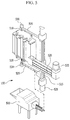
- FIG. 3 is a perspective view of an insulation plate attaching device according to the exemplary embodiment of the present invention.
- FIG. 4 is a perspective view of a mounting bar attaching device according to the exemplary embodiment of the present invention.
- FIG. 5 is a perspective view of a bolt assembling device according to the exemplary embodiment of the present invention.
- FIG. 6 is a perspective view of a method for the stack transferring device to discharge the stack according to the exemplary embodiment of the present invention.
- FIG. 7 is a side view of a structure for temporarily fixing the insulation plates to the stack and a structure for rotating the stack according to the exemplary embodiment of the present invention.
- FIG. 8 is a perspective view of an operation method of an insulation plate attaching device according to the exemplary embodiment of the present invention.
- FIG. 9 is a perspective view of an operation method of a mounting bar attaching device according to the exemplary embodiment of the present invention.
- FIG. 10 is a perspective view of the stack according to the exemplary embodiment of the present invention.
- FIG. 11 is a flowchart of a method for assembling the insulation plates and the mounting bars to the stack according to the exemplary embodiment of the present invention.
- FIG. 1 is a perspective view of an assembly system that assembles an insulation plate and a mounting bar to a stack according to an exemplary embodiment of the present invention.
- an assembly system includes a stack pressing device 100 , a stack transferring device 120 , a bolt assembling device 130 , a mounting bar attaching device 140 , and an insulation plate attaching device 150 .
- the stack pressing device 100 presses the stack 110 and lifts the pressed stack 110 .
- the stack transferring device 120 is assembled to a lower portion of the stack 110 that is disposed in an upper portion of the stack pressing device 100 , and discharges the stack 110 to the outside from the stack pressing device 100 .
- the insulation plate attaching device 150 adsorbs insulation plates 145 located in an insulation plate magazine 300 from opposite sides to attach the insulation plates 145 to opposite sides of the stack 110
- the mounting bar attaching device 140 adsorbs mounting bars 135 located in a mounting bar magazine 400 to attach the adsorbed mounting bars 135 to respective sides of the stack 110 .
- the bolt assembling device 130 inserts bolts supplied from a bolt feeder 500 (refer to FIG. 5 ) to opposite end portions of the mounting bar 135 and rotates the bolts to fix the mounting bar 135 to the stack 110 .
- FIG. 2 is a perspective view of a stack transferring device according to the exemplary embodiment of the present invention.
- the transferring device 120 includes a transferring arm 200 , a transferring rail 205 , a mounting jig 215 , and a mounting jig transferring device 210 .
- the transferring arm 200 moves along the transferring rail 205 , and the transferring arm 200 may be inserted into the stack pressing device 100 or may move to the outside.
- the mounting jig 215 is provided in one upper side of the transferring arm 200 , and the stack 110 is mounted to the mounting jig 215 and then fixed thereto.
- the stack 110 disposed in the mounting jig 215 may be rotated by a rotation device 700 as shown in FIG. 7 .
- the mounting jig transferring device 210 may enable the transferring arm 200 to move along the transferring rail 205 by use of a step motor and the like.
- FIG. 6 is a perspective view of a method for the stack transferring device to discharge the stack according to the exemplary embodiment of the present invention.
- the transferring arm 200 moves into the stack pressing device 100 , and a lower portion of the stack 110 is assembled with the stack mounting jig 215 of the transferring arm 200 .
- the stack 110 is separated from the stack pressing device 100 , and the transferring arm 200 moves to discharge the stack 110 to the outside.
- a structure of the stack pressing device 100 is known technology and therefore the description thereof will be omitted.
- FIG. 3 is a perspective view of the insulation plate attaching device according to the exemplary embodiment of the present invention.
- the insulation plate attaching device 150 includes the insulation plate magazines 300 , an auto-lifting device 305 , an insulation plate adsorption member 310 , an insulation plate rotation device 315 , an insulation plate mounting arm 320 , an insulation plate transferring device 325 , a vertical location adjusting device 330 , an arm transferring rail 335 , and an arm transferring device 340 .
- the insulation plates 145 are loaded in the insulation plate magazines 300 , and the auto-lifting device 305 maintains a constant height of an upper surface of the insulation plate 145 according to a use amount.
- the insulation plate rotation device 315 is fixed to one side of the insulation plate mounting arm 320 while having a predetermined distance therebetween, and the insulation plate adsorption members 310 are provided in the insulation plate rotation devices 315 .
- the insulation plate adsorption members 310 disposed in lateral sides are parallel with each other.
- the insulation plate transferring units 325 are provided in the insulation plate mounting arm 320 to adjust a distance between the insulation plate adsorption members 310 .
- the arm transferring rail 335 is provided in an upper side of the insulation plate mounting arm 320 in a direction that is perpendicular to the insulation plate mounting arm 320 , and the vertical location adjusting device 330 connects the upper portion of the insulation plate mounting arm 320 and the arm transferring rail 335 .
- the vertical location adjusting device 330 is disposed to be movable along the arm transferring rail 335 , and the arm transferring device 340 can move the insulation plate mounting arm 320 by moving the vertical location adjusting device 330 along the arm transferring rail 335 .
- the vertical location adjusting device 330 may be telescopic to be adjustable in length like an antenna.
- FIG. 8 is a perspective view of an operation method of the insulation plate attaching device according to the exemplary embodiment of the present invention.
- the insulation plate adsorption member 310 descends by way of the insulation plate rotation device 315 while adsorption surfaces of the insulation plate adsorption members 310 adsorb the insulation plates 145 .
- the insulation plate adsorption members 310 attach the insulation plates 145 to the opposite sides of the stack 110 .
- FIG. 4 is a perspective view of the mounting bar attaching device according to the exemplary embodiment of the present invention.
- the mounting bar attaching device 140 includes the mounting bar magazine 400 , an auto-lifting device 405 , a mounting bar adsorption member 415 , a mounting bar rotation device 420 , a horizontal transferring rail 430 , a vertical transferring rail 425 , and a mounting bar transferring device 435 .
- the mounting bar 135 is loaded in the mounting bar magazine 400 , and the auto-lifting device 405 maintains a constant height of the mounting bar 135 .
- a structure for the mounting bar 135 to maintain the constant height will refer to prior arts.
- the mounting bar adsorption member 415 is disposed to adsorb a plurality of mounting bars 135 that are loaded in the mounting bar magazine 400 , for example, three mounting bars 135 , and the mounting bar rotation device 420 is disposed to rotate the mounting bar adsorption member 415 .
- the mounting bar rotation device 420 is disposed to be vertically movable in the vertical transferring rail 425 , and the mounting bar transferring device 435 provides a torque to vertically move the mounting bar rotation device 420 using a step motor and the like.
- the vertical transferring rail 425 is disposed to be horizontally movable in the horizontal transferring rail 430 .
- the mounting bar adsorption member 415 moves along the horizontal transferring rail 430 and the vertical transferring rail 425 and adsorbs the mounting bars 135 at a predetermined location by being rotated by the mounting bar rotation device 420 to attach the mounting bars 135 to one side of the stack 110 .
- FIG. 9 is a perspective view of an operation of the mounting bar attaching device according to the exemplary embodiment of the present invention.
- the mounting bar adsorption members 415 move above the mounting bar magazine 400 to adsorb the upper surfaces of the mounting bars 135 , and move and rotate to attach the mounting bars 135 to one side of the stack 110 .
- the stack 110 rotates 180 degrees by way of the rotation device 700 (refer to FIG. 7 ), and then the mounting bar adsorption members 415 attach the mounting bars 135 to the other side of the stack 110 .
- FIG. 5 is a perspective view of the bolt assembling device according to the exemplary embodiment of the present invention.
- the bolt assembling device 130 includes the bolt feeder 500 , a bolt runner 510 , a runner arm 505 , a vertical transferring rail 515 , a horizontal transferring rail 520 , a bolt runner transferring device 525 , and a bolt runner rotation device 530 .
- the bolt runner 510 is disposed at a front end portion of the runner arm 510 , and a rear end portion of the runner arm 505 is disposed in the vertical transferring rail 515 .
- the runner arm 505 is vertically movable along the vertical transferring rail 515 .
- the vertical transferring rail 515 is connected to the horizontal transferring rail 520 and thus is movable in a horizontal direction. That is, the bolt runner 510 is movable in a horizontal direction and a vertical direction.
- the bolt runner transferring device 525 provides a torque using a step motor and the like to transfer the vertical transferring rail 515 in the horizontal direction or transfer the runner arm 505 in the horizontal direction.
- the bolt feeder 500 is set to sequentially feed a predetermined specification of bolts, and the bolt moves to an end portion of the bolt runner 510 by air pressure and is inserted into a bolt hole formed in each mounting bar 135 and then screw-assembled to an end portion plate 12 (refer to FIG. 10 ) of the stack 110 by rotation of the bolt runner 510 .
- the bolt runner rotation device 530 that rotates the bolt runner 510 is provided at the opposite side of the runner arm 505 .
- FIG. 7 is a side view of a structure for temporarily fixing the insulation plate to the stack and a structure for rotating the stack.
- the insulation plates 145 are attached to the opposite sides of the stack 110 , and clamping cylinders 720 push clamps 710 to the insulation plates 145 to closely attach the insulation plates 145 to the stack 110 .
- the mounting bars 135 are assembled and fixed by bolts.
- the clamps 710 are separated from the insulation pates 145 .
- the rotation device 700 is disposed at one side of the transferring arm 200 , and the stack mounting jig 215 is formed in the rotation device 700 . Then, the stack 110 is mounted to the stack mounting jig 215 . The rotation device 700 rotates the stack 110 at a predetermined angle to effectively attach the insulation plates 145 and the mounting bars 135 to opposite sides of the stack 110 .
- FIG. 10 is a perspective view of the stack according to the exemplary embodiment of the present invention.
- the end portion plates 12 are respectively fixed to the top portion and bottom surfaces of the stack 110 , the insulation plates 145 are attached to the opposite sides of the stack 110 , and the mounting bars 135 are coupled to the external side of the insulation plates 145 .
- each mounting bar 135 An upper end portion and a lower end portion of each mounting bar 135 are bent to be attached to the upper side and the lower side of the stack 110 , and bolts 10 fix the mounting bar 135 to the end portion plates 12 .
- FIG. 11 is a flowchart of a method for assembling the insulation plates and the mounting bars to the stack according to the exemplary embodiment of the present invention.
- the assembly system that assembles the insulation plates and the mounting bars to the stack according to the exemplary embodiment of the present invention includes a controller, and the controller may execute a series of commands for performing a method according to an exemplary embodiment of the present invention.
- the controller controls operation of the stack pressing device 100 , the stack transferring device 120 , the bolt assembling device 130 , the mounting bar attaching device 140 , and the insulation plate attaching device 150 .
- the stack is separated from the stack pressing device 100 , located to the mounting jig 215 of the transferring arm 200 , and then discharged.
- the insulation plate attaching device 150 attaches the insulation plates 145 to the opposite sides of the stack 110 . Then, in S 124 , the clamps 710 closely attach the insulation plates 145 to the stack 110 .
- the mounting bar attaching device 140 attaches the mounting bars 135 to one side of the stack 110 in S 126 , and the bolt assembling device 130 assembles the bolts 10 to fix the mounting bars 135 and the insulation plates 145 to the stack 110 in S 128 .
- the rotation device 700 rotates the stack 110 180 degrees in S 130 , and the mounting bar attaching device 140 attaches the mounting bar 135 to the other side of the stack 110 in S 132 .
- the bolt assembling device 130 assembles the bolts 10 in S 134 to fix the mounting bars 135 and the insulation plates 145 to the stack 110 .
- the stack transferring device 120 unloads the completed stack 110 from the stack pressing device 100 or unloads the complete stack 110 for an adjacent process.
Landscapes
- Engineering & Computer Science (AREA)
- Sustainable Energy (AREA)
- Life Sciences & Earth Sciences (AREA)
- Sustainable Development (AREA)
- Chemical Kinetics & Catalysis (AREA)
- Chemical & Material Sciences (AREA)
- Manufacturing & Machinery (AREA)
- Electrochemistry (AREA)
- General Chemical & Material Sciences (AREA)
- Power Engineering (AREA)
- Transportation (AREA)
- Mechanical Engineering (AREA)
- Automatic Assembly (AREA)
- Fuel Cell (AREA)
Abstract
Description
Claims (11)
Priority Applications (1)
| Application Number | Priority Date | Filing Date | Title |
|---|---|---|---|
| US16/710,496 US11482716B2 (en) | 2016-12-06 | 2019-12-11 | Assembly system that assembles insulating plate and mounting bar, and assembly method |
Applications Claiming Priority (2)
| Application Number | Priority Date | Filing Date | Title |
|---|---|---|---|
| KR1020160165276A KR102008682B1 (en) | 2016-12-06 | 2016-12-06 | Assembly system that assembles insulating plate and mounting bar |
| KR10-2016-0165276 | 2016-12-06 |
Related Child Applications (1)
| Application Number | Title | Priority Date | Filing Date |
|---|---|---|---|
| US16/710,496 Division US11482716B2 (en) | 2016-12-06 | 2019-12-11 | Assembly system that assembles insulating plate and mounting bar, and assembly method |
Publications (2)
| Publication Number | Publication Date |
|---|---|
| US20180159150A1 US20180159150A1 (en) | 2018-06-07 |
| US10622645B2 true US10622645B2 (en) | 2020-04-14 |
Family
ID=62243899
Family Applications (2)
| Application Number | Title | Priority Date | Filing Date |
|---|---|---|---|
| US15/662,191 Active 2038-04-05 US10622645B2 (en) | 2016-12-06 | 2017-07-27 | Assembly system that assembles insulating plate and mounting bar, and assembly method |
| US16/710,496 Active 2038-10-10 US11482716B2 (en) | 2016-12-06 | 2019-12-11 | Assembly system that assembles insulating plate and mounting bar, and assembly method |
Family Applications After (1)
| Application Number | Title | Priority Date | Filing Date |
|---|---|---|---|
| US16/710,496 Active 2038-10-10 US11482716B2 (en) | 2016-12-06 | 2019-12-11 | Assembly system that assembles insulating plate and mounting bar, and assembly method |
Country Status (2)
| Country | Link |
|---|---|
| US (2) | US10622645B2 (en) |
| KR (1) | KR102008682B1 (en) |
Families Citing this family (13)
| Publication number | Priority date | Publication date | Assignee | Title |
|---|---|---|---|---|
| EP3619762A1 (en) * | 2017-05-03 | 2020-03-11 | Commissariat à l'Énergie Atomique et aux Énergies Alternatives | Installation for assembling membranes for fuel cells |
| US11625023B2 (en) * | 2017-09-29 | 2023-04-11 | Donald Scott Rogers | Device and method for automated assembly of interlocking segments |
| KR102235987B1 (en) | 2018-06-05 | 2021-04-02 | 주식회사 엘지화학 | Stretchable adhesive film and display device comprising the same |
| CN109473723B (en) * | 2018-09-19 | 2021-12-03 | 合肥国轩高科动力能源有限公司 | Square lithium cell pulls out glued membrane nail device |
| CN110000552A (en) * | 2019-04-25 | 2019-07-12 | 惠州市华辉信达电子有限公司 | Mobile phone center process equipment |
| CN111761602B (en) | 2019-09-20 | 2023-06-23 | 京东方光科技有限公司 | End effector, lamp strip assembling device and assembling method |
| CN111740145B (en) * | 2020-06-17 | 2021-09-03 | 无锡先导智能装备股份有限公司 | Insulating pad inserting device and insulating pad inserting system |
| CN116529921A (en) * | 2020-08-28 | 2023-08-01 | 海易森汽车股份有限公司 | Machine and process for assembling stacks |
| KR20220082272A (en) * | 2020-12-10 | 2022-06-17 | 현대자동차주식회사 | Stacking system of fuel cell |
| CN112872792B (en) * | 2021-01-13 | 2022-06-10 | 昆山华誉自动化科技有限公司 | Base module assembly quality |
| JP7657681B2 (en) * | 2021-08-23 | 2025-04-07 | 株式会社東芝 | Fuel cell, electrochemical device, and fuel cell fastening adjustment method |
| CN113793966B (en) * | 2021-09-22 | 2023-01-17 | 广东国玉科技股份有限公司 | Hydrogen fuel cell stacking device |
| CN114122473B (en) * | 2021-11-25 | 2023-05-23 | 华能国际电力股份有限公司 | Method for assembling molten carbonate fuel cell |
Citations (7)
| Publication number | Priority date | Publication date | Assignee | Title |
|---|---|---|---|---|
| KR100837904B1 (en) | 2007-05-25 | 2008-06-13 | 현대자동차주식회사 | Automatic Assembly Device and Method of Fuel Cell Stack for Automobile |
| KR20090106217A (en) | 2008-04-04 | 2009-10-08 | 현대자동차주식회사 | Automatic Assembly of Fuel Cell Stack |
| KR20120046658A (en) | 2010-11-02 | 2012-05-10 | 현대자동차주식회사 | Fuel cell stack having high-insulating |
| KR20130082410A (en) | 2012-01-11 | 2013-07-19 | 지에스칼텍스 주식회사 | Apparatus for manufacturing a fuel cell stack and method for manufacturing a fuel cell stack |
| JP2013219028A (en) | 2012-03-16 | 2013-10-24 | Honda Motor Co Ltd | Positioning rod |
| JP5664372B2 (en) | 2011-03-17 | 2015-02-04 | トヨタ自動車株式会社 | Fuel cell assembly apparatus and assembly method |
| KR20160069879A (en) | 2014-12-09 | 2016-06-17 | 현대자동차주식회사 | Manufacturing system for fuel cell stack |
Family Cites Families (4)
| Publication number | Priority date | Publication date | Assignee | Title |
|---|---|---|---|---|
| US20030072979A1 (en) * | 2001-10-15 | 2003-04-17 | Ballard Power Systems Inc. | Method for compressing a fuel cell stack during assembly |
| KR20130008241A (en) * | 2011-07-12 | 2013-01-22 | 황보의 | Oral irrigator |
| GB2507733A (en) * | 2012-11-07 | 2014-05-14 | Intelligent Energy Ltd | Fuel Cell Components |
| US9627706B2 (en) * | 2013-04-15 | 2017-04-18 | Nissan Motor Co., Ltd. | Fuel-cell-stack manufacturing method and manufacturing device |
-
2016
- 2016-12-06 KR KR1020160165276A patent/KR102008682B1/en active Active
-
2017
- 2017-07-27 US US15/662,191 patent/US10622645B2/en active Active
-
2019
- 2019-12-11 US US16/710,496 patent/US11482716B2/en active Active
Patent Citations (7)
| Publication number | Priority date | Publication date | Assignee | Title |
|---|---|---|---|---|
| KR100837904B1 (en) | 2007-05-25 | 2008-06-13 | 현대자동차주식회사 | Automatic Assembly Device and Method of Fuel Cell Stack for Automobile |
| KR20090106217A (en) | 2008-04-04 | 2009-10-08 | 현대자동차주식회사 | Automatic Assembly of Fuel Cell Stack |
| KR20120046658A (en) | 2010-11-02 | 2012-05-10 | 현대자동차주식회사 | Fuel cell stack having high-insulating |
| JP5664372B2 (en) | 2011-03-17 | 2015-02-04 | トヨタ自動車株式会社 | Fuel cell assembly apparatus and assembly method |
| KR20130082410A (en) | 2012-01-11 | 2013-07-19 | 지에스칼텍스 주식회사 | Apparatus for manufacturing a fuel cell stack and method for manufacturing a fuel cell stack |
| JP2013219028A (en) | 2012-03-16 | 2013-10-24 | Honda Motor Co Ltd | Positioning rod |
| KR20160069879A (en) | 2014-12-09 | 2016-06-17 | 현대자동차주식회사 | Manufacturing system for fuel cell stack |
Non-Patent Citations (1)
| Title |
|---|
| Machine Translation of Japanese Patent Publication No. JP 2012-195180 A (Year: 2012). * |
Also Published As
| Publication number | Publication date |
|---|---|
| KR20180064864A (en) | 2018-06-15 |
| US20180159150A1 (en) | 2018-06-07 |
| KR102008682B1 (en) | 2019-08-08 |
| US20200119372A1 (en) | 2020-04-16 |
| US11482716B2 (en) | 2022-10-25 |
Similar Documents
| Publication | Publication Date | Title |
|---|---|---|
| US11482716B2 (en) | Assembly system that assembles insulating plate and mounting bar, and assembly method | |
| US10439178B2 (en) | In-vehicle battery module | |
| US9627706B2 (en) | Fuel-cell-stack manufacturing method and manufacturing device | |
| US8673516B2 (en) | Surface pressure controlling device for fuel cell stack | |
| CN103178223A (en) | Method and equipment for manufacturing battery for vehicle | |
| CN1898828A (en) | Fuel cell stack structure | |
| KR102910727B1 (en) | Battery Module Assembly with Adjustable Battery Cell Spacing | |
| US20120264032A1 (en) | Method of manufacturing fuel cell, fuel cell manufacturing device, and fuel cell | |
| KR101806606B1 (en) | Structure for mounting fuel cell stack | |
| US20150214522A1 (en) | Energy Storage Arrangement | |
| US20240243337A1 (en) | Electrode assembly, winding method and device, battery cell, battery, and electric apparatus | |
| CN113871676A (en) | Single cell assembling device for fuel cell | |
| JP4592927B2 (en) | Manufacturing method of fuel cell stack | |
| US10601056B2 (en) | Heat treatment method for membrane electrode assembly for fuel cell | |
| KR20180068342A (en) | Device for Clamping Battery Cell Comprising Guide Zig | |
| JP2006339100A (en) | Mounting member mounting method and apparatus for fuel cell stack | |
| CN222673066U (en) | A stacking tool for battery modules | |
| US20250038245A1 (en) | Pressurizing apparatus, battery, battery cell, processing method, and production system | |
| US20140342266A1 (en) | Fuel cell including coupling device | |
| KR20160041482A (en) | Fuel cell end plate coupling structure | |
| WO2025179770A1 (en) | Heating device and battery processing system | |
| WO2025203707A1 (en) | Battery module production method | |
| CN115528289A (en) | Pile integrated structure | |
| WO2025203706A1 (en) | Method for manufacturing battery module | |
| WO2025203691A1 (en) | Method for manufacturing battery module, and jig |
Legal Events
| Date | Code | Title | Description |
|---|---|---|---|
| AS | Assignment |
Owner name: KIA MOTORS CORPORATION, KOREA, REPUBLIC OF Free format text: ASSIGNMENT OF ASSIGNORS INTEREST;ASSIGNOR:KIM, MIN PYO;REEL/FRAME:043122/0243 Effective date: 20170621 Owner name: HYUNDAI MOTOR COMPANY, KOREA, REPUBLIC OF Free format text: ASSIGNMENT OF ASSIGNORS INTEREST;ASSIGNOR:KIM, MIN PYO;REEL/FRAME:043122/0243 Effective date: 20170621 |
|
| STPP | Information on status: patent application and granting procedure in general |
Free format text: DOCKETED NEW CASE - READY FOR EXAMINATION |
|
| STPP | Information on status: patent application and granting procedure in general |
Free format text: NON FINAL ACTION MAILED |
|
| STPP | Information on status: patent application and granting procedure in general |
Free format text: RESPONSE TO NON-FINAL OFFICE ACTION ENTERED AND FORWARDED TO EXAMINER |
|
| STPP | Information on status: patent application and granting procedure in general |
Free format text: EX PARTE QUAYLE ACTION MAILED |
|
| STPP | Information on status: patent application and granting procedure in general |
Free format text: RESPONSE TO EX PARTE QUAYLE ACTION ENTERED AND FORWARDED TO EXAMINER |
|
| STPP | Information on status: patent application and granting procedure in general |
Free format text: NOTICE OF ALLOWANCE MAILED -- APPLICATION RECEIVED IN OFFICE OF PUBLICATIONS |
|
| STCF | Information on status: patent grant |
Free format text: PATENTED CASE |
|
| MAFP | Maintenance fee payment |
Free format text: PAYMENT OF MAINTENANCE FEE, 4TH YEAR, LARGE ENTITY (ORIGINAL EVENT CODE: M1551); ENTITY STATUS OF PATENT OWNER: LARGE ENTITY Year of fee payment: 4 |