US1061973A - Milling-machine. - Google Patents
Milling-machine. Download PDFInfo
- Publication number
- US1061973A US1061973A US62169511A US1911621695A US1061973A US 1061973 A US1061973 A US 1061973A US 62169511 A US62169511 A US 62169511A US 1911621695 A US1911621695 A US 1911621695A US 1061973 A US1061973 A US 1061973A
- Authority
- US
- United States
- Prior art keywords
- machine
- bed
- ratchet
- work
- cam
- Prior art date
- Legal status (The legal status is an assumption and is not a legal conclusion. Google has not performed a legal analysis and makes no representation as to the accuracy of the status listed.)
- Expired - Lifetime
Links
Images


Classifications
-
- B—PERFORMING OPERATIONS; TRANSPORTING
- B23—MACHINE TOOLS; METAL-WORKING NOT OTHERWISE PROVIDED FOR
- B23C—MILLING
- B23C3/00—Milling particular work; Special milling operations; Machines therefor
-
- B—PERFORMING OPERATIONS; TRANSPORTING
- B23—MACHINE TOOLS; METAL-WORKING NOT OTHERWISE PROVIDED FOR
- B23Q—DETAILS, COMPONENTS, OR ACCESSORIES FOR MACHINE TOOLS, e.g. ARRANGEMENTS FOR COPYING OR CONTROLLING; MACHINE TOOLS IN GENERAL CHARACTERISED BY THE CONSTRUCTION OF PARTICULAR DETAILS OR COMPONENTS; COMBINATIONS OR ASSOCIATIONS OF METAL-WORKING MACHINES, NOT DIRECTED TO A PARTICULAR RESULT
- B23Q3/00—Devices holding, supporting, or positioning work or tools, of a kind normally removable from the machine
- B23Q3/18—Devices holding, supporting, or positioning work or tools, of a kind normally removable from the machine for positioning only
-
- Y—GENERAL TAGGING OF NEW TECHNOLOGICAL DEVELOPMENTS; GENERAL TAGGING OF CROSS-SECTIONAL TECHNOLOGIES SPANNING OVER SEVERAL SECTIONS OF THE IPC; TECHNICAL SUBJECTS COVERED BY FORMER USPC CROSS-REFERENCE ART COLLECTIONS [XRACs] AND DIGESTS
- Y10—TECHNICAL SUBJECTS COVERED BY FORMER USPC
- Y10T—TECHNICAL SUBJECTS COVERED BY FORMER US CLASSIFICATION
- Y10T409/00—Gear cutting, milling, or planing
- Y10T409/30—Milling
- Y10T409/306664—Milling including means to infeed rotary cutter toward work
- Y10T409/307448—Milling including means to infeed rotary cutter toward work with work holder
- Y10T409/307504—Indexable
Definitions
- This invention relates to new and useful improvements in milling machines and more particularly to a slotting machine, whereby -slots of different width, depth and length can be automatically produced, in disks, plates, screws or other parts.
- the particular object of my invention is to improve upon a commercial form of milling machine whereby it will be better adapted for special work, as for instance ofradially slotting round metal plates such as are employed upon knitting machines, or for instance the heads ofmachine screws, and finally to simplify, cheapen and generally improve the construction of machines of this class whereby they may be made to take in a larger variety of work and beconstructed at a comparatively small cost.
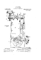
- Fig. 1 is a side elevation of my improved form of milling machine complete as seen from the left of the front of the machine.
- Fig. 2 is a plan view of the'machine shown in Fig. 1 though drawn on a slightly smaller scale and having a few of the unimportant features omitted as for instance the oil pump and its connections.
- Fig. 3 is a central vertical cross sectional view of themachine as taken on line 3-3 of Fig. 2.
- Fig. 4 is-a detail plan view of a pawl and ratchet mechanism for indexing the rotary table and work'carried thereby, to be slotted.
- Fig. 5 is a detached plan view of one of the knitting machine ring plates partially slotted as produced by my improved machine.
- Fig. 6 is an enlarged plan view of Specification orremii-rmni, Application 11:11 April 17, 1911. Serial m. 1121,0915,
- Fig. 7 is a detail 'side edge view ing slides in end elevation
- Fig. 8 is a detail longltudinal crosssectional view of v of apart of the said a rotary table showing one of the screw holda portion of the rotary table including a holding slide and punch for throwing the said screws out.
- FIG. 10 represents a bench upon which the machine is mounted the same having a to inclined toward an oil pot 11 arranged beneath.
- the machine proper which includes a bed 12 supported upon short legs.
- a bracket 13 is secured to the rear of the side portion of this bed and serves to support a worm shaft 14 connected by a clutch 15 with the driving pulleys 161 A.
- worm gear 17 mounted upon a-cam shaft 18 meshes with and is driven by the worm on the worm shaft.
- the cam shaft 18 is suitably journaled in bearings 19 secured to the top of the rear portion of the bed and upon it is mounted four cams 20, 21, 22 and 23.
- the first mentioned two of these cams are designed to operate the mechanism for successively rotating and locking the rotary table in position while the cams 22 and 23 serve to guide the cutter wheel across and into the work as will later be described.
- a vertically operating head 27 is slidably mounted upon the forwhich I will later seated in the head and upon the forward end of the slide.
- a bearing 29 is adju'stably mounted inthe face of the head 27 and is adapted to be raised or lowered by means of an adjusting screw 30.
- This bearing serves for the main spindle 31 that is provided with pulleys 32 upon one end and a cutter 33 upon the other end for operating upon the work,
- a lever 34 is pivoted to a bracket 35 andvhas its rear end in engagement with and is operated by a cam 22 while its forward end is provided with an adjustable pin 36 that engages an adjustable block 37 secured to the head 27 that carries the bearing, spindle and cutter.
- the said cam 22 thus serves to operate the lever to press down the head, cutter, etc., against the action of the springs 28 as for the pur ose of making a deeper out.
- a ro 38 mounted in suitable bearings on the bed of the machine is connected to operate thev clutch 15 before mentioned.
- a spring 39 seated upon this operating rod serves to hold the clutch in a disen aged position, but is held in engagement y a trip lever 40 also pivoted to the bed and designed to be tripped by the engagement therewith of a lug 41 on the rotary table 42.
- a bearing 43 In the forward end of the bed is secured a bearing 43 having a central vertical hole therethrough for the reception of the vertically disposed spindle 44 that carries the work carrying table.
- a ratchet wheel 45 is secured to the lower end of the spindle 44 and is designed to be successively operated by a pawl 46 pivotally mounted upon an arm 47 hinged upon a collar 48 secured to the spindle.
- the arm '47 is thrown backward and forward by the cam 20 which directly acts upon the vertically disposed slide 49 that has a bevel face side which serves to engage and operate the connecting rod 50 against the action of spring 51.
- the forward end of this rod is connected with the arm 47 carrying the pawl to engage the ratchet wheel.
- a holding stop 52 that is slidably mounted in brackets secured to the underside of the bed and has its opposite end in engagement with a second vertical slide 53 that is manipulated by the cam 22 mounted upon the cam shaft, and is provided with an inclined edge that engages a pin on outer edge of slidable holding stop.
- a spring 54 serves to normally hold this stop in a forward position and in engagement with a tooth of the ratchet wheel uring the cutting operation while the cam serves to withdraw the stop when it is desired to turn the same forward in position for further operation.
- the ratchet wheel 9 its table may be operated step by step for the successive cuttin operation, and that the said table is positively locked during the said cut-ting operations, and that when the table makes acomplete rotation its lug 41 will strike the lever 40 and release the rod that frees the clutch and stops the machine.
- I also provide additional means for stopping therotary table with the completion of its rotary movement which consists in providing a hole in the.
- the pin is slidably mounted in the bed of the machine and connected with a lever 56 that is pivoted to a stud secured t0 the under side of the bed.
- the work to be slotted is obviously carried upon the table which as before stated is successively rotated so as to move the same step by step to bring the work forward to receive the respective-cuts.
- the work to be operated upon is a plate or ring 57 such as is shown on the machine in Fi 3 and in plan view in Fig. 5, I elect to hold it in position by means of an expandible split rin 58 seated against the inside of the plate an having an inner beveled edge against which a tapered clamp 59 is seated and held b means of a screw 60 see Fig.3.
- this plate can readily be released by simply loosening the screw and allowin the-ring 58 to retract and relieve the sai plate 57 when completed, and another blank set in place to be similarly operated upon.
- the table 42 is provided with a series of radial slots 61 forming ways to receive a fixed die 62 and a slidable clamp 63.
- a spring 64 Beneath this clamp and in a pocket of the table is seated a spring 64 that is arranged interlnediate of the shoulder in end of pocket of the table and a lug 65 on the slide.
- This spring thus arranged tends to normally draw the clamp out, leaving a suitable space, in the slot between the die and clamp to receive and loosely carry a screw 68 when placed therein.
- a block 66 is secured to the bed 12 of the machine beneath the cutter wheel and serves to support a ing drawn in against the spring and at such times as when the screw or die is positioned beneath the cutter.
- a rotary cutting tool of a bed, a driving shaft, a vertical spindle mounted in the bed, a pawl and ratchet for intermittently rotating the spindle, a spring actuated horizontal slide beneath the bed and connected with the pawl for operating the ratchet, a vertical slide operated by the driving shaft to manipulate the said slide, a spring actuated slidable holding-stop also arranged beneath the bed and adapted to engage the ratchet, a vertical slide operated by the driving shaft and adapted to operate the holding-stop to secure the ratchet in position, a rotary work carrying table mounted on the spindle and having a hole therein, a spring actuated stop pin to engage the table and having an operating handle for its withdrawal, and means for securing the work in position upon the table.
Landscapes
- Engineering & Computer Science (AREA)
- Mechanical Engineering (AREA)
- Control Of Cutting Processes (AREA)
Description
C. E. BILTON.
MILLING MACHINE. APPLIOATION FILED APB.17, 1911.
Patented May 20, 1913.
4 SHEETS-SHEET 1.
INVENTOR 01a ren ce 1'. jB-flfim C. E. BILTON.
MILLING MACHINE.
APPLICATION FILED APR. 17, 1911.
Patented May 20, 1913.
4 SHEETS-SHEET 2.
O. E. BILTON.
MILLING MACHINE.
APPLIOATION FILED APR.17, 1911.
Patented May 20, 1913.
4 SHEETS-SHEET 4.
QM K Q7/4114 INVENTOR C'l arence 15'. 3 7101 the slotting of other forms or parts as for .ments of parts through which the above ob- STATES PATENT OFFICE.
CLARENCE E. BILTON, OI BBIDGEPOBT, CONNECTICUT, ASSIGNOB TO'THE STANDARD MANUFACTURING CO IPAN-Y, OI BRIDGEPOBT, CONNECTICUT, A CORPORATION 01' I CONNECTICUT.
To all whom it may concern:
Be it known that I, CLARENCE E. BILTON, acitizen of the United States, and resident of Bridgeport, in the county of Fairfield and State of Connecticut, have invented certain new and useful Improvements in Milling-Machines, of which the following is a specification.
This invention relates to new and useful improvements in milling machines and more particularly to a slotting machine, whereby -slots of different width, depth and length can be automatically produced, in disks, plates, screws or other parts.
The particular object of my invention is to improve upon a commercial form of milling machine whereby it will be better adapted for special work, as for instance ofradially slotting round metal plates such as are employed upon knitting machines, or for instance the heads ofmachine screws, and finally to simplify, cheapen and generally improve the construction of machines of this class whereby they may be made to take in a larger variety of work and beconstructed at a comparatively small cost.
The invention further consists in certain novel features of construction and arrangejects are obtained, as will be more fully understood from the accompanying drawings, forming a part of this specification, upon which similar characters of referencewill be found to designate likeor corresponding parts throughout'the several figures andof Figure 1, is a side elevation of my improved form of milling machine complete as seen from the left of the front of the machine. Fig. 2, is a plan view of the'machine shown in Fig. 1 though drawn on a slightly smaller scale and having a few of the unimportant features omitted as for instance the oil pump and its connections. Fig. 3, is a central vertical cross sectional view of themachine as taken on line 3-3 of Fig. 2. Fig. 4, is-a detail plan view of a pawl and ratchet mechanism for indexing the rotary table and work'carried thereby, to be slotted. Fig. 5, is a detached plan view of one of the knitting machine ring plates partially slotted as produced by my improved machine. Fig. 6, is an enlarged plan view of Specification orremii-rmni, Application 11:11 April 17, 1911. Serial m. 1121,0915,
a modified form: of rotary table with a,
mLLme-umnmn.
Patented May 20, 1913.
special form of holding devicefor retaining screws wh1le being slotted. Fig. 7, is a detail 'side edge view ing slides in end elevation, and Fig. 8, is a detail longltudinal crosssectional view of v of apart of the said a rotary table showing one of the screw holda portion of the rotary table including a holding slide and punch for throwing the said screws out.
The-main driving mechanism and operat- 1ng conncctions of this machine, are ver similar to that shown inmy allowed appl1 cation for patent on improvements in gear cutting machines Serial #890,460.
The feature of novelty herein, includes changes of construction made necessary to adapt the machine for the special work heretofore referred to, and describe in detail, after briefly describin the method of construction and operation 0 the necessary driving mechanism for operating said novel mechanisms.
Referring therefore to the numerals of reference marked upon the drawings 10 represents a bench upon which the machine is mounted the same having a to inclined toward an oil pot 11 arranged beneath. Upon the bench is arranged the machine proper which includes a bed 12 supported upon short legs. A bracket 13 is secured to the rear of the side portion of this bed and serves to support a worm shaft 14 connected by a clutch 15 with the driving pulleys 161 A. worm gear 17 mounted upon a-cam shaft 18 meshes with and is driven by the worm on the worm shaft. The cam shaft 18 is suitably journaled in bearings 19 secured to the top of the rear portion of the bed and upon it is mounted four cams 20, 21, 22 and 23. The first mentioned two of these cams are designed to operate the mechanism for successively rotating and locking the rotary table in position while the cams 22 and 23 serve to guide the cutter wheel across and into the work as will later be described. 24
represents a heavy bracket secured to the right hand side of the machine and which is provided with ways to receive a slide 25, the rear end of which is provided with an adjustable block 26 that bears a roll to engage the cam groove of cam 23 for the purpose of reciprocating the slide backward and forward as occasion requires to draw the cutter throughthe work. A vertically operating head 27 is slidably mounted upon the forwhich I will later seated in the head and upon the forward end of the slide.
A bearing 29 is adju'stably mounted inthe face of the head 27 and is adapted to be raised or lowered by means of an adjusting screw 30. This bearing serves for the main spindle 31 that is provided with pulleys 32 upon one end and a cutter 33 upon the other end for operating upon the work, A lever 34 is pivoted to a bracket 35 andvhas its rear end in engagement with and is operated by a cam 22 while its forward end is provided with an adjustable pin 36 that engages an adjustable block 37 secured to the head 27 that carries the bearing, spindle and cutter. The said cam 22 thus serves to operate the lever to press down the head, cutter, etc., against the action of the springs 28 as for the pur ose of making a deeper out.
A ro 38 mounted in suitable bearings on the bed of the machine is connected to operate thev clutch 15 before mentioned. A spring 39 seated upon this operating rod serves to hold the clutch in a disen aged position, but is held in engagement y a trip lever 40 also pivoted to the bed and designed to be tripped by the engagement therewith of a lug 41 on the rotary table 42. In the forward end of the bed is secured a bearing 43 having a central vertical hole therethrough for the reception of the vertically disposed spindle 44 that carries the work carrying table.
A ratchet wheel 45 is secured to the lower end of the spindle 44 and is designed to be successively operated by a pawl 46 pivotally mounted upon an arm 47 hinged upon a collar 48 secured to the spindle. The arm '47 is thrown backward and forward by the cam 20 which directly acts upon the vertically disposed slide 49 that has a bevel face side which serves to engage and operate the connecting rod 50 against the action of spring 51. The forward end of this rod is connected with the arm 47 carrying the pawl to engage the ratchet wheel.
In addition to the foregoing described mechanism for operating the ratchet wheel and its rotary table I provide a holding stop 52 that is slidably mounted in brackets secured to the underside of the bed and has its opposite end in engagement with a second vertical slide 53 that is manipulated by the cam 22 mounted upon the cam shaft, and is provided with an inclined edge that engages a pin on outer edge of slidable holding stop. A spring 54 serves to normally hold this stop in a forward position and in engagement with a tooth of the ratchet wheel uring the cutting operation while the cam serves to withdraw the stop when it is desired to turn the same forward in position for further operation.
From the foregoin it will be seen that the ratchet wheel 9? its table may be operated step by step for the successive cuttin operation, and that the said table is positively locked during the said cut-ting operations, and that when the table makes acomplete rotation its lug 41 will strike the lever 40 and release the rod that frees the clutch and stops the machine. I also provide additional means for stopping therotary table with the completion of its rotary movement which consists in providing a hole in the.
underside of the table into which a spring 28' actuated stop pin 55 is forced when the hole is brought into registration with the said pin. The pin is slidably mounted in the bed of the machine and connected with a lever 56 that is pivoted to a stud secured t0 the under side of the bed.
In order to release the table and allow it to rot-ate, the outer free end of the lever is pressed down to withdraw the pin from the table, against the action of its spring in a manner to allow the table to be started on its turning operation.
The work to be slotted is obviously carried upon the table which as before stated is successively rotated so as to move the same step by step to bring the work forward to receive the respective-cuts. If the work to be operated upon is a plate or ring 57 such as is shown on the machine in Fi 3 and in plan view in Fig. 5, I elect to hold it in position by means of an expandible split rin 58 seated against the inside of the plate an having an inner beveled edge against which a tapered clamp 59 is seated and held b means of a screw 60 see Fig.3. Thus it wi 1 .be seen that this plate can readily be released by simply loosening the screw and allowin the-ring 58 to retract and relieve the sai plate 57 when completed, and another blank set in place to be similarly operated upon.
If the machine is to be used for slotting the heads of screws and the like, a slightly difi'erentiform of rotary table is required, that is, one having a suitable series of pockets and clamps therein to receive the screws to be operated upon. Such a form of modification is shown in Figs. 6 to 8 inclusive,
and wherein the table 42 is provided with a series of radial slots 61 forming ways to receive a fixed die 62 and a slidable clamp 63. Beneath this clamp and in a pocket of the table is seated a spring 64 that is arranged interlnediate of the shoulder in end of pocket of the table and a lug 65 on the slide. This spring thus arranged tends to normally draw the clamp out, leaving a suitable space, in the slot between the die and clamp to receive and loosely carry a screw 68 when placed therein. A block 66 is secured to the bed 12 of the machine beneath the cutter wheel and serves to support a ing drawn in against the spring and at such times as when the screw or die is positioned beneath the cutter. The movement of the pawl and ratchet wheel with each operation would be just sufiicient .to move the table shown, of a turn which is equal to that of the distance between the clamps. After the screws have been slotted as shown in Fig. 6, they are moved forward a couple of stations and thus brought immediately above a punch 69 seated in the end of a lever 70 that is pivoted to a bracket 71 secured to the bed and connected to be op erated by the cam 21.
From the foregoing it will be seen that, with each movement of the table a slotted screw is brought immediately over the punch, and that during the slotting operation, upon another screw, the lever is operated by the cam 21 in a manner to cause the punch to knock out such finished screw thus leaving the pocket free to have another screw placed therein while the table is moving around.
Having thus described my invention what I claim and desire to secure by Letters Patent is 1. In a milling machine of the class described, the combination with a rotary cutting tool, of a bed, a driving shaft, a vertical spindle mounted in the bed, a pawl and ratchet for intermittently rotating the spindle, a connecting rod beneath the bed and connected with the pawl for operating the ratchet, a vertical slide operated by the driving shaft to manipulate the said rod, a slidable holding stop also arranged beneath the bed and adapted to engage the ratchet, a vertical slide operated by the driving shaft and adapted to operate the holding stop to secure the ratchet in position, a horizontally arranged work carrying table mounted on the spindle, and means for securing thework in position upon the table.
2. In a milling machine of the class described, the combination with a rotary cutting tool, of a bed, a driving shaft, a vertical spindle mounted in the bed, a pawl and ratchet for intermittently rotating the spindle, a spring actuated horizontal slide beneath the bed and connected with the pawl for operating the ratchet, a vertical slide operated by the driving shaft to manipulate the said slide, a spring actuated slidable holding-stop also arranged beneath the bed and adapted to engage the ratchet, a vertical slide operated by the driving shaft and adapted to operate the holding-stop to secure the ratchet in position, a rotary work carrying table mounted on the spindle and having a hole therein, a spring actuated stop pin to engage the table and having an operating handle for its withdrawal, and means for securing the work in position upon the table.
Signed at Bridgeport in the county of Fairfield and State of Connecticut this 11th day of April A. D., 1911.
CLARENCE E. BILTON. Witnesses:
C. M. NEWMAN, RUTH M. VVORDEN.
Priority Applications (1)
| Application Number | Priority Date | Filing Date | Title |
|---|---|---|---|
| US62169511A US1061973A (en) | 1911-04-17 | 1911-04-17 | Milling-machine. |
Applications Claiming Priority (1)
| Application Number | Priority Date | Filing Date | Title |
|---|---|---|---|
| US62169511A US1061973A (en) | 1911-04-17 | 1911-04-17 | Milling-machine. |
Publications (1)
| Publication Number | Publication Date |
|---|---|
| US1061973A true US1061973A (en) | 1913-05-20 |
Family
ID=3130219
Family Applications (1)
| Application Number | Title | Priority Date | Filing Date |
|---|---|---|---|
| US62169511A Expired - Lifetime US1061973A (en) | 1911-04-17 | 1911-04-17 | Milling-machine. |
Country Status (1)
| Country | Link |
|---|---|
| US (1) | US1061973A (en) |
Cited By (5)
| Publication number | Priority date | Publication date | Assignee | Title |
|---|---|---|---|---|
| US2473536A (en) * | 1944-09-18 | 1949-06-21 | Mccoy Harry Ephriam | Device to reproduce timing disks |
| US2520514A (en) * | 1947-10-16 | 1950-08-29 | Spector Irving | Automatic self-indexing commutator slotter |
| US2645979A (en) * | 1948-09-15 | 1953-07-21 | Haesler Giauque & Cie | Milling attachment for universal machine tools |
| US2688904A (en) * | 1946-02-23 | 1954-09-14 | Paramount Textile Mach Co | Indexing mechanism for machine tools |
| US3103146A (en) * | 1959-03-26 | 1963-09-10 | Bechler Andre | Automatic lathe |
-
1911
- 1911-04-17 US US62169511A patent/US1061973A/en not_active Expired - Lifetime
Cited By (5)
| Publication number | Priority date | Publication date | Assignee | Title |
|---|---|---|---|---|
| US2473536A (en) * | 1944-09-18 | 1949-06-21 | Mccoy Harry Ephriam | Device to reproduce timing disks |
| US2688904A (en) * | 1946-02-23 | 1954-09-14 | Paramount Textile Mach Co | Indexing mechanism for machine tools |
| US2520514A (en) * | 1947-10-16 | 1950-08-29 | Spector Irving | Automatic self-indexing commutator slotter |
| US2645979A (en) * | 1948-09-15 | 1953-07-21 | Haesler Giauque & Cie | Milling attachment for universal machine tools |
| US3103146A (en) * | 1959-03-26 | 1963-09-10 | Bechler Andre | Automatic lathe |
Similar Documents
| Publication | Publication Date | Title |
|---|---|---|
| US1061973A (en) | Milling-machine. | |
| US1967689A (en) | Cam controlled multispindle machine | |
| US3008382A (en) | Machine tool | |
| US2383266A (en) | Feed carriage assembly for lathes | |
| US323175A (en) | Machine for cutting teeth of duplex wheels | |
| US1836954A (en) | Metal working machine | |
| US1906875A (en) | Paper cutting machine | |
| US904866A (en) | Multispindle-machine. | |
| US1696027A (en) | Automatic multiple-spindle lathe | |
| US2993417A (en) | Method and apparatus for machining the ends of the teeth of gear wheels and similar workpieces | |
| US511817A (en) | Screw-making machine | |
| US673015A (en) | Boring, reaming, and threading machine. | |
| US1268386A (en) | Turret-lathe. | |
| US925867A (en) | Multispindle metal-grinding machine. | |
| US1938783A (en) | Milling machinery | |
| US1685319A (en) | Metal-working machine | |
| US1778956A (en) | Automatic machine for making metal plugs for barrels | |
| US1389308A (en) | Slotting-machine | |
| US1865198A (en) | Milling machine | |
| US530179A (en) | Screw-making machine | |
| US2017913A (en) | Milling machine | |
| US1330897A (en) | Milling-machine | |
| US1451097A (en) | Gear-cutting machine | |
| US409665A (en) | bkownell | |
| US993158A (en) | Apparatus for machining ends of metal blanks. |