US10618490B2 - Occupant ankle protection apparatus for vehicle - Google Patents
Occupant ankle protection apparatus for vehicle Download PDFInfo
- Publication number
- US10618490B2 US10618490B2 US15/826,099 US201715826099A US10618490B2 US 10618490 B2 US10618490 B2 US 10618490B2 US 201715826099 A US201715826099 A US 201715826099A US 10618490 B2 US10618490 B2 US 10618490B2
- Authority
- US
- United States
- Prior art keywords
- occupant
- airbag cushion
- side portions
- center portion
- ankles
- Prior art date
- Legal status (The legal status is an assumption and is not a legal conclusion. Google has not performed a legal analysis and makes no representation as to the accuracy of the status listed.)
- Active, expires
Links
- 210000003423 ankle Anatomy 0.000 title claims abstract description 94
- 238000000926 separation method Methods 0.000 claims description 20
- 208000027418 Wounds and injury Diseases 0.000 abstract description 5
- 230000006378 damage Effects 0.000 abstract description 5
- 208000014674 injury Diseases 0.000 abstract description 5
- 238000007792 addition Methods 0.000 description 2
- 210000002683 foot Anatomy 0.000 description 2
- 239000000446 fuel Substances 0.000 description 2
- 210000002414 leg Anatomy 0.000 description 2
- 206010024453 Ligament sprain Diseases 0.000 description 1
- 208000010040 Sprains and Strains Diseases 0.000 description 1
- 208000022542 ankle injury Diseases 0.000 description 1
- 238000002485 combustion reaction Methods 0.000 description 1
- 238000005516 engineering process Methods 0.000 description 1
- 210000003127 knee Anatomy 0.000 description 1
- 230000004048 modification Effects 0.000 description 1
- 238000012986 modification Methods 0.000 description 1
- 239000003208 petroleum Substances 0.000 description 1
- 238000006467 substitution reaction Methods 0.000 description 1
Images


Classifications
-
- B—PERFORMING OPERATIONS; TRANSPORTING
- B60—VEHICLES IN GENERAL
- B60R—VEHICLES, VEHICLE FITTINGS, OR VEHICLE PARTS, NOT OTHERWISE PROVIDED FOR
- B60R21/00—Arrangements or fittings on vehicles for protecting or preventing injuries to occupants or pedestrians in case of accidents or other traffic risks
- B60R21/02—Occupant safety arrangements or fittings, e.g. crash pads
- B60R21/16—Inflatable occupant restraints or confinements designed to inflate upon impact or impending impact, e.g. air bags
- B60R21/20—Arrangements for storing inflatable members in their non-use or deflated condition; Arrangement or mounting of air bag modules or components
- B60R21/205—Arrangements for storing inflatable members in their non-use or deflated condition; Arrangement or mounting of air bag modules or components in dashboards
- B60R21/206—Arrangements for storing inflatable members in their non-use or deflated condition; Arrangement or mounting of air bag modules or components in dashboards in the lower part of dashboards, e.g. for protecting the knees
-
- B—PERFORMING OPERATIONS; TRANSPORTING
- B60—VEHICLES IN GENERAL
- B60R—VEHICLES, VEHICLE FITTINGS, OR VEHICLE PARTS, NOT OTHERWISE PROVIDED FOR
- B60R21/00—Arrangements or fittings on vehicles for protecting or preventing injuries to occupants or pedestrians in case of accidents or other traffic risks
- B60R21/02—Occupant safety arrangements or fittings, e.g. crash pads
- B60R21/16—Inflatable occupant restraints or confinements designed to inflate upon impact or impending impact, e.g. air bags
- B60R21/23—Inflatable members
- B60R21/231—Inflatable members characterised by their shape, construction or spatial configuration
- B60R21/233—Inflatable members characterised by their shape, construction or spatial configuration comprising a plurality of individual compartments; comprising two or more bag-like members, one within the other
-
- B—PERFORMING OPERATIONS; TRANSPORTING
- B60—VEHICLES IN GENERAL
- B60R—VEHICLES, VEHICLE FITTINGS, OR VEHICLE PARTS, NOT OTHERWISE PROVIDED FOR
- B60R21/00—Arrangements or fittings on vehicles for protecting or preventing injuries to occupants or pedestrians in case of accidents or other traffic risks
- B60R21/02—Occupant safety arrangements or fittings, e.g. crash pads
- B60R21/16—Inflatable occupant restraints or confinements designed to inflate upon impact or impending impact, e.g. air bags
- B60R21/23—Inflatable members
- B60R21/231—Inflatable members characterised by their shape, construction or spatial configuration
- B60R21/2334—Expansion control features
- B60R21/2338—Tethers
-
- B—PERFORMING OPERATIONS; TRANSPORTING
- B60—VEHICLES IN GENERAL
- B60R—VEHICLES, VEHICLE FITTINGS, OR VEHICLE PARTS, NOT OTHERWISE PROVIDED FOR
- B60R21/00—Arrangements or fittings on vehicles for protecting or preventing injuries to occupants or pedestrians in case of accidents or other traffic risks
- B60R2021/003—Arrangements or fittings on vehicles for protecting or preventing injuries to occupants or pedestrians in case of accidents or other traffic risks characterised by occupant or pedestian
- B60R2021/0039—Body parts of the occupant or pedestrian affected by the accident
- B60R2021/0046—Feet
-
- B—PERFORMING OPERATIONS; TRANSPORTING
- B60—VEHICLES IN GENERAL
- B60R—VEHICLES, VEHICLE FITTINGS, OR VEHICLE PARTS, NOT OTHERWISE PROVIDED FOR
- B60R21/00—Arrangements or fittings on vehicles for protecting or preventing injuries to occupants or pedestrians in case of accidents or other traffic risks
- B60R21/02—Occupant safety arrangements or fittings, e.g. crash pads
- B60R21/16—Inflatable occupant restraints or confinements designed to inflate upon impact or impending impact, e.g. air bags
- B60R21/23—Inflatable members
- B60R21/231—Inflatable members characterised by their shape, construction or spatial configuration
- B60R2021/23176—Inflatable members characterised by their shape, construction or spatial configuration specially adapted for foot protection
-
- B—PERFORMING OPERATIONS; TRANSPORTING
- B60—VEHICLES IN GENERAL
- B60R—VEHICLES, VEHICLE FITTINGS, OR VEHICLE PARTS, NOT OTHERWISE PROVIDED FOR
- B60R21/00—Arrangements or fittings on vehicles for protecting or preventing injuries to occupants or pedestrians in case of accidents or other traffic risks
- B60R21/02—Occupant safety arrangements or fittings, e.g. crash pads
- B60R21/16—Inflatable occupant restraints or confinements designed to inflate upon impact or impending impact, e.g. air bags
- B60R21/23—Inflatable members
- B60R21/231—Inflatable members characterised by their shape, construction or spatial configuration
- B60R21/2334—Expansion control features
- B60R21/2338—Tethers
- B60R2021/23382—Internal tether means
-
- B—PERFORMING OPERATIONS; TRANSPORTING
- B60—VEHICLES IN GENERAL
- B60R—VEHICLES, VEHICLE FITTINGS, OR VEHICLE PARTS, NOT OTHERWISE PROVIDED FOR
- B60R21/00—Arrangements or fittings on vehicles for protecting or preventing injuries to occupants or pedestrians in case of accidents or other traffic risks
- B60R21/02—Occupant safety arrangements or fittings, e.g. crash pads
- B60R21/16—Inflatable occupant restraints or confinements designed to inflate upon impact or impending impact, e.g. air bags
- B60R21/23—Inflatable members
- B60R21/231—Inflatable members characterised by their shape, construction or spatial configuration
- B60R21/2334—Expansion control features
- B60R21/2338—Tethers
- B60R2021/23386—External tether means
Definitions
- the present disclosure relates to an occupant ankle protection apparatus for a vehicle that prevents the occupant's ankles from being injured during a vehicle collision.
- an airbag has been used as an effective device for preventing an occupant from an external impact.
- An airbag which is a device for protecting vehicle occupants during a collision, includes a collision sensor configured to sense a vehicle collision, a controller configured to operate the airbag, based on the sensing result of the collision sensor, and an airbag module configured to operate the airbag in response to a signal from the controller, and is classified into a driver airbag, an occupant airbag, a side airbag, and a roof airbag based on the mounting position of the airbag or the occupants subject to protection from the collision.
- the present disclosure provides an occupant ankle protection apparatus for a vehicle for preventing the occupant's ankles from being injured during a vehicle collision.
- An occupant ankle protection apparatus for a vehicle may include an airbag cushion folded in an airbag housing, connected to an inflator in the airbag housing, and configured to deploy toward ankles of an occupant when the inflator is operated such that a center portion of the airbag cushion protrudes further toward the occupant than both side portions of the airbag cushion whereby the center portion is inserted between the ankles of the occupant and the side portions support fronts of the ankles of the occupant.
- the airbag cushion may be disposed inside an indoor panel disposed above an occupant and may be configured to deploy down toward both ankles of the occupant.
- the airbag cushion may be formed in a T-shape with the center portion thereof protruding down further than the side portions when deployed.
- the side portions may be curved downward at ends to cover fronts and outer sides of both ankles of an occupant when the airbag cushion deploys.
- the apparatus may further include outer tethers of which first ends connected to ends of the side portions and second ends connected to sides or a lower end of the center portion to pull the ends of the side portions toward the center portion in contact with ankles of an occupant and thus, the side portions may cover the ankles of the occupant when the airbag cushion deploys.
- the center portion may be formed to be tapered downward when the airbag cushion deploys.
- the airbag cushion may further have a separation wall that crosses the center portion horizontally and has one or more apertures so that the side portions expand and then a protruding portion of the center portion expands when the airbag cushion deploys.
- the separation wall may be disposed in the airbag cushion at a position where the center portion protrudes further than the side portions.
- lids may be disposed on the separation wall to close the apertures and inner tethers may be connected to the lids at first ends and connected to the side portions at second ends to be pulled with the lids by expansion of the side portions to open the apertures previously closed by the lids when the airbag cushion deploys.
- the occupant ankle protection apparatus for a vehicle of the present disclosure when an airbag cushion deploys, side portions support the fronts of both ankles of an occupant and a center portion is inserted between the ankles and supports the inner sides of the ankles, thereby preventing the ankles of the occupant from being injured. Accordingly, the ankles of an occupant may be protected and the occupant may escape from a vehicle after a vehicle collision, thus preventing a secondary accident.
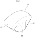
- FIG. 1 is a view showing an occupant ankle protection apparatus for a vehicle according to an exemplary embodiment of the present disclosure
- FIG. 2 is an assembly view of the occupant ankle protection apparatus for a vehicle shown in FIG. 1 according to an exemplary embodiment of the present disclosure
- FIGS. 3 to 7 are views illustrating the occupant ankle protection apparatus for a vehicle shown in FIG. 1 according to an exemplary embodiment of the present disclosure.
- vehicle or “vehicular” or other similar term as used herein is inclusive of motor vehicles in general such as passenger automobiles including sports utility vehicles (SUV), buses, trucks, various commercial vehicles, watercraft including a variety of boats and ships, aircraft, and the like, and includes hybrid vehicles, electric vehicles, combustion, plug-in hybrid electric vehicles, hydrogen-powered vehicles and other alternative fuel vehicles (e.g. fuels derived from resources other than petroleum).
- motor vehicles in general such as passenger automobiles including sports utility vehicles (SUV), buses, trucks, various commercial vehicles, watercraft including a variety of boats and ships, aircraft, and the like, and includes hybrid vehicles, electric vehicles, combustion, plug-in hybrid electric vehicles, hydrogen-powered vehicles and other alternative fuel vehicles (e.g. fuels derived from resources other than petroleum).
- SUV sports utility vehicles
- plug-in hybrid electric vehicles e.g. fuels derived from resources other than petroleum
- FIG. 1 is a view showing an occupant ankle protection apparatus for a vehicle according to an exemplary embodiment of the present disclosure
- FIG. 2 is an assembly view of the occupant ankle protection apparatus for a vehicle shown in FIG. 1
- FIGS. 3 to 7 are views illustrating the occupant ankle protection apparatus for a vehicle shown in FIG. 1 .
- An occupant ankle protection apparatus for a vehicle may include an airbag cushion that is folded in an airbag housing 10 , is connected to an inflator in the airbag housing 10 , and configured to deploy toward the ankles A or feet area of an occupant when the inflator 20 is operated with a center portion 32 thereof protruding further toward the occupant than both side portions 34 . Accordingly, the center portion 32 may be inserted between the ankles A of the occupant and the side portions 34 may support the fronts of the ankles A of the occupant.
- the center portion 32 protrudes further toward an occupant than the side portions 34 and may contact and support the inner sides of both ankles A of the occupant and the side portions 34 may contact with and support the fronts of the ankles A of the occupant. Accordingly, when the airbag deploys, the center portion 32 may be inserted between both ankles of the occupant and prevent the ankles A of the occupant from transversely moving and both side portions 34 may support the fronts of the ankles A, to thus protect the ankles A from an external impact and prevent the ankles A from being injured (e.g., sprained).
- both side portions 34 may support the fronts of both ankles A of an occupant and the center portion 32 may be inserted between the ankles A of the occupant, and thus, the ankles A of the occupant may be prevented from being injured, and thus, injury to the ankles A of the occupant may be minimized during a vehicle collision.
- the airbag cushion 30 may be disposed inside an indoor panel P disposed above an occupant to be able to deploy down toward both ankles A of the occupant.
- the indoor panel P which is a panel disposed under the steering wheel, is disposed over the legs of an occupant.
- the airbag cushion 30 is received inside the airbag housing 10 and connected to the inflator 20 to be supplied with gas from the inflator 20 .
- the inflator 20 and the airbag cushion 30 may be folded inside the airbag housing 10 to allow the airbag cushion 30 to be deployed by gas from the inflator 20 in a collision.
- the airbag housing 10 may be fixed inside the indoor panel P by specific brackets and the airbag cushion 30 may be configured to deploy toward the fronts of both ankles A of an occupant A, and thus, the open side of the airbag housing 10 may be formed at the lower end.
- the airbag cushion 30 may deploy in a T-shape with the center portion 32 protruding further downward than the side portions 34 .
- the airbag cushion 30 may be formed in a T-shape and thus, the side portions 34 may contact and support the fronts of both ankles A of an occupant and the center portion 32 may protrude further downward than the side portions 34 to be inserted between the ankles A of the occupant when the airbag cushion 30 deploys. Accordingly, when the airbag cushion 30 deploys, the center portion 32 may be inserted between both ankles of the occupant to prevent the ankles A of the occupant from transversely moving and both sides portions 34 may support the fronts of the ankles A to protect the ankles A from an external impact and prevent the ankles A from being injured.
- the ends of the side portions 34 may be curved downward to cover the fronts and the outer sides of both ankles A of an occupant when the airbag cushion 30 deploys.
- This configuration prevents both ankles A of an occupant from transversely moving. Accordingly, since the ends of both side portions 34 of the airbag cushion 30 may be curved downward, the fronts and outer sides of the ankles A of the occupant may be covered and, the center portion 32 may be inserted between the ankles A, thereby covering the inner sides of the ankles A of the occupant.
- the airbag cushion 30 may further include outer tethers 50 of which first ends may be connected to the ends of the side portions 34 and second ends may be connected to the sides or the lower end of the center portion 32 .
- the outer tethers 50 connected to the ends of the side portions 34 and the center portion 32 may be tensioned in contact with the ankles A of an occupant.
- the outer tethers 50 may be pushed by the ankles A of the occupant and the ends of the side portions 34 connected to the outer tethers 50 may be pulled, whereby the side portions 34 cover the ankles A of the occupant.
- the airbag cushion 30 may further include the outer tethers 50 connected to the ends of the side portions 34 and both sides of the center portion 32 , when the airbag cushion 30 deploys, the airbag cushion 30 may cover and fix the fronts, inner sides, and outer sides of both ankles A of an occupant, to prevent the ankles A of the occupant from moving transversely, to prevent injury, and to protect the occupant lower body from an external impact.
- the center portion 32 may be formed to be tapered downward when the airbag cushion 30 deploys. Since the center portion 32 of the airbag cushion 30 may be tapered downward, as described above, when the airbag cushion 30 deploys, the center portion 32 may be more easily inserted between both ankles A of an occupant more easily. Accordingly, even when both ankles A of an occupant are positioned close to each other (e.g., in contact with each other), the center portion 32 of the airbag cushion 30 may be inserted into the space between the ankles A of the occupant A to prevent transverse movement of the ankles A of the occupant.
- the airbag cushion 30 may further include a separation wall 40 that crosses the center portion 32 horizontally and may include one or more apertures 42 so that the side portions 34 expand and then the protruding portion of the center portion 32 expands when the airbag cushion 30 deploys.
- the separation wall 40 may be disposed in the airbag cushion 30 at a position where the center portion 32 further protrudes than the side portions 34 .
- the side portions 34 may expand first by the gas from the inflator 20 and then the gas may flow to the protruding portion of the center portion 32 through the apertures 42 of the separation wall 40 , to secondarily expand protruding portion of the center portion 32 .
- the size and number of the apertures 42 of the separation wall 40 may be set such that the side portions 34 are sufficiently expanded and then the protruding portion of the center portion 32 may be expanded thereafter.
- the airbag cushion 30 may further include a plurality of lids 44 on the separation wall 40 to close the apertures 42 and inner tethers 46 of which first ends may be connected to the lids 44 and second ends may be connected to the side portions 34 to be pulled with the lids 44 by expansion of the side portions 34 to open the apertures 42 when the airbag cushion 30 deploys.
- the lids 44 or covers used to close the apertures 42 of the separation wall 40 and the inner tethers 45 for opening the lids 44 when the airbag cushion 30 deploys are disposed inside the airbag cushion 30 , when the airbag cushion 30 deploys, the side portions 34 may expand first and then the protruding portion of the center portion 32 may expand downward thereafter.
- the apertures 42 of the separation wall 40 may be closed by the lids 44 .
- the side portions 34 expand first due to the gas from the inflator 20 being prevented from flowing to the protruding portion of the center portion 32 due to the apertures 42 of the separation wall 40 being closed by the lids 44 .
- the inner tethers 46 may be pulled and the lids 44 connected to the inner tethers 46 may also be pulled, and thus, the apertures 42 of the separation wall 40 may be opened. Accordingly, the gas from the inflator 40 may flow to the protruding portion of the center portion 32 through the apertures 42 after expanding the side portions 42 of the airbag cushion 30 , whereby the center portion 32 may expand and protrude downward.
- the center portion 32 may prevent the ankles A of the occupant from transversely moving by being inserted between the ankles A of the occupant. Therefore, it may be possible to minimize injury to the ankles A of an occupant when the airbag deploys, and to prevent the ankles from being sprained by completely fixing the ankles A of the occupant after the airbag deploys.
- the side portions support the fronts of both ankles A of an occupant and the center portion may be inserted between the ankles A and support the inner sides of the ankles A, thereby preventing the ankles A of the occupant from being injured. Therefore, the ankles of an occupant may be protected and the occupant may escape from a vehicle after a vehicle collision, thus preventing a secondary accident.
Landscapes
- Engineering & Computer Science (AREA)
- Mechanical Engineering (AREA)
- Air Bags (AREA)
Abstract
Description
Claims (12)
Applications Claiming Priority (2)
| Application Number | Priority Date | Filing Date | Title |
|---|---|---|---|
| KR10-2017-0104770 | 2017-08-18 | ||
| KR1020170104770A KR102452472B1 (en) | 2017-08-18 | 2017-08-18 | Occupant ankle protection apparatus for vehicle |
Publications (2)
| Publication Number | Publication Date |
|---|---|
| US20190054882A1 US20190054882A1 (en) | 2019-02-21 |
| US10618490B2 true US10618490B2 (en) | 2020-04-14 |
Family
ID=65234931
Family Applications (1)
| Application Number | Title | Priority Date | Filing Date |
|---|---|---|---|
| US15/826,099 Active 2038-06-22 US10618490B2 (en) | 2017-08-18 | 2017-11-29 | Occupant ankle protection apparatus for vehicle |
Country Status (4)
| Country | Link |
|---|---|
| US (1) | US10618490B2 (en) |
| KR (1) | KR102452472B1 (en) |
| CN (1) | CN109421644B (en) |
| DE (1) | DE102017221846A1 (en) |
Families Citing this family (5)
| Publication number | Priority date | Publication date | Assignee | Title |
|---|---|---|---|---|
| DE102017123193A1 (en) * | 2017-10-06 | 2019-04-11 | Trw Automotive Gmbh | Knee-airbag unit of a vehicle occupant restraint system of a motor vehicle |
| CN110182161A (en) * | 2019-04-19 | 2019-08-30 | 江苏敏安电动汽车有限公司 | A kind of vehicle airbag installations and its electric car of application |
| KR102623127B1 (en) * | 2019-07-08 | 2024-01-10 | 현대모비스 주식회사 | Roof airbar apparatus |
| KR20220128101A (en) * | 2021-03-12 | 2022-09-20 | 현대자동차주식회사 | Vehicle seat cushion airbag, its control system and control method |
| US12447921B1 (en) | 2024-09-16 | 2025-10-21 | Ford Global Technologies, Llc | Seat bottom mounted airbag assembly |
Citations (27)
| Publication number | Priority date | Publication date | Assignee | Title |
|---|---|---|---|---|
| US6464246B2 (en) * | 1999-04-13 | 2002-10-15 | Trw Vehicle Safety Systems Inc. | Vehicle occupant lower extremity protection apparatus |
| US20020149187A1 (en) * | 2001-04-11 | 2002-10-17 | Holtz Kimberlee D. | Soft-surface inflatable knee bolster airbag |
| US6685217B2 (en) * | 2001-05-21 | 2004-02-03 | Takata Corporation | Leg protection device for vehicle occupants |
| JP2004168280A (en) * | 2002-11-06 | 2004-06-17 | Toyoda Gosei Co Ltd | Driver protecting airbag device |
| US20060131847A1 (en) * | 2004-05-27 | 2006-06-22 | Toyoda Gosei Co., Ltd. | Side airbag device |
| US7066487B2 (en) | 2003-11-11 | 2006-06-27 | Ford Global Technologies, Llc | Airbag with internal positioning panels for sequential deployment |
| US7090245B2 (en) * | 2002-12-16 | 2006-08-15 | Takata Corporation | Leg protection system and vehicle having the same |
| KR20070107967A (en) | 2006-05-04 | 2007-11-08 | 현대자동차주식회사 | Knee Protection Airbag Structure of Car |
| KR100831500B1 (en) | 2006-07-18 | 2008-05-22 | 현대자동차주식회사 | Selective deployment airbag device for vehicle and control method |
| US20080122205A1 (en) * | 2006-11-24 | 2008-05-29 | Toyota Jidosha Kabushiki Kaisha | Knee airbag apparatus |
| US7604252B2 (en) * | 2006-02-24 | 2009-10-20 | Ford Global Technologies, Llc | Knee airbag |
| US7669897B2 (en) * | 2006-06-23 | 2010-03-02 | Nissan Motor Co., Ltd. | Vehicle passenger restraining apparatus and method for the same |
| US7744117B2 (en) * | 2006-11-07 | 2010-06-29 | Toyota Jidosha Kabushiki Kaisha | Knee airbag device for vehicle |
| US8215667B2 (en) * | 2008-10-29 | 2012-07-10 | Toyota Jidosha Kabushiki Kaisha | Knee airbag device for a vehicle |
| US8292323B2 (en) * | 2008-08-06 | 2012-10-23 | Toyota Jidosha Kabushiki Kaisha | Knee airbag device for vehicle |
| US9211860B2 (en) * | 2013-01-16 | 2015-12-15 | Toyota Jidosha Kabushiki Kaisha | Knee side face restraint airbag device |
| US9227590B2 (en) * | 2012-08-27 | 2016-01-05 | Toyota Jidosha Kabushiki Kaisha | Vehicle side airbag device |
| US9272681B1 (en) | 2014-11-25 | 2016-03-01 | Autoliv Asp, Inc. | Knee airbag deployable from a side panel |
| US9283916B2 (en) * | 2013-08-29 | 2016-03-15 | Fuji Jukogyo Kabushiki Kaisha | Occupant protection device |
| US9475445B2 (en) * | 2014-08-25 | 2016-10-25 | Ford Global Technologies, Llc | Vehicle airbag appendage |
| US20170057447A1 (en) * | 2015-08-31 | 2017-03-02 | Toyoda Gosei Co., Ltd. | Knee protecting air bag system |
| US9994181B1 (en) * | 2017-03-31 | 2018-06-12 | Ford Global Technologies, Llc | Vehicle seat including airbag |
| US20180319358A1 (en) * | 2017-05-03 | 2018-11-08 | Autoliv Asp, Inc. | Inflatable safety restraint system for protecting a rear seat occupant |
| US20190061667A1 (en) * | 2015-10-28 | 2019-02-28 | Takata Corporation | Occupant leg restraint device |
| US20190161045A1 (en) * | 2017-11-29 | 2019-05-30 | GM Global Technology Operations LLC | Airbag assembly configured to deploy from a side wall of a vehicle to resist upward motion of the leg of an occupant, and a system and method for controlling the airbag assembly |
| US10336283B2 (en) * | 2017-05-09 | 2019-07-02 | Autoliv Asp, Inc. | Oblique impact airbag mitts and related systems and methods |
| US10351091B2 (en) * | 2014-08-20 | 2019-07-16 | Takata Corporation | Occupant's leg restraint device and airbag for occupant's leg restraint device |
Family Cites Families (8)
| Publication number | Priority date | Publication date | Assignee | Title |
|---|---|---|---|---|
| US6832778B2 (en) * | 2002-07-19 | 2004-12-21 | Delphi Technologies, Inc. | Air bag restraint including selectively operable venting elements |
| US20050151351A1 (en) | 2004-01-12 | 2005-07-14 | Enders Mark L. | Fabric knee airbag for high internal pressures |
| JP5891210B2 (en) * | 2013-08-29 | 2016-03-22 | 富士重工業株式会社 | Crew protection device |
| JP2015085761A (en) | 2013-10-29 | 2015-05-07 | トヨタ自動車株式会社 | Crew protection device |
| KR20150124003A (en) * | 2014-04-25 | 2015-11-05 | 현대자동차주식회사 | Pedestrian airbag system for vehicle |
| KR102216133B1 (en) * | 2014-08-14 | 2021-02-16 | 현대모비스 주식회사 | Passenger Airbag of Vehicle |
| JP6451597B2 (en) * | 2015-11-06 | 2019-01-16 | トヨタ自動車株式会社 | Airbag device for driver's seat |
| CN105774737B (en) * | 2016-03-30 | 2018-04-27 | 延锋百利得(上海)汽车安全系统有限公司 | A kind of knee airbag device |
-
2017
- 2017-08-18 KR KR1020170104770A patent/KR102452472B1/en active Active
- 2017-11-29 US US15/826,099 patent/US10618490B2/en active Active
- 2017-12-04 DE DE102017221846.0A patent/DE102017221846A1/en active Pending
- 2017-12-06 CN CN201711274051.3A patent/CN109421644B/en active Active
Patent Citations (29)
| Publication number | Priority date | Publication date | Assignee | Title |
|---|---|---|---|---|
| US6464246B2 (en) * | 1999-04-13 | 2002-10-15 | Trw Vehicle Safety Systems Inc. | Vehicle occupant lower extremity protection apparatus |
| US20020149187A1 (en) * | 2001-04-11 | 2002-10-17 | Holtz Kimberlee D. | Soft-surface inflatable knee bolster airbag |
| US6685217B2 (en) * | 2001-05-21 | 2004-02-03 | Takata Corporation | Leg protection device for vehicle occupants |
| JP2004168280A (en) * | 2002-11-06 | 2004-06-17 | Toyoda Gosei Co Ltd | Driver protecting airbag device |
| US7090245B2 (en) * | 2002-12-16 | 2006-08-15 | Takata Corporation | Leg protection system and vehicle having the same |
| US7066487B2 (en) | 2003-11-11 | 2006-06-27 | Ford Global Technologies, Llc | Airbag with internal positioning panels for sequential deployment |
| US20060131847A1 (en) * | 2004-05-27 | 2006-06-22 | Toyoda Gosei Co., Ltd. | Side airbag device |
| US7549672B2 (en) * | 2004-05-27 | 2009-06-23 | Toyoda Gosei Co., Ltd. | Side airbag device |
| US7604252B2 (en) * | 2006-02-24 | 2009-10-20 | Ford Global Technologies, Llc | Knee airbag |
| KR20070107967A (en) | 2006-05-04 | 2007-11-08 | 현대자동차주식회사 | Knee Protection Airbag Structure of Car |
| US7669897B2 (en) * | 2006-06-23 | 2010-03-02 | Nissan Motor Co., Ltd. | Vehicle passenger restraining apparatus and method for the same |
| KR100831500B1 (en) | 2006-07-18 | 2008-05-22 | 현대자동차주식회사 | Selective deployment airbag device for vehicle and control method |
| US7744117B2 (en) * | 2006-11-07 | 2010-06-29 | Toyota Jidosha Kabushiki Kaisha | Knee airbag device for vehicle |
| US7661700B2 (en) * | 2006-11-24 | 2010-02-16 | Toyota Jidosha Kabushiki Kaisha | Knee airbag device |
| US20080122205A1 (en) * | 2006-11-24 | 2008-05-29 | Toyota Jidosha Kabushiki Kaisha | Knee airbag apparatus |
| US8292323B2 (en) * | 2008-08-06 | 2012-10-23 | Toyota Jidosha Kabushiki Kaisha | Knee airbag device for vehicle |
| US8215667B2 (en) * | 2008-10-29 | 2012-07-10 | Toyota Jidosha Kabushiki Kaisha | Knee airbag device for a vehicle |
| US9227590B2 (en) * | 2012-08-27 | 2016-01-05 | Toyota Jidosha Kabushiki Kaisha | Vehicle side airbag device |
| US9211860B2 (en) * | 2013-01-16 | 2015-12-15 | Toyota Jidosha Kabushiki Kaisha | Knee side face restraint airbag device |
| US9283916B2 (en) * | 2013-08-29 | 2016-03-15 | Fuji Jukogyo Kabushiki Kaisha | Occupant protection device |
| US10351091B2 (en) * | 2014-08-20 | 2019-07-16 | Takata Corporation | Occupant's leg restraint device and airbag for occupant's leg restraint device |
| US9475445B2 (en) * | 2014-08-25 | 2016-10-25 | Ford Global Technologies, Llc | Vehicle airbag appendage |
| US9272681B1 (en) | 2014-11-25 | 2016-03-01 | Autoliv Asp, Inc. | Knee airbag deployable from a side panel |
| US20170057447A1 (en) * | 2015-08-31 | 2017-03-02 | Toyoda Gosei Co., Ltd. | Knee protecting air bag system |
| US20190061667A1 (en) * | 2015-10-28 | 2019-02-28 | Takata Corporation | Occupant leg restraint device |
| US9994181B1 (en) * | 2017-03-31 | 2018-06-12 | Ford Global Technologies, Llc | Vehicle seat including airbag |
| US20180319358A1 (en) * | 2017-05-03 | 2018-11-08 | Autoliv Asp, Inc. | Inflatable safety restraint system for protecting a rear seat occupant |
| US10336283B2 (en) * | 2017-05-09 | 2019-07-02 | Autoliv Asp, Inc. | Oblique impact airbag mitts and related systems and methods |
| US20190161045A1 (en) * | 2017-11-29 | 2019-05-30 | GM Global Technology Operations LLC | Airbag assembly configured to deploy from a side wall of a vehicle to resist upward motion of the leg of an occupant, and a system and method for controlling the airbag assembly |
Also Published As
| Publication number | Publication date |
|---|---|
| CN109421644A (en) | 2019-03-05 |
| CN109421644B (en) | 2022-05-10 |
| US20190054882A1 (en) | 2019-02-21 |
| KR20190020253A (en) | 2019-02-28 |
| KR102452472B1 (en) | 2022-10-12 |
| DE102017221846A1 (en) | 2019-02-21 |
Similar Documents
| Publication | Publication Date | Title |
|---|---|---|
| US10618490B2 (en) | Occupant ankle protection apparatus for vehicle | |
| US10562480B2 (en) | Arm rest | |
| US10870408B2 (en) | Airbag device for a motor vehicle, and airbag cushion for an airbag device | |
| US10625701B2 (en) | Vehicle airbag | |
| US10272865B2 (en) | Arm rest | |
| US8292323B2 (en) | Knee airbag device for vehicle | |
| KR102387636B1 (en) | occupant protection | |
| KR101916007B1 (en) | Far-side airbag | |
| EP2072348B1 (en) | Knee airbag and method of folding the same | |
| US20070200321A1 (en) | Knee Airbag | |
| US20030015861A1 (en) | Occupant protection device | |
| KR102388321B1 (en) | Side airbags with accordion-type pelvic folds | |
| EP4041602B1 (en) | Inflatable airbag assemblies for a utility component-equipped vehicle seating position | |
| US8814201B2 (en) | Knee airbag having increased package width | |
| GB2559463A (en) | Door mounted airbag assembly with concave surface | |
| KR101807660B1 (en) | Passenger seat airbag for vehicle | |
| KR20180112033A (en) | Side air bag with internal diffuser | |
| US9598041B2 (en) | Airbag for vehicle | |
| US9387821B1 (en) | Vehicle restraint systems and methods of use and manufacture thereof | |
| JP2004189216A (en) | Automobile with body structure and side collision protection device | |
| US20230391286A1 (en) | Airbag deployment around an obstruction | |
| US11305721B2 (en) | Curtain airbag system of vehicle | |
| KR101676661B1 (en) | Knee airbag apparatus | |
| US7118128B2 (en) | Low leakage airbag module | |
| KR20180055149A (en) | Passenger airbag apparatus |
Legal Events
| Date | Code | Title | Description |
|---|---|---|---|
| AS | Assignment |
Owner name: HYUNDAI MOTOR COMPANY, KOREA, REPUBLIC OF Free format text: ASSIGNMENT OF ASSIGNORS INTEREST;ASSIGNORS:SON, YU JI;KWON, HYOCK IN;SHIN, HYO SHUB;AND OTHERS;REEL/FRAME:044252/0257 Effective date: 20171113 Owner name: KIA MOTORS CORPORATION, KOREA, REPUBLIC OF Free format text: ASSIGNMENT OF ASSIGNORS INTEREST;ASSIGNORS:SON, YU JI;KWON, HYOCK IN;SHIN, HYO SHUB;AND OTHERS;REEL/FRAME:044252/0257 Effective date: 20171113 |
|
| FEPP | Fee payment procedure |
Free format text: ENTITY STATUS SET TO UNDISCOUNTED (ORIGINAL EVENT CODE: BIG.); ENTITY STATUS OF PATENT OWNER: LARGE ENTITY |
|
| STPP | Information on status: patent application and granting procedure in general |
Free format text: DOCKETED NEW CASE - READY FOR EXAMINATION |
|
| STPP | Information on status: patent application and granting procedure in general |
Free format text: NON FINAL ACTION MAILED |
|
| STPP | Information on status: patent application and granting procedure in general |
Free format text: NOTICE OF ALLOWANCE MAILED -- APPLICATION RECEIVED IN OFFICE OF PUBLICATIONS |
|
| STCF | Information on status: patent grant |
Free format text: PATENTED CASE |
|
| MAFP | Maintenance fee payment |
Free format text: PAYMENT OF MAINTENANCE FEE, 4TH YEAR, LARGE ENTITY (ORIGINAL EVENT CODE: M1551); ENTITY STATUS OF PATENT OWNER: LARGE ENTITY Year of fee payment: 4 |