US10612176B2 - Clothing treatment device - Google Patents
Clothing treatment device Download PDFInfo
- Publication number
- US10612176B2 US10612176B2 US15/554,945 US201615554945A US10612176B2 US 10612176 B2 US10612176 B2 US 10612176B2 US 201615554945 A US201615554945 A US 201615554945A US 10612176 B2 US10612176 B2 US 10612176B2
- Authority
- US
- United States
- Prior art keywords
- balancer
- drum
- water
- treatment apparatus
- laundry treatment
- Prior art date
- Legal status (The legal status is an assumption and is not a legal conclusion. Google has not performed a legal analysis and makes no representation as to the accuracy of the status listed.)
- Active, expires
Links
Images


Classifications
-
- D—TEXTILES; PAPER
- D06—TREATMENT OF TEXTILES OR THE LIKE; LAUNDERING; FLEXIBLE MATERIALS NOT OTHERWISE PROVIDED FOR
- D06F—LAUNDERING, DRYING, IRONING, PRESSING OR FOLDING TEXTILE ARTICLES
- D06F37/00—Details specific to washing machines covered by groups D06F21/00 - D06F25/00
- D06F37/20—Mountings, e.g. resilient mountings, for the rotary receptacle, motor, tub or casing; Preventing or damping vibrations
- D06F37/24—Mountings, e.g. resilient mountings, for the rotary receptacle, motor, tub or casing; Preventing or damping vibrations in machines with a receptacle rotating or oscillating about a vertical axis
- D06F37/245—Damping vibrations by displacing, supplying or ejecting a material, e.g. liquid, into or from counterbalancing pockets
-
- D—TEXTILES; PAPER
- D06—TREATMENT OF TEXTILES OR THE LIKE; LAUNDERING; FLEXIBLE MATERIALS NOT OTHERWISE PROVIDED FOR
- D06F—LAUNDERING, DRYING, IRONING, PRESSING OR FOLDING TEXTILE ARTICLES
- D06F23/00—Washing machines with receptacles, e.g. perforated, having a rotary movement, e.g. oscillatory movement, the receptacle serving both for washing and for centrifugally separating water from the laundry
- D06F23/04—Washing machines with receptacles, e.g. perforated, having a rotary movement, e.g. oscillatory movement, the receptacle serving both for washing and for centrifugally separating water from the laundry and rotating or oscillating about a vertical axis
-
- D—TEXTILES; PAPER
- D06—TREATMENT OF TEXTILES OR THE LIKE; LAUNDERING; FLEXIBLE MATERIALS NOT OTHERWISE PROVIDED FOR
- D06F—LAUNDERING, DRYING, IRONING, PRESSING OR FOLDING TEXTILE ARTICLES
- D06F33/00—Control of operations performed in washing machines or washer-dryers
-
- D—TEXTILES; PAPER
- D06—TREATMENT OF TEXTILES OR THE LIKE; LAUNDERING; FLEXIBLE MATERIALS NOT OTHERWISE PROVIDED FOR
- D06F—LAUNDERING, DRYING, IRONING, PRESSING OR FOLDING TEXTILE ARTICLES
- D06F37/00—Details specific to washing machines covered by groups D06F21/00 - D06F25/00
- D06F37/20—Mountings, e.g. resilient mountings, for the rotary receptacle, motor, tub or casing; Preventing or damping vibrations
- D06F37/24—Mountings, e.g. resilient mountings, for the rotary receptacle, motor, tub or casing; Preventing or damping vibrations in machines with a receptacle rotating or oscillating about a vertical axis
-
- D—TEXTILES; PAPER
- D06—TREATMENT OF TEXTILES OR THE LIKE; LAUNDERING; FLEXIBLE MATERIALS NOT OTHERWISE PROVIDED FOR
- D06F—LAUNDERING, DRYING, IRONING, PRESSING OR FOLDING TEXTILE ARTICLES
- D06F37/00—Details specific to washing machines covered by groups D06F21/00 - D06F25/00
- D06F37/30—Driving arrangements
- D06F37/304—Arrangements or adaptations of electric motors
-
- D—TEXTILES; PAPER
- D06—TREATMENT OF TEXTILES OR THE LIKE; LAUNDERING; FLEXIBLE MATERIALS NOT OTHERWISE PROVIDED FOR
- D06F—LAUNDERING, DRYING, IRONING, PRESSING OR FOLDING TEXTILE ARTICLES
- D06F39/00—Details of washing machines not specific to a single type of machines covered by groups D06F9/00 - D06F27/00
- D06F39/08—Liquid supply or discharge arrangements
- D06F39/083—Liquid discharge or recirculation arrangements
-
- D—TEXTILES; PAPER
- D06—TREATMENT OF TEXTILES OR THE LIKE; LAUNDERING; FLEXIBLE MATERIALS NOT OTHERWISE PROVIDED FOR
- D06F—LAUNDERING, DRYING, IRONING, PRESSING OR FOLDING TEXTILE ARTICLES
- D06F39/00—Details of washing machines not specific to a single type of machines covered by groups D06F9/00 - D06F27/00
- D06F39/08—Liquid supply or discharge arrangements
- D06F39/088—Liquid supply arrangements
-
- F—MECHANICAL ENGINEERING; LIGHTING; HEATING; WEAPONS; BLASTING
- F16—ENGINEERING ELEMENTS AND UNITS; GENERAL MEASURES FOR PRODUCING AND MAINTAINING EFFECTIVE FUNCTIONING OF MACHINES OR INSTALLATIONS; THERMAL INSULATION IN GENERAL
- F16F—SPRINGS; SHOCK-ABSORBERS; MEANS FOR DAMPING VIBRATION
- F16F15/00—Suppression of vibrations in systems; Means or arrangements for avoiding or reducing out-of-balance forces, e.g. due to motion
- F16F15/10—Suppression of vibrations in rotating systems by making use of members moving with the system
- F16F15/16—Suppression of vibrations in rotating systems by making use of members moving with the system using a fluid or pasty material
-
- D06F2222/00—
-
- F—MECHANICAL ENGINEERING; LIGHTING; HEATING; WEAPONS; BLASTING
- F16—ENGINEERING ELEMENTS AND UNITS; GENERAL MEASURES FOR PRODUCING AND MAINTAINING EFFECTIVE FUNCTIONING OF MACHINES OR INSTALLATIONS; THERMAL INSULATION IN GENERAL
- F16F—SPRINGS; SHOCK-ABSORBERS; MEANS FOR DAMPING VIBRATION
- F16F15/00—Suppression of vibrations in systems; Means or arrangements for avoiding or reducing out-of-balance forces, e.g. due to motion
- F16F15/10—Suppression of vibrations in rotating systems by making use of members moving with the system
- F16F15/16—Suppression of vibrations in rotating systems by making use of members moving with the system using a fluid or pasty material
- F16F15/167—Suppression of vibrations in rotating systems by making use of members moving with the system using a fluid or pasty material having an inertia member, e.g. ring
Definitions
- the present invention relates to a laundry treatment apparatus.
- a conventional laundry treatment apparatus includes a cabinet defining the external appearance thereof, a tub provided in the cabinet, a drum rotatably provided in the tub for washing laundry, and a motor having a shaft fixed to the drum via the tub for rotating the drum.
- the drum may be rotated without dynamic equilibrium or dynamic balance depending on the position of the laundry in the drum.
- Dynamic balance means the state in which the centrifugal force generated when a body of rotation is rotated or a moment generated by the centrifugal force becomes zero (0) with respect to the axis of rotation thereof. For a rigid body, dynamic balance is maintained if mass distribution is uniform about the axis of rotation thereof.
- dynamic balance may be understood as the case in which, when the drum is rotated in the state in which laundry is placed in the drum, the mass distribution of the laundry is within an allowable range about the axis of rotation of the drum (the case in which the drum is rotated while vibrating within an allowable range).
- dynamic unbalance is the state in which mass distribution is not uniform about the axis of rotation of the drum during the rotation of the drum, which occurs when laundry is not uniformly distributed in the drum.
- the balancing unit included in the conventional laundry treatment apparatus is a ball balancer or a fluid balancer having a ball or a fluid provided in a housing fixed to the drum.
- the ball balancer or the fluid balancer included in the conventional laundry treatment apparatus is configured such that, when the rotational track of the drum is irregular due to laundry that causes unbalance, the ball or the fluid moves in the direction opposite the position at which the laundry that causes unbalance is placed to control the balance.
- the above-described unbalance control is effective in a steady state, in which the vibration of the drum is within a predetermined range.
- the unbalance control is not effective in a transient state, in which the vibration of the drum is transient (transient vibration).
- the conventional balancing unit has a structure in which, when unbalance occurs, it is difficult to immediately solve the unbalance (i.e. to actively solve the unbalance).
- a laundry treatment apparatus including a cabinet including a door for withdrawing or introducing laundry, a tub provided in the cabinet for storing wash water, a drum rotatably provided in the tub for receiving laundry, a balancer provided so as to be rotatable integrally with the drum, the balancer being configured such that water is supplied into the balancer to maintain the dynamic balance of the drum, and a water supply unit for supplying water to the balancer, wherein the balancer includes a drainage unit for draining water from the balancer according to a siphon phenomenon when the water is supplied into the balancer up to a predetermined water level.
- the balancer may be provided at at least one selected from between the upper part and the lower part of the drum.
- the balancer may further include a housing for storing water, a partition for partitioning the interior of the housing, and an inlet provided in the housing for allowing water to be introduced into the housing therethrough.
- the drainage unit may include an outer wall part defining the outer wall of the drainage unit, the outer wall part having a closed upper surface and an open lower surface, and an inner wall part provided in the outer wall part, the inner wall part having a closed upper surface and an open lower surface.
- the partition may include a main partition provided to partition the interior of the housing and one or more sub partitions provided in each space partitioned by the main partition for preventing a phenomenon in which the water in the housing becomes biased.
- the sub partitions may be provided such that the heights of the sub partitions increase in a rotational direction of the drum.
- the water supply unit may include a water supply hose provided to supply water in the state in which the balancer is stopped, a water supply valve for controlling the amount of water that is supplied from the water supply hose, and a water supply guide provided to guide the water from the water supply hose into the balancer.
- the water supply hose may be provided so as to communicate with a wash water supply unit for supplying wash water to the tub.
- the laundry treatment apparatus may further include a liquid balancer or a ball balancer having liquid or a ball provided in the upper part or the lower part of the drum for maintaining the dynamic balance of the drum.
- the axis of rotation of the drum may be perpendicular to the lower surface of the cabinet.
- the drum may be configured such that the axis of rotation of the drum is perpendicular to the lower surface of the cabinet.
- the drainage unit may be configured to drain the water from the balancer in a direction that is parallel to the direction of gravity.
- the partition may extend in a direction that is perpendicular to the direction of gravity to partition the interior of the housing.
- the laundry treatment apparatus may further include a driving unit for rotating the drum, wherein the driving unit may include a motor for providing a rotational force and a shaft rotatably provided at the motor, the shaft being provided in a direction that is parallel to the direction of gravity and being directly connected to one surface of the drum to rotate the drum.
- the driving unit may include a motor for providing a rotational force and a shaft rotatably provided at the motor, the shaft being provided in a direction that is parallel to the direction of gravity and being directly connected to one surface of the drum to rotate the drum.
- the laundry treatment apparatus may further include a vibration unit for reducing vibration of the tub, wherein the vibration unit may include a first holder provided at one surface of the cabinet, a second holder provided at one surface of the tub, a connection provided to connect the first holder and the second holder, and an elastic member provided at the connection unit for providing an elastic force.
- the vibration unit may include a first holder provided at one surface of the cabinet, a second holder provided at one surface of the tub, a connection provided to connect the first holder and the second holder, and an elastic member provided at the connection unit for providing an elastic force.
- the present invention has the effect of providing a laundry treatment apparatus configured such that a drum is temporarily stopped in an unbalanced state, in which laundry is not uniformly distributed, and water is supplied to a balancer to solve unbalance.
- the present invention has the effect of providing a laundry treatment apparatus including a structure that discharges water from a balancer provided at a drum after unbalance is solved.
- the present invention has the effect of providing a laundry treatment apparatus configured such that a drum is temporarily stopped and water is supplied to balancers provided at the upper part and the lower part of a drum to actively solve unbalance.
- the present invention has the effect of providing a laundry treatment apparatus configured such that a drum is temporarily stopped and water is supplied to a balancer provided at at least one selected from between the upper part and the lower part of a drum to actively solve unbalance and thus to more effectively solve unbalance.
- FIG. 1 is a view showing an example of a laundry treatment apparatus according to the present invention
- FIG. 2 is a view showing an example of a sensor unit provided in the present invention
- FIG. 3 is a view showing an example of an upper balancer provided in the present invention.
- FIGS. 4, 5, and 6 are views showing an example of a lower balancer provided in the present invention.
- FIG. 7 is a view showing an example of a method of controlling unbalance occurring in the laundry treatment apparatus according to the present invention.
- FIG. 8 is a flowchart showing an example of a control method of deciding the amount of water that is supplied to the upper balancer and the lower balancer provided in the laundry treatment apparatus according to the present invention and the position of the upper balancer and the lower balancer to which the water is supplied;
- FIGS. 9 and 10 are views showing an example of water supply units provided in the upper balancer and the lower balancer for supplying water thereto.
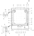
- FIG. 1 is a view showing an example of a laundry treatment apparatus according to the present invention.
- the laundry treatment apparatus may include a cabinet 10 defining the external appearance thereof, a tub 20 provided in the cabinet 10 for receiving wash water, and a drum 30 rotatably provided in the tub 20 for receiving laundry.
- the axis of rotation of the drum 30 may be perpendicular to the lower surface of the cabinet 10 .
- the laundry treatment apparatus may further include a cabinet opening 12 formed in the top of the cabinet 10 for allowing laundry to be introduced or withdrawn therethrough and a door 11 hingedly provided at the top of the cabinet 10 for opening and closing the cabinet opening 12 .
- the laundry treatment apparatus may further include a tub opening 21 formed in the top of the tub 20 for allowing laundry to be introduced or withdrawn therethrough.
- the laundry treatment apparatus may further include a drum opening (not shown) formed in the drum 30 for allowing laundry to be introduced or withdrawn therethrough via the cabinet opening 12 and the tub opening 21 .
- a user may open the door 11 , which is hingedly provided at the top of the cabinet 10 , and may introduce laundry into the drum 30 through the cabinet opening 12 , the tub opening 21 , and the drum opening (not shown) in that order.
- the laundry treatment apparatus may further include a water supply unit 70 for supplying water to the tub 20 and a drainage unit 60 for draining wash water from the tub 20 .
- the water supply unit 70 may include a water supply hose 71 and a water supply valve 73 .
- One end of the water supply hose 71 may protrude outward from the cabinet 10 to receive water from outside, and the other end of the water supply hose 71 may communicate with one side of the tub 20 to supply the water supplied from outside to the tub 20 .
- the water supply valve 73 may be provided in the water supply hose 71 to control the amount of water that is supplied to the tub 20 from the water supply hose 71 .
- the drainage unit 60 may include a drainage hose 61 and a drainage valve 63 .
- One end of the drainage hose 61 may communicate with the tub 20 to drain wash water from the tub 20 , and the other end of the drainage hose 61 may protrude outward from the cabinet 10 to discharge the wash water drained from the tub 20 out of the laundry treatment apparatus.
- the drainage valve 63 may be provided in the drainage hose 61 to control the amount of wash water that is discharged out of the laundry treatment apparatus from the drainage hose 61 .
- the drum 30 is rotatably provided.
- the laundry treatment apparatus according to the present invention may include a power unit 40 for rotating the drum 30 .
- the power unit 40 may include a shaft 43 communicating with the drum 30 for transmitting a rotational force from the power unit 40 to the drum 30 , a stator 45 for generating a rotating magnetic field necessary to rotate the shaft 43 , a rotor 47 rotatably provided on the outer circumferential surface of the stator 45 so as to be rotatable integrally with the shaft 43 , and a bearing housing 43 for rotatably supporting the shaft 43 .
- the power unit 40 may be a direct-drive type power unit, in which the power unit 40 is directly connected to one surface of the drum 30 to directly drive the drum 30 .
- the shaft 43 may be perpendicular to the lower surface of the cabinet 10 .
- a BLDC motor which is commonly used in the technical field related to the laundry treatment apparatus, may be used as the power unit 40 .
- the BLDC motor is well known, and therefore a detailed description thereof will be omitted.
- vibration generated from the drum 30 may be transmitted to the tub 20 , and the vibration transmitted to the tub 20 may be transmitted to the cabinet.
- the tub 20 When the tub 20 vibrates, the tub 20 may be displaced in the leftward-rightward direction or in the upward-downward direction. As a result, the tub 20 may interfere with the cabinet 10 , whereby noise may be generated or the tub may be damaged.
- the laundry treatment apparatus may include a vibration unit for preventing the vibration of the tub 20 from being transmitted to the cabinet 10 .
- the vibration unit may include a first holder 51 provided at one surface of the cabinet 10 , a second holder 53 provided at one surface of the tub 20 , a connection unit 55 for connecting the first holder 51 and the second holder 53 , and an elastic member 57 provided at one end of the connection unit 55 for providing an elastic force to the second holder 53 and the connection unit 55 .
- connection unit 55 may include a first fixing part 551 , provided at the other end of the connection unit 55 for preventing the connection unit 55 from being separated from the first holder 51 , and a second fixing part 553 , provided at one end of the connection unit 55 for preventing the connection unit 55 from being separated from the second holder 53 .
- the laundry treatment apparatus may include balancers 31 and 32 provided at at least one of the upper and lower parts of the drum 30 for preventing laundry received in the drum 30 from being unbalanced during the rotation of the drum 30 .
- the upper balancer 31 may be provided at the upper part of the drum 30
- the lower balancer 32 may be provided at the lower part of the drum 30 .
- a conventional ball balancer or fluid balancer is configured such that, when laundry received in the drum 30 shakes, balls or fluid move passively in the opposite direction to solve unbalance, as previously described.
- the balancers 31 and 32 may effectively solve unbalance in a transient state as well as in a steady state.
- the laundry treatment apparatus may include active balancers 31 and 32 for sensing the vibration state of the drum 30 or the tub 20 to determine the position at which unbalance occurs and supplying water in the opposite direction to actively solve unbalance.
- the active balancers 31 and 32 are provided respectively at the upper and lower parts of the drum 30 , however, material costs may be increased and production efficiency may be reduced. For this reason, the active balancer 31 or 32 may be provided at one of the upper and lower part of the drum 30 , and a conventional ball balancer or fluid balancer may be provided at the other.
- the laundry treatment apparatus may further include a sensor unit for sensing the vibration state of the tub 20 or the drum 30 in order to solve unbalance.
- the sensor unit may include a top sensor 81 provided at the top of the tub 20 for sensing the upward-downward vibration of the tub 20 , an upper sensor 83 provided at the upper part of the side of the tub 20 for sensing the leftward-rightward vibration of the upper part of the tub 20 , and a lower sensor 85 provided at the lower part of the side of the tub 20 for sensing the leftward-rightward vibration of the lower part of the tub 20 .
- the sensors of the sensor unit may be optical sensors.
- the top sensor 81 , the upper sensor 83 , and the lower sensor 85 may sense the upward-downward distance between the top of the tub 20 and the top of the cabinet 10 , the leftward-rightward distance between the upper part of the side of the tub 20 and the upper part of the side of the cabinet 10 , and the leftward-rightward distance between the lower part of the side of the tub 20 and the lower part of the side of the cabinet 10 , respectively, in real time to derive sinusoidal profiles.
- FIG. 2 is a view showing an example of the sensor unit provided in the present invention.
- the laundry treatment apparatus may include a top sensor 81 provided at the top of the tub 20 for measuring the distance YC from the top of the tub 20 to the top of the cabinet 10 .
- the laundry treatment apparatus may include an upper sensor 83 provided at the upper part of the side of the tub 20 for measuring the distance YT from the upper part of the side of the tub 20 to the upper part of the side of the cabinet 10 .
- the laundry treatment apparatus may include a lower sensor 85 provided at the lower part of the side of the tub 20 for measuring the distance YB from the lower part of the side of the tub 20 to the lower part of the side of the cabinet 10 .
- the top sensor 81 , the upper sensor 83 , and the lower sensor 85 may be optical sensors.
- the top sensor 81 senses the upward-downward vibration of the tub 20
- the upper sensor 83 and the lower sensor 85 sense the leftward-rightward vibration of the tub 20 .
- the upper sensor 83 and the lower sensor 85 sense the leftward-rightward vibration of the tub 20 , it is possible to sense the position of laundry causing unbalance using only one of the upper and lower sensors.
- the upper sensor 83 and the lower sensor 85 may be provided at the upper part and the lower part of the side of the tub 20 , respectively.
- FIG. 3 is a view showing an example of the upper balancer provided in the present invention.
- the laundry treatment apparatus may include a hollow upper balancer 31 for solving unbalance occurring at the upper part of the drum 30 .
- the upper balancer 31 is configured to surround the upper part of the drum 30 . Since laundry can be introduced into or withdrawn from the drum 30 , the upper balancer 31 may have a hollow shape having an opening formed in the center thereof.
- the upper balancer 31 may include an upper housing 311 defining a space for receiving water necessary to solve unbalance, a first partition unit 313 provided in the upper housing 311 , a first water supply unit 315 for supplying water into the upper housing 311 to solve unbalance, and a first drainage unit 317 for draining the water from the upper housing 311 after the unbalance is solved.
- the upper housing 311 may include a first upper housing 3111 defining the inner circumferential surface of the upper balancer 31 and a second upper housing 3113 defining the outer circumferential surface of the upper balancer 31 .
- the section of the first upper housing 3111 may be formed in the vertical direction so as to define the inner circumferential surface of the upper balancer 31
- the section of the second upper housing 3113 may be formed so as to define the lower surface, the outer circumferential surface, and the upper surface of the upper balancer 31 .
- the upper surface of the second upper housing 3113 may be spaced apart from the first upper housing 3111 by a predetermined distance. Consequently, an upper inlet 319 is formed between the upper surface of the second upper housing 3113 and the first upper housing 3111 .
- the upper inlet is formed to provide a channel for supplying water to the upper balancer 31 in order to solve unbalance.
- a water supply channel may be defined by the upper inlet 319 .
- the shape of the first upper housing 3111 and the second upper housing 3113 is not limited to that shown in FIG. 3 , as long as the channel for supplying water to the upper balancer 31 is provided, as described above.
- the shape of the first water supply unit 315 is not limited to that shown in FIG. 3 as long as water can be supplied into the upper housing 311 .
- the first drainage unit 317 may be provided at the lower end of the first upper housing 3111 .
- a plurality of first partition units 313 may be provided in the upper housing 311 to partition the interior of the upper housing 311 .
- water may be supplied in the direction opposite the position of laundry during the rotation of the drum 30 in order to solve unbalance occurring in the drum 30 .
- the unbalance is solved during the rotation of the drum 30 , the rotation of the drum 30 is stopped, and the water is drained from the upper housing 311 in the state in which the drum 30 is stopped.
- the first drainage unit 317 may be provided at the lower part of the inside of the upper housing 311 , i.e. the lower part of the first upper housing 3111 . That is, the first drainage unit 317 may be configured to drain the water received in the upper housing 311 in a direction that is perpendicular to the direction of gravity.
- the water in the upper housing 311 may solve unbalance without being drained due to the centrifugal force during the rotation of the drum 30 .
- the rotation of the drum 30 may be stopped, and the water in the upper housing 311 may be drained into the drum through the first drainage unit 317 .
- a plurality of first partition units 313 may be provided in the upper housing 311 to partition the interior of the upper housing 311 .
- the interior of the upper housing 311 is partitioned into 8 spaces by the first partition units 313 .
- the number of spaces into which the upper housing 311 is partitioned by the first partition units 313 is not limited thereto.
- the number of first partition units 313 may be changed as needed as long as unbalance is solved.
- water may be supplied in the direction opposite the position of laundry in the state in which the drum 30 is temporarily stopped in order to solve unbalance occurring in the drum 30 .
- Second unbalance may occur with the result that noise may be generated in the laundry treatment apparatus.
- the water may be drained from the upper housing 311 during the rotation of the drum 30 or in the state in which the drum is stopped again.
- the laundry treatment apparatus may be configured such that water is continuously supplied into the upper housing 311 after the unbalance is solved, and when the water is supplied up to a predetermined height, a siphon phenomenon, in which the water in the upper housing 311 is drained all at once, occurs.
- the first drainage unit 317 may include a hole 3175 for allowing communication between the opening formed in the center of the upper balancer 31 and the interior of the upper balancer 31 , a first inner wall 3173 communicating with the opening formed in the center of the upper balancer 31 via the hole 3175 , the first inner wall 3173 defining a pipe-shaped inner wall, and a first outer wall part 3171 formed so as to surround the first inner wall 3173 in the state of being spaced apart from the first inner wall 3173 , the first outer wall part 3171 defining a pipe-shaped outer wall.
- the water supplied into the upper housing 311 When the water supplied into the upper housing 311 reaches a predetermined height hp, the water may be discharged through the space between the first inner wall 3173 and the first outer wall part 3171 , the space defined in the first inner wall 3173 , and the hole 3175 .
- the water supplied into the upper housing 311 when the water supplied into the upper housing 311 starts to be discharged, the water supplied into the upper housing 311 may be entirely discharged outside due to the difference between the pressure in the first inner wall 3173 and the pressure in the upper balancer 31 . That is, the water in the upper housing 311 is drained all at once according to a siphon phenomenon.
- FIGS. 4, 5, and 6 are views showing an example of the lower balancer provided in the present invention.
- the laundry treatment apparatus may include a hollow lower balancer 32 for solving unbalance occurring at the lower part of the drum 30 .
- the laundry treatment apparatus may further include a power unit 40 for rotating the drum 30 .
- the power unit 40 may be provided at the bottom of the drum 30 .
- the lower balancer 32 may have a hollow shape having an opening formed in the center thereof.
- the lower balancer 32 may include a lower housing 321 defining a space for receiving water necessary to solve unbalance, a second partition unit 323 provided in the lower housing 321 , a second water supply unit 325 for supplying water into the lower housing 321 to solve unbalance, and a second drainage unit 327 for draining the water from the lower housing 321 after the unbalance is solved.
- the lower housing 321 may include a first lower housing 3211 defining the inner circumferential surface of the lower balancer 32 and a second lower housing 3213 defining the outer circumferential surface of the lower balancer 32 .
- the section of the first lower housing 3211 may be formed in the vertical direction so as to define the inner circumferential surface of the lower balancer 32
- the section of the second lower housing 3213 may be formed so as to define the lower surface, the outer circumferential surface, and the upper surface of the lower balancer 32 .
- the upper surface of the second lower housing 3213 may be spaced apart from the first lower housing 3211 by a predetermined distance. Consequently, a lower inlet 329 is formed between the upper surface of the second lower housing 3213 and the first lower housing 3211 .
- the lower inlet is formed to provide a channel for supplying water to the lower balancer 32 in order to solve unbalance.
- a water supply channel may be defined by the lower inlet 329 .
- the shape of the first lower housing 3211 and the second lower housing 3213 is not limited to that shown in FIG. 4 , as long as the channel for supplying water to the lower balancer 32 is provided, as described above.
- the shape of the second water supply unit 325 is not limited to that shown in FIG. 4 , as long as water can be supplied into the lower housing 321 without stopping the rotation of the drum 30 in the state in which the drum 30 is rotated.
- the second drainage unit 327 may be provided at the lower end of the first lower housing 3211 .
- water may be supplied in the direction opposite the position of laundry in the state in which the drum 30 is temporarily stopped in order to solve unbalance occurring in the drum 30 , as previously described.
- the second drainage unit 327 may be provided at the lower part of the inside of the lower housing 321 , i.e. the lower part of the first lower housing 3211 .
- the second drainage unit 327 may include a hole 3275 for allowing communication between the opening formed in the center of the lower balancer 32 and the interior of the lower balancer 32 , a second inner wall 3273 communicating with the opening formed in the center of the lower balancer via the hole 3275 , the second inner wall 3273 defining a pipe-shaped inner wall, and a second outer wall part 3271 formed so as to surround the second inner wall 3273 in the state of being spaced apart from the second inner wall 3273 , the second outer wall part 3271 defining a pipe-shaped outer wall.
- the second drainage unit 327 drains the water in the lower housing 321 according to a siphon phenomenon in the same manner as in the first drainage unit shown in FIGS. 3( b ) and 3( c ) .
- the second drainage unit 327 may be configured to drain the water received in the lower housing 321 in the direction of gravity.
- a plurality of second partition units 323 may be provided in the lower housing 321 to partition the interior of the lower housing 321 .
- the second partition units 323 may extend in a direction that is perpendicular to the direction of gravity to partition the interior of the lower housing 321 .
- the interior of the lower housing 321 is partitioned into 8 spaces by the second partition units 323 .
- the number of spaces into which the lower housing 321 is partitioned by the second partition units 323 is not limited thereto.
- the number of second partition units 323 may be changed as needed as long as unbalance is solved.
- the second partition units 323 provided in the lower balancer 32 will now be described with reference to FIG. 6 .
- FIG. 6 there is shown only the structure of the second partition units 323 provided in the lower balancer 32 ; however, this structure may equally apply to the upper balancer 31 .
- the second partition units 323 may include second main partitions 3231 for partitioning the interior of the lower housing 321 into a plurality of spaces and at least one second sub partition 3233 provided in each partitioned space.
- each of the upper balance 31 and the lower balancer 32 of the laundry treatment apparatus according to the present invention may include one or more second sub partitions 3233 provided between the respective second main partitions 3231 so as to have different heights.
- the heights of the second sub partitions 3233 may be sequentially increased in the rotational direction of the drum 30 .
- FIG. 6 for example, there is shown an embodiment in which one second main partition 3231 and four second sub partitions 3233 are provided.
- the four second sub partitions 3233 may have heights B 5 , B 4 , B 3 , and B 2 , which are sequentially increased, and the second main partition 3231 may have a height B 1 , which is the highest.
- second sub partitions 3233 is not limited thereto, and may be changed as needed.
- the second main partitions 3231 are configured to partition the lower housing 321 .
- the second sub partitions 3233 are configured not to partition the lower housing 321 , since the second sub partitions 3233 are provided to prevent a phenomenon in which the water in the lower housing 321 is biased, as previously described.
- the second sub partitions 3233 are configured such that the water in the lower housing 321 can freely move between the respective second sub partitions 3233 .
- the length of the lower surface of each second sub partition 3233 may be shorter than the length of the lower surface of each second main partition 3231 by A in the diametrical direction.
- each second main partition 3231 the difference between the length of the lower surface of each second main partition 3231 and the length of the lower surface of each second sub partition 3233 may be changed as needed. Consequently, the length difference is not limited to the ratio shown in FIG. 6 .
- FIG. 7 is a view showing an example of a method of controlling unbalance occurring in the laundry treatment apparatus according to the present invention.
- unbalance means the case in which mass distribution is not uniform in the circumferential direction of the drum 30 on the basis of the axis of rotation of the drum 30 during the rotation of the drum 30 , which may mean that the drum 30 is rotated in the state in which laundry in the drum 30 is biased.
- the position at which laundry is biased is determined, and water is sprayed in the direction opposite the position at which the laundry is positioned on the basis of the axis of rotation of the drum 30 to solve unbalance. Since the laundry has its own mass and rotates together with the drum 30 , an inertia error ⁇ 1 due to the inertia thereof is generated when primary control is performed, as shown in FIG. 7( a ) .
- Counter electromotive force is electromotive force that is generated in an armature of a motor or a primary coil in a transformer in a direction opposite the direction in which electromotive force is generated in a power source.
- the secondary control is performed in the opposite direction in order to compensate for the inertia error ⁇ 1 , but the counter electromotive force error ⁇ 2 is generated due to the counter electromotive force.
- tertiary control may be performed for more accurate control, as shown in FIG. 7( c ) .
- the tertiary control may be performed to control the balancers 31 and 32 in the state of reflecting the counter electromotive force error ⁇ 2 generated when the secondary control is performed.
- a residual error ⁇ 3 may be generated when the above control is performed. If the residual error ⁇ 3 is within a range of predetermined allowable error m ⁇ , it is possible to efficiently solve unbalance.
- FIG. 8 is a flowchart showing an example of a control method of deciding the amount of water that is supplied to the upper balancer and the lower balancer provided in the laundry treatment apparatus according to the present invention and the position of the upper balancer and the lower balancer to which the water is supplied.
- the control method of the laundry treatment apparatus may include a distance measurement step (S 10 ) of measuring an upper distance YT and a lower distance YB using the upper sensor 83 and the lower sensor 85 , respectively, and a measurement comparison step (S 20 ) of determining whether the upper distance YT and the lower distance YB, measured at the distance measurement step (S 10 ), are equal to each other.
- the control method of the laundry treatment apparatus may include a lower amplitude measurement step (S 30 ) of measuring the amplitude of the lower distance YB from the profile of the lower distance YB and a lower phase measurement step (S 40 ) of measuring the phase of the lower distance YB.
- the control method of the laundry treatment apparatus may further include a lower water supply amount decision step (S 31 ) of deciding the amount of water to be supplied to the lower balancer 32 based on the amplitude of the lower distance YB, measured at the lower amplitude measurement step (S 30 ), and a first lower water supply position decision step (S 41 ) of deciding the position of the lower balancer to which water is to be supplied based on the phase of the lower distance YB.
- a first lower balancer water supply step (S 50 ) of supplying water to the lower balancer 32 based on the water supply amount and the water supply position, decided at the lower water supply amount decision step (S 31 ) and the lower water supply position decision step (S 41 ), may be performed to solve unbalance.
- water may be supplied to both the upper balancer 31 and the lower balancer 32 to solve unbalance.
- water is supplied to both the upper balancer 31 and the lower balancer 32 , unlike the first lower balancer water supply step (S 50 ). Since the upper balancer 31 and the lower balancer 32 are provided at the upper part and the lower part of the drum 30 so as to be rotatable integrally with the drum 30 , these balancers are coupled to each other. In the case in which water is supplied merely based on the amplitudes and phases of the profiles of the upper distance YT and the lower distance YB, therefore, unbalance is not solved.
- phase of the profile of the upper distance YT, used to control the upper balancer 31 must be applied to control the lower balancer 32 .
- the control method may include an upper amplitude measurement step (S 60 ) of measuring the amplitude of the upper distance YT, an upper water supply amount decision step (S 61 ) of deciding the amount of water to be supplied to the upper balancer 31 based on the measured amplitude of the upper distance, an upper phase measurement step (S 70 ) of measuring the phase of the upper distance YT, an upper water supply position decision step (S 71 ) of deciding the position of the upper balancer 31 to which water is to be supplied based on the measured phase of the upper distance, and an upper balancer water supply step (S 80 ) of supplying the amount of water to be supplied, decided at the upper water supply amount decision step (S 61 ), to the water supply position, decided at the upper water supply position decision step (S 71 ).
- control method may further include a lower balancer water supply amount decision step (S 31 ) of deciding the amount of water to be supplied to the lower balancer based on the amplitude of the lower distance YB, measured at the lower amplitude measurement step (S 30 ) of measuring the amplitude of the lower distance, a phase difference calculation step (S 90 ) of calculating the difference between the phase of the lower distance, measured at the lower phase measurement step (S 40 ) of measuring the phase of the lower distance, and the phase of the upper distance, measured at the upper phase measurement step (S 70 ) of measuring the phase of the upper distance, a second lower water supply position decision step (S 91 ) of deciding the position of the lower balancer to which water is to be supplied using the difference between the phase of the upper distance and the phase of the lower distance, calculated at the phase difference calculation step (S 90 ), and a second lower balancer water supply step (S 51 ) of supplying the amount of water to be supplied, decided at the lower water supply amount decision step (S 31 ),
- FIGS. 9 and 10 are views showing an example of water supply units provided in the upper balancer and the lower balancer for supplying water thereto.
- the laundry treatment apparatus may further include a first water supply unit 315 for supplying water to the upper balancer 31 in the state in which the drum 30 is stopped.
- the first water supply unit 315 may include a first water supply hose 3153 for supplying water into the upper balancer 31 in the state in which the drum 30 is stopped, a first water supply guide 3151 for guiding the water from the first water supply hose 3153 into the upper housing 311 , and a first water supply valve 3155 for controlling the amount of water that is supplied from the first water supply hose 3153 .
- the water from the first water supply unit 315 moves into the upper housing 311 .
- the upper housing 311 may include a first upper housing 3111 and a second upper housing 3113 , which are spaced apart from each other by a predetermined distance, and the water from the first water supply unit 315 may be supplied into the upper housing 311 through a channel defined between the first upper housing 3111 and the second upper housing 3113 .
- the first water supply unit 315 may be provided separately, or may be provided at the water supply unit 70 . Furthermore, the first water supply unit 315 may communicate with a branch pipe (not shown) diverging from the water supply unit 70 .
- the laundry treatment apparatus may further include a second water supply unit 325 for supplying water to the lower balancer 32 in the state in which the drum 30 is stopped.
- the second water supply unit 325 may include a second water supply hose 3253 for supplying water into the lower balancer 32 in the state in which the drum 30 is stopped, a second water supply guide 3251 for guiding the water from the second water supply hose 3253 into the lower housing 321 , and a second water supply valve 3255 for controlling the amount of water that is supplied from the second water supply hose 3253 .
- the water from the second water supply unit 325 moves into the lower housing 321 .
- the lower housing 321 may include a first lower housing 3211 and a second lower housing 3213 , which are spaced apart from each other by a predetermined distance, and the water from the second water supply unit 325 may be supplied into the lower housing 321 through a channel defined between the first lower housing 3211 and the second lower housing 3213 .
Landscapes
- Engineering & Computer Science (AREA)
- Textile Engineering (AREA)
- General Engineering & Computer Science (AREA)
- Physics & Mathematics (AREA)
- Acoustics & Sound (AREA)
- Aviation & Aerospace Engineering (AREA)
- Mechanical Engineering (AREA)
- Main Body Construction Of Washing Machines And Laundry Dryers (AREA)
- Control Of Washing Machine And Dryer (AREA)
- Detail Structures Of Washing Machines And Dryers (AREA)
Abstract
Description
Claims (20)
Applications Claiming Priority (3)
| Application Number | Priority Date | Filing Date | Title |
|---|---|---|---|
| KR10-2015-0029767 | 2015-03-03 | ||
| KR1020150029767A KR102326699B1 (en) | 2015-03-03 | 2015-03-03 | Laundry Treating Apparatus |
| PCT/KR2016/002136 WO2016140531A1 (en) | 2015-03-03 | 2016-03-03 | Clothing treatment device |
Publications (2)
| Publication Number | Publication Date |
|---|---|
| US20180087207A1 US20180087207A1 (en) | 2018-03-29 |
| US10612176B2 true US10612176B2 (en) | 2020-04-07 |
Family
ID=56848378
Family Applications (1)
| Application Number | Title | Priority Date | Filing Date |
|---|---|---|---|
| US15/554,945 Active 2037-02-01 US10612176B2 (en) | 2015-03-03 | 2016-03-03 | Clothing treatment device |
Country Status (3)
| Country | Link |
|---|---|
| US (1) | US10612176B2 (en) |
| KR (1) | KR102326699B1 (en) |
| WO (1) | WO2016140531A1 (en) |
Families Citing this family (4)
| Publication number | Priority date | Publication date | Assignee | Title |
|---|---|---|---|---|
| CN207619674U (en) * | 2016-12-01 | 2018-07-17 | 青岛海尔洗衣机有限公司 | A kind of interior bucket bottom gimbals structure |
| CN107488983B (en) * | 2017-09-27 | 2022-04-26 | 天津海尔洗涤电器有限公司 | Self-adjusting balance ring and washing machine |
| KR102627707B1 (en) * | 2018-11-30 | 2024-01-23 | 삼성전자주식회사 | Clothes care apparatus and control method thereof |
| CN111826895B (en) * | 2019-04-19 | 2021-11-23 | 广东美的白色家电技术创新中心有限公司 | Rotary balancing device and clothes treatment equipment |
Citations (8)
| Publication number | Priority date | Publication date | Assignee | Title |
|---|---|---|---|---|
| CN2357030Y (en) | 1998-12-04 | 2000-01-05 | 魏明哲 | Centrifugal automatic balancer |
| KR20010010616A (en) | 1999-07-21 | 2001-02-15 | 전주범 | feed water device with shower-water supply and balancing function in washing machine |
| KR100296285B1 (en) | 1998-04-15 | 2001-08-07 | 구자홍 | Balancer for washing machine |
| KR20050050262A (en) | 2003-11-25 | 2005-05-31 | 주식회사 대우일렉트로닉스 | Balancing mechanism of washing machine |
| KR20130080222A (en) | 2012-01-04 | 2013-07-12 | 삼성전자주식회사 | Washing machine |
| US20130233028A1 (en) * | 2012-03-12 | 2013-09-12 | General Electric Company | Balance ring for an appliance |
| US20130312464A1 (en) * | 2012-05-22 | 2013-11-28 | General Electric Company | Balance ring with features to control fluid distribution |
| US20130319056A1 (en) * | 2012-06-05 | 2013-12-05 | Lg Electronics Inc. | Washing machine |
-
2015
- 2015-03-03 KR KR1020150029767A patent/KR102326699B1/en active Active
-
2016
- 2016-03-03 WO PCT/KR2016/002136 patent/WO2016140531A1/en not_active Ceased
- 2016-03-03 US US15/554,945 patent/US10612176B2/en active Active
Patent Citations (8)
| Publication number | Priority date | Publication date | Assignee | Title |
|---|---|---|---|---|
| KR100296285B1 (en) | 1998-04-15 | 2001-08-07 | 구자홍 | Balancer for washing machine |
| CN2357030Y (en) | 1998-12-04 | 2000-01-05 | 魏明哲 | Centrifugal automatic balancer |
| KR20010010616A (en) | 1999-07-21 | 2001-02-15 | 전주범 | feed water device with shower-water supply and balancing function in washing machine |
| KR20050050262A (en) | 2003-11-25 | 2005-05-31 | 주식회사 대우일렉트로닉스 | Balancing mechanism of washing machine |
| KR20130080222A (en) | 2012-01-04 | 2013-07-12 | 삼성전자주식회사 | Washing machine |
| US20130233028A1 (en) * | 2012-03-12 | 2013-09-12 | General Electric Company | Balance ring for an appliance |
| US20130312464A1 (en) * | 2012-05-22 | 2013-11-28 | General Electric Company | Balance ring with features to control fluid distribution |
| US20130319056A1 (en) * | 2012-06-05 | 2013-12-05 | Lg Electronics Inc. | Washing machine |
Non-Patent Citations (3)
| Title |
|---|
| International Search Report dated Apr. 29, 2016 issued in Application No. PCT/KR2016/002136 (with English Translation). |
| Wei, "CN2357030 English Machine Translation.pdf", Jan. 5, 2000-Machine translation from Espacenet.com. * |
| Wei, "CN2357030 English Machine Translation.pdf", Jan. 5, 2000—Machine translation from Espacenet.com. * |
Also Published As
| Publication number | Publication date |
|---|---|
| US20180087207A1 (en) | 2018-03-29 |
| WO2016140531A1 (en) | 2016-09-09 |
| KR102326699B1 (en) | 2021-11-16 |
| KR20160106966A (en) | 2016-09-13 |
Similar Documents
| Publication | Publication Date | Title |
|---|---|---|
| EP3108053B1 (en) | Laundry treating apparatus | |
| RU2617361C2 (en) | Washing processing machine | |
| US10689787B2 (en) | Washing machine and method for controlling the same | |
| US9624616B2 (en) | Laundry treatment apparatus | |
| US10612176B2 (en) | Clothing treatment device | |
| US10273621B2 (en) | Laundry treating appliance and methods of operation | |
| JP2010207316A (en) | Washing machine | |
| US11661695B2 (en) | Laundry apparatuses having dynamic balancing assemblies | |
| KR102306752B1 (en) | Laundry Treating Apparatus | |
| US11697900B2 (en) | Suspensionless laundry apparatuses and methods of balancing a laundry apparatus | |
| US10920355B2 (en) | Garment processing apparatus and method of controlling garment processing apparatus | |
| US11655579B2 (en) | Dynamic balancing assemblies and laundry apparatuses having one or more clocksprings | |
| AU2019372914B2 (en) | Laundry processing device and control method therefor | |
| US10697107B2 (en) | Clothing processing apparatus and control method of clothing processing apparatus | |
| KR20230172686A (en) | Washing apparutus and controlling method thereof | |
| KR20210003493A (en) | Control Method for Laundry Treatment Machine |
Legal Events
| Date | Code | Title | Description |
|---|---|---|---|
| AS | Assignment |
Owner name: LG ELECTRONICS INC., KOREA, REPUBLIC OF Free format text: ASSIGNMENT OF ASSIGNORS INTEREST;ASSIGNORS:CHOI, KAHYUNG;KIM, YOUNGHO;REEL/FRAME:043465/0046 Effective date: 20170829 |
|
| FEPP | Fee payment procedure |
Free format text: ENTITY STATUS SET TO UNDISCOUNTED (ORIGINAL EVENT CODE: BIG.); ENTITY STATUS OF PATENT OWNER: LARGE ENTITY |
|
| STPP | Information on status: patent application and granting procedure in general |
Free format text: DOCKETED NEW CASE - READY FOR EXAMINATION |
|
| STPP | Information on status: patent application and granting procedure in general |
Free format text: NON FINAL ACTION MAILED |
|
| STPP | Information on status: patent application and granting procedure in general |
Free format text: RESPONSE TO NON-FINAL OFFICE ACTION ENTERED AND FORWARDED TO EXAMINER |
|
| STPP | Information on status: patent application and granting procedure in general |
Free format text: NOTICE OF ALLOWANCE MAILED -- APPLICATION RECEIVED IN OFFICE OF PUBLICATIONS |
|
| STPP | Information on status: patent application and granting procedure in general |
Free format text: PUBLICATIONS -- ISSUE FEE PAYMENT RECEIVED |
|
| STCF | Information on status: patent grant |
Free format text: PATENTED CASE |
|
| MAFP | Maintenance fee payment |
Free format text: PAYMENT OF MAINTENANCE FEE, 4TH YEAR, LARGE ENTITY (ORIGINAL EVENT CODE: M1551); ENTITY STATUS OF PATENT OWNER: LARGE ENTITY Year of fee payment: 4 |