US1060861A - Support. - Google Patents
Support. Download PDFInfo
- Publication number
- US1060861A US1060861A US58838410A US1910588384A US1060861A US 1060861 A US1060861 A US 1060861A US 58838410 A US58838410 A US 58838410A US 1910588384 A US1910588384 A US 1910588384A US 1060861 A US1060861 A US 1060861A
- Authority
- US
- United States
- Prior art keywords
- leg
- standard
- leg members
- support
- extended
- Prior art date
- Legal status (The legal status is an assumption and is not a legal conclusion. Google has not performed a legal analysis and makes no representation as to the accuracy of the status listed.)
- Expired - Lifetime
Links
- 210000005069 ears Anatomy 0.000 description 2
- 210000003141 lower extremity Anatomy 0.000 description 2
- 230000001154 acute effect Effects 0.000 description 1
- 238000005266 casting Methods 0.000 description 1
- 238000003754 machining Methods 0.000 description 1
- 210000003813 thumb Anatomy 0.000 description 1
Images
Classifications
-
- G—PHYSICS
- G10—MUSICAL INSTRUMENTS; ACOUSTICS
- G10G—REPRESENTATION OF MUSIC; RECORDING MUSIC IN NOTATION FORM; ACCESSORIES FOR MUSIC OR MUSICAL INSTRUMENTS NOT OTHERWISE PROVIDED FOR, e.g. SUPPORTS
- G10G5/00—Supports for musical instruments
-
- F—MECHANICAL ENGINEERING; LIGHTING; HEATING; WEAPONS; BLASTING
- F16—ENGINEERING ELEMENTS AND UNITS; GENERAL MEASURES FOR PRODUCING AND MAINTAINING EFFECTIVE FUNCTIONING OF MACHINES OR INSTALLATIONS; THERMAL INSULATION IN GENERAL
- F16M—FRAMES, CASINGS OR BEDS OF ENGINES, MACHINES OR APPARATUS, NOT SPECIFIC TO ENGINES, MACHINES OR APPARATUS PROVIDED FOR ELSEWHERE; STANDS; SUPPORTS
- F16M11/00—Stands or trestles as supports for apparatus or articles placed thereon ; Stands for scientific apparatus such as gravitational force meters
- F16M11/20—Undercarriages with or without wheels
- F16M11/22—Undercarriages with or without wheels with approximately constant height, e.g. with constant length of column or of legs
Definitions
- This invention relates to supports or stands, and is adapted to a wide range of uses, but I illustrate it in the present case as embodied in a support for the use of inspectors of weights and measures, the stand being provided with a hook, from which balances, spring balances and the like may be suspended.
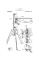
- a rigid yet light, compact and readily portable device is required, and these desirable qualities are embodied in the structure illustrated in the drawings, wherein Figure 1 is a perspective view of the support as it appears when set up; Fig. 2 represents the support folded, certain parts being broken away to show the clamp screw; Fig. 3 is a detail elevation of the locking mechanism partly sectioned to show the hinge and clamp screw; Fig. 4 is a side elevation of the same; and Fig. 5 is a section on the line ee of Fig. 3.
- l represents the upright or standard of the support, which in a stand arranged for the purpose above described, terminates at its upper. end in a hook 2.
- the lower extremity of the standard 1 has a lateral projection 3 extending preferably in the same direction as the hook 2 and terminating in a bifurcated hinge portion 4 provided with a hinge pin 5.
- the hinge pin 5 engages the upper end of a leg member 6 which in turn is hinged by means of the hinge pin 7 and the lugs 8 to two similar leg members 9 and 10 having lugs 11.
- the center lines of the leg members 6, 9 and 10 are at equal acute angles with the center line of the hinge pin 7 and it results that these leg members may be folded fiat upon each other or extended to form a tripod, the stops 12 formed on the lugs 8 of the leg 6 serving to limit the movement of legs 9 and 10 away from leg 6, as clearly illustrated in Fig. 1.
- hinge pin 7 and the standard 1 extends upward from a point near the center of the tripod formed by the leg portions.
- leg portions 9 and 10 are each pro vided with a beveled ear 13 and when these leg portions are bearing against the lugs 12, the beveled faces of these ears are engaged by a similarly beveled lug 1& formed on the lower extremity of the standard 1, when the standard is raised or in its vertical position. In this manner any tendency to force the lug 1 1- downward will hold the legs 9 and 10 extended, pressing them firmly against the stops 12,
- the leg portions may be rigidly held in place by clamping the standard 1 to the lug 8 of the leg portion 6 and such clamping is preferably eifected by a thumb screw 15 passing through a hole 16 in the portion 3 and engaging a threaded hole 17 in the upper lug 8.
- the threaded portion 18 of the screw is larger than its shank 19 and the hole 16 so as to retain the screw in the hole.
- a counter bore 20 permits the complete withdrawal of the screw from the hole 17.
- the stand above described is rigid when set up, folds compactly and has no detached parts to become lost. It can be made from simple castings with very little machining,
- a folding support the combination of a plurality of leg members; a hinge connecting said leg members, the axis of said hinge making approximately equal angles with the center lines of said leg members; a standard hinged to one leg member; a lug carried by the standard and adapted to enter into wedging engagement with the leg members to hold the latter extended when the standard is extended; and a screw engaging the standard and one of said leg members to clamp said standard in extended position.
- leg member a leg member; a pair of similar leg members hinged thereto, the axis of such hinging making approximately equal angles with the several leg members; a leg clamp movably mounted on the first leg member and having a beveled lug adapted to enter into wedging engagement with the other leg members to hold them in extended position; and a screw for forcing said clamp against said leg members.
- a support in a support the combination of a pair of leg members having beveled ear portions; a third leg member having a limit stop to limit the movement of said first two leg members with reference to said third leg member; a hinge pin engaging said three leg members and making approximately equal angles with the center lines thereof; a standard hinged to said third leg member and having a beveled lug to engage said beveled ears to urge their respective leg members against said limit stop; and means for clamping the standard and its lug to the third leg member.
Landscapes
- Engineering & Computer Science (AREA)
- General Engineering & Computer Science (AREA)
- Physics & Mathematics (AREA)
- Acoustics & Sound (AREA)
- Multimedia (AREA)
- Mechanical Engineering (AREA)
- Clamps And Clips (AREA)
Description
Patented May 6, 1913.
I mllmumww.
v er i m E. 1). N. SGHULTE.
SUPPORT.
APPLICATION FILED OCT. 21, 1910.
UNITED STATES PATENT orrron.
EDWARD D. N. SCHULTE, 0F TROY, NEW YORK, ASSIGNOR T0 W. & L. E. GURLEY, A CORPORATION OF NEW YORK.
SUPPORT.
To all whom it may concern Be itknown that I, EDWARD D. N. ScHUL'rE, a citizen of the United States, residing at Troy, in the county of Rensselaer and State of New York, have invented certain new and useful Improvements in Supports, of which the following is a specification.
This invention relates to supports or stands, and is adapted to a wide range of uses, but I illustrate it in the present case as embodied in a support for the use of inspectors of weights and measures, the stand being provided with a hook, from which balances, spring balances and the like may be suspended. For this clas of work a rigid yet light, compact and readily portable device is required, and these desirable qualities are embodied in the structure illustrated in the drawings, wherein Figure 1 is a perspective view of the support as it appears when set up; Fig. 2 represents the support folded, certain parts being broken away to show the clamp screw; Fig. 3 is a detail elevation of the locking mechanism partly sectioned to show the hinge and clamp screw; Fig. 4 is a side elevation of the same; and Fig. 5 is a section on the line ee of Fig. 3.
l represents the upright or standard of the support, which in a stand arranged for the purpose above described, terminates at its upper. end in a hook 2. The lower extremity of the standard 1 has a lateral projection 3 extending preferably in the same direction as the hook 2 and terminating in a bifurcated hinge portion 4 provided with a hinge pin 5. The hinge pin 5 engages the upper end of a leg member 6 which in turn is hinged by means of the hinge pin 7 and the lugs 8 to two similar leg members 9 and 10 having lugs 11. The center lines of the leg members 6, 9 and 10 are at equal acute angles with the center line of the hinge pin 7 and it results that these leg members may be folded fiat upon each other or extended to form a tripod, the stops 12 formed on the lugs 8 of the leg 6 serving to limit the movement of legs 9 and 10 away from leg 6, as clearly illustrated in Fig. 1.
It is apparent from the above that the legs and the standard may be folded upon each other as in Fig. 2 or extended as in Fig. 1. The parts are so proportioned that the projection 3 extends over the top of Specification of Letters Patent.
Application filed October 21, 1.910.
Patented May 6,1913.
Serial No. 588,384.
hinge pin 7 and the standard 1 extends upward from a point near the center of the tripod formed by the leg portions.
The leg portions 9 and 10 are each pro vided with a beveled ear 13 and when these leg portions are bearing against the lugs 12, the beveled faces of these ears are engaged by a similarly beveled lug 1& formed on the lower extremity of the standard 1, when the standard is raised or in its vertical position. In this manner any tendency to force the lug 1 1- downward will hold the legs 9 and 10 extended, pressing them firmly against the stops 12, Thus the leg portions may be rigidly held in place by clamping the standard 1 to the lug 8 of the leg portion 6 and such clamping is preferably eifected by a thumb screw 15 passing through a hole 16 in the portion 3 and engaging a threaded hole 17 in the upper lug 8. The threaded portion 18 of the screw is larger than its shank 19 and the hole 16 so as to retain the screw in the hole. A counter bore 20 permits the complete withdrawal of the screw from the hole 17.
The stand above described is rigid when set up, folds compactly and has no detached parts to become lost. It can be made from simple castings with very little machining,
and due to the wedging engagement of the parts, does not tend to become less rigid through wear.
Having thus described the invention, what I claim as new and desire to secure by Letters Patent is 1. In a folding support the combination of a plurality of leg members; a hinge connecting said leg members, the axis of said hinge making approximately equal angles with the center lines of said leg members; a standard hinged to one leg member; a lug carried by the standard and adapted to enter into wedging engagement with the leg members to hold the latter extended when the standard is extended; and a screw engaging the standard and one of said leg members to clamp said standard in extended position.
2. The combination of a leg member; a pair of similar leg members hinged thereto, the axis of such hinging making approximately equal angles with the several leg members; a leg clamp movably mounted on the first leg member and having a beveled lug adapted to enter into wedging engagement with the other leg members to hold them in extended position; and a screw for forcing said clamp against said leg members.
3. In a support the combination of a pair of leg members having beveled ear portions; a third leg member having a limit stop to limit the movement of said first two leg members with reference to said third leg member; a hinge pin engaging said three leg members and making approximately equal angles with the center lines thereof; a standard hinged to said third leg member and having a beveled lug to engage said beveled ears to urge their respective leg members against said limit stop; and means for clamping the standard and its lug to the third leg member.
4. In a support the combination of a plurality of leg members; a hinge connecting said leg portions, the axis of said hinge making equal angles with said leg members; a standard hinged to one leg member; means carried by said standard to engage the leg members and hold the latter extended When the standard is extended; and clamping means for locking the standard in extended position.
In testimony whereof I have signed my name to this specification in the presence of two subscribing Witnesses.
EDWARD D. N. SCHULTE.
Vitnesses V. S. HOPKINS, A. C. Dnnors.
Copies of this patent may be obtained for five cents each, by addressing the Commissioner of Patents.
Washington, D. C.
Priority Applications (1)
| Application Number | Priority Date | Filing Date | Title |
|---|---|---|---|
| US58838410A US1060861A (en) | 1910-10-21 | 1910-10-21 | Support. |
Applications Claiming Priority (1)
| Application Number | Priority Date | Filing Date | Title |
|---|---|---|---|
| US58838410A US1060861A (en) | 1910-10-21 | 1910-10-21 | Support. |
Publications (1)
| Publication Number | Publication Date |
|---|---|
| US1060861A true US1060861A (en) | 1913-05-06 |
Family
ID=3129108
Family Applications (1)
| Application Number | Title | Priority Date | Filing Date |
|---|---|---|---|
| US58838410A Expired - Lifetime US1060861A (en) | 1910-10-21 | 1910-10-21 | Support. |
Country Status (1)
| Country | Link |
|---|---|
| US (1) | US1060861A (en) |
Cited By (5)
| Publication number | Priority date | Publication date | Assignee | Title |
|---|---|---|---|---|
| US2706609A (en) * | 1953-06-30 | 1955-04-19 | Alvey Ferguson Co | Pedestal-type supporting stand having foldable base legs |
| US5106048A (en) * | 1990-12-20 | 1992-04-21 | Matthew Lebar | Support stands |
| EP1838962A4 (en) * | 2005-01-18 | 2015-04-15 | Owec Tower As | SUPPORT FOR A HIGH MASS |
| US10208889B2 (en) * | 2017-05-29 | 2019-02-19 | Tcg Partners, Llc—Intellectual Property Series | Collapsible three legged platform |
| US10679595B2 (en) * | 2016-10-28 | 2020-06-09 | Sheldon LAVINEWAY | Apparatus for supporting musical instruments |
-
1910
- 1910-10-21 US US58838410A patent/US1060861A/en not_active Expired - Lifetime
Cited By (7)
| Publication number | Priority date | Publication date | Assignee | Title |
|---|---|---|---|---|
| US2706609A (en) * | 1953-06-30 | 1955-04-19 | Alvey Ferguson Co | Pedestal-type supporting stand having foldable base legs |
| US5106048A (en) * | 1990-12-20 | 1992-04-21 | Matthew Lebar | Support stands |
| EP1838962A4 (en) * | 2005-01-18 | 2015-04-15 | Owec Tower As | SUPPORT FOR A HIGH MASS |
| US20190133375A1 (en) * | 2014-10-23 | 2019-05-09 | TCG Partners LLC - Intellectual Property Series | Collapsible Three Legged Platform |
| US10791873B2 (en) * | 2014-10-23 | 2020-10-06 | Tcg Partners, Llc—Intellectual Property Series | Collapsible three legged platform |
| US10679595B2 (en) * | 2016-10-28 | 2020-06-09 | Sheldon LAVINEWAY | Apparatus for supporting musical instruments |
| US10208889B2 (en) * | 2017-05-29 | 2019-02-19 | Tcg Partners, Llc—Intellectual Property Series | Collapsible three legged platform |
Similar Documents
| Publication | Publication Date | Title |
|---|---|---|
| US900552A (en) | Folding table. | |
| US1049642A (en) | Clothes-line fastener. | |
| US979070A (en) | Adjustable support for drawing-boards. | |
| US812660A (en) | Adjustable mirror-support. | |
| US1073013A (en) | Mechanic's candle-holder. | |
| US1874424A (en) | Collapsible bracket | |
| US689707A (en) | Drawing-table. | |
| US821052A (en) | Tripod-stand for cameras. | |
| US1227850A (en) | Folding stand. | |
| US588552A (en) | Tripod | |
| US1061102A (en) | Tripod. | |
| US811166A (en) | Hammock-support. | |
| US940459A (en) | Scaffold-bracket. | |
| US1138088A (en) | Door-clamp. | |
| US654340A (en) | Trousers-hanger. | |
| US939963A (en) | Folding-table. | |
| US660049A (en) | Universal support. | |
| US578886A (en) | Bicycle-stand | |
| US1066668A (en) | Hammock-stand. | |
| US501510A (en) | Camera-tripod hxad | |
| US833167A (en) | Lamp-stand. | |
| US806265A (en) | Awning-fixture. | |
| US312363A (en) | Petefia | |
| US75827A (en) | Jearitm atkins | |
| US726455A (en) | Portable drum-rack. |