US1060606A - Steering-knuckle. - Google Patents
Steering-knuckle. Download PDFInfo
- Publication number
- US1060606A US1060606A US62313111A US1911623131A US1060606A US 1060606 A US1060606 A US 1060606A US 62313111 A US62313111 A US 62313111A US 1911623131 A US1911623131 A US 1911623131A US 1060606 A US1060606 A US 1060606A
- Authority
- US
- United States
- Prior art keywords
- steering
- arm
- post
- knuckle
- enlargement
- Prior art date
- Legal status (The legal status is an assumption and is not a legal conclusion. Google has not performed a legal analysis and makes no representation as to the accuracy of the status listed.)
- Expired - Lifetime
Links
- 238000010276 construction Methods 0.000 description 2
- 230000004888 barrier function Effects 0.000 description 1
- 239000002184 metal Substances 0.000 description 1
Images
Classifications
-
- F—MECHANICAL ENGINEERING; LIGHTING; HEATING; WEAPONS; BLASTING
- F16—ENGINEERING ELEMENTS AND UNITS; GENERAL MEASURES FOR PRODUCING AND MAINTAINING EFFECTIVE FUNCTIONING OF MACHINES OR INSTALLATIONS; THERMAL INSULATION IN GENERAL
- F16H—GEARING
- F16H59/00—Control inputs to control units of change-speed- or reversing-gearings for conveying rotary motion
- F16H59/02—Selector apparatus
- F16H59/04—Ratio selector apparatus
-
- Y—GENERAL TAGGING OF NEW TECHNOLOGICAL DEVELOPMENTS; GENERAL TAGGING OF CROSS-SECTIONAL TECHNOLOGIES SPANNING OVER SEVERAL SECTIONS OF THE IPC; TECHNICAL SUBJECTS COVERED BY FORMER USPC CROSS-REFERENCE ART COLLECTIONS [XRACs] AND DIGESTS
- Y10—TECHNICAL SUBJECTS COVERED BY FORMER USPC
- Y10T—TECHNICAL SUBJECTS COVERED BY FORMER US CLASSIFICATION
- Y10T74/00—Machine element or mechanism
- Y10T74/20—Control lever and linkage systems
- Y10T74/20207—Multiple controlling elements for single controlled element
- Y10T74/20256—Steering and controls assemblies
Definitions
- Patented May ti, 1 913 Patented May ti, 1 913.
- This invention relates to a joint or knuckle-for steering-posts in electrically driven motor vehicles; and the object of the invention is to provide a steering-post of the above character with a knuckle or joint which is simple in c mstructien, compact. neat. in appearance. strong and durable.
- a further object of the invention is to provide a knuckle or joint of the above character wherein aconduit is formed to receive and conceal the electric wires running from the motor to the switch, thus removing all wires from the exterior of the steering-post and also enabling the switch to be placed in an extremely convenient and readily accessible position within the grip or handle of the steering-arm.
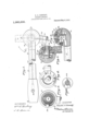
- Figure 1 is a fragmentary detail view in front elevation of the steering-post and steering-arm, the latter occupying" its lowest position, as when the vehicle is in motion.
- Figure 2 is a fragmentary detail horizontal sectional view, on the line 2---2 in Fig. 1.
- Fig. 3 is a fragmentary detail central vertical sectional view on the line 3-3 in Fig. 1.
- Fig. 4 is a plan view of the inner face of the semi-spherical enlargement on the end of the steering-arm and forms a part of the knuckle or joint.
- Fig. 1 is a fragmentary detail view in front elevation of the steering-post and steering-arm, the latter occupying" its lowest position, as when the vehicle is in motion.
- Fig. 2 is a fragmentary detail horizontal sectional view, on the line 2---2 in Fig. 1.
- Fig. 3 is a fragmentary detail central vertical sectional view on the line 3-3 in Fig. 1.
- Fig. 4 is a plan view of the
- FIG. 5 is a plan view of the inner face of the semispherical enlargement. on the end of the steering-postand forms the remaining portion, of the knuckle or joint.
- Fig. (3 is a cross section of the spindle, showing the washer and retaining pin, the remaining construction of the steering device being omitted.
- the vertically disposed steering-post or statf common to electrically driven motor vehicles, comprises a hollow tube 10, having secured to its upper end a semi-spherically shaped member 12 that forms, approximately, one-half of the'bearing or joint between said post and steering-arm.
- the arm comprises a hollow tube H which is provided on one end with a grip or handle 15 and the opposite end of the arm is provided with a semi-spherically shaped member 16, similar to the member 12, the two members 12 and 16 forming the bearing between the steeringspost and steer- 1nr-arm.
- the member 16 is provided on its tlat surface with a centrally lo cated threaded spindle 90 of sutiicient length to project through the member 12 when the two occupy an assen'ibled posit-ion.
- the face of the member 16 is cut away around the base of the spindle 20 to form an annular recess 22, and the member 12 is provided with a similar recess 23.
- the two recesses providing a passageway for conducting the wires 25 around the spindle 20.
- the chamber formed by the recesses 22 and 2 communicates with the hollow interior of the steering post 10 and the steeriireyarm 11- so that an unobstructed conduit or passageway is provided for the wires 25 running from the switch 26, located within the grip to on the steering-anti 14-, to the motor. not shown.
- the semi-s herically shaped mem bers 12 and 16 are in'an assembled condition.
- the former is susceptible of independent rotary movement with respect to the latter, thereby enabling the stecring-arm 14- to be elevated into a vertical position, as shown by means of the dotted lines in Fig. 1.
- the arm will not interfere with the nmvements of the operator in getting into or out of the vehicle.
- This independent n'ioven'ient of the arm and member 16 is limited generally to about no degrees, the distance of travel being controlled by providing an annular groove 28 cut into the fiat face of the member 12 and a correspondingly shaped rib 27 on the tint face of the member 16 which rib rides in said groove.
- a stop-block 36 is set into the in t face of the member 12 and arranged to extend across the groove 28 and acts as a barrier for limiting the travel of the men'iber it? when either of the shoulders 34 and 35111- gage said stop-block.
- the length of rotary travel of the arm depends on the position of the shoulders 34 and 3S and the positions the'surface of the member 12 leaving its "maintain a uniform workingrelationship of these aredeterinined by the amount of metal removed from the rib 27.
- the member 16 is provided with the threaded spindle 20 which projects through air-aperture 29 in the member 12.
- the aperture 29 is enlarged to increaseits diameter to make room for the vvt her id, lock-nut 41 and outer nut 42-whioli screvvdown onthe threaded end of the spindle 20 and whereby the members 12 and 16 are drawn and held together.
- the above arrangement removes the nuts from outer surface smooth and free from obstructions.
- lhe increased diameter of the-aperture 29 also rovides the necessary shoulder 38 upon which the Washer rides when the member 16 is rotated.
- the faceof the shoulder 38 against Which the Washer 4-0 acts is cone-'shaped, as shown, and the ltace of the Washer is formed to correspond thereto.
- the aperture 29 is entirely closed, leaving the exterior surface of the member 12 smooth and thus adding to the general appearance of the device, by inserting the outer-nut 422, the exposed surface of Which is cut on a cnrve'to conform to the curve on which the adjacent surfaces ofthe members 12 and 16 are out, thereby leaving the outline of the sphere molten.
- the 'nuts 1-1 and 42 see and are provided with the aperted at opposite points, adapted moo
- Washer adapted to form a bearing for the free end of the spindle, means to prevent independent rotary movement of said Washer on said spindle, and means for holding the Washer, post and arm in operative relation.
Landscapes
- Engineering & Computer Science (AREA)
- General Engineering & Computer Science (AREA)
- Mechanical Engineering (AREA)
- Steering Controls (AREA)
Description
H. H. KENNEDY STEERING KNUCKLE. APPLICATION FILED APR. 24, 1911.
Patented May 6, 1913.
WI TNESJEaS N yM/ZWW,
OUMTED earns rarnn'r enrich.
HAROLD H. KENNEDY, OF INDIANAPOLIS, INDIANA, ASSIGNOR TO THE WAVERLY COMPANY, A CORPORATION OF INDIANA.
STEERING-KNUCKLE Specification of Letters Patent.
Patented May ti, 1 913.
Application filed Apri124. 1911. Serial No. 623,131.
To (ZZZ about it may concern Be it known that I, I'IAROLD H. Knxlvnnv. a citizen of the United States, residing at Indianapolis, in the county of Marion and State of Indiana. have invented certain new and useful Improvements in Steering-Knuckles, of which the following is a specification.
This invention relates to a joint or knuckle-for steering-posts in electrically driven motor vehicles; and the object of the invention is to provide a steering-post of the above character with a knuckle or joint which is simple in c mstructien, compact. neat. in appearance. strong and durable.
A further object of the invention is to provide a knuckle or joint of the above character wherein aconduit is formed to receive and conceal the electric wires running from the motor to the switch, thus removing all wires from the exterior of the steering-post and also enabling the switch to be placed in an extremely convenient and readily accessible position within the grip or handle of the steering-arm.
I accomplish the objects of the invention by means of the knuckle or joint illustrated in the accompanying drawings, forming a part hereof, in which Figure 1 is a fragmentary detail view in front elevation of the steering-post and steering-arm, the latter occupying" its lowest position, as when the vehicle is in motion. Fig. 2 is a fragmentary detail horizontal sectional view, on the line 2---2 in Fig. 1. Fig. 3 is a fragmentary detail central vertical sectional view on the line 3-3 in Fig. 1. Fig. 4 is a plan view of the inner face of the semi-spherical enlargement on the end of the steering-arm and forms a part of the knuckle or joint. Fig. 5 is a plan view of the inner face of the semispherical enlargement. on the end of the steering-postand forms the remaining portion, of the knuckle or joint. Fig. (3 is a cross section of the spindle, showing the washer and retaining pin, the remaining construction of the steering device being omitted.
Referring to the drawings, the vertically disposed steering-post or statf, common to electrically driven motor vehicles, comprises a hollow tube 10, having secured to its upper end a semi-spherically shaped member 12 that forms, approximately, one-half of the'bearing or joint between said post and steering-arm. The arm comprises a hollow tube H which is provided on one end with a grip or handle 15 and the opposite end of the arm is provided with a semi-spherically shaped member 16, similar to the member 12, the two members 12 and 16 forming the bearing between the steeringspost and steer- 1nr-arm. To securely hold the semispherirally shaped members 12 and 16 together in operative position'the member 16 is provided on its tlat surface with a centrally lo cated threaded spindle 90 of sutiicient length to project through the member 12 when the two occupy an assen'ibled posit-ion.
The face of the member 16 is cut away around the base of the spindle 20 to form an annular recess 22, and the member 12 is provided with a similar recess 23. the two recesses providing a passageway for conducting the wires 25 around the spindle 20. The chamber formed by the recesses 22 and 2 communicates with the hollow interior of the steering post 10 and the steeriireyarm 11- so that an unobstructed conduit or passageway is provided for the wires 25 running from the switch 26, located within the grip to on the steering-anti 14-, to the motor. not shown.
lVhcn the semi-s herically shaped mem bers 12 and 16 are in'an assembled condition. the former is susceptible of independent rotary movement with respect to the latter, thereby enabling the stecring-arm 14- to be elevated into a vertical position, as shown by means of the dotted lines in Fig. 1. In this p sition the arm will not interfere with the nmvements of the operator in getting into or out of the vehicle. This independent n'ioven'ient of the arm and member 16 is limited generally to about no degrees, the distance of travel being controlled by providing an annular groove 28 cut into the fiat face of the member 12 and a correspondingly shaped rib 27 on the tint face of the member 16 which rib rides in said groove. A portion of the rib 27 cut away. as shown at 32, to provide the two shoulders 34- and 3 5. A stop-block 36 is set into the in t face of the member 12 and arranged to extend across the groove 28 and acts as a barrier for limiting the travel of the men'iber it? when either of the shoulders 34 and 35111- gage said stop-block. The length of rotary travel of the arm depends on the position of the shoulders 34 and 3S and the positions the'surface of the member 12 leaving its "maintain a uniform workingrelationship of these aredeterinined by the amount of metal removed from the rib 27.
As hereinbefore stated, the member 16 is provided with the threaded spindle 20 which projects through air-aperture 29 in the member 12. The aperture 29 is enlarged to increaseits diameter to make room for the vvt her id, lock-nut 41 and outer nut 42-whioli screvvdown onthe threaded end of the spindle 20 and whereby the members 12 and 16 are drawn and held together. The above arrangement removes the nuts from outer surface smooth and free from obstructions. lhe increased diameter of the-aperture 29 also rovides the necessary shoulder 38 upon which the Washer rides when the member 16 is rotated. The faceof the shoulder 38 against Which the Washer 4-0 acts is cone-'shaped, as shown, and the ltace of the Washer is formed to correspond thereto. The tendency of these cone-shaped surfaces When brought together isto hold the mem 12 and 16 into alineirlent. The Washer dOis held stationary, so that therotary travel of the member 16 will not loosen. the lock nut 11., by means of horizontally disposed pin 14 which is inserted a recess/ in the spindle 20 before thewaslier 40 is placed into position. The loclonut e1. serves to between the parts When the latter have once been adjusted. This construction further enables the parts to be readjusted to overcome, wear and permits the tension on the parts to he changed to suit conditions. After the lock-nut has been placed into position the aperture 29 is entirely closed, leaving the exterior surface of the member 12 smooth and thus adding to the general appearance of the device, by inserting the outer-nut 422, the exposed surface of Which is cut on a cnrve'to conform to the curve on which the adjacent surfaces ofthe members 12 and 16 are out, thereby leaving the outline of the sphere molten. The 'nuts 1-1 and 42 (see and are provided with the aperted at opposite points, adapted moo,
to receive a suitable spanner-wrench by which said nuts are forced into position.
Having thus fully described my said invention, what I desire to secure by Letters Patent, is
1..Tho combination, with a steering-post, a steering arm, an enlargement tormed on one end of the post and arm, an annular groove formed in one of the enlargements, a segmental rib formed on the other enlargement, said rib adapted to engage said groove, means to limit the rotary travel between said enlargements, and means for holding said post and arm in operative relation.
2. The combination, -Wltl1 a steering-post, an enlargement thereon, an annular groove formed in the face of said enlargement, a steering-arm, an enlargement formed there on, a rib formedon the face of said enlargement and adapted to ride in said groove, means extending across said groove to limit the rotary travel of said arm, and means for holding the post and arm in operative relation.
3. The combination, with a steering-post, an enlargement formed on said post and provided with a transverse aperture, an annular groove formed in the face of said enlargement, a steering-arm, an enlargement formed thereon, a rib formed on the face of said enlargement and adapted to ride in said groove, a spindle on the enlargement on said arm adapted to extend through the aperture in the enlargementon'the post, a
Washer adapted to form a bearing for the free end of the spindle, means to prevent independent rotary movement of said Washer on said spindle, and means for holding the Washer, post and arm in operative relation. In witness whereof, I have hereunto set my hand and seal at Indianapolis, Indiana, this, 18th day of April, A. D. one thousand nine hundred and eleven.
nnnoiin n. KENNEDY; [1,. 5. 'Witnesses JOSEPH A. Mnvrunn, F. W. Wonannn.
Priority Applications (1)
| Application Number | Priority Date | Filing Date | Title |
|---|---|---|---|
| US62313111A US1060606A (en) | 1911-04-24 | 1911-04-24 | Steering-knuckle. |
Applications Claiming Priority (1)
| Application Number | Priority Date | Filing Date | Title |
|---|---|---|---|
| US62313111A US1060606A (en) | 1911-04-24 | 1911-04-24 | Steering-knuckle. |
Publications (1)
| Publication Number | Publication Date |
|---|---|
| US1060606A true US1060606A (en) | 1913-05-06 |
Family
ID=3128854
Family Applications (1)
| Application Number | Title | Priority Date | Filing Date |
|---|---|---|---|
| US62313111A Expired - Lifetime US1060606A (en) | 1911-04-24 | 1911-04-24 | Steering-knuckle. |
Country Status (1)
| Country | Link |
|---|---|
| US (1) | US1060606A (en) |
-
1911
- 1911-04-24 US US62313111A patent/US1060606A/en not_active Expired - Lifetime
Similar Documents
| Publication | Publication Date | Title |
|---|---|---|
| US2281097A (en) | Joint construction | |
| US1384309A (en) | Motor-vehicle | |
| US1693840A (en) | Ball and socket joint | |
| US845513A (en) | Adjustable shaft-support. | |
| US1994582A (en) | Steering gear connection for automotive vehicles | |
| US904137A (en) | Steering mechanism for automobiles. | |
| US1000893A (en) | Steering-gear connection. | |
| US1171224A (en) | Steering-wheel of motor-vehicles. | |
| US1141290A (en) | Vehicle steering mechanism. | |
| US983991A (en) | Automobile headlight-adjuster. | |
| US1095873A (en) | Handle attachment. | |
| US1337138A (en) | Steering reach-lod | |
| US1269341A (en) | Shiftable steering-wheel. | |
| US722723A (en) | Steering-gear for motor-vehicles. | |
| US248055A (en) | James old | |
| US974034A (en) | Vehicle-lantern. | |
| US1675915A (en) | Dirigibly-mounted light | |
| US1028144A (en) | Lamp attachment for vehicles. | |
| USRE14579E (en) | Ments | |
| US886508A (en) | Steering device for automobiles. | |
| US1121824A (en) | Dirigible head-lamp for vehicles. | |
| US982117A (en) | Combination power and steering knuckle. | |
| US865318A (en) | Valve. | |
| US809171A (en) | Steering device. | |
| US1659082A (en) | Vehicle hand signal |