US10604258B2 - Cart stowage placard enabling plate - Google Patents
Cart stowage placard enabling plate Download PDFInfo
- Publication number
- US10604258B2 US10604258B2 US15/233,606 US201615233606A US10604258B2 US 10604258 B2 US10604258 B2 US 10604258B2 US 201615233606 A US201615233606 A US 201615233606A US 10604258 B2 US10604258 B2 US 10604258B2
- Authority
- US
- United States
- Prior art keywords
- cart
- plate
- placard
- edge
- rotating
- Prior art date
- Legal status (The legal status is an assumption and is not a legal conclusion. Google has not performed a legal analysis and makes no representation as to the accuracy of the status listed.)
- Active, expires
Links
Images


Classifications
-
- B—PERFORMING OPERATIONS; TRANSPORTING
- B64—AIRCRAFT; AVIATION; COSMONAUTICS
- B64D—EQUIPMENT FOR FITTING IN OR TO AIRCRAFT; FLIGHT SUITS; PARACHUTES; ARRANGEMENTS OR MOUNTING OF POWER PLANTS OR PROPULSION TRANSMISSIONS IN AIRCRAFT
- B64D11/00—Passenger or crew accommodation; Flight-deck installations not otherwise provided for
- B64D11/04—Galleys
-
- B—PERFORMING OPERATIONS; TRANSPORTING
- B64—AIRCRAFT; AVIATION; COSMONAUTICS
- B64D—EQUIPMENT FOR FITTING IN OR TO AIRCRAFT; FLIGHT SUITS; PARACHUTES; ARRANGEMENTS OR MOUNTING OF POWER PLANTS OR PROPULSION TRANSMISSIONS IN AIRCRAFT
- B64D11/00—Passenger or crew accommodation; Flight-deck installations not otherwise provided for
- B64D11/0007—Devices specially adapted for food or beverage distribution services
Definitions
- Embodiments of the disclosure relate generally to storage of galley carts and more particularly to a rotatable placard plate retractably positioned to indicate a missing half size cart in an interior galley storage location.
- the embodiments provide a method for displaying and retracting a placard in a galley cart storage bay by suspending an outer rotatable plate carrying a placard in a first position from an upper surface over a central storage position. The outer rotatable plate is then rotated in a first direction responsive to contact by a first edge of a galley cart allowing insertion of the cart under the rotated plate.
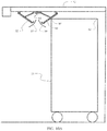
- FIG. 1A is an exemplary galley layout providing storage bays for 7 galley cart widths
- FIG. 1B is an exemplary galley layout providing storage bays for 5 galley cart widths
- FIG. 2A is a representation of a full size galley cart
- FIG. 3 is a representation of a storage configuration of combined full size and half size carts in a three cart width galley bay;
- FIG. 4A is a representation of the three cart width bay in a first fully loaded configuration
- FIG. 4B is a representation of the three cart width bay of FIG. 4A in a partially loaded configuration
- FIG. 5B is a representation of the three cart width bay of FIG. 5A in a fully loaded configuration
- FIG. 6A is a representation of the three cart width bay in a third partially loaded configuration
- FIG. 6B is a representation of the three cart width bay in a fourth partially loaded configuration
- FIG. 7 is a side view of an exemplary embodiment of the rotatable placard plate assembly
- FIG. 8 is a pictorial representation of the exemplary embodiment
- FIG. 10A is a side view of the exemplary embodiment demonstrating commencement of retraction during the initial stage of withdrawal of a half size cart from a rear position;
- FIG. 10B is a side view of the exemplary embodiment during the fully retracted stage during of withdrawal of the half size cart;
- FIG. 12A is a top view of the actuation mechanism of the rotatable placard plate assembly in the unrotated position corresponding to FIG. 8 ;
- FIG. 12B is a top view of the actuation mechanism of the rotatable placard plate assembly in the partially rotated position corresponding to FIG. 9 ;
- FIG. 12C is a top view of the actuation mechanism of the rotatable placard plate assembly in the fully rotated position corresponding to FIG. 10 or 11 ;
- FIG. 13 is a flow chart demonstrating a method for employing the embodiments disclosed herein.
- the embodiments herein provide a means for placarding galley cart bays which is identifiable for all partial loading conditions of the bay. More specifically, the embodiments described herein provide a placard system for a central cart positions in a galley bay which is retractable to allow insertion or removal of either fully size or half size carts but remains in an extended position if no cart or a single half cart is inserted in the position.
- a rotatable plate supports a placard indicative of the galley capacity, number or weight of galley cart storage within an aircraft galley compartment and provides visibility to the cabin flight crew until final cart placement within the compartment.
- the placard In function the placard is mechanically placed in a position visible to the cabin flight crew such that when a galley cart storage bay position which is not adjacent a wall of the bay is empty or contains a half size cart the placard remains visible. At the insertion of the final capacity galley cart the placard mechanical retracts from obstructing the cart placement within the storage area and from view of the cabin flight crew.
- FIG. 1A shows an exemplary configuration for a galley 10 having a work counter 12 , wall bins 14 , coffee makers 16 and three storage bays 18 a , 18 b and 18 c for galley carts 20 .
- Storage bays 18 a and 18 c are configured with a two cart width while storage bay 18 b is configured with a three cart width allowing storage of seven full size carts or up to 14 half size carts with any mixture of full and half size carts desired.
- FIG. 1B shows a second exemplary configuration for a galley 11 with two storage bays 19 a and 19 b of two and three cart widths respectively for storage of 5 full size carts 20 or up to 10 half size carts 21 .
- Alternative embodiments with bays of up to four cart widths may be employed and galleys employing only a single bay of three or four cart widths are also common.
- FIG. 2A is a representation of a full size cart 20 having a height 22 , width 24 and depth 26 .
- FIG. 2B is a representation of a half size cart 21 showing a common height 22 and width 24 with the full size cart but a half depth 28 (wheels of the carts have not been shown for simplicity).
- FIG. 3 shows an exemplary three cart width bay 30 in which a full size cart 20 is stored in a left storage position 32 adjacent a left wall 34 , two half size carts 21 a and 21 b are stored in central storage position 36 and two half size carts 21 c and 21 d are stored in a right storage position 38 adjacent a right wall 40 of the bay 30 .
- FIG. 4A shows the bay 30 fully loaded with half size carts 21 a and 21 b in the left storage position 32 , a full size cart 20 in the central storage position 36 and two half size carts 21 c and 21 d in the right storage position 38 .
- the full size cart 20 removed from the central storage position 36 and the outer half size carts 21 a and 21 c removed from the left and right storage positions 32 , 38 , respectively, as seen in FIG. 4B for a first partially filled condition of the bay, placards 42 placed on the left wall 34 , right wall 40 , and rear wall 44 are visible indicating that carts are missing from the bay.
- FIG. 4B shows the bay 30 fully loaded with half size carts 21 a and 21 b in the left storage position 32 , a full size cart 20 in the central storage position 36 and two half size carts 21 c and 21 d in the right storage position 38 .
- the central storage location is filled with a full size cart 20 obscuring the placard on the rear wall 44 .
- the right and left storage positions each contain a half size cart 21 b and 21 d .
- the placards on the left wall 34 and right wall 40 are visible so this is an acceptable condition.
- FIG. 6B for a fourth partially filled configuration loading of a full size cart 20 in the left storage position and two half size carts 21 c and 21 d in the right storage position obscures the placards on the left and right walls 34 and 40 respectively, which is acceptable since those positions are filled.
- FIG. 7 An exemplary embodiment of the retractable placard system which remedies this condition is shown in FIG. 7 .
- the bay 30 under work counter 12 is shown with one half size cart 21 for reference.
- the retractable placard system 50 employs an outer plate 52 which is attached to an upper surface 54 of the bay 30 , which for the embodiment shown is a lower surface of the work counter 12 in the galley. With the central storage position 36 in the bay 30 empty or with one half size cart loaded, the outer plate 52 depends substantially vertically downward in the central storage position and a placard 55 is displayed on the outer plate as seen in FIG. 8 .
- the outer plate 52 is mounted to the surface 54 with a hinge 56 allowing the outer plate to rotate in a first direction represented by arrow 57 in FIG.
- an inner plate 60 is mounted to the surface 54 in the bay 30 with a hinge 62 as a cart removal sensor.
- the outer plate 52 and inner plate 60 are connected with a linkage 64 .
- a first compression/tension arm 66 attached to the outer plate 52 extends to a first end 68 of a rotating arm 70 .
- the rotating arm 70 is mounted to the surface 54 with a pivot 72 .
- a second compression/tension arm 74 attached to the inner plate 60 extends to a second end 76 of the rotating arm 70 . Connection of the compression/tension arms 66 and 74 to the outer and inner plates 52 and 60 and the rotating arm 70 is accomplished with universal joints 78 .
- the cart removal sensor may employ electrical or optical sensing of position of a cart and the linkage may comprise an electromechanical rotation mechanism responsive to the sensor for rotating the outer plate 52 .
- the cart removal sensor is any suitable sensor that detects proximity of the half size cart being removed from the cart storage bay.
- the cart 21 may be pushed to the rear of the central storage position 36 and as an outer upper edge 88 of the cart 21 clears the foot 84 of the inner plate 60 , both the inner plate 60 and outer plate 52 will rotate downwardly to the initial position shown in FIG. 7 .
- Weight of the inner and outer plates 60 , 52 may be employed to cause the downward rotation by gravity. However, spring assists in the linkage to urge the plates positively in a downward direction may be used.
- the outer upper edge 88 of the cart 21 contacts the inner plate 60 as the removal sensor detecting the proximity of the cart 21 for removal and causes the inner plate 60 to rotate in the second direction 80 .
- the linkage 64 causes a complimentary rotation by the outer plate 52 in the first direction 57 .
- FIG. 10B when the inner plate 60 has rotated sufficiently for the cart 21 to pass under the inner plate 60 , the outer plate 52 has been rotated sufficiently for the cart 21 to pass.
- both the inner plate 60 and outer plate 52 will rotate downwardly to the initial position shown in FIG. 7 .
- a second cart 21 b may be installed with a process rotating the outer and inner plates 52 , 60 similar to that described with respect to FIGS. A and 9 B. As shown in FIG. 11 the rotated outer plate 52 and inner plate 60 will be maintained in the rotated position by the presence of the second cart 21 b thereby maintaining the retracted position of the placard 55 attached to the outer plate 52 .
- FIGS. 12A-12C Operation of the linkage 64 to obtain complimentary rotation of the outer plate 52 and inner plate 60 is seen in FIGS. 12A-12C .
- the compression/tension arm 66 is attached with universal joint 78 to an edge 90 of the outer plate 52 , substantially perpendicular to the hinge 56 (as seen in FIG. 7 ), at approximately a midpoint 92 as best seen in FIGS. 12B and 12C .
- Compression/tension arm 74 is attached to an edge 94 of the inner plate 60 with a universal joint 78 at approximately a midpoint 96 .
- the extended or unrotated position of the inner and outer plates 52 , 60 is shown in FIG. 12A corresponding to the position shown in FIGS. 7 and 8 .
- FIGS. 9A and 10A Upon contact by a cart 20 or 21 with either the outer plate 52 or inner plate 60 , rotation of the plate 52 or 60 causes compression of the respective arm 66 or 74 which is transmitted to the rotating arm 70 causing rotation about the pivot 72 .
- the rotating arm 70 then causes tension in the opposite arm 74 or 66 inducing complimentary rotation of the inner plate 60 or outer plate 52 .
- the partially rotated position corresponding to FIGS. 9A and 10A is shown in FIG. 12B while the fully rotated position of FIGS. 9B, 10B and 11 is shown in FIG. 12C .
- the embodiment disclosed herein may be constructed to provide a retractable placard system 50 by rotatably suspending an outer plate 52 from a surface 54 of a cart storage bay, step 1302 .
- the rotation of the outer plate 52 compresses a first compression/tension arm 66 connected to an edge 90 of the outer plate 52 , step 1308 .
- a rotating arm 70 connected at a first end 68 to the first compression/tension arm 66 and mounted to a pivot 72 on the surface 54 of the bay 30 is rotated, step 1310 , placing tension on a second compression/tension arm 74 connected to a second end 76 of the rotating arm 70 and further connected to an edge 94 of the inner plate 60 to rotate the inner plate 60 in a second direction 80 , step 1312 .
- the cart 21 is then moved to a rear location in the central storage position 36 , step 1314 , and the outer plate 52 is rotated back to the first position for viewing of the placard 55 , step 1316 .
- the half size cart 21 is moved from the rear location and proximity of the galley cart 21 is sensed with a sensor, step 1318 , which for the embodiments disclosed is accomplished by contacting a second edge 88 of the cart 21 with the inner plate 60 to rotate in the second direction 80 .
- the outer plate 52 is then rotated in the first direction 57 with a linkage 64 responsive to the sensor, which for the embodiment disclosed is accomplished by compressing the second compression/tension arm 74 , step 1320 .
- the rotating arm 70 is rotated, step, 1322 and tension is exerted on the first compression/tension arm 66 to rotate the outer plate 52 in the first direction 57 , step 1324 , allowing removal of the galley cart 21 under the rotated plates 52 , 60 .
- Step 1326 When a second half size cart 21 b is inserted into the central storage position 36 , the outer plate 52 is rotated in the first direction 57 responsive to contact by a first edge 82 of the second galley cart 21 b allowing insertion of the second galley cart 21 b under the rotated outer plate 52 , step 1326 .
- Steps 1308 to 1312 are accomplished in the exemplary embodiments to also rotate the inner plate 60 for clearance of the second galley cart 21 b .
- the inner plate 60 is maintained in a second position with the placard 55 retracted from view, step 1328 , with both carts 21 a , 21 b inserted in the central storage position 36 .
Abstract
Description
Claims (20)
Priority Applications (5)
| Application Number | Priority Date | Filing Date | Title |
|---|---|---|---|
| US15/233,606 US10604258B2 (en) | 2016-08-10 | 2016-08-10 | Cart stowage placard enabling plate |
| CA2966103A CA2966103C (en) | 2016-08-10 | 2017-05-02 | Cart stowage placard enabling plate |
| BR102017011408-2A BR102017011408B1 (en) | 2016-08-10 | 2017-05-30 | RETRACTABLE SCOREBOARD SYSTEM FOR GALLE CART STORAGE BAYS, AIRCRAFT GALLET, AND METHOD FOR DISPLAYING AND RETRACTING A SCOREBOARD IN A GALLE CART STORAGE BOX |
| JP2017147774A JP6416999B2 (en) | 2016-08-10 | 2017-07-31 | Plates that allow cart storage place placards |
| JP2018189227A JP6684879B2 (en) | 2016-08-10 | 2018-10-04 | A plate that enables a cart storage placard |
Applications Claiming Priority (1)
| Application Number | Priority Date | Filing Date | Title |
|---|---|---|---|
| US15/233,606 US10604258B2 (en) | 2016-08-10 | 2016-08-10 | Cart stowage placard enabling plate |
Publications (2)
| Publication Number | Publication Date |
|---|---|
| US20180044021A1 US20180044021A1 (en) | 2018-02-15 |
| US10604258B2 true US10604258B2 (en) | 2020-03-31 |
Family
ID=61160760
Family Applications (1)
| Application Number | Title | Priority Date | Filing Date |
|---|---|---|---|
| US15/233,606 Active 2038-02-22 US10604258B2 (en) | 2016-08-10 | 2016-08-10 | Cart stowage placard enabling plate |
Country Status (4)
| Country | Link |
|---|---|
| US (1) | US10604258B2 (en) |
| JP (2) | JP6416999B2 (en) |
| BR (1) | BR102017011408B1 (en) |
| CA (1) | CA2966103C (en) |
Cited By (4)
| Publication number | Priority date | Publication date | Assignee | Title |
|---|---|---|---|---|
| US20190031348A1 (en) * | 2017-07-31 | 2019-01-31 | Airbus Operations Gmbh | Stowage And Removal System For Rollable Containers In A Vehicle, And A Vehicle, In Particular A Commercial Aircraft, With Such A System |
| US10906173B2 (en) * | 2018-11-15 | 2021-02-02 | Zezhi Intellectual Property Service | Smart cabinet |
| US20210093086A1 (en) * | 2018-11-15 | 2021-04-01 | Zezhi Intellectual Property Service | Smart cabinet |
| US20220234741A1 (en) * | 2021-01-27 | 2022-07-28 | B/E Aerospace, Inc. | Galley equipment hazards alert |
Citations (9)
| Publication number | Priority date | Publication date | Assignee | Title |
|---|---|---|---|---|
| US20050081418A1 (en) * | 2003-10-15 | 2005-04-21 | Jacob Fast | Hinged label holder |
| US20050224646A1 (en) | 2004-03-26 | 2005-10-13 | The Boeing Company | Overhead space access conversion monument and service area staircase and stowage system |
| DE102007029677A1 (en) | 2007-06-27 | 2009-01-22 | Edag Gmbh & Co. Kgaa | Compartment system for catering device of e.g. aircraft, has handle bars arranged at compartment front side, movable between release position and safety position and aligned in longitudinal direction in release position or safety position |
| US20110090064A1 (en) * | 2009-10-21 | 2011-04-21 | Airbus Operations Gmbh | System and method for stockkeeping in an aircraft galley |
| US20130269545A1 (en) * | 2009-06-05 | 2013-10-17 | B/E Aerospace, Inc. | Space-Saving In-Flight Trash Compactor |
| US20150069179A1 (en) | 2013-09-11 | 2015-03-12 | Airbus Operations Gmbh | Expandable galley |
| JP2015051741A (en) | 2013-09-09 | 2015-03-19 | 株式会社ジャムコ | Galley safety monitoring system |
| US20150314872A1 (en) | 2014-04-30 | 2015-11-05 | Airbus Operations Gmbh | Galley Segment For A Cabin Of A Vehicle, Cabin Of A Vehicle And Aircraft Having A Cabin With Such A Galley Segment |
| WO2016034531A1 (en) | 2014-09-05 | 2016-03-10 | Sell Gmbh | Trolley arrangement of a galley of a vehicle, especially of an aircraft |
-
2016
- 2016-08-10 US US15/233,606 patent/US10604258B2/en active Active
-
2017
- 2017-05-02 CA CA2966103A patent/CA2966103C/en active Active
- 2017-05-30 BR BR102017011408-2A patent/BR102017011408B1/en active IP Right Grant
- 2017-07-31 JP JP2017147774A patent/JP6416999B2/en active Active
-
2018
- 2018-10-04 JP JP2018189227A patent/JP6684879B2/en active Active
Patent Citations (9)
| Publication number | Priority date | Publication date | Assignee | Title |
|---|---|---|---|---|
| US20050081418A1 (en) * | 2003-10-15 | 2005-04-21 | Jacob Fast | Hinged label holder |
| US20050224646A1 (en) | 2004-03-26 | 2005-10-13 | The Boeing Company | Overhead space access conversion monument and service area staircase and stowage system |
| DE102007029677A1 (en) | 2007-06-27 | 2009-01-22 | Edag Gmbh & Co. Kgaa | Compartment system for catering device of e.g. aircraft, has handle bars arranged at compartment front side, movable between release position and safety position and aligned in longitudinal direction in release position or safety position |
| US20130269545A1 (en) * | 2009-06-05 | 2013-10-17 | B/E Aerospace, Inc. | Space-Saving In-Flight Trash Compactor |
| US20110090064A1 (en) * | 2009-10-21 | 2011-04-21 | Airbus Operations Gmbh | System and method for stockkeeping in an aircraft galley |
| JP2015051741A (en) | 2013-09-09 | 2015-03-19 | 株式会社ジャムコ | Galley safety monitoring system |
| US20150069179A1 (en) | 2013-09-11 | 2015-03-12 | Airbus Operations Gmbh | Expandable galley |
| US20150314872A1 (en) | 2014-04-30 | 2015-11-05 | Airbus Operations Gmbh | Galley Segment For A Cabin Of A Vehicle, Cabin Of A Vehicle And Aircraft Having A Cabin With Such A Galley Segment |
| WO2016034531A1 (en) | 2014-09-05 | 2016-03-10 | Sell Gmbh | Trolley arrangement of a galley of a vehicle, especially of an aircraft |
Cited By (7)
| Publication number | Priority date | Publication date | Assignee | Title |
|---|---|---|---|---|
| US20190031348A1 (en) * | 2017-07-31 | 2019-01-31 | Airbus Operations Gmbh | Stowage And Removal System For Rollable Containers In A Vehicle, And A Vehicle, In Particular A Commercial Aircraft, With Such A System |
| US11390383B2 (en) * | 2017-07-31 | 2022-07-19 | Airbus Operations Gmbh | Stowage and removal system for rollable containers in a vehicle, and a vehicle, in particular a commercial aircraft, with such a system |
| US10906173B2 (en) * | 2018-11-15 | 2021-02-02 | Zezhi Intellectual Property Service | Smart cabinet |
| US20210093086A1 (en) * | 2018-11-15 | 2021-04-01 | Zezhi Intellectual Property Service | Smart cabinet |
| US11638481B2 (en) * | 2018-11-15 | 2023-05-02 | Zezhi Intellectual Property Service | Smart cabinet |
| US20220234741A1 (en) * | 2021-01-27 | 2022-07-28 | B/E Aerospace, Inc. | Galley equipment hazards alert |
| US11919644B2 (en) * | 2021-01-27 | 2024-03-05 | B/E Aerospace, Inc. | Galley equipment hazards alert |
Also Published As
| Publication number | Publication date |
|---|---|
| BR102017011408A2 (en) | 2018-02-27 |
| JP2019069760A (en) | 2019-05-09 |
| JP6416999B2 (en) | 2018-10-31 |
| JP6684879B2 (en) | 2020-04-22 |
| CA2966103A1 (en) | 2018-02-10 |
| CA2966103C (en) | 2021-05-18 |
| BR102017011408A8 (en) | 2022-07-26 |
| US20180044021A1 (en) | 2018-02-15 |
| BR102017011408B1 (en) | 2022-09-06 |
| JP2018070140A (en) | 2018-05-10 |
Similar Documents
| Publication | Publication Date | Title |
|---|---|---|
| US10604258B2 (en) | Cart stowage placard enabling plate | |
| US9610879B2 (en) | Seatback for a passenger seat | |
| EP2673549B1 (en) | Tablet holder and tablet stowage system | |
| EP2569187B1 (en) | Coupling assembly | |
| US11305876B2 (en) | Aircraft cabin apparatus including personal electronic device holder | |
| WO2013045624A1 (en) | Cover for a seat in an aircraft or spacecraft | |
| KR101716597B1 (en) | Method for protecting a passenger and device consisting of a folding table and a seat screen | |
| CN113303593B (en) | Hidden computer mounting structure | |
| CN108001690A (en) | Rotate recoverable pedal system | |
| CA2958469A1 (en) | Interface for aircraft and control process for such an interface | |
| FR2935184A1 (en) | Integrated cargo loading/unloading and video-controlling system for airplane, has display screen communicated with processor, where screen selectively displays information received from driving blocks | |
| CN104660996B (en) | Display device and control method are shot with video-corder in a kind of aircraft landing | |
| CN107826232A (en) | Aircraft cabin regions include the aircraft and its operating method of the aircraft cabin regions | |
| FR2941916A1 (en) | MODULAR CABINET FOR AN AIRCRAFT | |
| WO2020197567A1 (en) | Imbedded sensors for passenger seats | |
| CN208622177U (en) | A kind of Vending Machine and its cargo bearing device | |
| US7251126B2 (en) | Rotatably retractable image display system | |
| US11008103B1 (en) | Aircraft cabin apparatus including personal electronic device holder | |
| US20130241382A1 (en) | Aircraft galley stowage compartment extractor | |
| CN106586160A (en) | Test tube preparing machine | |
| CN103863573B (en) | The automation of luggage and the method for personalisation process and aircraft hold in airborne vehicle | |
| CN217932826U (en) | Goods discharging structure of vending machine | |
| CN214671480U (en) | Dangerous warning device is used in commodity circulation service | |
| CN211862410U (en) | Foldable display stand for retail commodity display | |
| CN219479692U (en) | A show stand for cigarette exhibition |
Legal Events
| Date | Code | Title | Description |
|---|---|---|---|
| AS | Assignment |
Owner name: THE BOEING COMPANY, ILLINOIS Free format text: ASSIGNMENT OF ASSIGNORS INTEREST;ASSIGNORS:SINGLETON, CHRISTOPHER B.;LEE, JOSHUA Y.;GARCIA, EMMANUEL A.;REEL/FRAME:039645/0276 Effective date: 20160809 |
|
| STPP | Information on status: patent application and granting procedure in general |
Free format text: NON FINAL ACTION MAILED |
|
| STPP | Information on status: patent application and granting procedure in general |
Free format text: RESPONSE TO NON-FINAL OFFICE ACTION ENTERED AND FORWARDED TO EXAMINER |
|
| STPP | Information on status: patent application and granting procedure in general |
Free format text: FINAL REJECTION MAILED |
|
| STPP | Information on status: patent application and granting procedure in general |
Free format text: RESPONSE AFTER FINAL ACTION FORWARDED TO EXAMINER |
|
| STPP | Information on status: patent application and granting procedure in general |
Free format text: NOTICE OF ALLOWANCE MAILED -- APPLICATION RECEIVED IN OFFICE OF PUBLICATIONS |
|
| STPP | Information on status: patent application and granting procedure in general |
Free format text: AWAITING TC RESP., ISSUE FEE NOT PAID |
|
| STPP | Information on status: patent application and granting procedure in general |
Free format text: NOTICE OF ALLOWANCE MAILED -- APPLICATION RECEIVED IN OFFICE OF PUBLICATIONS |
|
| STPP | Information on status: patent application and granting procedure in general |
Free format text: PUBLICATIONS -- ISSUE FEE PAYMENT RECEIVED |
|
| STPP | Information on status: patent application and granting procedure in general |
Free format text: PUBLICATIONS -- ISSUE FEE PAYMENT VERIFIED |
|
| STCF | Information on status: patent grant |
Free format text: PATENTED CASE |
|
| MAFP | Maintenance fee payment |
Free format text: PAYMENT OF MAINTENANCE FEE, 4TH YEAR, LARGE ENTITY (ORIGINAL EVENT CODE: M1551); ENTITY STATUS OF PATENT OWNER: LARGE ENTITY Year of fee payment: 4 |