US10602274B2 - Audio input/output device - Google Patents
Audio input/output device Download PDFInfo
- Publication number
- US10602274B2 US10602274B2 US16/233,086 US201816233086A US10602274B2 US 10602274 B2 US10602274 B2 US 10602274B2 US 201816233086 A US201816233086 A US 201816233086A US 10602274 B2 US10602274 B2 US 10602274B2
- Authority
- US
- United States
- Prior art keywords
- audio
- collection unit
- user
- audio collection
- microphone
- Prior art date
- Legal status (The legal status is an assumption and is not a legal conclusion. Google has not performed a legal analysis and makes no representation as to the accuracy of the status listed.)
- Active
Links
- 230000005236 sound signal Effects 0.000 description 3
- 230000008901 benefit Effects 0.000 description 2
- 238000010586 diagram Methods 0.000 description 1
- 238000000034 method Methods 0.000 description 1
Images


Classifications
-
- H—ELECTRICITY
- H04—ELECTRIC COMMUNICATION TECHNIQUE
- H04R—LOUDSPEAKERS, MICROPHONES, GRAMOPHONE PICK-UPS OR LIKE ACOUSTIC ELECTROMECHANICAL TRANSDUCERS; DEAF-AID SETS; PUBLIC ADDRESS SYSTEMS
- H04R5/00—Stereophonic arrangements
- H04R5/033—Headphones for stereophonic communication
- H04R5/0335—Earpiece support, e.g. headbands or neckrests
-
- H—ELECTRICITY
- H04—ELECTRIC COMMUNICATION TECHNIQUE
- H04R—LOUDSPEAKERS, MICROPHONES, GRAMOPHONE PICK-UPS OR LIKE ACOUSTIC ELECTROMECHANICAL TRANSDUCERS; DEAF-AID SETS; PUBLIC ADDRESS SYSTEMS
- H04R1/00—Details of transducers, loudspeakers or microphones
- H04R1/10—Earpieces; Attachments therefor ; Earphones; Monophonic headphones
- H04R1/1091—Details not provided for in groups H04R1/1008 - H04R1/1083
-
- H—ELECTRICITY
- H04—ELECTRIC COMMUNICATION TECHNIQUE
- H04R—LOUDSPEAKERS, MICROPHONES, GRAMOPHONE PICK-UPS OR LIKE ACOUSTIC ELECTROMECHANICAL TRANSDUCERS; DEAF-AID SETS; PUBLIC ADDRESS SYSTEMS
- H04R5/00—Stereophonic arrangements
- H04R5/02—Spatial or constructional arrangements of loudspeakers
-
- H—ELECTRICITY
- H04—ELECTRIC COMMUNICATION TECHNIQUE
- H04R—LOUDSPEAKERS, MICROPHONES, GRAMOPHONE PICK-UPS OR LIKE ACOUSTIC ELECTROMECHANICAL TRANSDUCERS; DEAF-AID SETS; PUBLIC ADDRESS SYSTEMS
- H04R5/00—Stereophonic arrangements
- H04R5/027—Spatial or constructional arrangements of microphones, e.g. in dummy heads
-
- H—ELECTRICITY
- H04—ELECTRIC COMMUNICATION TECHNIQUE
- H04R—LOUDSPEAKERS, MICROPHONES, GRAMOPHONE PICK-UPS OR LIKE ACOUSTIC ELECTROMECHANICAL TRANSDUCERS; DEAF-AID SETS; PUBLIC ADDRESS SYSTEMS
- H04R5/00—Stereophonic arrangements
- H04R5/033—Headphones for stereophonic communication
-
- H—ELECTRICITY
- H04—ELECTRIC COMMUNICATION TECHNIQUE
- H04R—LOUDSPEAKERS, MICROPHONES, GRAMOPHONE PICK-UPS OR LIKE ACOUSTIC ELECTROMECHANICAL TRANSDUCERS; DEAF-AID SETS; PUBLIC ADDRESS SYSTEMS
- H04R5/00—Stereophonic arrangements
- H04R5/04—Circuit arrangements, e.g. for selective connection of amplifier inputs/outputs to loudspeakers, for loudspeaker detection, or for adaptation of settings to personal preferences or hearing impairments
-
- H—ELECTRICITY
- H04—ELECTRIC COMMUNICATION TECHNIQUE
- H04R—LOUDSPEAKERS, MICROPHONES, GRAMOPHONE PICK-UPS OR LIKE ACOUSTIC ELECTROMECHANICAL TRANSDUCERS; DEAF-AID SETS; PUBLIC ADDRESS SYSTEMS
- H04R1/00—Details of transducers, loudspeakers or microphones
- H04R1/10—Earpieces; Attachments therefor ; Earphones; Monophonic headphones
- H04R1/1041—Mechanical or electronic switches, or control elements
-
- H—ELECTRICITY
- H04—ELECTRIC COMMUNICATION TECHNIQUE
- H04R—LOUDSPEAKERS, MICROPHONES, GRAMOPHONE PICK-UPS OR LIKE ACOUSTIC ELECTROMECHANICAL TRANSDUCERS; DEAF-AID SETS; PUBLIC ADDRESS SYSTEMS
- H04R1/00—Details of transducers, loudspeakers or microphones
- H04R1/10—Earpieces; Attachments therefor ; Earphones; Monophonic headphones
- H04R1/1083—Reduction of ambient noise
-
- H—ELECTRICITY
- H04—ELECTRIC COMMUNICATION TECHNIQUE
- H04R—LOUDSPEAKERS, MICROPHONES, GRAMOPHONE PICK-UPS OR LIKE ACOUSTIC ELECTROMECHANICAL TRANSDUCERS; DEAF-AID SETS; PUBLIC ADDRESS SYSTEMS
- H04R1/00—Details of transducers, loudspeakers or microphones
- H04R1/20—Arrangements for obtaining desired frequency or directional characteristics
- H04R1/32—Arrangements for obtaining desired frequency or directional characteristics for obtaining desired directional characteristic only
- H04R1/40—Arrangements for obtaining desired frequency or directional characteristics for obtaining desired directional characteristic only by combining a number of identical transducers
- H04R1/406—Arrangements for obtaining desired frequency or directional characteristics for obtaining desired directional characteristic only by combining a number of identical transducers microphones
-
- H—ELECTRICITY
- H04—ELECTRIC COMMUNICATION TECHNIQUE
- H04R—LOUDSPEAKERS, MICROPHONES, GRAMOPHONE PICK-UPS OR LIKE ACOUSTIC ELECTROMECHANICAL TRANSDUCERS; DEAF-AID SETS; PUBLIC ADDRESS SYSTEMS
- H04R3/00—Circuits for transducers, loudspeakers or microphones
- H04R3/005—Circuits for transducers, loudspeakers or microphones for combining the signals of two or more microphones
Definitions
- the present disclosure generally relates to an audio device. More specifically, the present disclosure relates to a wearable audio device, which can be mounted to a user and is capable of receiving audio inputs and generating audio outputs.
- Wearable audio device having an audio output element such as a speaker
- an audio output element such as a speaker
- a problem to be solved is to make sure that the audio input element can receive audio inputs that are clear.
- a wearable audio input/output device includes a frame that can be mounted to a user, a first audio collection unit provided on the frame, a second audio collection unit provided on the frame, and a first speaker provided on the frame.
- the second audio collection unit is arranged such that the distance between the first audio collection unit and mouth of the user is less than the distance between the second audio collection unit and the mouth of the user when the frame is mounted to the user.
- the first speaker is provided on the frame between the first audio collection unit and the second audio collection unit.
- the positional arrangement of the first audio collection unit, the first speaker, and the second audio collection unit allows the wearable audio input/output device to clearly receive audio inputs from the user, to perform effective noise-cancelling, and to allow audio outputs from the first speaker to be less affected by any noise when received by the user.
- “noise” should be interpreted to include noise and also any echo resulted from the speaker.
- noise-cancellation includes cancelling noise and/or echo resulted from the speaker.
- FIG. 1 is a schematic perspective view of an embodiment of an audio input/output device according to the present disclosure.
- FIG. 2 shows a mode of usage of the audio input/output device according to the FIG. 1 .
- FIG. 3 shows an internal structure of the audio input/output device according to the FIG. 1 .
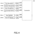
- FIG. 4 is an example of the hardware configuration diagram of the audio input/output device according to the FIG. 1 .
- An audio input/output device can receive audio inputs from a user via audio collection units, such as microphones or particularly MEMS microphones, can process the received audio inputs for noise-cancellation, and can generate audio output via speakers.
- the device according to the present advancement can, in one instance, serve as a wearable music player in which the user controls the music player using voice commands via microphones, while the music is output by the speakers.
- the device according to the present advancement can be remotely connected to a server and can serve as a communications device that sends queries to the server for obtaining information or sends voice commands to control other devices connected to the server, while the information retrieved from the server is output by the speakers.
- FIG. 1 illustrates one embodiment of an exemplary audio input/output device 1 according to the present disclosure.
- the audio input/output device 1 includes a U-shaped casing 10 (an example of “frame” according to the appended claims), and as shown in FIG. 3 , the device 1 includes four microphones 14 (an example of “audio collection unit” according to the appended claims) and two speakers 24 in the U-shaped casing 10 .
- the U-shaped casing 10 when mounted to the user, can be arranged around the user's neck, with the open end of the U-shape being positioned on a front-side of the user and the closed end of the U-shape being positioned on a rear-side of the user.
- the open end of the U-shape can be closer to the user's mouth in this embodiment than the closed end.
- the four microphones 14 namely a first microphone 14 A, a second microphone 14 B, a third microphone 14 C, and a fourth microphone 14 D, and the two speakers 14 , namely a first speaker 24 A and a second speaker 24 B, are provided in the casing 10 and separately from each other.
- the microphones 14 are provided within the casing 10
- voice intake holes 12 are provided on an upper surface of the casing 10 so as to allow audio signals to be received by the microphones 14 .
- voice intake holes 12 A, 12 B, 12 C, 12 D are respectively provided on the upper surface of the casing 10 to correspond to the first microphone 14 A, the second microphone 14 B, the third microphone 14 C, and the fourth microphone 14 D.
- audio outlet holes 22 A and 22 B are respectively provided on the upper surface of the casing 10 to correspond to the first speaker 24 A and the second speaker 24 B so as to allow audio outputs to be transmitted from the speakers 24 A and 24 B to the user.
- the first microphone 14 A is arranged near the open end of the U-shaped casing 10 and is closer to the user's mouth than the second microphone 14 B is, and the first speaker 24 A is positioned between the first microphone 14 A and second microphone 14 B.
- the first speaker 24 A can be positioned in such a way that the distance to the first microphone 14 A and the distance to the second microphone 14 B are substantially the same; however, the two distances do not have to be the same.
- the first microphone 14 A is capable of receiving audio inputs, such as voice inputs from the user, whereas the second microphone 14 B can receive other audio inputs to be used for noise-cancelling.
- the arrangement of the first microphone 14 A, the first speaker 24 A, and the second microphone 14 B, in this order, allows effective noise-cancelling to be achieved.
- the third microphone 14 C, the second speaker 24 B, and the fourth microphone 14 D are arranged in this order to achieve effective noise-cancelling.
- the third microphone 14 C is arranged near the open end of the U-shaped casing 10 closer to the user's mouth and is capable of receiving audio inputs, such as voice inputs from the user
- the fourth microphone 14 D is arranged further from the user's mouth to receive other audio inputs to be used for noise-cancelling
- the second speaker 24 B is positioned between the third microphone 14 C and the fourth microphone 14 D.
- the wearable audio input/output device 1 includes a controller 30 having an internal processing unit, such as a CPU, for audio processing.
- the controller 30 receives respective audio inputs via the microphones 14 , the controller 30 can perform noise-cancellation based on the received audio inputs. Thereafter, the controller 30 , based on the post-noise-cancellation audio inputs, identifies and recognizes the voice inputs of the user and controls the device 1 according to the voice inputs, e.g.
- the controller 30 can perform noise-cancellation based on the received audio inputs from the microphones 14 and then send the post-noise-cancellation audio inputs to a server via a communications unit (not shown in Figures) to be analyzed or processed.
- the controller 30 can be composed of one or more IC components, such as an Audio Processor and Controller and an Application Processor.
- the controller 30 can be connected to the microphones 14 and speakers 24 via IC components such as A/D converter(s) 32 , D/A converter(s) 34 , amplifier(s) (not shown in Figures), etc.
- four microphones 14 are provided to receive audio inputs. However, depending on the mode of usage, one or more microphones can be omitted. For example, in one different embodiment, the third microphone 14 C and the fourth microphone 14 D can be omitted. In this case, the first microphone 14 A and the second microphone 14 B will receive audio inputs and processing such as noise-cancellation and audio recognition can be performed based on the inputs from the two microphones 14 A, 14 B. Similarly, in the embodiment described above and shown in FIG. 1 , two speakers 24 A and 24 B are provided; however, the second speaker 24 B can be omitted.
- the second microphone 14 B and the fourth microphone 14 D are each provided for noise cancellation.
- one microphone can be provided to achieve the functions of both of the microphones 14 B and 14 D.
- one microphone can serve both as the second microphone 14 B and the fourth microphone 14 D for noise cancellation.
- this one microphone can be arranged in the U-shaped casing 10 on the rear-side of the user, further from the open end of the U-shaped casing and further from the user's mouth than the first microphone 14 A and the third microphone 14 C.
- the second microphone 14 B and the fourth microphone 14 D can each be represented by a group of microphones for noise cancellation. In this arrangement, all of the individual microphones in each group can be arranged further from the open end of the U-shaped casing 10 than the first microphone 14 A and the third microphone 14 C.
- the first speaker 24 A and the second speaker 24 B serve as speakers that generate audio outputs.
- the first speaker 24 A and the second speaker 24 B can be configured to also include functions other than audio output.
- the speakers can be configured such that they can also include functions of a vibration sensor or a microphone.
- the frame is a U-shaped casing that can be mounted to a user around the user's neck.
- the casing or the frame on which the microphones and speakers are arranged can also be in a different shape that goes around the user's neck, or it can be shaped as a headband that can be mounted around the user's head or a clip-on that can be mounted on the user's ear.
- the audio input/output device 1 can further include input means to receive user's non-audio inputs to control various functions of the device 1 .
- input buttons can be provided on the casing to receive inputs associated with ON/OFF of the device, volume of the speakers, etc.
Abstract
Description
Claims (6)
Priority Applications (1)
| Application Number | Priority Date | Filing Date | Title |
|---|---|---|---|
| US16/233,086 US10602274B2 (en) | 2018-01-05 | 2018-12-27 | Audio input/output device |
Applications Claiming Priority (2)
| Application Number | Priority Date | Filing Date | Title |
|---|---|---|---|
| US201862613770P | 2018-01-05 | 2018-01-05 | |
| US16/233,086 US10602274B2 (en) | 2018-01-05 | 2018-12-27 | Audio input/output device |
Publications (2)
| Publication Number | Publication Date |
|---|---|
| US20190215608A1 US20190215608A1 (en) | 2019-07-11 |
| US10602274B2 true US10602274B2 (en) | 2020-03-24 |
Family
ID=67140003
Family Applications (1)
| Application Number | Title | Priority Date | Filing Date |
|---|---|---|---|
| US16/233,086 Active US10602274B2 (en) | 2018-01-05 | 2018-12-27 | Audio input/output device |
Country Status (2)
| Country | Link |
|---|---|
| US (1) | US10602274B2 (en) |
| JP (1) | JP2019122035A (en) |
Families Citing this family (4)
| Publication number | Priority date | Publication date | Assignee | Title |
|---|---|---|---|---|
| US11388515B2 (en) * | 2014-06-22 | 2022-07-12 | Walter Lancaster | Daisy chained audio speaker system |
| JP1674399S (en) * | 2019-01-09 | 2020-12-07 | ||
| JP7408414B2 (en) * | 2020-01-27 | 2024-01-05 | シャープ株式会社 | wearable microphone speaker |
| JP6786139B1 (en) * | 2020-07-06 | 2020-11-18 | Fairy Devices株式会社 | Voice input device |
Citations (2)
| Publication number | Priority date | Publication date | Assignee | Title |
|---|---|---|---|---|
| US6091832A (en) * | 1996-08-12 | 2000-07-18 | Interval Research Corporation | Wearable personal audio loop apparatus |
| US20180286376A1 (en) * | 2015-10-13 | 2018-10-04 | Sony Corporation | Information processing device |
-
2018
- 2018-12-20 JP JP2018237940A patent/JP2019122035A/en active Pending
- 2018-12-27 US US16/233,086 patent/US10602274B2/en active Active
Patent Citations (2)
| Publication number | Priority date | Publication date | Assignee | Title |
|---|---|---|---|---|
| US6091832A (en) * | 1996-08-12 | 2000-07-18 | Interval Research Corporation | Wearable personal audio loop apparatus |
| US20180286376A1 (en) * | 2015-10-13 | 2018-10-04 | Sony Corporation | Information processing device |
Also Published As
| Publication number | Publication date |
|---|---|
| US20190215608A1 (en) | 2019-07-11 |
| JP2019122035A (en) | 2019-07-22 |
Similar Documents
| Publication | Publication Date | Title |
|---|---|---|
| US10602274B2 (en) | Audio input/output device | |
| WO2020220735A1 (en) | Acoustic output device | |
| EP2202998B1 (en) | A device for and a method of processing audio data | |
| JP5315506B2 (en) | Method and system for bone conduction sound propagation | |
| US10803857B2 (en) | System and method for relative enhancement of vocal utterances in an acoustically cluttered environment | |
| CN111902866A (en) | Echo control in a binaural adaptive noise cancellation system in a headphone | |
| US9934774B1 (en) | Noise-cancelling earphone | |
| EP2882203A1 (en) | Hearing aid device for hands free communication | |
| US20130315415A1 (en) | Ear microphone and voltage control device for ear micrrophone | |
| JP2009530950A (en) | Data processing for wearable devices | |
| JPH07506948A (en) | Unidirectional ear microphone and method | |
| WO2006028587A3 (en) | Headset for separation of speech signals in a noisy environment | |
| EA002838B1 (en) | Head phone | |
| WO2020137654A1 (en) | Sound input/output device, hearing aid, sound input/output method, and sound input/output program | |
| JP2002358089A (en) | Method and device for speech processing | |
| US10529358B2 (en) | Method and system for reducing background sounds in a noisy environment | |
| CN108200492A (en) | Voice control optimization method, device and the earphone and wearable device that integrate In-Ear microphone | |
| US11330366B2 (en) | Portable device comprising a directional system | |
| CN114390419A (en) | Hearing device including self-voice processor | |
| US11290802B1 (en) | Voice detection using hearable devices | |
| KR200426390Y1 (en) | Earphone having microphone | |
| US11533555B1 (en) | Wearable audio device with enhanced voice pick-up | |
| WO2019119376A1 (en) | Earphone and method for uplink cancellation of an earphone | |
| JP2019110447A (en) | Electronic device, control method of electronic device, and control program of electronic device | |
| US10540955B1 (en) | Dual-driver loudspeaker with active noise cancellation |
Legal Events
| Date | Code | Title | Description |
|---|---|---|---|
| AS | Assignment |
Owner name: DSP GROUP LTD., ISRAEL Free format text: ASSIGNMENT OF ASSIGNORS INTEREST;ASSIGNORS:TAKESHIMA, YOSHITADA;LVOV, DMITRI;CHEN, YAAKOV;REEL/FRAME:047855/0627 Effective date: 20181220 Owner name: ONKYO CORPORATION, JAPAN Free format text: ASSIGNMENT OF ASSIGNORS INTEREST;ASSIGNORS:TAKESHIMA, YOSHITADA;LVOV, DMITRI;CHEN, YAAKOV;REEL/FRAME:047855/0627 Effective date: 20181220 |
|
| FEPP | Fee payment procedure |
Free format text: ENTITY STATUS SET TO UNDISCOUNTED (ORIGINAL EVENT CODE: BIG.); ENTITY STATUS OF PATENT OWNER: LARGE ENTITY |
|
| STPP | Information on status: patent application and granting procedure in general |
Free format text: NON FINAL ACTION MAILED |
|
| STPP | Information on status: patent application and granting procedure in general |
Free format text: NOTICE OF ALLOWANCE MAILED -- APPLICATION RECEIVED IN OFFICE OF PUBLICATIONS |
|
| STPP | Information on status: patent application and granting procedure in general |
Free format text: PUBLICATIONS -- ISSUE FEE PAYMENT VERIFIED |
|
| STCF | Information on status: patent grant |
Free format text: PATENTED CASE |
|
| MAFP | Maintenance fee payment |
Free format text: PAYMENT OF MAINTENANCE FEE, 4TH YEAR, LARGE ENTITY (ORIGINAL EVENT CODE: M1551); ENTITY STATUS OF PATENT OWNER: LARGE ENTITY Year of fee payment: 4 |
|
| AS | Assignment |
Owner name: ONKYO CORPORATION, JAPAN Free format text: ASSIGNMENT OF ASSIGNORS INTEREST;ASSIGNOR:ONKYO HOME ENTERTAINMENT CORPORATION;REEL/FRAME:066074/0383 Effective date: 20231219 |
|
| AS | Assignment |
Owner name: ONKYO CORPORATION, JAPAN Free format text: CORRECTIVE ASSIGNMENT TO CORRECT THE SPELLING OF ASSIGNEE ADDRESS SHOULD BE CHUO-KU NOT CHOU-KU PREVIOUSLY RECORDED ON REEL 066074 FRAME 0383. ASSIGNOR(S) HEREBY CONFIRMS THE ASSIGNMENT;ASSIGNOR:ONKYO HOME ENTERTAINMENT CORPORATION;REEL/FRAME:066343/0076 Effective date: 20231219 |