US10601658B2 - Maintenance of consumable physical components of a network - Google Patents
Maintenance of consumable physical components of a network Download PDFInfo
- Publication number
- US10601658B2 US10601658B2 US14/681,651 US201514681651A US10601658B2 US 10601658 B2 US10601658 B2 US 10601658B2 US 201514681651 A US201514681651 A US 201514681651A US 10601658 B2 US10601658 B2 US 10601658B2
- Authority
- US
- United States
- Prior art keywords
- maintenance
- consumable physical
- consumable
- physical components
- event trigger
- Prior art date
- Legal status (The legal status is an assumption and is not a legal conclusion. Google has not performed a legal analysis and makes no representation as to the accuracy of the status listed.)
- Active, expires
Links
Images


Classifications
-
- H—ELECTRICITY
- H04—ELECTRIC COMMUNICATION TECHNIQUE
- H04L—TRANSMISSION OF DIGITAL INFORMATION, e.g. TELEGRAPHIC COMMUNICATION
- H04L41/00—Arrangements for maintenance, administration or management of data switching networks, e.g. of packet switching networks
- H04L41/08—Configuration management of networks or network elements
- H04L41/085—Retrieval of network configuration; Tracking network configuration history
- H04L41/0853—Retrieval of network configuration; Tracking network configuration history by actively collecting configuration information or by backing up configuration information
-
- F—MECHANICAL ENGINEERING; LIGHTING; HEATING; WEAPONS; BLASTING
- F24—HEATING; RANGES; VENTILATING
- F24F—AIR-CONDITIONING; AIR-HUMIDIFICATION; VENTILATION; USE OF AIR CURRENTS FOR SCREENING
- F24F8/00—Treatment, e.g. purification, of air supplied to human living or working spaces otherwise than by heating, cooling, humidifying or drying
- F24F8/10—Treatment, e.g. purification, of air supplied to human living or working spaces otherwise than by heating, cooling, humidifying or drying by separation, e.g. by filtering
-
- G—PHYSICS
- G06—COMPUTING; CALCULATING OR COUNTING
- G06Q—INFORMATION AND COMMUNICATION TECHNOLOGY [ICT] SPECIALLY ADAPTED FOR ADMINISTRATIVE, COMMERCIAL, FINANCIAL, MANAGERIAL OR SUPERVISORY PURPOSES; SYSTEMS OR METHODS SPECIALLY ADAPTED FOR ADMINISTRATIVE, COMMERCIAL, FINANCIAL, MANAGERIAL OR SUPERVISORY PURPOSES, NOT OTHERWISE PROVIDED FOR
- G06Q10/00—Administration; Management
- G06Q10/06—Resources, workflows, human or project management; Enterprise or organisation planning; Enterprise or organisation modelling
- G06Q10/063—Operations research, analysis or management
- G06Q10/0631—Resource planning, allocation, distributing or scheduling for enterprises or organisations
-
- G—PHYSICS
- G06—COMPUTING; CALCULATING OR COUNTING
- G06Q—INFORMATION AND COMMUNICATION TECHNOLOGY [ICT] SPECIALLY ADAPTED FOR ADMINISTRATIVE, COMMERCIAL, FINANCIAL, MANAGERIAL OR SUPERVISORY PURPOSES; SYSTEMS OR METHODS SPECIALLY ADAPTED FOR ADMINISTRATIVE, COMMERCIAL, FINANCIAL, MANAGERIAL OR SUPERVISORY PURPOSES, NOT OTHERWISE PROVIDED FOR
- G06Q10/00—Administration; Management
- G06Q10/20—Administration of product repair or maintenance
-
- H—ELECTRICITY
- H04—ELECTRIC COMMUNICATION TECHNIQUE
- H04L—TRANSMISSION OF DIGITAL INFORMATION, e.g. TELEGRAPHIC COMMUNICATION
- H04L41/00—Arrangements for maintenance, administration or management of data switching networks, e.g. of packet switching networks
- H04L41/14—Network analysis or design
- H04L41/145—Network analysis or design involving simulating, designing, planning or modelling of a network
-
- H—ELECTRICITY
- H04—ELECTRIC COMMUNICATION TECHNIQUE
- H04L—TRANSMISSION OF DIGITAL INFORMATION, e.g. TELEGRAPHIC COMMUNICATION
- H04L41/00—Arrangements for maintenance, administration or management of data switching networks, e.g. of packet switching networks
- H04L41/14—Network analysis or design
- H04L41/147—Network analysis or design for predicting network behaviour
-
- H—ELECTRICITY
- H04—ELECTRIC COMMUNICATION TECHNIQUE
- H04L—TRANSMISSION OF DIGITAL INFORMATION, e.g. TELEGRAPHIC COMMUNICATION
- H04L43/00—Arrangements for monitoring or testing data switching networks
- H04L43/08—Monitoring or testing based on specific metrics, e.g. QoS, energy consumption or environmental parameters
- H04L43/0805—Monitoring or testing based on specific metrics, e.g. QoS, energy consumption or environmental parameters by checking availability
- H04L43/0817—Monitoring or testing based on specific metrics, e.g. QoS, energy consumption or environmental parameters by checking availability by checking functioning
-
- F—MECHANICAL ENGINEERING; LIGHTING; HEATING; WEAPONS; BLASTING
- F24—HEATING; RANGES; VENTILATING
- F24F—AIR-CONDITIONING; AIR-HUMIDIFICATION; VENTILATION; USE OF AIR CURRENTS FOR SCREENING
- F24F11/00—Control or safety arrangements
- F24F11/30—Control or safety arrangements for purposes related to the operation of the system, e.g. for safety or monitoring
-
- F24F3/1603—
Definitions
- the present disclosure relates generally to maintaining networking equipment, and in particular, to maintaining consumable physical components of networking equipment.
- IoE Internet of Everything
- Replacing or repairing a consumable physical component before it malfunctions or before the performance of an associated networking component has fallen below an acceptable level may result in unnecessary costs.
- the operations costs associated with maintaining consumable physical components can rise to a burdensome level.
- FIG. 1 is a block diagram of a system of maintaining consumable physical components of networking equipment in accordance with some implementations.
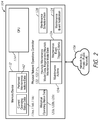
- FIG. 2 is a block diagram of a physical network operations controller in accordance with some implementations.
- FIG. 3 is a block diagram depicting the operation of a physical network operations controller that is transmitting a maintenance event trigger criteria in accordance with some implementations.
- FIG. 4 is a block diagram depicting the operation of a physical network operations controller that is transmitting a maintenance event notification in accordance with some implementations.
- FIG. 5 is a block diagram depicting the operation of a consumable physical component that is responsively transmitting operating status data in accordance with some implementations.
- FIG. 6 is a perspective view of a consumable physical component in accordance with some implementations.
- FIG. 7 is a front view of the consumable physical component of FIG. 6 in accordance with some implementations.
- FIG. 8 is a block diagram depicting an arrangement of a consumable physical component in accordance with some implementations.
- FIG. 9 is a block diagram depicting the operation of a consumable physical component that is receiving maintenance action data according to some implementations.
- FIG. 10 is a block diagram depicting the operation of a consumable physical component that is transmitting operating status data according to some implementations.
- FIG. 11 is a flowchart representation of a method of maintaining consumable physical components in a network according to some implementations.
- FIG. 12 is a flowchart representation of a continuation of the method depicted in FIG. 11 in accordance with some implementations.
- FIG. 13 is a flowchart representation of a continuation of the method depicted in FIGS. 11 and 12 in accordance with some implementations.
- FIG. 14 is a flowchart representation of a continuation of the method depicted in FIGS. 11-13 in accordance with some implementations.
- FIG. 15 is a block diagram of a physical network controller in accordance with some implementations.
- FIG. 16 is a block diagram of a consumable physical component in accordance with some implementations.
- a system of maintaining consumable physical components of networking equipment includes at least one notification device and a physical network operations controller configured to communication with the at least one notification device.
- the physical network operations controller is also configured to communication with a plurality of consumable physical components for networking equipment.
- the physical network operations controller includes a memory device and a controller interconnected with the memory device. The controller is configured to obtain current operating status data for the plurality of the consumable physical components for storage at the memory device and generate historical operating status data for the plurality of consumable physical components based on the stored current operating status data.
- the controller is further configured to generate heuristic maintenance model data for the plurality of consumable physical components based on at least one of the current operating status data and the historical operating status data.
- the heuristic maintenance model data defines maintenance actions and maintenance event trigger criteria for the plurality of consumable physical components.
- the controller generates maintenance schedule data for the plurality of the consumable physical components based on the heuristic maintenance model data.
- the controller determines that at least one of the maintenance event trigger criteria is met in respect of at least one of the plurality of consumable physical components.
- the controller In response to determining that the at least one maintenance event trigger criteria is met, the controller generates a maintenance event notification, and transmits the maintenance event notification to the at least one notification device.
- the controller transmits to the at least one of the plurality of consumable physical components maintenance action data that indicates at least one of the maintenance actions to be performed based on the at least one of the maintenance event trigger criteria being met.
- a multi-layered approach includes a Manual Layer, an Automation Layer, an Enterprise Resource Planning (ERP) Layer and a Long-Term Planning (LTP) Layer.
- ERP Enterprise Resource Planning
- LTP Long-Term Planning
- the Manual Layer includes maintenance-related activities performed by maintenance personnel, such as visually inspecting, manually repairing and replacing the consumable physical components.
- the Automation Layer includes maintenance-related activities performed by the consumable physical component.
- the consumable physical component transmits data to a physical network operations controller indicating a current operating status of the consumable physical component.
- the current operating status includes information about the lifespan or failure of a subcomponent of the consumable physical component, the current power consumption of the consumable physical component and information about the current operating environment of the consumable physical component.
- the current operating status also identifies the consumable physical component and any other associated consumable physical components (e.g., associated by component type and/or proximity).
- the consumable physical component is configured to address certain maintenance issues.
- the consumable physical component is an air filter that is configured to recognize when the filter media has reached a selected maintenance threshold of 80 percent occlusion and requires changing.
- the example air filter is also configured to replace the occluded filter media with fresh filter media.
- the consumable physical component is configured to send a notification to the physical network operations controller when a maintenance task is required to be performed on the consumable physical component.
- the ERP Layer oversees the maintenance activities of the Manual Layer and the Automation Layer via the physical network operations controller. In some implementations, the ERP Layer generates maintenance tasks, maintenance schedules and the criteria for triggering a maintenance event, such as the failure of a consumable physical component. The ERP Layer also directs the consumable physical components and, in some implementations, the maintenance personnel to perform the maintenance activities. The ERP Layer obtains the data indicating a current operating status of the consumable physical component and uses the data to generate historical operating data of the consumable physical component. The current operating status may be obtained from the consumable physical component and/or an associated sensor (e.g., a thermal or airflow rate sensor).
- an associated sensor e.g., a thermal or airflow rate sensor
- the ERP Layer also generates heuristic maintenance models based on the historical operating data and real-time operating data (e.g., current operating status data) of the consumable physical component.
- the heuristic maintenance models may aggregate some maintenance tasks or delay performance of a particular maintenance task in order to reduce operating costs and more efficiently use maintenance personnel or consumables resources.
- the current operating status of a fan may indicate the fan's motor is broken.
- the ERP Layer may poll thermal sensors and other fans in the vicinity of the broken fan (e.g., proximate to the broken fan) to determine if a selected thermal limit has been reached or if the current operating status of the other fans indicates an impending maintenance event. If the selected thermal limit has not been reached or there is no indication of an impending maintenance event, the ERP Layer may delay replacement of the broken fan.
- the LTP Layer tracks the maintenance activities performed by the ERP Layer, the Automation Layer and the Manual Layer. In some implementations, the LTP Layer analyzes the maintenance activities of the ERP Layer, Automation Layer and the Manual Layer over a period of time to determine maintenance “hot-spots” among the consumable physical components of the networking equipment. For example, in some implementations, the LTP layer determines patterns in maintenance activities for groups of the consumable physical components. In some implementations, the LTP Layer tracks the costs associated with the performed maintenance activities and regenerates the heuristic maintenance models used by the ERP Layer to take into account those costs.
- Consumable physical components include physical components that support the operation of networking equipment, such as servers, controllers, switches and routers, and are typically repaired or replaced over the lifetime of the networking equipment. Examples of consumable or items often most commonly replaced during service life of physical components include fans, air filters, and power supplies.
- FIG. 1 depicts a system 100 configured to maintain consumable physical components of networking equipment in accordance with some implementations.
- the system 100 includes at least one notification device, such as the notification devices 102 a and 102 b , and a physical network operations controller 104 .
- the physical network operations controller 104 is configured to communicate with the notification devices 102 a and 102 b over a network 106 via communication links 108 a , 108 b and 108 c .
- the network 106 includes the Internet or any other suitable combination of wired and/or wireless communication networks.
- the network 106 is a private network and, in other implementations, the network 106 is a public network.
- the communication links 108 a , 108 b and 108 c include any combination of wired and/or wireless communication links suitable for the communication of at least data between the physical network operations controller 104 and the notification devices 102 a and 102 b .
- the physical network operations controller 104 is also configured to communicate with a plurality of consumable physical components of networking equipment, such as consumable physical components 110 a , 110 b and 110 c (also referred to individually as the consumable physical component 110 a , the consumable physical component 110 b and the consumable physical component 110 c , and as a group as the consumable physical components 110 ), over the network 106 and via communication links 108 c , 108 d , 108 e and 108 f .
- the communication links 108 c , 108 d , 108 e and 108 f include any combination of wired and/or wireless communication links suitable for the communication of at least data between the physical network operations controller 104 and the consumable physical components 110 a , 110 b and 110 c .
- the communication between the physical network operations controller 104 and the consumable physical components 110 is bi-directional in that the physical network operations controller 104 is configured to transmit data to and to receive data from the consumable physical components 110 , and vice-versa.
- the physical network operations controller 104 includes a memory device 112 and controller interconnected with the memory device 112 , such as Central Processing Unit (CPU) 114 .
- CPU Central Processing Unit
- FIGS. 1 and 2 the physical network operations controller 104 is depicted as a single computing device, such as a server. However, in some implementations, the physical network operations controller 104 includes multiple computing devices, some of which may be remote from other computing devices of the physical network operations controller 104 .
- the physical network operations controller 104 performs the maintenance-related activities of the ERP Layer and the LTP Layer. As shown in FIGS. 1 to 5 , the CPU 114 is configured to obtain the current operating status data 116 a , 116 b and 116 c of the consumable physical components 110 .
- the current operating status data 116 a , 116 b and 116 c includes data that indicates the operating or maintenance status of at least a subcomponent, such as a fan motor, of the consumable physical components 110 .
- the current operating status data 116 a , 116 b and 116 c includes at least one of the power consumption, the energy usage, a component identifier, a component type and a remaining expected lifespan for each one of the consumable physical components 110 .
- the CPU 114 polls or requests the current operating status data 116 a , 116 b and 116 c from one or more of the consumable physical components 110 .
- one or more of the consumable physical components 110 transmits the current operating status data 116 a , 116 b and 116 c to the physical network operations controller 104 .
- the CPU 114 obtains the current operating status data 116 a , 116 b and 116 c by a combination of polling the consumable physical components 110 and transmissions of the current operating status data 116 a , 116 b and 116 c from one or more of the consumable physical components 110 .
- the current operating status data 116 a , 116 b and 116 c is obtained in real-time from the consumable physical components 110 .
- the current operating status data 116 a , 116 b and 116 c is stored in the memory device 112 .
- the CPU 114 is configured to generate historical operating status data 120 a , 120 b and 120 c for the consumable physical components 110 ( FIG. 2 ).
- the CPU 114 is also configured to generate heuristic maintenance models, in the form of heuristic maintenance model data 122 , based on at least one of the current operating status data 116 a , 116 b and 116 c and the historical operating status data 120 a , 120 b and 120 c of the consumable physical components 110 .
- the heuristic maintenance model data 122 takes into account various maintenance priorities, such as avoiding the failure of a threshold number of the consumable physical components 110 and staying below a desired power consumption limit for the consumable physical components 110 , and patterns in the maintenance activities in respect of one or more of the consumable physical components 110 .
- the heuristic model data 122 takes into account how regularly the consumable physical component 110 a has been repaired over a period of time.
- the consumable physical components 110 there is at least one sensor associated with the consumable physical components 110 .
- the consumable physical components 110 are associated with sensors 118 a , 118 b and 118 c , respectively.
- the sensors 118 a , 118 b and 118 c are any combination of sensors suitable for detecting operating environmental conditions or performance indicators that are indicative of an operating status of at least one of the consumable physical components 110 .
- the consumable physical component 110 b is a fan and the sensor 118 b is a thermal sensor configured to determine the temperature of the air surrounding the consumable physical component 110 b .
- the sensor 118 b If the consumable physical component 110 b fan has failed (e.g., stopped running), then the sensor 118 b , as a thermal sensor, will likely register a higher than normal air temperature reading. Since data from the sensors 118 a , 118 b and 118 c can provide useful information in determining the current operating status of the consumable physical components 110 , in some implementations, the CPU 114 is configured to obtain the current operating status data 116 a , 116 b and 116 c from at least one of the sensors 118 a , 118 b and 118 c .
- the CPU 114 is configured to obtain the current operating status data 116 a , 116 b and 116 c by polling at least one of the consumable physical components 110 and at least one of the sensors 118 a , 118 b and 118 c.
- the heuristic maintenance model data 122 defines maintenance actions 124 and maintenance trigger criteria 126 for the consumable physical components 110 .
- the maintenance actions 124 include any action that is to be performed by any one of the consumable physical components 110 , the maintenance personnel and the physical network operations controller 104 to repair, replace or otherwise maintain the consumable physical components 110 .
- the heuristic maintenance model data 122 defines at least one relationship between the maintenance actions 124 .
- the consumable physical component 110 a is an air filter and the consumable physical component 110 b is a nearby fan (e.g., the consumable physical component 110 a and the consumable physical component 110 b are located in the same region of a data center 132 ).
- the historical operating status data 120 a , 120 b indicates that when the consumable physical component 110 a air filter becomes fully blocked the consumable physical component 110 b fan usually consumes power close to a threshold power consumption limit, it may be proactive to relate the maintenance actions of replacing the filter media for the consumable physical component 110 a air filter with inspecting the consumable physical component 110 b fan in order to perform the maintenance actions together.
- the maintenance event trigger criteria 126 include the operating conditions of one or more of the consumable physical components 110 that must be met in order to initiate maintenance actions in respect of one or more of the consumable physical components 110 .
- the maintenance event trigger criteria 126 includes at least one of an indication of an operational failure of at least one subcomponent of the consumable physical components 110 , an indication that the expected lifespan of at least one subcomponent of the consumable physical components 110 has been reached, an indication that a selected thermal limit of at least one of the consumable physical components 110 has been reached, an indication that a performance level of the at least one of the consumable physical components 110 is below a selected threshold limit, and a scheduled maintenance event for at least one of the consumable physical components 110 is due.
- the heuristic maintenance model data 122 is also used by the CPU 114 to generate maintenance schedule data 128 for the consumable physical components 110 .
- the frequency with which a particular subcomponent of the consumable physical component 110 b fails will likely impact how often the consumable physical component 110 b is inspected or a replacement subcomponent is to be ordered for the consumable physical component 110 b .
- the maintenance event trigger criteria 126 takes into account relative weights between different maintenance priorities. For example, in some implementations, avoiding a power consumption limit by a particular one of the consumable physical components 110 is of greater importance than ensuring the expected lifespan of all of the consumable physical components 110 is reached before replacing or repairing any of the consumable physical components 110 .
- the CPU 114 is also configured to determine that at least one of the maintenance event trigger criteria 126 is met in respect of at least one of the consumable physical components 110 . For example, in some implementations, the CPU 114 compares the obtained current operating status data 116 a , 116 b and 116 c against the maintenance event trigger criteria 126 . In some other implementations, the CPU 114 transmits the maintenance event trigger criteria 126 to the consumable physical components 110 ( FIG. 3 ) and each one of the consumable physical components 110 determines whether the maintenance event trigger criteria 126 is met.
- the consumable physical component 110 c compares the maintenance event trigger criteria 126 to the current operating status data 116 c and determines the maintenance event trigger criteria 126 is met (e.g., performance of a maintenance activity is required in respect of the consumable physical component 116 c ).
- the consumable physical component 110 c transmits notification data 130 that indicates at least one of the maintenance event trigger criteria 126 is met in respect of the consumable physical component 116 c .
- the notification data 130 includes an indication of which of the maintenance event trigger criteria 126 is met in respect of the consumable physical component 116 c .
- the CPU 114 determines that at least one of the maintenance event trigger criteria 126 is met, particularly in respect of the consumable physical component 116 c , by receiving the notification data 130 .
- the CPU 114 In response to determining that at least one of the maintenance event trigger criteria 126 is met in respect of at least one of the consumable physical components 110 (e.g., in respect of the consumable physical component 110 c ), the CPU 114 is configured to generate a maintenance event notification 134 ( FIG. 2 ) and to transmit the maintenance event notification 134 to at least one of the notification devices 102 a and 102 b . As shown in FIG. 4 , the maintenance event notification 134 is transmitted to the notification device 102 a .
- the maintenance event notification 134 is transmitted to is based on the responsibilities or capabilities of the maintenance personnel accessing the notification devices 102 a and 102 b and the nature of the maintenance event (e.g., the maintenance event notification requiring replacement of a consumable physical component fan would be transmitted to a notification device accessed by the maintenance personnel charged with repairing and/or replacing fans).
- the maintenance event notification 134 is data suitable for providing a notification of the maintenance event at the notification device, such as a Short Message Service (SMS) text message and an email message to an email address that is accessible by the notification device.
- SMS Short Message Service
- the maintenance event notification 134 indicates the consumable physical component requiring maintenance (e.g., the consumable physical component 110 c ) and at least one maintenance action to be performed in respect of the maintenance event trigger criteria 126 being met, either by the maintenance personnel accessing the notification device, the physical network operations controller 104 (e.g., order a replacement consumable physical component for the consumable physical component 110 c , visually inspect the consumable physical component 110 c ) or, in some implementations, by the consumable physical component 110 c .
- the notification devices 102 a and 102 b include any computing device suitable for receiving and providing the maintenance event notification 134 in a format for review by the maintenance personnel accessing the notification devices 102 a and 102 b .
- the notification devices 102 a and 102 b include displays 136 a and 136 b for displaying the maintenance event notification 134 .
- the CPU 114 is also configured to transmit maintenance action data 138 to the consumable physical component 110 c that indicates at least one of the maintenance actions that is to be performed based on the at least one maintenance event trigger criteria 126 that was met. For example, in some implementations, at least one of the maintenance actions to be performed by the consumable physical component 110 c is to shut down during a specified time period in anticipation of service performed by maintenance personnel. Additionally, the CPU 114 may also transmit a command for consumable physical component 110 c to display a status indication signifying a “shut down” or “maintenance required” state.
- Associating or grouping one or more of the consumable physical components 110 together may be helpful for determining effective maintenance models, particularly in respect of aggregation of maintenance actions.
- one or more of the consumable physical components 110 are associated with each other (e.g., the consumable physical components 110 includes at least one group of associate consumable physical components).
- the consumable physical components 110 a and 110 b are located in the same region of data center 132 .
- the consumable physical components 110 a and 110 b would then form at least one group of associated consumable physical components.
- the association between one or more of the consumable physical components 110 may also be in respect of a component type (e.g., all of the fans are associated with each other), expected lifespan or any other suitable basis for grouping one or more of the consumable physical components, such as a location or proximity of one or more of the components 110 to each other.
- the current operating status data 116 a , 116 b and 116 c includes at least one of a group identifier, a component location and a component type.
- the physical network operations controller 104 in response to determining that the maintenance event trigger criteria 126 is met in respect of one or more of the consumable physical components 110 , the physical network operations controller 104 reassesses the current operating state of other associated consumable physical components before generating the maintenance event notification 134 .
- the current operating state of associated components may be helpful in determining the scope of the maintenance actions required to address the maintenance event trigger criteria 126 being met by any particular one of the consumable physical components 110 .
- the consumable physical component 110 a is an air filter and the consumable physical component 110 b is a fan located in the same region of a data center 132 and are members of at least one group of associated consumable physical components (e.g., associated by location).
- the CPU 114 Upon determining the maintenance event trigger criteria 126 is met in respect of at least one member of a group of associated consumable physical components, the CPU 114 is configured to obtain follow-up operating status data for at least one remaining member of the group of associated consumable physical components. For example, upon determining the maintenance event trigger criteria 126 is met in respect of the consumable physical component 110 a air filter, the CPU 114 polls the associated consumable physical component 110 b in order to obtain follow-up operating status data 140 of the consumable physical component 110 b ( FIG. 5 ) and determine whether a maintenance event is imminent for the consumable physical component 110 b.
- the physical network operations controller 104 tracks and analyzes the maintenance activities of the ERP Layer, Automation Layer and the Manual Layer to determine patterns in the maintenance activities and identify maintenance “hotspots” or areas of improvement for ongoing maintenance of the consumable physical components 110 .
- the CPU 114 is configured to store at the memory device 112 , as performed maintenance actions data 142 ( FIG. 2 ), the maintenance actions performed in response to the maintenance event trigger criteria 126 being met in respect of one or more of the consumable physical components 110 .
- the performed maintenance actions data 142 may be in respect of maintenance actions performed over a selected period of time.
- the CPU 114 is also configured to determine the costs associated with performing the maintenance actions (e.g., cumulative labor costs and replacement consumable physical component costs) and regenerate the heuristic maintenance model data 122 based on the stored performed maintenance actions data 142 and the determined costs associated with performing the maintenance actions.
- the regenerated heuristic maintenance model data 122 - 1 ( FIG. 2 ) takes into account the determined costs as well as the other considerations discussed above.
- one or more of the consumable physical components 110 is configured to perform one or more of the maintenance actions indicated by the maintenance action data 138 without intervention by the maintenance personnel (i.e. one or more of the maintenance actions is self-addressable by one or more of the consumable physical components 110 ).
- the consumable physical component 110 c is an air filter that is configured to replace the used or occluded filter media with fresh filter media.
- the CPU 114 is configured to determine at least one of the maintenance actions indicated by the maintenance action data 138 (e.g., replacing the filter media) is self-addressable by the one or more consumable physical components 110 in which it was determined that the maintenance event trigger criteria 126 is met (e.g., the consumable physical component 110 c air filter).
- the CPU 114 is further configured to direct the one or more consumable physical components 110 to perform the self-addressable maintenance action.
- the maintenance action data 138 transmitted to the consumable physical component 110 c air filter includes the maintenance action of replacing the occluded filter media with fresh filter media.
- the current operating status data 116 c obtained after the consumable physical component 110 c air filter may include confirmation that the filter media was replaced.
- FIGS. 6 to 8 depict an example consumable physical component 210 a that is configured to communicate with a physical network operations controller 204 over the network 206 and via the communication links 208 c and 208 d .
- the consumable physical component 210 a , the physical network operations controller 204 , the network 206 and the communication links 208 c and 208 d share at least some components with the system 100 to maintain consumable physical components of networking equipment, with like or similar elements numbered with like or similar numbers to those in the system 100 , beginning with a “2” rather than a “1.”
- the consumable physical component 210 a is depicted as an air filter. However, it is understood that, in some implementations, the consumable physical component 210 a is a fan or any other consumable physical component.
- the consumable physical component 210 a air filter includes filter media 244 that is provided by a supply roller 246 .
- a drive roller 248 is configured to pull the filter media 244 across an air intake (not shown) of the consumable physical component 210 a to replace occluded filter media 250 with fresh filter media 252 .
- the drive roller 248 pulls the filter media 244 in the direction R towards the drive roller 248 .
- the consumable physical component 210 a is powered in any suitable manner.
- the filter media 244 also includes an indicia 256 to indicate the end of a first section of the filter media, such as the occluded filter media 250 , and the beginning of a next section of the filter media 250 , such as the fresh filter media 252 .
- the consumable physical component 210 a is powered via power cord and plug 254 connected to a suitable power source (not shown).
- the consumable physical component 210 a is powered over the Ethernet (PoE) and the power cord and plug 254 is an Ethernet cable and plug configured to pass electrical power and data to the consumable physical component 210 a .
- the power cord and plug 254 is the communication link 208 d.
- the consumable physical component 210 a includes a memory device 272 and a controller 258 interconnected with the memory device 272 ( FIG. 8 ).
- the memory device 272 is configured to store a maintenance event trigger criteria 226 .
- the maintenance event trigger criteria 226 are transmitted from the physical network operations controller 204 .
- the maintenance event trigger criteria 226 are pre-stored at the memory device 272 prior to installation of the consumable physical component 210 a .
- the maintenance event trigger criteria 226 includes at least one of an indication of an operational failure of at least one subcomponent of the consumable physical component 210 a , an indication that an expected lifespan of the consumable physical component 210 a has been reached, an indication that a selected thermal limit of the consumable physical component 210 a has been reached, an indication that a performance level of at least one subcomponent of the consumable physical component 210 a is below a selected performance level, and a scheduled maintenance event for the consumable physical component 210 a is due.
- the controller 258 is configured to determine a current operating status of the consumable physical component 210 a and generate current operating status data 216 a based on the determined operating status of the consumable physical component 210 a . For example, in some implementations, the controller 258 is configured to determine at least one of the power consumption of the consumable physical component 210 a , an actual performance level of the consumable physical component 210 a and remaining expected lifespan of the consumable physical component 210 . In some implementations, the current operating status data 216 a indicates whether a subcomponent of the consumable physical component 210 a , such as the drive roller 248 has failed. In some implementations, the controller is configured to periodically transmit the current operating status data 216 a to the physical network operations controller 204 .
- the controller 258 is configured to obtain operating conditions data 266 for the consumable physical component 210 a from at least one sensor associated with the consumable physical component 210 a .
- the controller 258 is configured to generate the current operating status data 216 a based on the obtained operating conditions data 266 .
- the controller 258 is configured to poll the at least one associated sensor.
- the at least one associated sensor transmits the operating conditions data 266 without prompting from the controller 258 .
- the consumable physical component 210 a is associated with three sensors, an optical sensor 260 , a dust debris sensor 262 and a thermal sensor 264 .
- associated means that a sensor is proximate (e.g., within sensor range) to a consumable physical component and configured to take measurements of information that may be relevant to the operating status of the consumable physical component.
- the associated sensor may be connected to the consumable physical component via any suitable combination of wired or wireless connections.
- the controller 258 obtains the operating conditions data 266 from the optical sensor 260 and the dust debris sensor 262 .
- the optical sensor 220 is configured to detect the indicia 256 and the position of the indicia 256 relative to the drive roller 248 .
- the dust debris sensor 262 is configured to detect the amount of dust and debris in a section of the filter media 244 .
- the capabilities of the optical sensor 260 , the dust debris sensor 262 and the thermal sensor 264 are combined in a single sensor.
- the controller 258 is configured to determine, based on the current operating status data 216 a , that at least one of the maintenance event trigger criteria 226 is met. In some implementations, the controller 258 is configured to compare the current operating status data 216 a with the maintenance event trigger criteria 226 to determine that at least one of the maintenance event trigger criteria 226 is met.
- the operating conditions data 266 obtained from the dust debris sensor 262 may indicate that the amount of dust and debris in a section of the filter media 244 has reached a threshold occlusion limit indicated in the maintenance event trigger criteria 226 , such as in respect of the occluded filter media 250 .
- the threshold occlusion is selected based on heuristic model data generated by the physical network operations controller 204 , such as the heuristic model data 122 .
- the controller 258 is configured to transmit notification data 230 to the physical network operations controller 204 that indicates at least one of the maintenance event trigger criteria 226 is met in respect of the consumable physical component 216 a .
- the controller 258 is configured to receive maintenance action data 238 that indicates at least one maintenance action that is to be performed by the controller 258 in response to the maintenance event trigger criteria 226 being met.
- the controller 258 is also configured to perform the indicated maintenance action.
- the maintenance action data 238 directs the controller 258 to shut down the consumable physical component 210 a in anticipation of manual maintenance that is to be performed on the consumable physical component 210 a.
- the at least one maintenance action includes the consumable physical component 216 a waiting to receive subsequent maintenance action data 268 ( FIG. 9 ) from the physical network operations controller 204 indicative of at least one new maintenance action.
- the physical network operations controller 204 orders a replacement subcomponent for the consumable physical component 210 a (e.g., a replacement cartridge of the filter media 244 ). Since it may take some time for the maintenance personnel to receive the replacement component, it may be desirable for the consumable physical component 210 a to continue running until delivery of the replacement subcomponent.
- the physical network operations controller 204 will transmit subsequent maintenance action data 268 directing the consumable physical component 210 a to shut down in anticipation of imminent replacement of the subcomponent.
- the consumable physical component 216 a takes a more active role in addressing the maintenance event trigger criteria 226 being met.
- the controller 258 is configured to determine at least one self-addressable action associated with maintenance event trigger criteria 226 being met and to perform the at least one self-addressable action.
- the controller 258 would direct the drive roller 248 to pull the filter media 244 in the direction R until the optical sensor 260 determines that indicia 256 is in a position that indicates the occluded filter media 250 has been replaced by the fresh filter media 252 across the air intake (not shown) of the consumable physical component 210 a .
- the controller 258 is further configured to generate the updated current operating status data 216 a - 1 , indicating that the at least one self-addressable task was performed by the consumable physical component 210 a , and to transmit the updated current operating status data to the physical network operations controller 204 ( FIG. 10 ).
- FIGS. 11 to 14 depict an example method 300 of maintaining consumable physical components of networking equipment.
- the method 300 is described with reference to the structures depicted in FIGS. 1 to 10 .
- other structures may be used besides those depicted in FIGS. 1 to 10 .
- the CPU 114 obtains the current operating status data 116 a , 116 b and 116 c .
- the CPU 114 may obtain the current operating status data 116 a , 116 b and 116 c in various ways.
- the CPU 114 polls or requests the current operating status data 116 a , 116 b and 116 c from one or more of the consumable physical components 110 .
- one or more of the consumable physical components 110 transmits the current operating status data 116 a , 116 b and 116 c to the physical network operations controller 104 .
- the CPU 114 obtains the current operating status data 116 a , 116 b and 116 c by a combination of polling the consumable physical components 110 and transmissions of the current operating status data 116 a , 116 b and 116 c from one or more of the consumable physical components 110 .
- the current operating status data 116 a , 116 b and 116 c is obtained in real-time from the consumable physical components 110 .
- the current operating status data 116 a , 116 b and 116 c is stored in the memory device 112 at block 310 .
- the CPU 114 generates the historical operating status data 120 a , 120 b and 120 c based on the stored current operating status data 116 a , 116 b and 116 c .
- the CPU 114 generates the heuristic maintenance model data 122 for the consumable physical components 110 based on at least one of the current operating status data 116 a , 116 b and 116 c and the historical operating status data 120 a , 120 b and 120 c .
- the heuristic maintenance model data 122 defines maintenance actions 124 and the maintenance event trigger criteria 126 for the consumable physical components 110 .
- the maintenance schedule data 128 is generated by the CPU 114 based on the heuristic maintenance model data 122 .
- the CPU 114 determines that at least one of the maintenance event trigger criteria 126 is met in respect of at least one of the consumable physical components 110 . For example, in some implementations, the CPU transmits the maintenance event trigger criteria 126 to the consumable physical components 110 (as shown in FIG. 3 ) and each one of the consumable physical components 110 compares the maintenance event trigger criteria 126 to the current operating status data of a respective one of the consumable physical components 110 (e.g., the consumable physical component 110 c compares the maintenance event trigger criteria 126 against the current operating status data 116 c ).
- a consumable physical component such as the consumable physical component 110 c , determines that at least one of the maintenance event trigger criteria 126 is met, then the consumable physical component transmits notification data 130 indicating that the at least one of the maintenance event trigger criteria 126 is met.
- the notification data 130 includes an indication of which of the maintenance event trigger criteria 126 is met in respect of the consumable physical component 116 c .
- the CPU 114 determines that at least one of the maintenance event trigger criteria 126 is met, particularly in respect of the consumable physical component 116 c , by receiving the notification data 130 .
- a maintenance event notification 134 is generated by the CPU 114 and transmitted to at least one of the notification devices 102 a and 102 b (as shown in FIGS. 2 and 4 ).
- the maintenance event notification 134 indicates the consumable physical component requiring maintenance (e.g., the consumable physical component 110 c ) and at least one maintenance action to be performed in respect of the maintenance event trigger criteria 126 being met, either by the maintenance personnel accessing the notification device, the physical network operations controller 104 (e.g., order a replacement consumable physical component for the consumable physical component 110 c , visually inspect the consumable physical component 110 c ) or, in some implementations, by the consumable physical component 110 c.
- the CPU 114 determines that at least one of the maintenance actions to be performed is self-addressable by the consumable physical components 110 which met the maintenance event trigger criteria 126 (e.g., the consumable physical component 110 c ) (see block 350 in FIG. 14 ).
- the consumable physical component 110 c is an air filter with similar capabilities to the consumable physical component 210 a air filter.
- the consumable physical component 110 c may have a section of filter media that is occluded beyond a threshold occlusion limit set in the maintenance event trigger criteria 126 , similarly to the occluded filter media 250 .
- the consumable physical component 110 c may also be configured to replace the occluded filter media in a manner similar to the consumable physical component 210 a .
- the CPU 114 After determining that at least one of the maintenance actions to be performed in respect of the maintenance event trigger criteria 126 being met is self-addressable, the CPU 114 , at block 355 , directs the consumable physical components 110 that met the maintenance event trigger criteria 126 to perform the self-addressable maintenance action.
- the CPU 114 transmits, to the consumable physical components 110 which met the maintenance event trigger criteria 126 , the maintenance action data 138 indicating at least one of the maintenance actions that are to be performed based on which of the maintenance event trigger criteria 126 are met.
- the maintenance action data 138 includes the maintenance action of replacing the occluded filter media with fresh filter media.
- the CPU 114 stores at the memory device 112 the maintenance actions performed in response to the maintenance event trigger criteria 126 being met in respect of one or more of the consumable physical components 110 .
- the maintenance actions performed are stored as the performed maintenance actions data 142 ( FIG. 2 ).
- CPU 114 determines the costs associated with performing the maintenance actions (e.g., cumulative labor costs and replacement consumable physical component costs) and regenerates the heuristic maintenance model data 122 based on the stored performed maintenance actions data 142 and the determined costs associated with performing the maintenance actions.
- the regenerated heuristic maintenance model data 122 - 1 ( FIG. 2 ) takes into account the determined costs as well as other considerations discussed above.
- the functionality of the system 100 , the consumable physical component 210 a and the method 300 is implemented using pre-programmed hardware or firmware elements (e.g., application specific integrated circuits (ASICs), electrically erasable programmable read-only memories (EEPROMs), etc.), or other related components.
- the memory device 112 and the memory device 272 are programmable logic devices that include instructions and program modules to achieve the functionality of the system 100 , the consumable physical component 210 a and the method 300 .
- the instructions and program modules perform the operations of the Automation Layer, ERP Layer and LTP Layer.
- FIGS. 15 and 16 depict example implementations of the ERP Layer, LTP Layer and Automation Layer in which the memory device 112 of the physical network operations controller 104 and the memory device 272 of the consumable physical component 210 a are programmable logic devices.
- the memory device 112 includes an operating system 176 that oversees the functions of the ERP Layer Module 178 and the LTP Layer Module 186 .
- the ERP Layer Module 178 includes ERP instructions 180 , the current operating status data 116 a , 116 b , 116 c , the historical operating status data 120 a , 120 b and 120 c , an ERP heuristics module 182 , ERP heuristics instructions 184 , the heuristic maintenance model data 122 , maintenance actions 124 and maintenance trigger criteria 126 .
- the ERP Layer also includes the maintenance schedule data 128 , the maintenance event notification data 134 and the maintenance action data 138 .
- the LTP Layer module 186 includes LTP instructions 188 , a costs module 190 , costs instructions 192 , an LTP heuristics module 194 , LTP heuristics instructions 196 , the heuristic maintenance model data 122 - 1 , the maintenance actions 124 and the maintenance event trigger criteria 126 .
- the CPU 112 is interconnected with the memory device 112 and the physical network controller 104 is connected to the network 106 via a network interface 174 .
- the memory device 272 includes an operating system 276 that oversees the functions of the Automation Layer module 278 .
- the Automation Layer Module 278 includes automation layer instructions 280 and the maintenance event trigger criteria 226 .
- the Automation Layer module 278 also includes a current operating status module 282 that includes current operating status instructions 284 and the current operating status data 216 a .
- the controller 258 is configured to determine at least one self-addressable action associated with maintenance event trigger criteria 226 being met and to perform the at least one self-addressable action.
- the Automation Layer module 278 includes a self-addressable module 286 .
- the self-addressable module includes self-addressable instructions 288 and the updated current operating status data 216 a - 1 (generated by the controller 258 ). As shown, the controller 258 is interconnected with the memory device 272 and the consumable physical component 210 a is connected to the network 206 via a network interface 298 .
- first first
- second second
- first contact first contact
- first contact second contact
- first contact second contact
- the term “if” may be construed to mean “when” or “upon” or “in response to determining” or “in accordance with a determination” or “in response to detecting,” that a stated condition precedent is true, depending on the context.
- the phrase “if it is determined [that a stated condition precedent is true]” or “if [a stated condition precedent is true]” or “when [a stated condition precedent is true]” may be construed to mean “upon determining” or “in response to determining” or “in accordance with a determination” or “upon detecting” or “in response to detecting” that the stated condition precedent is true, depending on the context.
Landscapes
- Engineering & Computer Science (AREA)
- Business, Economics & Management (AREA)
- Human Resources & Organizations (AREA)
- Signal Processing (AREA)
- Computer Networks & Wireless Communication (AREA)
- Strategic Management (AREA)
- Entrepreneurship & Innovation (AREA)
- Economics (AREA)
- Operations Research (AREA)
- Quality & Reliability (AREA)
- Marketing (AREA)
- Tourism & Hospitality (AREA)
- Physics & Mathematics (AREA)
- General Business, Economics & Management (AREA)
- General Physics & Mathematics (AREA)
- Theoretical Computer Science (AREA)
- Environmental & Geological Engineering (AREA)
- Development Economics (AREA)
- Educational Administration (AREA)
- Game Theory and Decision Science (AREA)
- Chemical & Material Sciences (AREA)
- Combustion & Propulsion (AREA)
- Mechanical Engineering (AREA)
- General Engineering & Computer Science (AREA)
- Control Or Security For Electrophotography (AREA)
- Health & Medical Sciences (AREA)
- Cardiology (AREA)
- General Health & Medical Sciences (AREA)
- Management, Administration, Business Operations System, And Electronic Commerce (AREA)
Abstract
Description
Claims (20)
Priority Applications (1)
| Application Number | Priority Date | Filing Date | Title |
|---|---|---|---|
| US14/681,651 US10601658B2 (en) | 2015-04-08 | 2015-04-08 | Maintenance of consumable physical components of a network |
Applications Claiming Priority (1)
| Application Number | Priority Date | Filing Date | Title |
|---|---|---|---|
| US14/681,651 US10601658B2 (en) | 2015-04-08 | 2015-04-08 | Maintenance of consumable physical components of a network |
Publications (2)
| Publication Number | Publication Date |
|---|---|
| US20160301558A1 US20160301558A1 (en) | 2016-10-13 |
| US10601658B2 true US10601658B2 (en) | 2020-03-24 |
Family
ID=57112924
Family Applications (1)
| Application Number | Title | Priority Date | Filing Date |
|---|---|---|---|
| US14/681,651 Active 2036-01-16 US10601658B2 (en) | 2015-04-08 | 2015-04-08 | Maintenance of consumable physical components of a network |
Country Status (1)
| Country | Link |
|---|---|
| US (1) | US10601658B2 (en) |
Families Citing this family (7)
| Publication number | Priority date | Publication date | Assignee | Title |
|---|---|---|---|---|
| US11164122B2 (en) * | 2011-11-28 | 2021-11-02 | Cyber Observer Ltd. | Controlling system and method |
| US10623258B2 (en) | 2015-06-22 | 2020-04-14 | Arista Networks, Inc. | Data analytics on internal state |
| US10595668B2 (en) | 2016-01-28 | 2020-03-24 | Keurig Green Mountain, Inc. | Beverage preparation machine arranged to share capsule image and machine operation data |
| US10089178B2 (en) * | 2016-02-29 | 2018-10-02 | International Business Machines Corporation | Developing an accurate dispersed storage network memory performance model through training |
| CN113632115A (en) * | 2019-03-29 | 2021-11-09 | 大金工业株式会社 | Maintenance contract fee calculation system |
| CN111306700A (en) * | 2020-03-10 | 2020-06-19 | 上海博泰悦臻电子设备制造有限公司 | Air conditioner control method and device and computer storage medium |
| JP2023142102A (en) * | 2022-03-24 | 2023-10-05 | 富士フイルムビジネスイノベーション株式会社 | Consumable item management system and program |
Citations (13)
| Publication number | Priority date | Publication date | Assignee | Title |
|---|---|---|---|---|
| US20020189267A1 (en) * | 2001-05-03 | 2002-12-19 | Abtar Singh | System for remote refrigeration monitoring and diagnostics |
| US20060124740A1 (en) * | 2003-04-30 | 2006-06-15 | U.S.A. As Represented By The Administrator Of The National Aeronautics And Space Administration | Magnetic field response measurement acquisition system |
| US20090169429A1 (en) * | 2007-11-13 | 2009-07-02 | Wolfgang Sprengers | Exchangeable consumable with integrated air filter |
| US20110299042A1 (en) * | 2010-06-08 | 2011-12-08 | Sanyo Electric Co., Ltd. | Air filter device and video projector using air filter device |
| US20120138677A1 (en) * | 2008-06-27 | 2012-06-07 | Diebold Self-Service Systems Division Of Diebold, Incorporated | Automated Banking System Controlled Responsive to Data Bearing Records |
| US20120323375A1 (en) * | 2011-06-20 | 2012-12-20 | Honeywell International Inc. | Method and apparatus for configuring a filter change notification of an hvac controller |
| US20120323377A1 (en) * | 2011-06-20 | 2012-12-20 | Honeywell International Inc. | Methods and systems for monitoring an air filter of an hvac system |
| US20130288585A1 (en) * | 2012-04-27 | 2013-10-31 | Ford Global Technologies, Llc | Monitoring Air Filter Status in Automotive HVAC System |
| US20130319227A1 (en) * | 2012-06-04 | 2013-12-05 | Z124 | System and Method of Water Recovery Including Automated Monitoring and Control |
| US20140115784A1 (en) * | 2012-10-26 | 2014-05-01 | Hill-Rom Services, Inc. | Control system for patient support apparatus |
| US20150027546A1 (en) * | 2013-07-29 | 2015-01-29 | Nordson Corporation | Adhesive Melter and Method Having Predictive Maintenance for Exhaust Air Filter |
| US20150158109A1 (en) * | 2005-08-25 | 2015-06-11 | Lincoln Global, Inc. | Torch for electric arc welding or plasma cutting system |
| US20160016315A1 (en) * | 2014-07-16 | 2016-01-21 | Google Inc. | Virtual safety cages for robotic devices |
-
2015
- 2015-04-08 US US14/681,651 patent/US10601658B2/en active Active
Patent Citations (13)
| Publication number | Priority date | Publication date | Assignee | Title |
|---|---|---|---|---|
| US20020189267A1 (en) * | 2001-05-03 | 2002-12-19 | Abtar Singh | System for remote refrigeration monitoring and diagnostics |
| US20060124740A1 (en) * | 2003-04-30 | 2006-06-15 | U.S.A. As Represented By The Administrator Of The National Aeronautics And Space Administration | Magnetic field response measurement acquisition system |
| US20150158109A1 (en) * | 2005-08-25 | 2015-06-11 | Lincoln Global, Inc. | Torch for electric arc welding or plasma cutting system |
| US20090169429A1 (en) * | 2007-11-13 | 2009-07-02 | Wolfgang Sprengers | Exchangeable consumable with integrated air filter |
| US20120138677A1 (en) * | 2008-06-27 | 2012-06-07 | Diebold Self-Service Systems Division Of Diebold, Incorporated | Automated Banking System Controlled Responsive to Data Bearing Records |
| US20110299042A1 (en) * | 2010-06-08 | 2011-12-08 | Sanyo Electric Co., Ltd. | Air filter device and video projector using air filter device |
| US20120323377A1 (en) * | 2011-06-20 | 2012-12-20 | Honeywell International Inc. | Methods and systems for monitoring an air filter of an hvac system |
| US20120323375A1 (en) * | 2011-06-20 | 2012-12-20 | Honeywell International Inc. | Method and apparatus for configuring a filter change notification of an hvac controller |
| US20130288585A1 (en) * | 2012-04-27 | 2013-10-31 | Ford Global Technologies, Llc | Monitoring Air Filter Status in Automotive HVAC System |
| US20130319227A1 (en) * | 2012-06-04 | 2013-12-05 | Z124 | System and Method of Water Recovery Including Automated Monitoring and Control |
| US20140115784A1 (en) * | 2012-10-26 | 2014-05-01 | Hill-Rom Services, Inc. | Control system for patient support apparatus |
| US20150027546A1 (en) * | 2013-07-29 | 2015-01-29 | Nordson Corporation | Adhesive Melter and Method Having Predictive Maintenance for Exhaust Air Filter |
| US20160016315A1 (en) * | 2014-07-16 | 2016-01-21 | Google Inc. | Virtual safety cages for robotic devices |
Also Published As
| Publication number | Publication date |
|---|---|
| US20160301558A1 (en) | 2016-10-13 |
Similar Documents
| Publication | Publication Date | Title |
|---|---|---|
| US10601658B2 (en) | Maintenance of consumable physical components of a network | |
| US11120411B2 (en) | Model predictive maintenance system with incentive incorporation | |
| US10698399B2 (en) | HVAC system with equipment failure prediction | |
| US10152394B2 (en) | Data center cost optimization using predictive analytics | |
| US10620614B2 (en) | Management apparatus and management method | |
| US20090243846A1 (en) | Electronic apparatus system having a plurality of rack-mounted electronic apparatuses, and method for identifying electronic apparatus in electronic apparatus system | |
| CN110610556A (en) | Robot inspection management method and system, electronic device and storage medium | |
| US20150310674A1 (en) | System for providing on-site service for industrial equipment | |
| US20140201089A1 (en) | Communications systems and methods | |
| CN105872061B (en) | A kind of server set group managing means, apparatus and system | |
| CN103186225B (en) | state switching method and device for electronic equipment | |
| CN104204997A (en) | Information processing device, control method and program | |
| JP2012066190A (en) | Dust filter automatic exchange apparatus, dust filter automatic exchange method, and program | |
| JP2020109587A (en) | Equipment inspection system, equipment inspection method and program | |
| TW201602747A (en) | Communication abnormality detecting device, communication abnormality detecting method, and program | |
| US10466685B2 (en) | Production management method of substrate in component mounting system | |
| JP6176377B1 (en) | Equipment management system, equipment management method and program | |
| JP2010072733A (en) | Server management device, server management method and program | |
| US10281886B2 (en) | Method and device for the energy-efficient control of a plant | |
| CN105091201A (en) | Multi-connected air conditioner system and control method thereof | |
| WO2018061142A1 (en) | Inkjet recording device system and display screen of external control device used therefor | |
| JPH11237933A (en) | Production control system | |
| JP7478792B2 (en) | Model predictive maintenance system for building equipment, method for performing same, and non-transitory computer readable medium - Patents.com | |
| JP5023963B2 (en) | Energy management device, pattern correction device, and program | |
| EP3751365A1 (en) | Control device, monitoring method, and monitoring program |
Legal Events
| Date | Code | Title | Description |
|---|---|---|---|
| AS | Assignment |
Owner name: CISCO TECHNOLOGY, INC., CALIFORNIA Free format text: ASSIGNMENT OF ASSIGNORS INTEREST;ASSIGNOR:TWISS, ROBERT GREGORY;REEL/FRAME:035361/0618 Effective date: 20150407 |
|
| STPP | Information on status: patent application and granting procedure in general |
Free format text: DOCKETED NEW CASE - READY FOR EXAMINATION |
|
| STPP | Information on status: patent application and granting procedure in general |
Free format text: NON FINAL ACTION MAILED |
|
| STPP | Information on status: patent application and granting procedure in general |
Free format text: RESPONSE TO NON-FINAL OFFICE ACTION ENTERED AND FORWARDED TO EXAMINER |
|
| STPP | Information on status: patent application and granting procedure in general |
Free format text: NOTICE OF ALLOWANCE MAILED -- APPLICATION RECEIVED IN OFFICE OF PUBLICATIONS |
|
| STPP | Information on status: patent application and granting procedure in general |
Free format text: PUBLICATIONS -- ISSUE FEE PAYMENT VERIFIED |
|
| STCF | Information on status: patent grant |
Free format text: PATENTED CASE |
|
| MAFP | Maintenance fee payment |
Free format text: PAYMENT OF MAINTENANCE FEE, 4TH YEAR, LARGE ENTITY (ORIGINAL EVENT CODE: M1551); ENTITY STATUS OF PATENT OWNER: LARGE ENTITY Year of fee payment: 4 |