US10601296B2 - Multi-degree-of-freedom motor design with reduced number of electromagnetic control phases - Google Patents
Multi-degree-of-freedom motor design with reduced number of electromagnetic control phases Download PDFInfo
- Publication number
- US10601296B2 US10601296B2 US16/078,580 US201716078580A US10601296B2 US 10601296 B2 US10601296 B2 US 10601296B2 US 201716078580 A US201716078580 A US 201716078580A US 10601296 B2 US10601296 B2 US 10601296B2
- Authority
- US
- United States
- Prior art keywords
- coil
- electromagnetic coils
- coils
- stator
- pitch size
- Prior art date
- Legal status (The legal status is an assumption and is not a legal conclusion. Google has not performed a legal analysis and makes no representation as to the accuracy of the status listed.)
- Active
Links
Images


Classifications
-
- H—ELECTRICITY
- H02—GENERATION; CONVERSION OR DISTRIBUTION OF ELECTRIC POWER
- H02K—DYNAMO-ELECTRIC MACHINES
- H02K41/00—Propulsion systems in which a rigid body is moved along a path due to dynamo-electric interaction between the body and a magnetic field travelling along the path
- H02K41/02—Linear motors; Sectional motors
- H02K41/035—DC motors; Unipolar motors
- H02K41/0352—Unipolar motors
- H02K41/0354—Lorentz force motors, e.g. voice coil motors
-
- G—PHYSICS
- G03—PHOTOGRAPHY; CINEMATOGRAPHY; ANALOGOUS TECHNIQUES USING WAVES OTHER THAN OPTICAL WAVES; ELECTROGRAPHY; HOLOGRAPHY
- G03B—APPARATUS OR ARRANGEMENTS FOR TAKING PHOTOGRAPHS OR FOR PROJECTING OR VIEWING THEM; APPARATUS OR ARRANGEMENTS EMPLOYING ANALOGOUS TECHNIQUES USING WAVES OTHER THAN OPTICAL WAVES; ACCESSORIES THEREFOR
- G03B17/00—Details of cameras or camera bodies; Accessories therefor
- G03B17/56—Accessories
- G03B17/561—Support related camera accessories
-
- H—ELECTRICITY
- H02—GENERATION; CONVERSION OR DISTRIBUTION OF ELECTRIC POWER
- H02K—DYNAMO-ELECTRIC MACHINES
- H02K11/00—Structural association of dynamo-electric machines with electric components or with devices for shielding, monitoring or protection
- H02K11/30—Structural association with control circuits or drive circuits
- H02K11/33—Drive circuits, e.g. power electronics
-
- H—ELECTRICITY
- H02—GENERATION; CONVERSION OR DISTRIBUTION OF ELECTRIC POWER
- H02K—DYNAMO-ELECTRIC MACHINES
- H02K41/00—Propulsion systems in which a rigid body is moved along a path due to dynamo-electric interaction between the body and a magnetic field travelling along the path
- H02K41/02—Linear motors; Sectional motors
- H02K41/03—Synchronous motors; Motors moving step by step; Reluctance motors
- H02K41/031—Synchronous motors; Motors moving step by step; Reluctance motors of the permanent magnet type
-
- H—ELECTRICITY
- H02—GENERATION; CONVERSION OR DISTRIBUTION OF ELECTRIC POWER
- H02K—DYNAMO-ELECTRIC MACHINES
- H02K2201/00—Specific aspects not provided for in the other groups of this subclass relating to the magnetic circuits
- H02K2201/18—Machines moving with multiple degrees of freedom
Definitions
- This present invention relates to the field of electromagnetically controlled multiple degree-of-freedom system, in particular the application of electromagnetically controlled planar motion stage and spherical motor.
- mechanisms with intrinsic multi-DOFs movements capability within a single joint such as ball-joint-like (spherical) actuators
- spherical actuators show advantages in creating a more compact and elegant multi-DOF actuator system design.
- spherical actuator designs have been demonstrated during the last two decades, including permanent magnet spherical motor, spherical induction motor, variable-reluctance spherical motor, and ultrasonic spherical motor, etc. These actuators can provide position and/or velocity controls in two DOFs (pan and tilt), or even three DOFs (pan, tilt, and spin) by utilizing electromagnetic forces.
- such actuator consists of a rotor with multiple number of permanent magnetic poles, and a stator with multiple number of electromagnetically driven coils. As control current signals go through the coils, magnetic forces and torques are generated to orientate the rotor towards its minimal system potential energy. Additional sensors such as encoders, Hall effect sensors, and magnetic field intensity sensors, etc. can be applied to measure and update the orientation and/or rotational speed of the rotor relative to the stator, and inverse kinematics can be used to update the control current signals to make it a closed-loop system.
- Additional sensors such as encoders, Hall effect sensors, and magnetic field intensity sensors, etc. can be applied to measure and update the orientation and/or rotational speed of the rotor relative to the stator, and inverse kinematics can be used to update the control current signals to make it a closed-loop system.
- the present invention is aimed at one or more of the problems identified above.
- the present invention includes a multi-DOF motor system with reduced number of electromagnet control phases.
- the motor system includes a first body that is able to move relative to a second body along multiple DOFs.
- the first body has at least one magnetic positioner attached.
- the second body has a plurality of controlled electromagnets. Control signals, the total number of phases of which is less than half the total number of electromagnets, energize at least one of the controlled electromagnets to create magnetic interaction with at least one magnetic positioner on the first body, and to control the movement of the first body relative to the second body along designated dimension(s).
- each positioner attached to the first body may be a permanent magnet, an electromagnet, magnetically attracted material, or the like; each electromagnet attached to the second body may be an air-core coil, soft-iron-core coil, or the like.
- the mating surface between the first body and the second body may be planar in a two-dimensional embodiment, the DOFs of which to control may include two degrees of translation, and one degree of rotation.
- the mating surface may also be spherical (convex or concave) in a three dimensional embodiment, the DOFs of which to control may include up to three degrees of rotation.
- additional device and/or component such as a camera, may be attached to the first body or the second body.
- additional sensors such as encoders, infrared proximity sensors, Hall effect sensors, gyros, accelerometers, and magnetic field intensity sensors, etc.
- sensors such as encoders, infrared proximity sensors, Hall effect sensors, gyros, accelerometers, and magnetic field intensity sensors, etc.
- the attributes of measurement include but not limited to position, velocity, acceleration, orientation, angular speed, angular acceleration along designated dimension(s).
- Control signals the number of phases/channels of which is less than half the total number of electromagnets, energize the electromagnets that are attached to the second body of the system, and to control the movement of the first body relative to the second body along designated dimension(s).
- the electromagnets attached to the second body are arranged in a rectangular array pattern with four control signal phases; in another exemplary embodiment, the electromagnets are arranged in a hexagonal array pattern, also with only four control signal phases.
- a multi-degree-of-freedom motor system in one embodiment, includes a rotor, a stator, and a controller.
- the rotor includes a rotor body and a plurality of magnetic positioners coupled to the rotor body.
- the stator includes a stator housing and a plurality of electromagnetic coils positioned within the stator housing.
- the plurality of electromagnetic coils are arranged in a plurality of coil groups, with each coil group including a predefined number of electromagnetic coils being arranged in a predefined pattern.
- the controller transmits control signals to each of the plurality of electromagnetic coils, the controller configured to transmit the control signals including a number of driving signal phases that is less than a total number of electromagnetic coils included in the stator.
- a method of assembling a multi-degree-of-freedom motor system includes the steps of providing a rotor including a rotor body, coupling a plurality of magnetic positioners to the rotor body, providing a stator including a stator housing, and coupling a plurality of electromagnetic coils to the stator housing.
- the plurality of electromagnetic coils being positioned within the stator housing.
- the plurality of electromagnetic coils are arranged in a plurality of coil groups, with each coil group including a predefined number of electromagnetic coils being arranged in a predefined pattern.
- the method also includes coupling a controller in communication with each the plurality of electromagnetic coils.
- the controller transmits control signals to each of the plurality of electromagnetic coils and is configured to transmit the control signals including a number of driving signal phases that is less than a total number of electromagnetic coils included in the stator.
- a camera assembly in a further embodiment, includes a rotor, a camera module coupled to the rotor, a stator, and a controller.
- the rotor includes a rotor body and a plurality of magnetic positioners coupled to the rotor body.
- the stator includes a stator housing and a plurality of electromagnetic coils positioned within the stator housing. The plurality of electromagnetic coils are arranged in a plurality of coil groups, with each coil group including a predefined number of electromagnetic coils being arranged in a predefined pattern.
- the controller transmits control signals to each of the plurality of electromagnetic coils.
- the controller configured to transmit the control signals including a number of driving signal phases that is less than a total number of electromagnetic coils included in the stator.
- each control signal phase may be driven by a full H-bridge circuit.
- an inverse kinematics step may be performed to obtain desired control signal commands, achieving online closed-loop control of the system.
- FIG. 1 illustrates a perspective view of a preferred embodiment of the present invention as a two-dimensional planar motion stage
- FIG. 2 shows an exemplary design configuration of the electromagnetic driving signal phases arrangement, being a rectangular array pattern
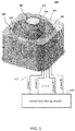
- FIG. 3 illustrates an exemplary design configuration of the positioners, which are placed on the first body of the preferred embodiment of the present invention as shown in FIG. 1 ,
- FIG. 4 shows another exemplary design configuration of the electromagnetic driving signal phases arrangement, being a hexagonal array pattern
- FIG. 5 illustrates a perspective view of another preferred embodiment of the present invention as a three-dimensional spherical motor
- FIGS. 6A and 6B illustrate front and rear perspective views of an exploded configuration of the preferred embodiment design as illustrated in FIG. 5 .
- FIG. 1 depicts an exemplary preferred embodiment of the present invention as a two-dimensional planar motion stage.
- the stage comprises a first body, the movable platform 101 , and a second body, the base 103 .
- the mating surface between the movable platform 101 and the base 103 is a plane 105 , and the movable platform 101 can move relative to the base 103 along this mating plane 105 with two degrees of translation and one degree of rotation.
- the base 103 is placed horizontally, the movable platform 101 can simply sit on the base 103 by gravity.
- Other extra geometric/physical constraints such as a ceiling component on top may be added to the system to enforce planar movement of the movable platform 101 relative to the base 103 .
- the base 103 sits in a set of stationary coordinates X S , Y S , and Z S , and the movable platform 101 has its own local coordinates: X M , Y M , and Z M .
- Z S Z M .
- a plurality of cylindrical magnets 107 are attached to the movable platform 101 .
- a plurality of electromagnets 109 are attached to the base 103 .
- the coils are arranged in a rectangular array pattern. As electrical driving current goes through each coil, attractive or repulsive electromagnetic force may be exerted on each magnet 107 .
- the forces exerted on the magnets provides force and torque, and essentially contribute to the net acceleration and angular acceleration of the base 103 to generate motions along designated dimensions.
- the total N x ⁇ N y coils are controlled by a controller 110 transmitting M driving signal phases 111 .
- the number of driving signal phases 111 may be much less than the total number of coils in the design.
- electromagnetic coils 109 in a rectangular-array configuration are controlled by a total of 4 driving phases (A, B, C, or D).
- Each electromagnetic coil 109 is denoted by a circle, and each letter inside the circle stands for the phase of the coil control signal.
- a letter with symbol prime (′) stands for reversed driving current direction, and a letter without symbol prime stands for forward driving current direction.
- the coil pitch size along ⁇ direction 201 , l S ⁇ , and the coil pitch size along ⁇ direction 203 , l S ⁇ are the same for the convenience of modeling of the control system.
- Other embodiments of the invention may also accommodate different pitch sizes along different dimensions.
- An array of 4 ⁇ 4 coils forms a unit pattern 205 for the rectangular-array configuration.
- the pattern 205 may iterate along either dimension 207 ( ⁇ circumflex over ( ⁇ ) ⁇ S and/or ⁇ circumflex over ( ⁇ ) ⁇ S ) to form a larger array of coils, still with only 4 phases in total.
- cylindrical magnets 107 may also be arranged in a rectangular array pattern. Again, for modeling convenience, we set the magnet pitch size along ⁇ direction 209 , l M ⁇ , equal to the magnet pitch size along ⁇ direction 211 , l M ⁇ .
- a preferred embodiment of hexagonal-array pattern may be utilized for arranging the coils electromagnetic coil 109 , as shown in FIG. 4 .
- the control signal arrangement also only requires 4 phases.
- a staggered array of 4 ⁇ 4 coils forms a unit pattern 213 for the hexagonal-array configuration.
- the stacking density can be increased by:
- the magnetic flux density of ith permanent magnet B i ⁇ 3 ⁇ 1 can be formulated.
- T ij r j ⁇ F ij ( Equation ⁇ ⁇ 8 )
- N c N x ⁇ N y force and torque equations like in total. Concatenating all N c equations, we can obtain the force and torque model of the actuator in the moving platform's coordinates as:
- [ F T ] [ f ⁇ ⁇ ( x 1 , y 1 , ⁇ 1 ) f ⁇ ⁇ ( x 2 , y 2 , ⁇ 2 ) ... f ⁇ ⁇ ( x N c , y N c , ⁇ N c ) f ⁇ ⁇ ( x 1 , y 1 , ⁇ 1 ) f ⁇ ⁇ ( x 2 , y 2 , ⁇ 2 ) ... f ⁇ ⁇ ( x N c , y N c , ⁇ N c ) g z ⁇ ( x 1 , y 1 , ⁇ 1 ) g z ⁇ ( x 2 , y 2 , ⁇ 2 ) ... g z ⁇ ( x N c , y N c , ⁇ N c ) ] ⁇ [ J 1 J 2 ⁇ J N c ] ⁇ ⁇ or ( Equation
- FIG. 5 depicts an exemplary preferred embodiment of the present invention as a three-dimensional spherical motor stage.
- the stage comprises a first body, the rotor platform 301 , and a second body, the stator platform 303 .
- the mating surface between the rotor platform 301 and the stator platform 303 is a spherical surface 305 , and the rotor platform 301 can move relative to the stator platform 303 along this spherical surface 305 with three degrees of rotation.
- the rotor platform 301 is positioned within an interior cavity 306 defined by the spherical surface 305 formed within the stator platform 303 such that an air gap is formed therebetween.
- additional device and/or component such as a camera module 307
- a camera module 307 may be attached to a top end 308 of the rotor 301 .
- the rotor may have a cable tube 311 (shown in FIG. 6B ) extending therethrough to allow the cables of the camera module 307 to go through a bottom end 312 of the rotor 301 , and all the way out of the stator platform 303 through a corresponding cable hole 317 extending through the stator platform 303 .
- There can be limiting mechanism such as limiting flange 315 coupled to the stator platform 303 and positioned adjacent the to avoid over rotation of the 301 , as shown in FIG. 6 .
- the coordinate transformations involved in the process would be between spherical coordinates and Cartesian coordinates (see FIG. 6 ), instead of between Cartesian coordinates in two-dimensional case.
- the present invention includes a multi-degree-of-freedom motor system 100 .
- the system 100 includes the rotor 101 , the stator 103 , and the controller 110 .
- the rotor 101 includes a rotor body and a plurality of magnetic positioners 107 coupled to the rotor body.
- the stator 103 includes a stator housing and a plurality of electromagnetic coils 109 positioned within the stator housing.
- the stator housing includes an outer surface that defines a substantially planar mating surface defined between an outer surface of the rotor body and the outer surface of the stator housing.
- the stator housing may include an outer surface that defines a spherical mating surface defined between an outer surface of the rotor body and the outer surface of the stator housing.
- the plurality of electromagnetic coils 109 are arranged in a plurality of coil groups 112 .
- Each of the coil groups 112 including a predefined number of electromagnetic coils 109 being arranged in a predefined unit pattern 205 and/or 213 .
- the controller 110 is configured to transmit control signals to each of the plurality of electromagnetic coils 109 .
- the controller 110 is configured to transmit the control signals including a number of driving signal phases 111 that is less than a total number of electromagnetic coils 109 included in the stator 103 .
- the controller 110 may be configured to transmit the control signals including a number of driving signal phases 111 that is less than half of the total number of electromagnetic coils 109 included in the stator 103 .
- the coil group 112 includes a first set 114 of electromagnet coils 109 spaced along a first direction 201 and a second set 116 of electromagnetic coils 109 spaced along a second direction 203 that is perpendicular to the first direction 201 .
- the first set 114 of electromagnetic coils 109 includes a first coil pitch size l S ⁇ is defined along the first direction 201 .
- the second set 116 of electromagnetic coils 109 includes a second coil pitch size l S ⁇ defined along the second direction 203 .
- FIG. 1 the first set 114 of electromagnetic coils 109 spaced along a first direction 201 and a second set 116 of electromagnetic coils 109 spaced along a second direction 203 that is perpendicular to the first direction 201 .
- the first set 114 of electromagnetic coils 109 includes a first coil pitch size l S ⁇ is defined along the first direction 201 .
- the second set 116 of electromagnetic coils 109 includes a second coil pitch size l S
- the first coil pitch size l S ⁇ is may be equal to the second coil pitch size l S ⁇ such that the predefined pattern includes a substantially rectangular shape.
- the second coil pitch size l S ⁇ may be less than the first coil pitch size l S ⁇ .
- the controller 110 may be configured to transmit a first driving phase, such as, for example driving phase 1 (shown in FIG. 1 ) to a pair of electromagnetic coils 109 including a first coil 118 and a second coil 120 (shown in FIG. 2 ).
- the controller 110 is configured to transmit the first driving phase 1 including a forward driving current, A, transmitted to the first coil 118 of the pair of electromagnetic coils 109 and a reverse driving current, A′, transmitted to the second coil 120 of the pair of electromagnetic coils 109 .
- the coil group 112 includes a plurality of pairs of electromagnetic coils 109 , each pair including a first coil 118 and a second coil 120 .
- Each pair of electromagnet coils 109 is arranged within the unit pattern 205 , 213 such that another electromagnet coil 109 of another pair of electromagnet coils 109 is positioned between the first and second coils 118 and 120 , as shown in FIG. 2 and FIG. 4 .
- a controller, computing device, server or computer, such as described herein, may include at least one or more processors or processing units and a system memory.
- the controller typically also includes at least some form of computer readable media.
- a computer-readable media may include one or more of a portable computer diskette, a hard disk, a random access memory (RAM) device, a read-only memory (ROM) device, an erasable programmable read-only memory (EPROM or Flash memory) device, a portable compact disc read-only memory (CDROM), an optical storage device, and a magnetic storage device.
- Computer program code for carrying out operations of the present invention may be written in any combination of one or more programming languages.
- computer readable media may include computer storage media and communication media.
- Computer storage media may include volatile and nonvolatile, removable and non-removable media implemented in any method or technology that enables storage of information, such as computer readable instructions, data structures, program modules, or other data.
- Communication media typically embody computer readable instructions, data structures, program modules, or other data in a modulated data signal such as a carrier wave or other transport mechanism and include any information delivery media.
- modulated data signal such as a carrier wave or other transport mechanism and include any information delivery media.
- a processor includes any programmable system including systems and microcontrollers, reduced instruction set circuits (RISC), application specific integrated circuits (ASIC), programmable logic circuits (PLC), and any other circuit or processor capable of executing the functions described herein.
- RISC reduced instruction set circuits
- ASIC application specific integrated circuits
- PLC programmable logic circuits
- the above examples are exemplary only, and thus are not intended to limit in any way the definition and/or meaning of the term processor.
- a database includes any collection of data including hierarchical databases, relational databases, flat file databases, object-relational databases, object oriented databases, and any other structured collection of records or data that is stored in a computer system.
- databases include, but are not limited to only including, Oracle® Database, MySQL, IBM® DBx, Microsoft® SQL Server, Sybase®, and PostgreSQL.
- any database may be used that enables the systems and methods described herein.
Abstract
Description
M phases<½(N x ×N y) Equation 1:
F=I∫dl×B (Equation 4)
where F is the net force,
dF=−Idl×B z(x,y,θ){circumflex over (Z)} S =−Jdhdrdl×B z(x,y,θ){circumflex over (Z)} S (Equation 5)
where {circumflex over (Z)}S is the unit vector in the z-direction of Cartesian coordinates of the base, and dF is the differential force in x-y plane in base coordinates. Integrating on entire coil volume for analyzing total force exerted from jth coil on ith magnet:
where the symbol ∫C denotes the line integral of the differential force. Also, since we know the position vector ri from the center of mass of the moving platform (the origin of platform's coordinates) to the ith magnet as the moment arm, the torque information can be formulated as well:
where Tij is the moment exerted on the moving platform by the interacting force between ith magnet and jth coil. For generating the force model for complete sets of coils, there will be Nc=Nx×Ny force and torque equations like in total. Concatenating all Nc equations, we can obtain the force and torque model of the actuator in the moving platform's coordinates as:
where Q is the characteristic matrix for a certain platform position and orientation relative to the base, and J is the current density vector of electric currents passing through
where W is a 4×4 (since we have 4 current signal phases) positive definite matrix in the form of
where w1, w2, w3, w4 are positive weightings determined by coils' resistances. Using state-of-the-art techniques such as the minimum right-inverse solution, the control current inputs can be obtained as:
Claims (20)
Priority Applications (1)
| Application Number | Priority Date | Filing Date | Title |
|---|---|---|---|
| US16/078,580 US10601296B2 (en) | 2016-02-26 | 2017-02-21 | Multi-degree-of-freedom motor design with reduced number of electromagnetic control phases |
Applications Claiming Priority (3)
| Application Number | Priority Date | Filing Date | Title |
|---|---|---|---|
| US201662300384P | 2016-02-26 | 2016-02-26 | |
| PCT/IB2017/050984 WO2017145051A1 (en) | 2016-02-26 | 2017-02-21 | Multi-degree-of-freedom motor design with reduced number of electromagnetic control phases |
| US16/078,580 US10601296B2 (en) | 2016-02-26 | 2017-02-21 | Multi-degree-of-freedom motor design with reduced number of electromagnetic control phases |
Publications (2)
| Publication Number | Publication Date |
|---|---|
| US20190068041A1 US20190068041A1 (en) | 2019-02-28 |
| US10601296B2 true US10601296B2 (en) | 2020-03-24 |
Family
ID=59684827
Family Applications (1)
| Application Number | Title | Priority Date | Filing Date |
|---|---|---|---|
| US16/078,580 Active US10601296B2 (en) | 2016-02-26 | 2017-02-21 | Multi-degree-of-freedom motor design with reduced number of electromagnetic control phases |
Country Status (3)
| Country | Link |
|---|---|
| US (1) | US10601296B2 (en) |
| CN (1) | CN108886331B (en) |
| WO (1) | WO2017145051A1 (en) |
Families Citing this family (4)
| Publication number | Priority date | Publication date | Assignee | Title |
|---|---|---|---|---|
| US10374483B1 (en) | 2018-07-16 | 2019-08-06 | Honeywell International Inc. | Three-axis gimbal assembly with a spherical motor |
| US11081931B2 (en) * | 2018-11-06 | 2021-08-03 | Alluvionic, Inc. | Rotating energy storage apparatus and method of imparting rotational motion of a vessel containing the same |
| ES2890431T3 (en) * | 2018-11-23 | 2022-01-19 | Tetra Laval Holdings & Finance | Capping apparatus for a production system for packaged food products |
| CN110888360A (en) * | 2019-11-26 | 2020-03-17 | 天津大学 | Magnetic fluid liquid drop motion control system based on visual servo |
Citations (14)
| Publication number | Priority date | Publication date | Assignee | Title |
|---|---|---|---|---|
| US5798590A (en) * | 1995-12-15 | 1998-08-25 | Mitsubishi Jukogyo Kabushiki Kaisha | Multi-degree-freedom electric motor |
| US6374049B1 (en) * | 1999-05-17 | 2002-04-16 | Canon Kabushiki Kaisha | Vibration prevention apparatus |
| US20030178901A1 (en) * | 2002-03-25 | 2003-09-25 | Clarity, Llc | Electromagnetic positioning |
| JP2006033978A (en) | 2004-07-14 | 2006-02-02 | Institute Of National Colleges Of Technology Japan | Spherical motor and actuator |
| US20090161240A1 (en) * | 2007-12-25 | 2009-06-25 | Hon Hai Precision Industry Co., Ltd. | Rotatable camera module |
| CN101777851A (en) | 2010-03-17 | 2010-07-14 | 天津大学 | Three degree of freedom spherical motor with multiple physical field mixing driving |
| US20110097062A1 (en) * | 2008-04-30 | 2011-04-28 | Nidec Sankyo Corporation | Optical unit with shake correcting function |
| CN102075042A (en) | 2011-02-28 | 2011-05-25 | 北京航空航天大学 | Ball type motor with three-dimensional topology magnetic pole distribution structure |
| CN202160025U (en) | 2011-07-29 | 2012-03-07 | 上海理工大学 | Multi-freedom degree spherical motor |
| JP2012105395A (en) | 2010-11-08 | 2012-05-31 | Katsuhiro Hirata | Electromagnetic actuator of high flexibility |
| US8991527B2 (en) * | 2010-12-21 | 2015-03-31 | Stmicroelectronics S.R.L. | Rolling means of a moving device and related moving device |
| CN104836408A (en) | 2015-03-24 | 2015-08-12 | 北京机械设备研究所 | Six degrees of freedom permanent magnet synchronous magnetic suspension spherical motor |
| US9178393B2 (en) * | 2010-08-04 | 2015-11-03 | National Institute Of Advanced Industrial Science And Technology | Multiple pole spherical stepping motor and multiple pole spherical AC servo motor |
| US20160223780A1 (en) * | 2015-02-04 | 2016-08-04 | Samsung Electronics Co., Ltd. | Lens driving module |
Family Cites Families (2)
| Publication number | Priority date | Publication date | Assignee | Title |
|---|---|---|---|---|
| CN100520471C (en) * | 2006-08-01 | 2009-07-29 | 扬明光学股份有限公司 | Lens module |
| CN102412772B (en) * | 2011-11-28 | 2012-10-10 | 苏州普思自动化科技有限公司 | Self-adaptive adjusting method for control parameters of motor magnetic suspension start |
-
2017
- 2017-02-21 WO PCT/IB2017/050984 patent/WO2017145051A1/en active Application Filing
- 2017-02-21 US US16/078,580 patent/US10601296B2/en active Active
- 2017-02-21 CN CN201780013418.8A patent/CN108886331B/en active Active
Patent Citations (14)
| Publication number | Priority date | Publication date | Assignee | Title |
|---|---|---|---|---|
| US5798590A (en) * | 1995-12-15 | 1998-08-25 | Mitsubishi Jukogyo Kabushiki Kaisha | Multi-degree-freedom electric motor |
| US6374049B1 (en) * | 1999-05-17 | 2002-04-16 | Canon Kabushiki Kaisha | Vibration prevention apparatus |
| US20030178901A1 (en) * | 2002-03-25 | 2003-09-25 | Clarity, Llc | Electromagnetic positioning |
| JP2006033978A (en) | 2004-07-14 | 2006-02-02 | Institute Of National Colleges Of Technology Japan | Spherical motor and actuator |
| US20090161240A1 (en) * | 2007-12-25 | 2009-06-25 | Hon Hai Precision Industry Co., Ltd. | Rotatable camera module |
| US20110097062A1 (en) * | 2008-04-30 | 2011-04-28 | Nidec Sankyo Corporation | Optical unit with shake correcting function |
| CN101777851A (en) | 2010-03-17 | 2010-07-14 | 天津大学 | Three degree of freedom spherical motor with multiple physical field mixing driving |
| US9178393B2 (en) * | 2010-08-04 | 2015-11-03 | National Institute Of Advanced Industrial Science And Technology | Multiple pole spherical stepping motor and multiple pole spherical AC servo motor |
| JP2012105395A (en) | 2010-11-08 | 2012-05-31 | Katsuhiro Hirata | Electromagnetic actuator of high flexibility |
| US8991527B2 (en) * | 2010-12-21 | 2015-03-31 | Stmicroelectronics S.R.L. | Rolling means of a moving device and related moving device |
| CN102075042A (en) | 2011-02-28 | 2011-05-25 | 北京航空航天大学 | Ball type motor with three-dimensional topology magnetic pole distribution structure |
| CN202160025U (en) | 2011-07-29 | 2012-03-07 | 上海理工大学 | Multi-freedom degree spherical motor |
| US20160223780A1 (en) * | 2015-02-04 | 2016-08-04 | Samsung Electronics Co., Ltd. | Lens driving module |
| CN104836408A (en) | 2015-03-24 | 2015-08-12 | 北京机械设备研究所 | Six degrees of freedom permanent magnet synchronous magnetic suspension spherical motor |
Non-Patent Citations (2)
| Title |
|---|
| International Search Report (PCT/IB2017/050984); dated Jun. 16, 2017. |
| Written Opinion of the International Searching Authority (PCT/IB2017/050984); dated Jun. 16, 2017. |
Also Published As
| Publication number | Publication date |
|---|---|
| WO2017145051A1 (en) | 2017-08-31 |
| CN108886331A (en) | 2018-11-23 |
| CN108886331B (en) | 2020-05-19 |
| US20190068041A1 (en) | 2019-02-28 |
Similar Documents
| Publication | Publication Date | Title |
|---|---|---|
| US10601296B2 (en) | Multi-degree-of-freedom motor design with reduced number of electromagnetic control phases | |
| Zhao et al. | Robotic assembly of haptic proxy objects for tangible interaction and virtual reality | |
| Kantaros et al. | Control of magnetic microrobot teams for temporal micromanipulation tasks | |
| CN108155770B (en) | Control system and method of three-degree-of-freedom electromagnetic machine | |
| US9373443B2 (en) | Electromagnetic coil system for driving control of micro-robot | |
| CN109623780B (en) | Camera robot for shooting multi-view continuum and using method thereof | |
| KR101792390B1 (en) | Precise spatial mover | |
| Petruska et al. | Remote manipulation with a stationary computer-controlled magnetic dipole source | |
| EP3881115B1 (en) | Actuator assembly | |
| KR20150071014A (en) | Parallel kinematic mechanism and bearings and actuators thereof | |
| US20200274435A1 (en) | Multi-degree-of-freedom electromagnetic machine | |
| EP3269650A1 (en) | Spin and tilt control of a multi-degree of freedom electromagnetic machine | |
| Zhu et al. | Flexure-based magnetically levitated dual-stage system for high-bandwidth positioning | |
| Alasli et al. | Electromagnet design for untethered actuation system mounted on robotic manipulator | |
| JP2021529568A (en) | Magnetic field generator | |
| Lloyd et al. | Magnetic soft continuum robots with braided reinforcement | |
| US7940150B2 (en) | Six-degree-of-freedom precision positioning system | |
| Begey et al. | A manipulability criterion for magnetic actuation of miniature swimmers with flexible flagellum | |
| Bai et al. | Permanent Magnet Spherical Motors | |
| CN109717821B (en) | System and method for driving micro-magnetic device by multiple rotary permanent magnets | |
| CN107612253B (en) | Input amplitude modulation control for multi-degree-of-freedom electromagnetic machine | |
| Pittiglio et al. | Closed loop static control of multi-magnet soft continuum robots | |
| Souza et al. | Design and control of a three-coil permanent magnet spherical motor | |
| Pei | Methodology of design and analysis of variable-reluctance spherical motors | |
| Ghanbari et al. | Nonlinear Modeling Application to Micro-/Nanorobotics |
Legal Events
| Date | Code | Title | Description |
|---|---|---|---|
| FEPP | Fee payment procedure |
Free format text: ENTITY STATUS SET TO UNDISCOUNTED (ORIGINAL EVENT CODE: BIG.); ENTITY STATUS OF PATENT OWNER: SMALL ENTITY |
|
| FEPP | Fee payment procedure |
Free format text: ENTITY STATUS SET TO SMALL (ORIGINAL EVENT CODE: SMAL); ENTITY STATUS OF PATENT OWNER: SMALL ENTITY |
|
| STPP | Information on status: patent application and granting procedure in general |
Free format text: NON FINAL ACTION MAILED |
|
| STPP | Information on status: patent application and granting procedure in general |
Free format text: FINAL REJECTION MAILED |
|
| STPP | Information on status: patent application and granting procedure in general |
Free format text: RESPONSE AFTER FINAL ACTION FORWARDED TO EXAMINER |
|
| STPP | Information on status: patent application and granting procedure in general |
Free format text: ADVISORY ACTION MAILED |
|
| STPP | Information on status: patent application and granting procedure in general |
Free format text: DOCKETED NEW CASE - READY FOR EXAMINATION |
|
| STPP | Information on status: patent application and granting procedure in general |
Free format text: DOCKETED NEW CASE - READY FOR EXAMINATION |
|
| AS | Assignment |
Owner name: HANGZHOU ZERO ZERO TECHNOLOGY CO., LTD., CHINA Free format text: ASSIGNMENT OF ASSIGNORS INTEREST;ASSIGNORS:ZHANG, TONG;WANG, MENGQIU;SUN, WEI;AND OTHERS;REEL/FRAME:050826/0138 Effective date: 20190505 Owner name: HANGZHOU ZERO ZERO TECHNOLOGY CO., LTD., CHINA Free format text: ASSIGNMENT OF ASSIGNORS INTEREST;ASSIGNOR:BEIJING ZERO ZERO INFINITY TECHNOLOGY CO., LTD;REEL/FRAME:050826/0556 Effective date: 20180815 Owner name: BEIJING ZERO ZERO INFINITY TECHNOLOGY CO., LTD, CH Free format text: ASSIGNMENT OF ASSIGNORS INTEREST;ASSIGNOR:LI, QICHENG;REEL/FRAME:050826/0365 Effective date: 20160226 Owner name: BEIJING ZERO ZERO INFINITY TECHNOLOGY CO., LTD, CHINA Free format text: ASSIGNMENT OF ASSIGNORS INTEREST;ASSIGNOR:LI, QICHENG;REEL/FRAME:050826/0365 Effective date: 20160226 |
|
| STPP | Information on status: patent application and granting procedure in general |
Free format text: NOTICE OF ALLOWANCE MAILED -- APPLICATION RECEIVED IN OFFICE OF PUBLICATIONS |
|
| STPP | Information on status: patent application and granting procedure in general |
Free format text: PUBLICATIONS -- ISSUE FEE PAYMENT VERIFIED |
|
| STCF | Information on status: patent grant |
Free format text: PATENTED CASE |
|
| MAFP | Maintenance fee payment |
Free format text: PAYMENT OF MAINTENANCE FEE, 4TH YR, SMALL ENTITY (ORIGINAL EVENT CODE: M2551); ENTITY STATUS OF PATENT OWNER: SMALL ENTITY Year of fee payment: 4 |