US10601168B2 - Plug connection kit, installation kit, and electrical installation - Google Patents
Plug connection kit, installation kit, and electrical installation Download PDFInfo
- Publication number
- US10601168B2 US10601168B2 US16/125,867 US201816125867A US10601168B2 US 10601168 B2 US10601168 B2 US 10601168B2 US 201816125867 A US201816125867 A US 201816125867A US 10601168 B2 US10601168 B2 US 10601168B2
- Authority
- US
- United States
- Prior art keywords
- plug
- housing
- connection kit
- plug connection
- socket
- Prior art date
- Legal status (The legal status is an assumption and is not a legal conclusion. Google has not performed a legal analysis and makes no representation as to the accuracy of the status listed.)
- Active
Links
Images


Classifications
-
- H—ELECTRICITY
- H01—ELECTRIC ELEMENTS
- H01R—ELECTRICALLY-CONDUCTIVE CONNECTIONS; STRUCTURAL ASSOCIATIONS OF A PLURALITY OF MUTUALLY-INSULATED ELECTRICAL CONNECTING ELEMENTS; COUPLING DEVICES; CURRENT COLLECTORS
- H01R13/00—Details of coupling devices of the kinds covered by groups H01R12/70 or H01R24/00 - H01R33/00
- H01R13/46—Bases; Cases
- H01R13/52—Dustproof, splashproof, drip-proof, waterproof, or flameproof cases
- H01R13/5219—Sealing means between coupling parts, e.g. interfacial seal
-
- H—ELECTRICITY
- H01—ELECTRIC ELEMENTS
- H01R—ELECTRICALLY-CONDUCTIVE CONNECTIONS; STRUCTURAL ASSOCIATIONS OF A PLURALITY OF MUTUALLY-INSULATED ELECTRICAL CONNECTING ELEMENTS; COUPLING DEVICES; CURRENT COLLECTORS
- H01R13/00—Details of coupling devices of the kinds covered by groups H01R12/70 or H01R24/00 - H01R33/00
- H01R13/46—Bases; Cases
- H01R13/502—Bases; Cases composed of different pieces
- H01R13/506—Bases; Cases composed of different pieces assembled by snap action of the parts
-
- H—ELECTRICITY
- H01—ELECTRIC ELEMENTS
- H01R—ELECTRICALLY-CONDUCTIVE CONNECTIONS; STRUCTURAL ASSOCIATIONS OF A PLURALITY OF MUTUALLY-INSULATED ELECTRICAL CONNECTING ELEMENTS; COUPLING DEVICES; CURRENT COLLECTORS
- H01R13/00—Details of coupling devices of the kinds covered by groups H01R12/70 or H01R24/00 - H01R33/00
- H01R13/46—Bases; Cases
- H01R13/52—Dustproof, splashproof, drip-proof, waterproof, or flameproof cases
- H01R13/5213—Covers
-
- H—ELECTRICITY
- H01—ELECTRIC ELEMENTS
- H01R—ELECTRICALLY-CONDUCTIVE CONNECTIONS; STRUCTURAL ASSOCIATIONS OF A PLURALITY OF MUTUALLY-INSULATED ELECTRICAL CONNECTING ELEMENTS; COUPLING DEVICES; CURRENT COLLECTORS
- H01R13/00—Details of coupling devices of the kinds covered by groups H01R12/70 or H01R24/00 - H01R33/00
- H01R13/58—Means for relieving strain on wire connection, e.g. cord grip, for avoiding loosening of connections between wires and terminals within a coupling device terminating a cable
- H01R13/5845—Means for relieving strain on wire connection, e.g. cord grip, for avoiding loosening of connections between wires and terminals within a coupling device terminating a cable the strain relief being achieved by molding parts around cable and connections
-
- H—ELECTRICITY
- H01—ELECTRIC ELEMENTS
- H01R—ELECTRICALLY-CONDUCTIVE CONNECTIONS; STRUCTURAL ASSOCIATIONS OF A PLURALITY OF MUTUALLY-INSULATED ELECTRICAL CONNECTING ELEMENTS; COUPLING DEVICES; CURRENT COLLECTORS
- H01R13/00—Details of coupling devices of the kinds covered by groups H01R12/70 or H01R24/00 - H01R33/00
- H01R13/66—Structural association with built-in electrical component
- H01R13/68—Structural association with built-in electrical component with built-in fuse
- H01R13/684—Structural association with built-in electrical component with built-in fuse the fuse being removable
-
- H—ELECTRICITY
- H02—GENERATION; CONVERSION OR DISTRIBUTION OF ELECTRIC POWER
- H02G—INSTALLATION OF ELECTRIC CABLES OR LINES, OR OF COMBINED OPTICAL AND ELECTRIC CABLES OR LINES
- H02G3/00—Installations of electric cables or lines or protective tubing therefor in or on buildings, equivalent structures or vehicles
- H02G3/02—Details
- H02G3/08—Distribution boxes; Connection or junction boxes
- H02G3/088—Dustproof, splashproof, drip-proof, waterproof, or flameproof casings or inlets
-
- H—ELECTRICITY
- H01—ELECTRIC ELEMENTS
- H01R—ELECTRICALLY-CONDUCTIVE CONNECTIONS; STRUCTURAL ASSOCIATIONS OF A PLURALITY OF MUTUALLY-INSULATED ELECTRICAL CONNECTING ELEMENTS; COUPLING DEVICES; CURRENT COLLECTORS
- H01R13/00—Details of coupling devices of the kinds covered by groups H01R12/70 or H01R24/00 - H01R33/00
- H01R13/66—Structural association with built-in electrical component
- H01R13/68—Structural association with built-in electrical component with built-in fuse
- H01R13/684—Structural association with built-in electrical component with built-in fuse the fuse being removable
- H01R13/688—Structural association with built-in electrical component with built-in fuse the fuse being removable with housing part adapted for accessing the fuse
-
- H—ELECTRICITY
- H01—ELECTRIC ELEMENTS
- H01R—ELECTRICALLY-CONDUCTIVE CONNECTIONS; STRUCTURAL ASSOCIATIONS OF A PLURALITY OF MUTUALLY-INSULATED ELECTRICAL CONNECTING ELEMENTS; COUPLING DEVICES; CURRENT COLLECTORS
- H01R31/00—Coupling parts supported only by co-operation with counterpart
- H01R31/06—Intermediate parts for linking two coupling parts, e.g. adapter
- H01R31/065—Intermediate parts for linking two coupling parts, e.g. adapter with built-in electric apparatus
-
- H—ELECTRICITY
- H02—GENERATION; CONVERSION OR DISTRIBUTION OF ELECTRIC POWER
- H02G—INSTALLATION OF ELECTRIC CABLES OR LINES, OR OF COMBINED OPTICAL AND ELECTRIC CABLES OR LINES
- H02G15/00—Cable fittings
- H02G15/013—Sealing means for cable inlets
-
- H—ELECTRICITY
- H02—GENERATION; CONVERSION OR DISTRIBUTION OF ELECTRIC POWER
- H02G—INSTALLATION OF ELECTRIC CABLES OR LINES, OR OF COMBINED OPTICAL AND ELECTRIC CABLES OR LINES
- H02G15/00—Cable fittings
- H02G15/08—Cable junctions
- H02G15/10—Cable junctions protected by boxes, e.g. by distribution, connection or junction boxes
- H02G15/115—Boxes split perpendicularly to main cable direction
Definitions
- the invention relates to a plug connection kit for connecting two cables, which is protected from penetration of water or dust, an installation kit, and an electrical installation having this plug connection kit.
- EP 1 150 392 A1 relates to an electrical connection for high-pressure environments, in which cable contacts are situated within a high pressure-resistant housing.
- a first aspect of the invention relates to a plug connection kit for connecting a branch line to a through line, comprising a plug housing having male contact inserts, a socket housing having female contact inserts, and at least two flexible cable ends, wherein one flexible cable end is molded onto the plug housing and one flexible cable end is molded onto the socket housing.
- the female and male contact inserts are each fixedly connected to cable cores in the flexible cable ends, wherein the plug housing and the socket housing are each manufactured by casting plastic onto a base body with the contact inserts inserted and flexible cable ends connected thereto, thus forming a solid one-piece plug and a solid one-piece socket.
- the female and male contact inserts are electrically connectable to one another in a contact area between the plug housing and the socket housing.
- the plug connection kit also includes a sealing sleeve that encases the plug housing, the socket housing, and the contact area between the two housings in order to protect the plug connection kit from penetration of water and/or dust.
- Another aspect relates to an installation kit having at least one flat cable, at least one plug connection kit according to the first aspect, and at least one branch line.
- a further aspect relates to an electrical installation that includes a through line designed as a flat cable, at least one plug connection kit according to the first aspect, and at least one branch line that is connected to the flat cable by a plug connection kit in each case.
- a first aspect of the invention relates to a plug connection kit for connecting a branch line to a through line.
- the through line may be designed as a flat cable
- the branch line may be designed as a round cable.
- Round cables are cables whose cores generally extend twisted in the longitudinal direction of the cable. For flat cables, the cores extend essentially in parallel over the entire length of the cable.
- the plug connection kit includes a plug housing that encloses male contact inserts.
- the male contact inserts are designed, for example, as plastic molded parts with contact tips that exit in the plug-in the direction, wherein the typically metallic surface of the contact tips may have a circular, pointed, flat, tapering, or angular design.
- the plug connection kit also includes a socket housing that encloses female contact inserts.
- the female contact inserts are designed, for example, as plastic molded parts with a cavity for accommodating the contact tips.
- the cavity has conductive elements, for example, for establishing electrical contact between the female and male contact inserts.
- the female and male contact inserts are thus electrically connectable in a contact area between the plug housing and the socket housing.
- the plug connection kit includes at least two flexible cable ends; these flexible cable ends are typically provided at the current input- and current output-side ends of the plug connection kit.
- One flexible cable end is molded onto the plug housing, and one flexible cable end is molded onto the socket housing, i.e., cast onto the plug housing and the socket housing by means of an injection molding process.
- the flexible cable end is, for example, connected to a round cable core on the plug housing side, and on the socket housing side may be connected either to a round cable or to a branch line socket that contacts a through line. Cable cores, which as a result of the casting onto the plug housing and socket housing are at least partially enclosed by the flexible material, extend through the completely filled flexible cable end.
- the female and male contact inserts are each fixedly connected to cable cores in the flexible cable ends by ultrasonic welding, for example.
- An elastic material for example, is used for the casting in order to make the cable ends flexible.
- This elastic material may also be a plastic with elastic properties. Due to the flexibility of the cable ends, the plug connection kit is bendable in the area of its ends, and therefore may also be used for nonlinear connections of two cables, for example for a contact for which, although a through line is contacted by a branch socket perpendicular to the extension direction of the through line, the branch line thus supplied is not intended to be led away perpendicularly from the through line.
- the plug housing and the socket housing are each manufactured by casting plastic onto a base body with the inserted contact inserts and flexible cable ends connected thereto, thus forming a solid one-piece plug or a solid one-piece socket.
- the plug housing includes a plug housing base body, and the socket housing includes a socket housing base body.
- the plug housing and the socket housing themselves are each manufactured by injection molding, for example; the interior of the housing is also completely filled by means of injection molding, for example.
- the male and female contact inserts are filled into the respective housing in the area of the plug housing or the socket housing.
- the plug connection kit includes a sealing sleeve that encases the plug housing, the socket housing, and the contact area between the two housings.
- the sealing sleeve provides the entire plug connection kit with at least class IP65, ideally with class IP68, protection from penetration of dust and water.
- the sealing sleeve provides additional contact protection in particular for the electrical contact points of the plug connection kit in order to make handling safer, also during installation.
- the sealing sleeve is made of hard plastic or other plastics, for example.
- the material from which the plug housing and the socket housing are cast includes at least one plastic, and the material that is molded onto this housing to form the flexible cable ends includes at least one elastomer.
- the cast-on portion of the socket housing and of the plug housing is made, for example, from a polyolefin, such as high-density polyethylene (PE-HD), to make the plug and socket mechanically stable and to provide them with seal-tightness against water or dust.
- PE-HD high-density polyethylene
- Polyolefin plastic or polyethylene plastic is cast onto the base body, which may likewise be made of this material.
- the base body is likewise cast with these same plastics, i.e., filled with injection molding material.
- the at least one elastomer from which the flexible cable ends are cast is, for example, a vulcanized material made of natural rubber or silicone rubber.
- the plug housing or socket housing together with the cast-on flexible cable ends forms the solid one-piece plug or the solid one-piece socket, respectively.
- Solid refers to the fact that the plug or the socket has no internal cavities due to the casting.
- a seal is mounted in each case on the plug housing and the socket housing in order to protect the contact area from penetration of water or dust.
- the plug housing or the socket housing, respectively, together with the seal is inserted into the sealing sleeve.
- the inlet and outlet areas of the sealing sleeve are thus also protected from penetration of water or dust when the plug housing and the socket housing are inserted into the respective openings in the sealing sleeve. Otherwise, water or dust could penetrate into the sealing sleeve through a space possibly present between the sealing sleeve and the inserted plug housing or socket housing, and could thus also penetrate in the direction of the contact area of the plug connection kit.
- this contact area is the area in which the male and female contact inserts are plugged together in order to close the electrical contact between the socket housing and the plug housing.
- the seal is a sealing ring
- the plug housing and the socket housing each have a groove on their outer side for accommodating the sealing ring. Inserting the locking rings into the groove ensures that the sealing rings remain at their intended position, even when the plug housing or socket housing is pushed into the sealing sleeve.
- the spacing of the groove from the side of the socket housing or of the plug housing facing the sealing sleeve is such that, after the plug housing and the socket housing are pushed into the sealing sleeve up to the stop 82 ( FIG. 8 ), the sealing ring comes to rest inside the sealing sleeve and seals off the space between the sealing sleeve and the solid one-piece plug or solid one-piece socket.
- the sealing sleeve at its inner side is equipped with a sealing element in each case in the inlet area and outlet area of the sealing sleeve.
- the sealing elements then also rest inside the sealing sleeve, and likewise seal a space between the plug housing/socket housing and the sealing sleeve when the housings are inserted into the sealing sleeve.
- the plug housing and the socket housing do not have to be fitted with a sealing element, but instead are inserted into a sealing sleeve that is already provided with sealing elements at its inlet and outlet.
- the sealing element inserted into the sealing sleeve is a sealing ring, and the sealing sleeve has a groove in its inlet and outlet areas for accommodating the sealing ring.
- the sealing sleeve has a lock with which the sealing sleeve may be fixed to the socket housing or the plug housing or to both. This ensures that the sealing sleeve can no longer slip in its position, at least in one direction, after a plug-in connection is established between the plug housing or the male contact inserts situated therein and the socket housing or the female contact inserts situated therein.
- the contact area of the plug-in connector is not released in a specified direction, even when acted on by tensile force. This is used on the one hand to protect from penetration of water or dust, and on the other hand is used for safety, since the sealing sleeve cannot be detached due to improper handling and expose the contact area; rather, it can be pulled off only after the lock is intentionally released.
- the lock is designed as a snap-action system that is mounted on one end of the sealing sleeve, and that can snap onto a bracket on the plug housing or on the socket housing.
- the elastomer or the elastic plastic that is injected onto the housings to form the molded-on cable ends may partially or completely enclose the socket housing or the plug housing.
- no elastomer is applied at the locations where the above-mentioned bracket(s) is/are provided for fastening the sealing sleeve to at least one of the housings, so that the snap-action system can snap into the brackets.
- the snap-action system may be implemented by snap inserts made of plastic, which in the pressed-together state are inserted into the brackets and then re-expand to fix the inserts in the bracket.
- the male and female contact inserts are made of metal and are fixedly connected to the cable cores by ultrasonic welding.
- the female and male contact inserts may snap into a contact position in the plug housing or the socket housing by means of a snap-action system that is provided in the plug housing or socket housing.
- the male and female contact inserts are in a contact position when they protrude far enough from the plug housing or the socket housing that, when the plug housing and the socket housing are plugged together (inside the sealing sleeve), i.e., the electrical contact is established, the male contact insert penetrates up to a stop in the female contact insert.
- the plug connection kit includes a fuse block, placed between the socket housing and the plug housing, having at least one fuse holder and at least one fuse insert for at least one fuse-protected core, and electrical contact points for nonfuse-protected cores.
- the fuse block essentially forms the contact area in which the female contact inserts are connected to the male contact inserts.
- the fuse block may be designed as a plastic molded part that includes fuse holders for plug-in fuses for fuse-protected cores, for example, into which the contact inserts may be inserted, and conducting elements at which the contact inserts of the nonfuse-protected cores may be connected to one another.
- a fuse holder for example including two securing plates for contacting the fuses, and a fuse insert, designed as a plug-in fuse, may be provided in each case for all contact inserts that are connected to phase-conducting cores of the line to be connected, while for contact inserts that are connected to neutral conductors or protective conductors, conducting elements are provided which accommodate the contact inserts at their respective ends.
- a female contact insert that is connected to a fuse-protected core may instead be designed with a cavity, described above, for accommodating the male contact insert at its tip, with a securing plate for contacting a plug-in fuse.
- a male contact insert that is connected to a fuse-protected core may be designed as a contact pin which is provided for contacting a securing plate, and which when plugged in contacts a securing plate that is already present in the fuse block.
- the fuse holder may be uninstalled only on the side of the socket housing in order to replace the fuse.
- the fuse holder is uninstalled, for example, after pulling out the socket housing together with the female contact inserts, as the result of which, in designs in which the female contact insert itself has a securing plate, the fuse inserts are already exposed for replacement.
- the conducting elements in the fuse block have securing plates for accommodating the fuse, and the female contact element is connected to such conducting elements, after pulling off the socket housing it is also necessary to pull off the portion of the conducting elements on the socket side prior to replacement of the fuse.
- the sealing sleeve has a stop for the plug housing, so that the fuse replacement can be carried out only in the absence of current.
- the plug housing cannot be pulled out as well or slide down, as the result of which the electrical connection between the contact inserts of the plug housing and the fuse holder in the fuse block is separated when the fuse block is pulled out. This ensures that no current flows through the fuse inserts during replacement of the fuse.
- Another aspect relates to an installation kit having at least one flat cable, at least one plug connection kit according to the first aspect, and at least one branch line.
- a further aspect relates to an electrical installation that includes a through line designed as a flat cable, at least one plug connection kit according to the first aspect, and at least one branch line that is connected to the flat cable by a plug connection kit in each case.
- FIG. 1 schematically shows a connection of a round cable to a flat cable via a plug-in connection having a flexible cable end
- FIG. 2 shows a schematic rear view of a plug housing having a sealing ring groove, without contact inserts inserted
- FIG. 3 shows an exploded view of a plug-in connection together with a sealing sleeve and female and male contact inserts, in which a plug housing and a socket housing each bear a sealing ring in a groove,
- FIG. 4 shows a schematic illustration of a detail of the plug-in connection from FIG. 3 in the assembled state
- FIG. 5 shows an exploded view of a sealing sleeve with a sealing ring inserted into a groove on the inlet side and outlet side, with sealing plugs on both sides for fixing this sealing ring,
- FIG. 6 shows an exploded view of a detail of the plug-in connection, with a sealing sleeve having an interior sealing ring and sealing plugs connected on both sides,
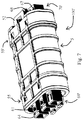
- FIG. 7 shows the detail of the plug-in connection from FIG. 7 [sic; 6 ] in the assembled state
- FIG. 8 shows a schematic sectional view of a detail of the plug-in connection with a fuse block inserted therein for providing fuse protection to the connection of two phase conductors
- FIG. 9 shows a schematic top view of a detail of the plug-in connection according to FIGS. 3 through 8 , with flexible cable ends molded onto both sides.
- the plug connection kit according to FIG. 1 connects a multicore flat cable 7 to a multicore round cable 1 .
- the cores of the flat cable are tapped by a connection device 6 , and the current can flow through conductive elements within the connection device 6 and into a socket connected to the connection device.
- the socket has a socket housing 4 which is part of the described plug connection kit 100 .
- the socket is equipped with female contact inserts 40 (see FIG. 3 ) which are enclosed by the socket housing 4 .
- Male contact inserts 30 (see FIG. 3 ) of a plug are plugged into the female contact inserts 40 of the socket housing 4 plug at the connection point between the plug and the socket. This location at which the male and female contact inserts 30 , 40 engage with one another thus forms a contact area 80 .
- the male contact inserts 30 are enclosed by a plug housing 3 .
- the socket housing 4 and the plug housing 3 are embedded in a sealing sleeve 5 in order to protect the contact area 80 from penetration of water or dust.
- Associated flexible cable ends 2 , 2 ′ made of an elastomer or plastic having elastic properties are in each case molded onto the plug housing 3 and the socket housing 4 .
- the cable cores 1 ′ of the round cable 1 are guided by the flexible cable end 2 and are connected to the male contact inserts 30 of the plug housing 3 .
- the plug housing 3 together with the flexible cable end 2 forms the solid plug 500 .
- the socket housing 4 together with the flexible cable end 2 ′ forms the solid socket 600 .
- the plug housing 3 as well as the socket housing 4 are manufactured via injection molding by casting plastic onto a base body 60 (see FIG. 3 ), which should encompass the complete casting of the base body 60 . This provides additional protection from penetration of water or dust in the direction into the interior of the plug connection kit 100 .
- the plug housing and socket housing each include a base body 60 illustrated in FIG. 2 , having rectangular receptacles for the contact inserts 64 , and emerging from these receptacles 64 , has adjoining circular guide tubes 65 , only indicated in FIG. 2 , for guiding the contact tip of a male contact insert 3 .
- the receptacles 64 having a square cross section are provided with a snap-action system 2 , into which the male contact inserts 30 (not illustrated here) can snap in in a specified position.
- the base body 60 is equipped with brackets 61 which emerge from the front side at its top and bottom. These brackets 61 are provided as part of a snap-action system that is used to lock the sealing sleeve 5 (see FIG. 3 ) in a specified position on the plug housing 3 .
- the base body 60 is provided on its outer side with a groove 11 ′ to accommodate a sealing ring 9 made of rubber.
- the sealing ring 9 is intended to prevent water from flowing along the plug housing 3 and into the interior of the plug-in connection when the plug housing 3 is inserted into the sealing sleeve 5 , not illustrated in FIG. 2 .
- the overall plug connection kit 100 is illustrated in an exploded view in FIG. 3 .
- male contact inserts 30 are pushed through the rectangular receptacles 64 in the base body 60 and then fixed in a position in which they protrude with their tip from the guide tubes 65 .
- the female contact inserts 40 are guided through receptacles having a square cross section 67 , and via snap inserts, not illustrated in FIG. 3 , are fixed in a position in which their tip protrudes from the guide tubes 66 .
- the female contact inserts have a cavity in their tip in which they are able to accommodate the contact tips of the male contact inserts.
- the plug housing 3 or the socket housing 4 which encloses the male 30 contact inserts or female contact inserts 40 , respectively, is manufactured by molding the plastic onto the base body.
- the plug housing 3 as well as the socket housing 4 are provided with grooves 11 ′, 11 ′′ on the top side of their respective base body 60 or 70 , into which a sealing ring 9 , 9 ′, respectively, is inserted.
- the socket housing 4 and the plug housing 3 are pushed into the sealing sleeve 5 so that the female and male contact inserts inserted into the particular housings contact one another.
- the sealing sleeve 5 is fixed, via a snap-action system made up of a bracket 61 , to the plug housing 3 and to a clip element 51 on the side of the sealing sleeve 5 into which the plug housing is to be inserted.
- the plug connection kit 100 is illustrated in FIG. 4 in the assembled state, but without cast-on plastic.
- the single elements that protrude from the sealing sleeve 5 are the receptacles 64 , 63 , having a rectangular cross section, in the plug housing 3 or in the socket housing 4 , and the brackets 61 , 68 that emerge therefrom, wherein the clip element 51 of the sealing sleeve is snapped into the bracket 61 of the plug housing.
- FIG. 5 Another embodiment of a sealing sleeve 5 ′ is illustrated in an exploded view in FIG. 5 .
- the sealing sleeve 5 ′ in contrast to the sealing sleeve 5 shown in the preceding figures (see FIG. 3 ), has a groove 11 for accommodating a sealing ring 10 (made of rubber, for example) in its inlet or outlet areas.
- the sealing sleeve 5 ′ also includes inlet- and outlet-side sealing plugs 55 , 55 ′, which may likewise be fixed to the inlet or outlet of the sealing sleeve 5 ′ by means of respectively associated snap-in systems 56 , 56 ′.
- FIG. 6 illustrates the sealing sleeve 5 ′ with inserted sealing rings 10 (not shown in FIG. 6 ) in an exploded view, together with the other parts of a plug connection kit 100 ′.
- the female and male contact inserts 30 , 40 are identical to those shown in FIG. 3 .
- the base bodies 60 ′, 70 ′ and the plug housing 3 ′ or socket housing 4 ′ enclosing them differ from those in FIG. 3 , in that on their top side no sealing rings 9 are inserted.
- the function of these sealing rings is taken over by the sealing rings 10 placed at the inlet and outlet of the sealing sleeve 5 ′. Therefore, it is not necessary to place sealing rings 9 , 9 ′ on the housings.
- the plug connection kit 100 ′ is shown in the assembled state, but without cast-on plastic, in FIG. 7 .
- the plug connection kit 100 ′ except for the use of the sealing sleeve 5 ′ illustrated in FIGS. 4 and 5 instead of the sealing sleeve 5 illustrated in FIG. 3 , is practically identical to the plug connection kit 100 illustrated in an exploded view in FIG. 3 .
- a fuse block 34 is provided between the plug housing 3 and the socket housing 4 .
- the fuse block 34 includes three conducting elements 35 .
- a conducting element which contacts female contact elements 40 and male contact elements 30 that are to be connected to a phase-conducting core, as a fuse socket having securing plates 37 ′ or 37 ′′ is provided in each case on the plug side and the socket side.
- a fuse insert 37 for example an overcurrent fuse, is inserted into this fuse socket that is formed by the securing plates 37 ′, 37 ′′.
- the contact tips of the male contact elements 30 which are connected to neutral conducting cores or fuse conductor cores (not live), penetrate into the conducting elements 35 without a securing plate. These conducting elements 35 at their opposite end in turn penetrate into female contact elements 40 .
- the connecting elements 35 thus form a contact area 80 between the plug housing 3 and the socket housing 4 .
- a variant of the plug-in connection is selected in which the sealing rings 9 , 9 ′ rest in grooves on the outer surface of the plug housing or of the socket housing, and are not already inserted into the sealing sleeve 5 (see FIG. 3 ).
- the sealing sleeve is equipped with clip elements 51 , 52 on both sides.
- the sealing sleeve 5 ′ may also be selected, in which the sealing rings 10 (not illustrated in FIG. 8 ) are inserted at the inlets and outlets of the sealing sleeve.
- the plug connection kit 100 illustrated in FIG. 9 whose design corresponds to that of the plug connection kit 100 according to the exploded view from FIG. 3 , having base bodies 60 , 70 with plastic that is already cast on, and which thus form a plug housing 3 or a socket housing 4 , has two flexible cable ends, namely, a flexible cable end 2 ′ on the socket side and a flexible cable end 2 on the plug side.
- the cable ends have been produced by injection molding or extrusion coating of the plug housing 3 (not visible in FIG. 9 ) or of the socket housing 4 (likewise not visible in FIG. 9 ) with an elastomer.
- sealing sleeve 5 ′ may be selected instead of the sealing sleeve 5 (see FIG. 3 ) shown in FIG. 9 .
- a plug connection kit 100 ′′ according to FIG. 8 having a fuse block between the plug housing and the socket housing, may be selected instead of the design of the plug connection kit 100 according to FIG. 3 , without a fuse block between the plug housing and the socket housing.
Abstract
Description
Claims (13)
Applications Claiming Priority (3)
| Application Number | Priority Date | Filing Date | Title |
|---|---|---|---|
| EP17190596.1 | 2017-09-12 | ||
| EP17190596 | 2017-09-12 | ||
| EP17190596.1A EP3454427B1 (en) | 2017-09-12 | 2017-09-12 | Connection kit, installation kit and electric installation |
Publications (2)
| Publication Number | Publication Date |
|---|---|
| US20190081436A1 US20190081436A1 (en) | 2019-03-14 |
| US10601168B2 true US10601168B2 (en) | 2020-03-24 |
Family
ID=59856457
Family Applications (1)
| Application Number | Title | Priority Date | Filing Date |
|---|---|---|---|
| US16/125,867 Active US10601168B2 (en) | 2017-09-12 | 2018-09-10 | Plug connection kit, installation kit, and electrical installation |
Country Status (2)
| Country | Link |
|---|---|
| US (1) | US10601168B2 (en) |
| EP (1) | EP3454427B1 (en) |
Cited By (2)
| Publication number | Priority date | Publication date | Assignee | Title |
|---|---|---|---|---|
| USD896758S1 (en) * | 2019-02-22 | 2020-09-22 | Ppc Broadband, Inc. | Connector sleeve with cutout |
| US20220329026A1 (en) * | 2019-06-19 | 2022-10-13 | Blooming International Limited | Serially-connectable device for electrical cable |
Families Citing this family (28)
| Publication number | Priority date | Publication date | Assignee | Title |
|---|---|---|---|---|
| US10907781B2 (en) | 2018-03-09 | 2021-02-02 | Blooming International Limited | LED decorative lighting assembly having two parallel conductors and an insulating portion encapsulating portions of the conductors and a space there between |
| USD894836S1 (en) * | 2018-11-20 | 2020-09-01 | Japan Aviation Electronics Industry, Limited | Connector |
| DE102019125153B4 (en) | 2019-09-18 | 2022-02-17 | Seliger Gmbh | Plug-in coupling for a lamp and connection system for an outdoor lamp |
| WO2021150763A1 (en) | 2020-01-22 | 2021-07-29 | GAF Energy LLC | Integrated photovoltaic roofing shingles, methods, systems, and kits thereof |
| USD924158S1 (en) * | 2020-02-24 | 2021-07-06 | Dsm&T Company, Inc. | Connector with locking tabs |
| US11961928B2 (en) | 2020-02-27 | 2024-04-16 | GAF Energy LLC | Photovoltaic module with light-scattering encapsulant providing shingle-mimicking appearance |
| MX2022012640A (en) | 2020-04-09 | 2023-01-11 | GAF Energy LLC | Three-dimensional laminate photovoltaic module. |
| US11217715B2 (en) | 2020-04-30 | 2022-01-04 | GAF Energy LLC | Photovoltaic module frontsheet and backsheet |
| WO2021230938A1 (en) * | 2020-05-13 | 2021-11-18 | GAF Energy LLC | Electrical cable passthrough |
| EP4162603A1 (en) | 2020-06-04 | 2023-04-12 | Gaf Energy LLC | Photovoltaic shingles and methods of installing same |
| MX2023000952A (en) | 2020-07-22 | 2023-04-19 | GAF Energy LLC | Photovoltaic modules. |
| EP4208902A1 (en) | 2020-09-03 | 2023-07-12 | Gaf Energy LLC | Building integrated photovoltaic system |
| US11545928B2 (en) | 2020-10-13 | 2023-01-03 | GAF Energy LLC | Solar roofing system |
| US11444569B2 (en) | 2020-10-14 | 2022-09-13 | GAF Energy LLC | Mounting apparatus for photovoltaic modules |
| US11454027B2 (en) | 2020-10-29 | 2022-09-27 | GAF Energy LLC | System of roofing and photovoltaic shingles and methods of installing same |
| CA3197587A1 (en) | 2020-11-12 | 2022-05-19 | Gabriela Bunea | Roofing shingles with handles |
| WO2022103841A1 (en) | 2020-11-13 | 2022-05-19 | GAF Energy LLC | Photovoltaic module systems and methods |
| US11459757B2 (en) | 2021-01-19 | 2022-10-04 | GAF Energy LLC | Watershedding features for roofing shingles |
| USD964287S1 (en) | 2021-01-19 | 2022-09-20 | Dsm&T Company, Inc. | Electrical connector with flange |
| USD998570S1 (en) | 2021-01-19 | 2023-09-12 | Dsm&T Company, Inc. | Triangular electrical connector with flange |
| US11496088B2 (en) | 2021-02-19 | 2022-11-08 | GAF Energy LLC | Photovoltaic module for a roof with continuous fiber tape |
| US11527665B2 (en) | 2021-05-06 | 2022-12-13 | GAF Energy LLC | Photovoltaic module with transparent perimeter edges |
| CA3215217A1 (en) | 2021-06-02 | 2022-12-08 | Richard Perkins | Photovoltaic module with light-scattering encapsulant providing shingle-mimicking appearance |
| WO2023287584A1 (en) | 2021-07-16 | 2023-01-19 | GAF Energy LLC | Roof material storage bracket |
| US11728759B2 (en) | 2021-09-01 | 2023-08-15 | GAF Energy LLC | Photovoltaic modules for commercial roofing |
| US11824486B2 (en) | 2022-01-20 | 2023-11-21 | GAF Energy LLC | Roofing shingles for mimicking the appearance of photovoltaic modules |
| WO2024042056A1 (en) * | 2022-08-26 | 2024-02-29 | Stäubli Electrical Connectors Ag | Housing assembly for an electrical component |
| US11811361B1 (en) | 2022-12-14 | 2023-11-07 | GAF Energy LLC | Rapid shutdown device for photovoltaic modules |
Citations (15)
| Publication number | Priority date | Publication date | Assignee | Title |
|---|---|---|---|---|
| US4545632A (en) * | 1982-11-26 | 1985-10-08 | Robert Bosch Gmbh | Modular electrical distribution connection set |
| EP1150392A1 (en) | 2000-04-28 | 2001-10-31 | Greene, Tweed Of Delaware, Inc. | Hermetic electrical connector and method of making the same |
| DE10054714A1 (en) | 2000-11-04 | 2002-05-29 | Siegfried Rebhan | Sealing cable into/onto cable leadthrough channel involves spraying an especially elastomeric sealing element, applying mold, injecting hollow volume with harder plastic material |
| US6486766B1 (en) * | 2000-03-14 | 2002-11-26 | Littlefuse, Inc. | Housing for double-ended fuse |
| US7150642B1 (en) * | 2004-06-10 | 2006-12-19 | Bakke John S | Irrigation control system |
| US7854629B1 (en) * | 2010-01-19 | 2010-12-21 | Flowserve Management Company | Power plug system for submersible pump system |
| US20110034041A1 (en) * | 2009-08-05 | 2011-02-10 | Teledyne Odi, Inc. | Electrical penetrator assembly |
| US20130137285A1 (en) * | 2010-08-17 | 2013-05-30 | Yazaki Corporation | Connector for flat cables |
| US20140213074A1 (en) * | 2013-01-31 | 2014-07-31 | Tyco Electronics Corporation | Electrical connector |
| US20150118880A1 (en) * | 2012-03-12 | 2015-04-30 | Molex Incorporated | Power connector with thermal conductivity |
| US20160036161A1 (en) * | 2013-03-15 | 2016-02-04 | Aqua Products, Inc. | Waterproof separable swivel connector |
| JP2016072049A (en) | 2014-09-30 | 2016-05-09 | 株式会社オートネットワーク技術研究所 | connector |
| US20160190742A1 (en) * | 2013-10-18 | 2016-06-30 | Woodhead Industries, Inc. | Push-lock electrical connector |
| US20170149170A1 (en) * | 2013-03-28 | 2017-05-25 | Cameron Stuart Tait | Connector plug and socket |
| US20170294737A1 (en) * | 2014-09-16 | 2017-10-12 | Fci Usa Llc | Hermetically sealed electrical connector assembly |
-
2017
- 2017-09-12 EP EP17190596.1A patent/EP3454427B1/en active Active
-
2018
- 2018-09-10 US US16/125,867 patent/US10601168B2/en active Active
Patent Citations (16)
| Publication number | Priority date | Publication date | Assignee | Title |
|---|---|---|---|---|
| US4545632A (en) * | 1982-11-26 | 1985-10-08 | Robert Bosch Gmbh | Modular electrical distribution connection set |
| US6486766B1 (en) * | 2000-03-14 | 2002-11-26 | Littlefuse, Inc. | Housing for double-ended fuse |
| EP1150392A1 (en) | 2000-04-28 | 2001-10-31 | Greene, Tweed Of Delaware, Inc. | Hermetic electrical connector and method of making the same |
| US6582251B1 (en) * | 2000-04-28 | 2003-06-24 | Greene, Tweed Of Delaware, Inc. | Hermetic electrical connector and method of making the same |
| DE10054714A1 (en) | 2000-11-04 | 2002-05-29 | Siegfried Rebhan | Sealing cable into/onto cable leadthrough channel involves spraying an especially elastomeric sealing element, applying mold, injecting hollow volume with harder plastic material |
| US7150642B1 (en) * | 2004-06-10 | 2006-12-19 | Bakke John S | Irrigation control system |
| US20110034041A1 (en) * | 2009-08-05 | 2011-02-10 | Teledyne Odi, Inc. | Electrical penetrator assembly |
| US7854629B1 (en) * | 2010-01-19 | 2010-12-21 | Flowserve Management Company | Power plug system for submersible pump system |
| US20130137285A1 (en) * | 2010-08-17 | 2013-05-30 | Yazaki Corporation | Connector for flat cables |
| US20150118880A1 (en) * | 2012-03-12 | 2015-04-30 | Molex Incorporated | Power connector with thermal conductivity |
| US20140213074A1 (en) * | 2013-01-31 | 2014-07-31 | Tyco Electronics Corporation | Electrical connector |
| US20160036161A1 (en) * | 2013-03-15 | 2016-02-04 | Aqua Products, Inc. | Waterproof separable swivel connector |
| US20170149170A1 (en) * | 2013-03-28 | 2017-05-25 | Cameron Stuart Tait | Connector plug and socket |
| US20160190742A1 (en) * | 2013-10-18 | 2016-06-30 | Woodhead Industries, Inc. | Push-lock electrical connector |
| US20170294737A1 (en) * | 2014-09-16 | 2017-10-12 | Fci Usa Llc | Hermetically sealed electrical connector assembly |
| JP2016072049A (en) | 2014-09-30 | 2016-05-09 | 株式会社オートネットワーク技術研究所 | connector |
Cited By (2)
| Publication number | Priority date | Publication date | Assignee | Title |
|---|---|---|---|---|
| USD896758S1 (en) * | 2019-02-22 | 2020-09-22 | Ppc Broadband, Inc. | Connector sleeve with cutout |
| US20220329026A1 (en) * | 2019-06-19 | 2022-10-13 | Blooming International Limited | Serially-connectable device for electrical cable |
Also Published As
| Publication number | Publication date |
|---|---|
| EP3454427B1 (en) | 2021-02-24 |
| US20190081436A1 (en) | 2019-03-14 |
| EP3454427A1 (en) | 2019-03-13 |
Similar Documents
| Publication | Publication Date | Title |
|---|---|---|
| US10601168B2 (en) | Plug connection kit, installation kit, and electrical installation | |
| US10424879B2 (en) | Hybrid plug connector | |
| JP5797283B2 (en) | High voltage connector assembly | |
| US7530843B1 (en) | Sealed electrical terminal | |
| US8888535B2 (en) | Corrosion resistant electrical assembly with connectors and multi-port junction block | |
| US9825445B2 (en) | Strain/vibration relieving cable housing device | |
| TWI528409B (en) | Inline fuse holder assembly, method of assembling together a fuse assembly and fuse holder assembly, and fuse assembly | |
| US9106066B2 (en) | Wire fixing member | |
| US7285014B2 (en) | Cord connector having a water-resistant seal | |
| US20160240957A1 (en) | Sealed electrical cable connector | |
| MX2008014090A (en) | Plug connector. | |
| US7959475B2 (en) | Cable-arraying for connectors | |
| KR20130008567A (en) | Contacts means for attaching an end of a schielded cable | |
| US9647370B2 (en) | Connector | |
| US9954307B2 (en) | Connector plug and socket having a wire clamping configuration | |
| US10103496B2 (en) | Electric connector with shield contact | |
| US9515404B2 (en) | Electrical contact plug and plug housing | |
| US6485332B1 (en) | System for reconfiguring connector cover and seal | |
| JP2018133278A (en) | Charging inlet | |
| EP3243243B1 (en) | Cable connector assembly with releasable connectors | |
| US20180294629A1 (en) | Device and method for splicing shielded wire cables | |
| JP2015204135A (en) | Waterproof structure of wiring harness with connector | |
| US9614305B2 (en) | Connector | |
| CN109273917B (en) | Waterproof connector female head and waterproof connector | |
| CN112292789B (en) | Waterproof structure of multi-core wire |
Legal Events
| Date | Code | Title | Description |
|---|---|---|---|
| FEPP | Fee payment procedure |
Free format text: ENTITY STATUS SET TO UNDISCOUNTED (ORIGINAL EVENT CODE: BIG.); ENTITY STATUS OF PATENT OWNER: LARGE ENTITY |
|
| STPP | Information on status: patent application and granting procedure in general |
Free format text: DOCKETED NEW CASE - READY FOR EXAMINATION |
|
| AS | Assignment |
Owner name: WOERTZ ENGINEERING AG, SWITZERLAND Free format text: ASSIGNMENT OF ASSIGNORS INTEREST;ASSIGNORS:ONODI, TAMAS;DREIER, ANDREAS;REEL/FRAME:048706/0056 Effective date: 20181008 |
|
| STPP | Information on status: patent application and granting procedure in general |
Free format text: NON FINAL ACTION MAILED |
|
| STPP | Information on status: patent application and granting procedure in general |
Free format text: RESPONSE TO NON-FINAL OFFICE ACTION ENTERED AND FORWARDED TO EXAMINER |
|
| STPP | Information on status: patent application and granting procedure in general |
Free format text: NOTICE OF ALLOWANCE MAILED -- APPLICATION RECEIVED IN OFFICE OF PUBLICATIONS |
|
| STPP | Information on status: patent application and granting procedure in general |
Free format text: PUBLICATIONS -- ISSUE FEE PAYMENT VERIFIED |
|
| STCF | Information on status: patent grant |
Free format text: PATENTED CASE |
|
| MAFP | Maintenance fee payment |
Free format text: PAYMENT OF MAINTENANCE FEE, 4TH YEAR, LARGE ENTITY (ORIGINAL EVENT CODE: M1551); ENTITY STATUS OF PATENT OWNER: LARGE ENTITY Year of fee payment: 4 |