TECHNICAL FIELD
The present disclosure relates to an information processing device and an information processing method.
BACKGROUND ART
Patent Literature 1 discloses a technique of assigning tag information to resource information.
CITATION LIST
Patent Literature
Patent Literature 1: JP 2007-272390A
SUMMARY OF INVENTION
Technical Problem
However, in the technique disclosed in Patent Literature 1, when tag information is assigned to object information on a social network, it is difficult to associate pieces of the tag information with each other. Therefore, the tag information is not sufficiently used.
For this reason, when tag information is assigned to object information on a social network, there is a demand for a technique capable of associating pieces of tag information with each other.
Solution to Problem
According to the present disclosure, there is provided an information processing device including a control unit configured to associate a plurality of pieces of tag information assigned to object information existing on a social network.
According to the present disclosure, there is provided an information processing method including associating a plurality of pieces of tag information assigned to object information existing on a social network.
According to the present disclosure, pieces of tag information may be able to associated with each other when the pieces of tag information are assigned to object information existing on a social network.
Advantageous Effects of Invention
As described above, according to the present disclosure, it is possible to associate the pieces of tag information with each other when the tag information is assigned to the object information on the social network. A technology according to the present disclosure may have an effect described in this specification or any other effect.
BRIEF DESCRIPTION OF DRAWINGS
FIG. 1 is a block diagram illustrating an overall configuration of an information processing system according to a first embodiment of the present disclosure.
FIG. 2 is a block diagram illustrating an example of a tag processing server and a tag management server.
FIG. 3 is a hardware configuration diagram illustrating an example of a tag processing server and a tag management server.
FIG. 4 is a block diagram illustrating an example of a user terminal.
FIG. 5 is a hardware configuration diagram illustrating an example of a user terminal.
FIG. 6 is an explanatory diagram illustrating an example of a hierarchical structure of a program (software) according to the first embodiment.
FIG. 7 is a flowchart illustrating a procedure of a process performed in an information processing system.
FIG. 8 is a flowchart illustrating a procedure of a process performed in an information processing system.
FIG. 9 is a flowchart illustrating a procedure of a process performed in an information processing system.
FIG. 10 is an explanatory diagram illustrating an example of tag relevance information.
FIG. 11 is an explanatory diagram illustrating an example of tag relevance information before a tag folder is created.
FIG. 12 is an explanatory diagram illustrating an example of tag relevance information after a tag folder is created.
FIG. 13 is an explanatory diagram illustrating an example of tag relevance information in which a browsing restriction is set.
FIG. 14 is an explanatory diagram illustrating an example of a screen displayed on a user terminal.
FIG. 15 is an explanatory diagram illustrating an example of a screen displayed on a user terminal.
FIG. 16 is an explanatory diagram illustrating an example of a screen displayed on a user terminal.
FIG. 17 is an explanatory diagram illustrating an example of a screen displayed on a user terminal.
FIG. 18 is an explanatory diagram illustrating an example of a screen displayed on a user terminal.
FIG. 19 is an explanatory diagram illustrating an example of a screen displayed on a user terminal.
FIG. 20 is an explanatory diagram illustrating an example of a screen displayed on a user terminal.
FIG. 21 is an explanatory diagram illustrating an example of a screen displayed on a user terminal.
FIG. 22 is an explanatory diagram illustrating an example of a screen displayed on a user terminal.
FIG. 23 is an explanatory diagram illustrating an example of a screen displayed on a user terminal.
FIG. 24 is an explanatory diagram illustrating an example of a screen displayed on a user terminal.
FIG. 25 is an explanatory diagram illustrating an example of a screen displayed on a user terminal.
FIG. 26 is an explanatory diagram illustrating an example of a screen displayed on a user terminal.
FIG. 27 is an explanatory diagram illustrating an example of a screen displayed on a user terminal.
FIG. 28 is an explanatory diagram illustrating an example of a screen displayed on a user terminal.
FIG. 29 is an explanatory diagram illustrating an example of a screen displayed on a user terminal.
FIG. 30 is an explanatory diagram illustrating an example of a screen displayed on a user terminal.
FIG. 31 is an explanatory diagram illustrating an example of a screen displayed on a user terminal.
FIG. 32 is an explanatory diagram illustrating an example of a screen displayed on a user terminal.
FIG. 33 is an explanatory diagram illustrating an example of a screen displayed on a user terminal.
FIG. 34 is an explanatory diagram illustrating an example of a screen displayed on a user terminal.
FIG. 35 is a block diagram illustrating an overall configuration of an information processing system according to a second embodiment of the present disclosure.
FIG. 36 is a block diagram illustrating an example of an SNS processing server and an SNS management server.
FIG. 37 is a hardware configuration diagram illustrating an example of an SNS processing server and an SNS management server.
FIG. 38 is an explanatory diagram illustrating an example of a hierarchical structure of a program (software) according to the second embodiment.
FIG. 39 is a flowchart illustrating a procedure of a process performed in an information processing system.
FIG. 40 is a flowchart illustrating a procedure of a process performed in an information processing system.
FIG. 41 is an explanatory diagram illustrating an example of personal tag relevance information.
FIG. 42 is an explanatory diagram illustrating an example of personal tag relevance information.
FIG. 43 is an explanatory diagram illustrating an example of personal tag relevance information.
FIG. 44 is an explanatory diagram illustrating an example of personal tag relevance information.
FIG. 45 is an explanatory diagram illustrating an example of the tag aggregation information.
FIG. 46 is an explanatory diagram illustrating an example of global tag relevance information.
FIG. 47 is an explanatory diagram illustrating an example of a screen displayed on a user terminal.
FIG. 48 is an explanatory diagram illustrating an example of a screen displayed on a user terminal.
FIG. 49 is an explanatory diagram illustrating an example of a screen displayed on a user terminal.
FIG. 50 is an explanatory diagram illustrating an example of a screen displayed on a user terminal.
FIG. 51 is an explanatory diagram illustrating an example of a screen displayed on a user terminal.
FIG. 52 is a block diagram illustrating a modified example of an information processing system.
FIG. 53 is an explanatory diagram illustrating an example of a screen displayed on a user terminal.
DESCRIPTION OF EMBODIMENT(S)
Hereinafter, (a) preferred embodiment(s) of the present disclosure will be described in detail with reference to the appended drawings. In this specification and the appended drawings, structural elements that have substantially the same function and structure are denoted with the same reference numerals, and repeated explanation of these structural elements is omitted.
The description will proceed in the following order.
1. First embodiment (tag relevance information is shared by a plurality of users)
1-1. Overall configuration
1-2. Configuration of tag processing server
1-3. Configuration of tag management server
1-4. Configuration of user terminal
1-5. Tag relevance information creation process
1-6. Maintenance process
1-6-1. Overview of process
1-6-2. Tag association process
1-6-3. Folder management process
1-6-4. Browsing restriction setting process
1-6-5. Recommendation process
1-7. Search process
1-8. Other processes
1-8-1. Tag creation using maintenance icon
1-8-2. Maintenance-specialized user
2. Second embodiment (setting of personal tag information and global tag information)
2-1. Overall configuration
2-2. Configuration of SNS processing server
2-3. Configuration of SNS management server
2-4. Configuration of tag processing server
2-5. Configuration of tag management server
2-6. Configuration of user terminal
2-7. Tag relevance information creation process
2-8. Maintenance process
2-9. Other processes
2-10. Modified examples
1. First Embodiment
1-1. Overall Configuration
First, an overall configuration of an information processing system 1 according to the first embodiment will be described with reference to FIG. 1. The information processing system 1 includes a tag processing server (an information processing device) 10, an SNS management server 51, a network 30, and a plurality of user terminals 40. The tag processing server 10 and the user terminals 40 are connected via the network 30. The tag processing server 10 is a server that provides a social network service (SNS) to the user terminals 40 and associates pieces of tag information with each other. In the first embodiment, an SNS used in an organization such as an in-house SNS or an SNS for a specific purpose (a reading group) is assumed. Of course, the first embodiment may be applied to other forms of SNSs.
1-2. Configuration of the Tag Processing Server
Next, a configuration of the tag processing server 10 will be described with reference to FIGS. 2 and 3. The tag processing server 10 performs a process of providing an SNS to the user terminals 40 and a process of performing the maintenance of the tag information.
The tag processing server 10 includes a storage unit 10 a, a communication unit 10 b, and a control unit 10 c. The storage unit 10 a stores a program necessary for a process performed by the tag processing server 10. For example, as such a program, there is a program causing the tag processing server 10 to implement the storage unit 10 a, the communication unit 10 b, and the control unit 10 c. Examples of such a program include an SNS execution program for executing the SNS, a maintenance execution program for executing the maintenance of the tag information, and a tag management execution program for managing the tag information. FIG. 6 illustrates an example of a hierarchical structure of the programs. As illustrated in FIG. 6, there is a tag management execution program layer 100 on the bottom layer, and an SNS execution program layer 110 and a maintenance execution program layer 120 are above the tag management execution program layer 100. The hierarchical structure of the first embodiment is not limited to this example, and, for example, the maintenance execution program layer 120 may be included in the tag management execution program layer 100. Here, the tag management execution program creates a tag cloud by associating the pieces of tag information with each other. In other words, in the first embodiment, the SNS is on the tag cloud. The tag information input through the SNS is reflected in the tag cloud.
The communication unit 10 b performs communication with the user terminal 40 and a tag management server 20. The control unit 10 c controls the respective units of the tag processing server 10, and performs, for example, the following process. In other words, the control unit 10 c transmits SNS information to the user terminals 40. Here, examples of the SNS information include object information input by the user and face image information for identifying the user. Here, the object information may be any information as long as the information is input by the user. Examples of the object information include a comment, an image, a link, and the like. Information for identifying the user may be information other than the face image information. The user terminal 40 displays the SNS information. Thus, the object information posted by the user is shared with other users. In other words, the SNS is provided.
When the tag information is included in the object information, the control unit 10 c performs a process of registering the tag information as tag relevance information. Here, the tag information is information that is assigned to the object information. For example, the tag information is used as a search word when the object information is searched for. The tag relevance information is information indicating relevance between the pieces of tag information or the like. The control unit 10 c performs various kinds of maintenance processes related to the tag information. Examples of the maintenance process include a process of registering the tag information as the tag relevance information, a process of associating a plurality of pieces of tag information, and a process of hierarchizing the tag information (arranging the tag information in a folder). As another maintenance process, there are a process of displaying a candidate of hierarchization of the tag information and a process of setting a browsing restriction on the hierarchized tag information. The control unit 10 c performs a search process of searching for the object information including a search word designated by the user. The control unit 10 c causes the SNS information and the tag relevance information to be stored in the tag management server 20.
The tag processing server 10 includes a CPU 10 d, a storage device 10 e, and a communication device 10 f as a hardware configuration. The tag processing server 10 implements the storage unit 10 a, the communication unit 10 b, and the control unit 10 c through the hardware configuration. The hardware configuration is implemented through an electronic circuit or the like.
The CPU 10 d reads and executes a program stored in the storage device 10 e. Therefore, the CPU 10 d is substantially the main operation entity of the tag processing server 10. The storage device 10 e is configured with a ROM, a RAM, a hard disk, a non-volatile memory, or the like. The storage device 10 e stores a program causing the tag processing server 10 to implement the storage unit 10 a, the communication unit 10 b, and the control unit 10 c. The communication device 10 f performs communication with the user terminal 40 and the tag management server 20.
1-3. Configuration of Tag Management Server
Next, a configuration of the tag management server 20 will be described with reference to FIGS. 2 and 3. The tag management server 20 performs a process of managing (storing) the SNS information and the tag relevance information.
The tag management server 20 includes a storage unit 20 a, a communication unit 20 b, and a control unit 20 c. The storage unit 20 a stores a program necessary for a process performed by the tag management server 20. As such a program, for example, there is a program causing the tag management server 20 to implement the storage unit 20 a, the communication unit 20 b, and the control unit 20 c. The storage unit 20 a stores the SNS information and the tag relevance information. The storage unit 20 a associates face image information and name information of the user with a user ID to be stored. The communication unit 20 b performs communication with the tag management server 20. The control unit 20 c controls the respective units of the tag management server 20, and performs, for example, the following process. In other words, the control unit 20 c causes the SNS information and the tag relevance information transmitted from the tag processing server 10 to be stored in the storage device 20 e. The control unit 20 c acquires the SNS information and the tag relevance information from the storage device 20 e, and transmits the SNS information and the tag relevance information to the tag processing server 10.
The tag management server 20 includes a CPU 20 d, the storage device 20 e, and the communication device 20 f as a hardware configuration. The tag management server 20 implements the storage unit 20 a, the communication unit 20 b, and the control unit 20 c through the hardware configuration. The hardware configuration is implemented through an electronic circuit or the like.
The CPU 20 d reads and executes a program stored in the storage device 20 e. Therefore, the CPU 20 d is a substantial main operation entity of the tag management server 20. The storage device 20 e is configured with a ROM, a RAM, a hard disk, a non-volatile memory, or the like. The storage device 20 e stores a program causing the tag management server 20 to implement the storage unit 20 a, the communication unit 20 b, and the control unit 20 c. The communication device 20 f performs communication with the tag processing server 10.
1-4. Configuration of User Terminal
Next, a configuration of the user terminal 40 will be described with reference to FIGS. 4 and 5. The user terminal 40 is a terminal on which an input operation is performed by the user of the SNS. In the first embodiment, the user terminal 40 is assumed to be a so-called tablet type terminal (a smart phone, a smart tablet, or the like). Of course, the user terminal 40 is not limited to a tablet type terminal. In other words, the user terminal 40 may be a tablet type personal computer (PC), a laptop PC, a mobile phone, or the like. In other words, the user terminal 40 may be any terminal as long as various functions which will be described later can be implemented.
The user terminal 40 includes a storage unit 40 a, an input unit 40 b, a display unit 40 c, a communication unit 40 d, and a control unit 40 e. The storage unit 40 a stores a program necessary for a process performed by the user terminal 40 and various kinds of information. For example, the storage unit 40 a stores a program causing the user terminal 40 to implement the storage unit 40 a, the input unit 40 b, the display unit 40 c, the communication unit 40 d, and the control unit 40 e as the program. The storage unit 40 a stores the user ID for identifying the user who uses the user terminal.
The input unit 40 b receives various kinds of input operations performed by the user and is, for example, a touch panel. The display unit 40 c displays various kinds of images. A display area of the display unit 40 c is divided into, for example, an SNS display area 200 and a tag relevance information display area 300 as illustrated in FIG. 10.
The SNS information assigned by the tag processing server 10 is displayed in the SNS display area 200. Here, the SNS information is transmitted from the tag processing server 10 to the user terminals 40. Therefore, content common to the user terminals 40 is basically displayed in the SNS display area 200. However, when the search process is performed according to a request transmitted from any one of the user terminals 40, the tag processing server 10 transmits the SNS information including the search word to the user terminal 40. Therefore, the SNS information including the search word is displayed in the SNS display area 200 of the user terminal 40 that has requested the search process. Only the object information designated by the user (for example, the object information of a specific user) may be displayed in the SNS display area 200. The SNS display area 200 will be described later in detail.
The relevance between the tag information is displayed in the tag relevance information display area 300. For example, as illustrated in FIG. 15, tag information 400 a is displayed in the tag relevance information display area 300. For example, as illustrated in FIG. 17, when the pieces of tag information 400 a and 400 b are associated, connection information 410 connecting the tag information 400 a and 400 b is displayed. The tag information may be hierarchized. In this case, for example, as illustrated in FIG. 24, a tag folder 500 a is displayed. The tag folder is a sort of tag information. One or more pieces of tag information are stored in the tag folder. For example, tag information 430 a to 430 c is stored in the tag folder 500 a. The tag information stored in the tag folder belongs to a layer just below the tag folder. The tag folder is associated with the tag information in the tag folder. In other words, in the first embodiment, the pieces of tag information can be associated with each other by connecting the pieces of tag information to each other, or the pieces of tag information (here, the tag folder and the tag information) can be associated with each other by storing the tag information in the tag folder. For example, as illustrated in FIGS. 25 to 27, the hierarchized tag information may be subject to a browsing restriction. For example, as illustrated in FIG. 28, a recommendation area 600 may be set in the tag relevance information display area 300. The tag folder serving as a hierarchization candidate is displayed in the recommendation area 600. In an example illustrated in FIG. 28, tag folders 610 a and 610 b are displayed. For example, as illustrated in FIG. 30, at the time of the search process, the tag information (including the tag folder) serving as the search word is highlighted. In an example illustrated in FIG. 30, the tag folder 500 a and the tag information 430 a to 430 c are highlighted. Further, maintenance icons 310 to 340 and a search button 350 are also displayed in the tag relevance information display area 300. The maintenance icon 310 has a folder form, and the maintenance icon 320 has a pen form. The maintenance icon 330 has a tag shape, and the maintenance icon 340 is a key shape. The tag relevance information display area 300 will be described later in detail.
The communication unit 40 d performs communication with the tag processing server 10. The control unit 40 e controls the respective units of the user terminal 40, and performs a process of transmitting various kinds of information to the tag processing server 10 and a process of causing information assigned by the tag processing server 10 to be displayed on the display unit 40 c.
As illustrated in FIG. 5, the user terminal 40 includes a CPU 40 f, a storage device 40 g, a touch panel 40 h, a display 40 i, and a communication device 40 j as a hardware configuration. The user terminal 40 implements the storage unit 40 a, the input unit 40 b, the display unit 40 c, the communication unit 40 d, and the control unit 40 e through the hardware configuration. The hardware configuration is implemented through an electronic circuit or the like.
The CPU 40 f reads and executes a program stored in the storage device 40 g. Therefore, the CPU 40 f is substantially the main operation entity of the user terminal 40. The storage device 40 g is configured with a ROM, a RAM, a non-volatile memory, or the like. The storage device 40 g stores a program causing the user terminal 40 to implement the storage unit 40 a, the input unit 40 b, the display unit 40 c, the communication unit 40 d, and the control unit 40 e and various kinds of information. The storage device 40 g is also used as a work area by the CPU 40 f. The touch panel 40 h is installed on the surface of the display 40 i and receives an input operation performed by the user. The display 40 i displays various kinds of information such as the SNS information and the tag information. In other words, the display area of the display 40 i is divided into at least the SNS display area 200 and the tag relevance information display area 300, and the above-described information is displayed in each area. The communication device 40 j performs communication with the tag processing server 10.
1-5. Tag Relevance Information Creation Process
Next, a process performed by the information processing system 1 will be described. First, the tag relevance information generation process will be described with reference to a flowchart illustrated in FIG. 7. The tag relevance information generation process is a process of generating the tag relevance information.
In step S10, the user of any one of the user terminals 40 inputs the object information including the tag information to the user terminal 40. For example, the user inputs the object information including the tag information such as “# AAA.” Further, when the tag information is an abbreviation, there are cases in which there are a plurality of formal names for the tag information. For example, there are cases in which the tag information is an English abbreviation. For example, when the tag information is “WTO,” the tag information has meanings such as “World Trade Organization” or “Warsaw Treaty Organization.” In this case, the tag information that is not intended by the user is likely to be associated with the tag information. In this regard, the user may input sub name information indicating a formal name of the tag information when the tag information is input. Further, when the tag information is displayed in the tag relevance information display area 300, the user may set the tag information as the tag information of the object information by dragging the tag information and dropping it in the SNS display area 200. Various kinds of information including the object information are input using the input unit 40 b.
The input unit 40 b outputs the object information to the control unit 40 e. The control unit 40 e assigns the user ID to the object information and generates posting information. Then, the control unit 40 e outputs the posting information to the communication unit 40 d. The communication unit 40 d transmits the posting information to the tag processing server 10. The communication unit 10 b of the tag processing server 10 receives the posting information and outputs the posting information to the control unit 10 c. The control unit 10 c extracts the user ID from the posting information. Then, the control unit 10 c acquires the face image information and the name information corresponding to the user ID from the tag management server 20. Specifically, the control unit 10 c transmits request information including the user ID to the tag management server 20. The communication unit 20 b of the tag management server 20 receives the request information, and outputs the request information to the control unit 20 c. The control unit 20 c acquires the face image information and the name information corresponding to the user ID from the storage unit 20 a, and outputs the face image information and the name information to the communication unit 20 b. The communication unit 20 b transmits the face image information and the name information to the tag processing server 10. The communication unit 10 b of the tag processing server 10 receives the face image information and the name information, and outputs the face image information and the name information to the control unit 10 c.
Then, the control unit 10 c generates the SNS information including the object information and the face image information. Then, the control unit 10 c outputs the SNS information to the communication unit 10 b. The communication unit 10 b transmits the SNS information to the user terminals 40. The communication unit 40 d of the user terminal 40 outputs the SNS information to the control unit 40 e, and the control unit 40 e causes the SNS information to be displayed in the SNS display area 200. As a result, the object information posted by the user is shared with other users. FIG. 14 illustrates a display example. As illustrated in FIG. 14, the SNS display area 200 includes a plurality of unit display areas 210. The control unit 40 e causes the SNS information to be displayed in each unit display area 210. Specifically, the unit display area 210 is divided into a face image display area 210 a and an object information display area 210 b. The control unit 40 e causes the face image information to be displayed in the face image display area 210 a, and causes the object information (including the tag information) to be displayed in the object information display area 210 b. The control unit 40 e causes the SNS information to be chronologically displayed. In other words, the control unit 40 e causes the latest SNS information to be displayed in the unit display area 210 at the top. Tag information 220 written as “# AAA” is included in the object information displayed in the unit display area 210 at the top. In this example, nothing is displayed in the tag relevance information display area 300. In other words, no tag information is registered in the tag relevance information.
In step S20, the control unit 10 c generates (updates) the tag relevance information based on the tag information. In other words, the control unit 10 c requests the tag management server 20 to transmit the tag relevance information. Specifically, the control unit 10 c transmits tag relevance request information to the tag management server 20. The communication unit 20 b of the tag management server 20 receives the tag relevance request information, and outputs the tag relevance request information to the control unit 20 c. The control unit 20 c acquires the tag relevance information from the storage unit 20 a, and outputs the tag relevance information to the communication unit 20 b. The communication unit 20 b transmits the tag relevance information to the tag processing server 10. The communication unit 10 b of the tag processing server 10 receives the tag relevance information, and outputs the tag relevance information to the control unit 10 c.
Here, FIG. 10 illustrates an example of the tag relevance information. As illustrated in FIG. 10, the tag relevance information is information of a table form and configured with a tag ID field, a tag content field, a creator field, a user field, a tag relevance field, a coordinates field, and a layer field. A tag ID for identifying the tag information is stored in the tag ID field. Tag content, specifically, the tag information, is stored in the tag content field. The sub name information is also stored in the tag content field. A name of the user, that is, a creator who has created the tag information, is stored in the creator field. A user ID of the creator may be stored in the creator field. A name of the user who has used the tag information is stored in the user field. A user ID of the user may be stored in the user field. A tag ID of the tag information associated with the tag information is stored in the tag relevance field. Tag content may be stored in the tag relevance field. The relevance between the tag information is designated by the user. Display coordinates of the tag information in the tag relevance information display area 300 are stored in the coordinates field. The display coordinates are default values. In other words, after the tag information is displayed in the tag relevance information display area 300, the user can change a display position of the tag information according to his/her preference. A tag ID of the tag folder in which the tag information is stored is stored in the layer field.
The control unit 10 c determines whether or not the tag information assigned in step S10 is registered in the tag relevance information. Specifically, the control unit 10 c compares the tag information assigned in step S10 with the tag information stored in the tag content field. The comparison is also performed for the sub name information.
As a result, when both the tag information and the sub name information are identical, the control unit 10 c determines that the tag information assigned in step S10 is registered. On the other hand, when at least one of the tag information and the sub name information is different, the control unit 10 c determines that the tag information assigned in step S10 has not been registered. As described above, the control unit 10 c can recognize that the tag information having the same notation but different formal names is different tag information.
When the tag information assigned in step S10 is not registered in the tag relevance information, the control unit 10 c adds a new line to the tag relevance information and stores the tag information in the line. The control unit 10 c stores a newly generated tag ID in the tag ID field. The control unit 10 c stores the name information acquired in step S10 in the creator field and the user field. The control unit 10 c causes the tag relevance field to be blank, and causes display coordinates that do not overlap the display coordinates of other tag information to be stored in the coordinates field. The control unit 10 c causes the layer field to be blank. On the other hand, when the tag information is registered, the control unit 10 c adds the name information acquired in step S10 to the user field corresponding to the tag information. In other words, the control unit 10 c adds the user who has input the tag information to the user field. The tag relevance information is information common to all the users.
In step S30, the control unit 10 c outputs the tag relevance information to the communication unit 10 b. The communication unit 10 b transmits the tag relevance information to the tag management server 10 and the user terminals 40. The communication unit 20 b of the tag management server 20 receives the tag relevance information, and outputs the tag relevance information to the control unit 20 c. The control unit 20 c causes the tag relevance information to be stored in the storage unit 20 a. On the other hand, the communication unit 40 d of the user terminal 40 receives the tag relevance information, and outputs the tag relevance information to the control unit 40 e. The control unit 40 e causes the tag information to be displayed in the tag relevance information display area 300 based on the tag relevance information. FIG. 15 illustrates a display example. In this example, the tag information 400 a written as “AAA” is displayed in the tag relevance information display area 300.
Thereafter, the user can arbitrarily change the display position of the tag information. For example, the user drags the tag information 400 a illustrated in FIG. 15 to a desired position and drops it. Accordingly, the control unit 40 e causes the tag information 400 a to move to the position at which the user has dropped it. Thereafter, the information processing system 1 ends the tag relevance information generation process.
1-6. Maintenance Process
The information processing system 1 can perform the maintenance of the tag relevance information (specifically, the tag information displayed in the tag relevance information display area 300) based on maintenance request information input from the user.
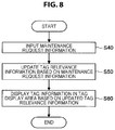
(1-6-1. Overview of Process)
In this regard, first, an overview of the maintenance process will be described with reference to a flowchart illustrated in FIG. 8. In step S40, the user performs an input operation indicating that the maintenance is requested. Accordingly, the control unit 40 e generates maintenance request information, and outputs the maintenance request information to the communication unit 40 d. The communication unit 40 d transmits the maintenance request information to the tag processing server 10. The communication unit 10 b of the tag processing server 10 receives the maintenance request information, and outputs the maintenance request information to the control unit 10 c.
In step S50, the control unit 10 c acquires the tag relevance information from the tag management server 20, and updates the tag relevance information based on the maintenance request information. In step S60, the control unit 10 c outputs the updated tag relevance information to the communication unit 10 b. The communication unit 10 b transmits the tag relevance information to the tag management server 20 and the user terminals 40. The tag management server 20 stores the tag relevance information. On the other hand, the user terminals 40 causes the tag information to be displayed in the tag relevance information display area 300 based on the updated tag relevance information. Thereafter, the information processing system 1 ends the present process. As described above, when any one user performs the maintenance process, the result can be shared with other users. A specific example of the maintenance process will be described.
(1-6-2. Tag Association Process)
When a plurality of pieces of tag information are displayed in the tag relevance information display area 300, the user can associate the tag information. For example, when the tag information 400 a and 400 b is displayed in the tag relevance information display area 300 as illustrated in FIG. 16, the user can associate the tag information 400 a and 400 b. The tag information 400 b indicates tag information “BBB.”
Specifically, the user taps the maintenance icon 320 illustrated in FIG. 16. The maintenance icon 320 is a pen type icon. Accordingly, the control unit 40 e causes the maintenance icon 320 to be highlighted. For example, the control unit 40 e causes the maintenance icon 320 to be surrounded by a frame image 320 a. Of course, the highlighting is not limited to this example. As another example of the highlighting, there are an enlarged display, a display of a different color, a blinking display, and the like. Then, the user drags a finger from one tag information to the other tag information among a plurality of pieces of tag information that are desired to be associated. For example, when the tag information 400 a and the tag information 400 b are desired to be associated, the user taps the tag information 400 a (or the tag information 400 b), and then drags the finger up to the tag information 400 b (or the tag information 400 a). Accordingly, the control unit 40 e generates the maintenance request information indicating that a plurality of pieces of tag information designated by the user are associated. Then, the control unit 40 e outputs the maintenance request information to the communication unit 40 d, and the communication unit 40 d transmits the maintenance request information to the tag processing server 10.
The communication unit 10 b of the tag processing server 10 receives the maintenance request information, and outputs the maintenance request information to the control unit 10 c. The control unit 10 c acquires the tag relevance information from the tag management server 20. Then, the control unit 10 c updates the tag relevance information based on the maintenance request information. Specifically, the control unit 10 c specifies a plurality of pieces of tag information that are requested to be associated. Then, the control unit 10 c stores the tag ID of the other tag information in the tag relevance field corresponding to one tag information. Similarly, the control unit 10 c stores the tag ID of one tag information in the tag relevance field corresponding to the other tag information. For example, the control unit 10 c causes the tag ID of the tag information 400 b to be stored in the tag relevance field corresponding to the tag information 400 a, and causes the tag ID of the tag information 400 a to be stored in the tag relevance field corresponding to the tag information 400 b. Then, the control unit 10 c outputs the updated tag relevance information to the communication unit 10 b. The communication unit 10 b transmits the tag relevance information to the tag management server 20 and the user terminals 40.
The tag management server 20 stores the tag relevance information. The communication unit 40 d of the user terminal 40 receives the tag relevance information, and outputs the tag relevance information to the control unit 40 e. The control unit 40 e causes the tag information to be displayed based on the tag relevance information. Here, the control unit 40 e causes the connection information to be displayed based on the tag ID of the tag relevance field. The connection information is line information that connecting the tag information that is associated with each other. FIG. 17 illustrates a display example. In this example, the tag information 400 a and 400 b are connected through the connection information 410.
The information processing system 1 can cause a plurality of pieces of tag information to be displayed in the tag relevance information display area 300 and associate the tag information with one another by repeatedly performing the tag relevance information generation process and the tag association process. FIGS. 19 and 20 illustrate examples in which a plurality of pieces of tag information is displayed in the tag relevance information display area 300. In FIG. 19, a plurality of pieces of tag information 400 a to 400 j are displayed in the tag relevance information display area 300, and the tag information that is associated with each other among the tag information 400 a to 400 j is connected through the connection information 410. The tag information 400 c to 400 j is tag information “CCC” to “JJJ.” In FIG. 20, a plurality of pieces of tag information 400 a to 400 j and 400A are displayed in the tag relevance information display area 300. The tag information 400A indicates character information such as “AAA,” similarly to the tag information 400 a. However, the sub name information is different. Thus, the tag information 400 a and 400A are different tag information. According to the tag association process, a plurality of users associate a plurality of pieces of tag information, and thus each user can refer to associations performed by other users. As a result, each user can have a new idea about the relevance between the tag information.
When a plurality of pieces of tag information is displayed in the tag relevance information display area 300 as illustrated in FIGS. 19 and 20, the user may feel cumbersome. In this regard, the control unit 40 e may cause only tag information input by the user and tag information associated with the tag information to be displayed in the tag relevance information display area 300. Here, when a plurality of pieces of tag information are connected through the connection information using the tag information input by the user as a basic point, the control unit 10 c may cause all of the tag information to be displayed. For example, when the user inputs the tag information 400 a illustrated in FIG. 19, the control unit 10 c may cause the tag information 400 b to 400 j connected with one another using the tag information 400 a as the basic point to be displayed in the tag relevance information display area 300. Further, even when the user is inputting the tag information, the control unit 40 e may perform predictive conversion on the tag information and cause only the tag information that has undergone the predictive conversion and tag information associated with the tag information to be displayed in the tag relevance information display area 300.
The control unit 40 e may cause the frequency of use of the tag information by the user to be stored in the storage unit 40 a and change the display position of the tag information based on the frequency of use of the tag information. For example, the control unit 40 e may cause the display position of the tag information to get closer to the center of the tag relevance information display area 300 as the frequency of use of the tag information by the user increases. The control unit 10 c of the tag processing server 10 may collect the frequency of use of the tag information by all the users and change a value of the coordinates field in the tag relevance information according to the result. For example, the control unit 10 c causes the display position of the tag information to get closer to the center of the tag relevance information display area 300 as the frequency of use of the tag information by all the users increases.
The information processing system 1 may adjust a degree of relevance between the tag information based on the input operation from the user. For example, when the user desires to adjust a degree of relevance between the tag information, the user taps the connection information connecting the tag information with each other. For example, when the user desires to adjust the relevance of the tag information 400 a and 400 b illustrated in FIG. 17, the user taps the connection information 410 connecting the tag information 400 a and 400 b. Accordingly, the control unit 10 c generates maintenance request information indicating that the relevance of the tag information is highlighted. The control unit 10 c outputs the maintenance request information to the communication unit 40 d. The communication unit 40 d transmits the maintenance request information to the tag processing server 10.
The communication unit 10 b of the tag processing server 10 receives the maintenance request information, and outputs the maintenance request information to the control unit 10 c. The control unit 10 c acquires the tag relevance information from the tag management server 20. Then, the control unit 10 c updates the tag relevance information based on the maintenance request information. Specifically, the control unit 10 c specifies the tag ID of the tag information whose association is requested to be highlighted. Then, the control unit 10 c assigns highlighting information to the specified tag ID in the tag relevance field. FIG. 10 illustrates an example of the highlighting information. In this example, the relevance of the tag information 400 a and 400 b is highlighted. The highlighting information is indicated by a mark *. Then, the control unit 10 c outputs the updated tag relevance information to the communication unit 10 b. The communication unit 10 b transmits the tag relevance information to the tag management server 20 and the user terminals 40.
The tag management server 20 stores the tag relevance information. The communication unit 40 d of the user terminal 40 receives the tag relevance information, and outputs the tag relevance information to the control unit 40 e. The control unit 40 e causes the tag information to be displayed based on the tag relevance information. Here, the control unit 40 e causes the connection information to be displayed based on the tag ID in the tag relevance field. Further, when the highlighting information is assigned to the tag ID in the tag relevance field, the control unit 40 e causes the connection information corresponding to the highlighting information to be highlighted. For example, when the highlighting information is assigned to the relevance of the tag information 400 a and 400 b illustrated in FIG. 16, the control unit 40 e causes the connection information 410 connecting the tag information 400 a and 400 b to be highlighted as illustrated in FIG. 18. For example, the control unit 40 e causes the connection information 410 to be displayed with a heavy line. The example of the highlighting is not limited thereto. For example, the control unit 40 e may cause the connection information 410 to be displayed in a different color from that of other connection information 410. The control unit 40 e may cause the connection information 410 indicating specific relevance to be displayed in a specific color. The control unit 10 c of the tag processing server 10 may adjust the degree of the relevance, for example, according to the number of taps of the user on the connection information. In this case, the control unit 40 e of the user terminal 40 may adjust a degree of the highlighting according to the degree of the relevance. A priority of the user may be set. For example, when the first embodiment is applied to an SNS in a hospital, a priority of doctors may be set to be higher than a priority of patients. The control unit 40 e may cause the connection information generated according to the maintenance request information transmitted from the user having a high priority to be more highlighted than the connection information generated according to the maintenance request information transmitted from the user having a low priority. In this case, the tag ID and the priority of the user who has requested the relevance are associated and stored in the relevance field of the tag relevance information.
(1-6-3. Folder Management Process)
When one or more pieces of tag information are displayed in the tag relevance information display area 300, the user can store the tag information in the tag folder. For example, when tag information 400 k to 400 n and 430 a to 430 c are displayed in the tag relevance information display area 300 as illustrated in FIG. 21, the user can arrange the tag information 430 a to 430 c in the tag folder. Here, the tag information 400 k to 400 n is tag information indicating “KKK” to “NNN.” The tag information 430 a is tag information indicating “dog,” the tag information 430 b is tag information indicating “DOG” and the tag information 430 c is tag information indicating “Dog.” The tag information has the same meaning and is all associated with the tag information 400 k to 400 n. FIG. 11 illustrates an example of the tag relevance information corresponding to the display example of FIG. 21.
Therefore, since the tag information is arranged in one tag folder (that is, hierarchized), they can be dealt with as the same meaning at the time of the search process. In other words, the accuracy of the search process is improved. There is a merit in that the tag information of the tag relevance information display area 300 is organized.
Specifically, the user inputs the object information including arbitrary tag information (preferably, the tag information serving as a generic term of the tag information that is desired to be arranged in the tag folder. Hereinafter, the tag information is also referred to as “tag folder creation tag information”) to the user terminal 40. Accordingly, the information processing system 1 performs the tag relevance information generation process, registers the tag folder creation tag information input by the user in the tag relevance information, and the tag folder creation tag information to be displayed in the tag relevance information display area 300. Then, the user drags the tag folder creation tag information in the tag relevance information display area 300 and drops it on the maintenance icon 310. The user may drag the maintenance icon 310 and drop it on the tag folder creation tag information.
Accordingly, the control unit 40 e generates maintenance request information indicating that the tag folder is requested to be created, and outputs the maintenance request information to the communication unit 40 d. The communication unit 40 d transmits the maintenance request information to the tag processing server 10. The communication unit 10 b of the tag processing server 10 outputs the maintenance request information to the control unit 10 c. The control unit 10 c acquires the tag relevance information from the tag management server 20. Then, the control unit 10 c causes the tag folder information to be stored in the tag content field corresponding to the tag folder creation tag information among the tag relevance information. The tag folder information is information indicating that the tag information is the tag folder. FIG. 12 illustrates an example of the tag folder information. FIG. 12 is an example of the tag relevance information, and tag information corresponding to the tag ID 10007 is the tag folder. In the tag content field corresponding to the tag ID 10007, the tag folder information is indicated by a mark *.
Then, the control unit 10 c outputs the updated tag relevance information to the communication unit 10 b. The communication unit 10 b transmits the tag relevance information to the tag management server 20 and the user terminals 40. The tag management server 20 stores the tag relevance information. The communication unit 40 d of the user terminal 40 receives the tag relevance information, and outputs the tag relevance information to the control unit 40 e. The control unit 40 e causes the tag information to be displayed based on the tag relevance information. Here, the control unit 40 e converts the tag information included in the tag folder information in the tag content field into the tag folder.
For example, when the user creates the tag folder 500 a indicating “DOG” as illustrated in FIG. 22, the object information including tag information 230 indicating “# DOG” is input to the user terminal 40. Accordingly, the information processing system 1 causes the tag folder creation tag information written as “DOG” to be displayed in the tag relevance information display area 300. Thereafter, the user drags the tag folder creation tag information and drops it on the maintenance icon 310. Accordingly, the information processing system 1 converts the tag folder creation tag information into the tag folder 500 a.
Then, the user stores desired tag information in the tag folder. Specifically, the user drags desired tag information and drops it in the tag folder. For example, when the user desires to store the tag information 430 a to 430 c in the tag folder 500 a in the example illustrated in FIG. 22, the user drags the tag information 430 a to 430 c and drops it in the tag folder 500 a as indicated by an arrow P. Accordingly, the control unit 40 e generates maintenance request information indicating that the tag information is requested to be stored in the tag folder, and outputs the maintenance request information to the communication unit 40 d. The maintenance request information indicates the tag information designated by the user and a tag folder in which the tag information is stored.
The communication unit 40 d transmits the maintenance request information to the tag processing server 10. The communication unit 10 b of the tag processing server 10 outputs the maintenance request information to the control unit 10 c. The control unit 10 c acquires the tag relevance information from the tag management server 20. Then, the control unit 10 c specifies the tag information and the tag folder indicated by the maintenance request information among the tag relevance information. Then, the control unit 10 c causes the tag ID of the specified tag folder to be stored in the layer field of the specified tag information. As a result, the tag information designated by the user is stored in the tag folder (that is, the tag information is arranged in a layer lower than the tag folder). Information stored in the layer field may be tag content of the tag folder. FIG. 12 illustrates an example. In this example, tag information (that is, the tag information 430 a to 430 c) of tag IDs 10001 to 10003 is stored in the tag folder (that is, the tag folder 500 a) of the tag ID 10007.
Further, when the tag information stored in the tag folder is associated with other tag information, the control unit 10 c determines the tag folder to be also associated with the tag information. The control unit 10 c causes the tag ID of the tag information associated with the tag folder to be stored in the tag relevance field corresponding to the tag folder. FIG. 12 illustrates an example. In this example, the tag information 430 a to 430 c is stored in the tag folder 500 a, but the tag information 430 a to 430 c is associated with the tag information (that is, the tag information 400 k to 400 n) of the tag IDs 10004 to 10006. Therefore, the tag IDs 10004 to 10004 are stored in the tag relevance field of the tag folder 500 a. The tag IDs 10004 to 10006 are stored in the tag relevance fields of the tag information 430 a to 430 c. A character “-” is added to the end of the tag IDs 10004 to 10006. This character indicates, for example, that the connection information indicating the tag relevance may be omitted. Then, the control unit 10 c outputs the updated tag relevance information to the communication unit 10 b. The communication unit 10 b transmits the tag relevance information to the tag management server 20 and the user terminals 40.
The tag management server 20 stores the tag relevance information. The communication unit 40 d of the user terminal 40 receives the tag relevance information, and outputs the tag relevance information to the control unit 40 e. The control unit 40 e causes the tag information to be displayed based on the tag relevance information. Here, the control unit 40 e causes the tag information in which the tag folder information is stored in the tag content field to be displayed as the tag folder. The control unit 40 e causes the tag information to be stored in the tag folder with reference to the layer field. When the tag relevance information illustrated in FIG. 12 is assigned, the control unit 40 e creates the tag folder 500 a and causes the tag information 430 a to 430 c to be stored in the tag folder 500 a as illustrated in FIG. 23. Further, the control unit 40 e associates the tag folder with other tag information with reference to the tag relevance field of the tag folder. In the tag relevance information illustrated in FIG. 12, since the tag IDs 10004 to 10006 (that is, the tag information 400 k to 400 n) are stored in the tag relevance field corresponding to the tag folder 500 a, the control unit 40 e associates the tag folder 500 a with the tag information 400 k to 400 n. Specifically, the control unit 40 e connects the tag folder 500 a with the tag information 400 k to 400 n using the connection information 410. The control unit 40 e causes an open designation icon 510 to be arranged nearby the tag folder 500 a.
When the user taps the open designation icon 510, the control unit 40 e opens the tag folder 500 a and causes the tag information 430 a to 430 c in the tag folder 500 a to be displayed as illustrated in FIG. 24. Specifically, the control unit 40 e causes a tag folder display area 530 a to be set below a tag folder 530, and causes the tag information 430 a to 430 c to be displayed in the tag folder display area 530 a. As a result, the control unit 40 e can display the tag folder 500 a and the tag information 430 a to 430 c to be associated. Here, the control unit 40 e may connect the tag information 430 a to 430 c with the tag information 400 k to 400 n associated with the tag information 430 a to 430 c using the connection information 410. The connection information 410 may be omitted. As illustrated in FIG. 24, the connection information 410 may be displayed in a form (for example, a broken line or the like) that is less noticeable than the connection information 410 extending from the tag folder 500 a.
The control unit 40 e causes a close designation icon 520 to be displayed nearby the tag folder 500 a while the tag folder 500 a is being opened. The control unit 40 e closes the tag folder 500 a when the user taps the close designation icon 520. Specifically, the control unit 40 e causes an image illustrated in FIG. 23 to be displayed.
In the above example, only the tag information is stored in the tag folder, but the tag folder may be further stored in the tag folder. Here, when a certain tag folder is not stored in another tag folder, the tag folder is the top tag folder. The tag information stored in the top tag folder and the tag folder are tag information and a tag folder in a first layer. The tag information stored in the tag folder in the first layer and the tag folder are tag information and a tag folder in a second layer. Thereafter, counting is performed through the same process.
In the above example, the tag information having the same meaning but different notations is arranged in one tag folder, but it will be appreciated that the use of the tag folder is not limited thereto. For example, the user may create a tag folder indicating a project name and sequentially store tag information generated in the project in the tag folder. In this case, for example, when the project name is changed, the user preferably changes a name of the tag folder to a new project name. Then, the user preferably stores tag information generated after the project name is changed in the same tag folder as well. As a result, the tag information before and after the project name is changed is stored in the same tag folder. Then, for example, in the search process, the information processing system 1 can use both of the tag information before the change and the tag information after the change as the search word. Further, there is a merit in that the tag information of the tag relevance information display area 300 is organized. The user can determine that the tag information before the project is changed and the tag information after the project is changed belong to the same project.
Further, when the user is developing a product, the user may create a tag folder indicating a development code and stores tag information that is generated during the development in the tag folder. In this case, for example, when a product name is decided, the user preferably change a name of the tag folder from the development code to the product name. Then, the user preferably stores tag information generated after the product name is decided in the same tag folder as well. As a result, the tag information corresponding to the development code and the tag information corresponding to the product name are stored in the same tag folder. Then, for example, in the search process, the information processing system 1 can use both of the tag information corresponding to the development code and the tag information corresponding to the product name as the search word. Further, there is a merit in that the tag information of the tag relevance information display area 300 is organized. The user can determine that the tag information corresponding to the development code and the tag information corresponding to the product name are associated with the same product.
The user may create the tag folder indicating the project name for each project. Then, when a plurality of projects are integrated into one project, the user may create a tag folder indicating a project name after the integration and store a plurality of tag folders before the integration in the tag folder. As a result, the tag information generated in each of the projects before the integration and the tag information generated in the project after the integration are stored in the same tag folder. Then, for example, in the search process, the information processing system 1 can use both of the tag information corresponding to the projects before the integration and the tag information corresponding to the project after the integration as the search word. Further, there is a merit in that the tag information of the tag relevance information display area 300 is organized. The user can determine that the tag information corresponding to the projects before the integration and the tag information corresponding to the project after the integration belong to the same project.
Further, when there are a plurality of names (for example, formal name, a nickname, or the like) as a name of a certain subject (for example, a person, a geographical name, a product name, or the like), the user may create a tag folder indicating a representative one of the names. Then, the user may store tag information indicating each name in the tag folder. In this case, for example, in the search process, the information processing system 1 can use various names as the search word together. Further, there is a merit in that the tag information of the tag relevance information display area 300 is organized. The user can determine that a plurality of pieces of tag information indicate the same subject.
(1-6-4. Browsing Restriction Setting Process)
The user may set a browsing restriction in the tag folder. For example, in the example illustrated in FIG. 23, the user may set the browsing restriction in the tag folder 500 a. In this case, browsing of the tag information 430 a to 430 c stored in the tag folder 500 a is restricted. As an example in which the browsing restriction is used, tag information related to a specific project is permitted to be browsed by a certain user involved in the project.
Specifically, the user drags the tag folder on which the browsing restriction is desired to be set and drops it on the maintenance icon 340. The user may drag the tag folder and drop it on the maintenance icon 340. For example, the user drags the tag folder 500 a and drops it on the maintenance icon 340.
Accordingly, the control unit 40 e asks the user about the user to whom a permission for browsing (access) is given. For example, the control unit 40 e causes a message window 700 illustrated in FIG. 26 to be displayed. Character information for asking about the user to whom a permission for browsing is given and a user input field 710 are displayed on the message window 700. The user inputs the user to whom a permission for browsing is given to the user input field 710. For example, the user inputs the user ID of the user to whom a permission for browsing is given (which may be a mail address, a mailing list, a global ID, or the like).
Accordingly, the control unit 40 e generates maintenance request information indicating that the browsing restriction is requested to be set, and outputs the maintenance request information to the communication unit 40 d. The maintenance request information indicates a tag folder serving as a browsing restriction setting target (hereinafter, also referred to as a “browsing restriction tag folder”) and the user ID of the user to whom a permission for browsing is given. The communication unit 40 d transmits the maintenance request information to the tag processing server 10. The communication unit 10 b of the tag processing server 10 outputs the maintenance request information to the control unit 10 c. The control unit 10 c acquires the tag relevance information from the tag management server 20. Then, the control unit 10 c specifies the browsing restriction tag folder based on the maintenance request information.
Then, the control unit 10 c assigns browsing restriction information to the tag content field of the browsing restriction tag folder. Further, the control unit 10 c causes a name of the user who gets a permission for browsing to be stored in a user field of browsing restriction tag information. Further, the control unit 10 c specifies the browsing restriction tag information stored in the tag folder (hereinafter, also referred to as “browsing restriction tag information”) based on the tag relevance field of the browsing restriction tag folder. Further, the control unit 10 c assigns the browsing restriction information to the tag ID stored in the tag relevance field of the browsing restriction tag information. Further, the control unit 10 c assigns the browsing restriction information to the tag ID indicating the browsing restriction tag information among the tag IDs stored in the tag relevance fields of other tag information.
FIG. 13 illustrates a specific example. In this example, the tag folder indicated by the tag ID 10007 (that is, the tag folder 500 a) is the browsing restriction tag folder. Thus, the control unit 10 c assigns the browsing restriction information to the tag content field of the tag folder 500 a. The browsing restriction information is indicated by a mark “N.” Further, the control unit 10 c causes the name of the user who gets a permission for browsing to be stored in the user field of the tag folder 500 a. In this example, “Yano,” “Suzuki,” “oba,” and “ohtani” are permitted for browsing.
Further, the tag information indicated by the tag IDs 10004 to 10006 (that is, the tag information 430 a to 430 c) is the browsing restriction tag information. In this regard, the control unit 10 c assigns the browsing restriction information to the tag IDs stored in the tag relevance fields of the tag information 430 a to 430 c. The control unit 10 c assigns the browsing restriction information to the tag IDs indicating the tag information 430 a to 430 c among the tag IDs stored in the tag relevance fields of other tag information (the tag information 400 k to 400 n).
Then, the control unit 10 c outputs the updated tag relevance information to the communication unit 10 b. The communication unit 10 b transmits the tag relevance information to the tag management server 20 and the user terminals 40. The tag management server 20 stores the tag relevance information. The communication unit 40 d of the user terminal 40 receives the tag relevance information, and outputs the tag relevance information to the control unit 40 e. The control unit 40 e causes the tag information to be displayed based on the tag relevance information. Here, the control unit 40 e causes the tag folder in which the browsing restriction information is stored in the tag content field to be displayed as the browsing restriction tag folder. For example, when the tag relevance information illustrated in FIG. 13 is assigned, the control unit 40 e sets the tag folder 500 a as the browsing restriction tag folder as illustrated in FIG. 27. Specifically, the control unit 40 e causes a browsing restriction icon 540 to be displayed nearby the tag folder 500 a.
Then, when the user taps the open designation icon 510 of the tag folder 500 a, the control unit 40 e determines whether or not the user is the user who gets a permission for browsing. Specifically, the control unit 40 e acquires the user ID from the storage unit 40 a, and determines whether or not the name corresponding to the user ID is stored in the user field of the tag folder 500 a. When the name corresponding to the user ID is stored in the user field of the tag folder 500 a, the control unit 40 e determines the user to be the user who gets a permission for browsing. Otherwise, the control unit 40 e determines the user not to get a permission for browsing.
For the user who gets a permission for browsing, the control unit 40 e opens the tag folder 500 a as illustrated in FIG. 28. The control unit 40 e causes the connection information 410 connecting the browsing restriction tag information with other tag information to be displayed as well. On the other hand, for the user who does not get a permission for browsing, the control unit 40 e does not open the tag folder 500 a as illustrated in FIG. 29. Then, the control unit 40 e causes a message window 720 indicating that the browsing is restricted to be displayed. As illustrated in FIG. 29, even for the user who does not get a permission for browsing, the control unit 40 e causes the connection information 410 connecting the browsing restriction tag folder with the other tag information 400 k to 400 n to be displayed. Therefore, the user can recognize at least that the browsing restriction tag folder is associated with the other tag information 400 k to 400 n. As a result, when the user gets a permission for browsing later, the relevance between the browsing restriction tag information and other tag information can be easily understood.
The user can abolish the browsing restriction at an arbitrary timing. For example, the user holds down the browsing restriction tag folder. Accordingly, the control unit 40 e generates maintenance request information indicating that the browsing restriction of the browsing restriction tag folder is requested to be abolished. Then, the control unit 40 e outputs the maintenance request information to the communication unit 40 d. The communication unit 40 d transmits the maintenance request information to the tag processing server 10. The communication unit 10 b of the tag processing server 10 receives the maintenance request information, and outputs the maintenance request information to the control unit 10 c. The control unit 10 c abolishes the browsing restriction of the browsing restriction tag folder based on the maintenance request information. Specifically, the control unit 10 c deletes the browsing restriction information from the tag content field of the browsing restriction tag folder. The control unit 10 c deletes the browsing restriction information from the tag relevance field of the browsing restriction tag information. Further, the control unit 10 c deletes the browsing restriction information even from the tag relevance fields of other tag information. Then, the control unit 10 c outputs the updated tag relevance information to the communication unit 10 b. The communication unit 10 b transmits the tag relevance information to the tag management server 20 and the user terminals 40. The tag management server 20 stores the tag relevance information. The communication unit 40 d of the user terminal 40 receives the tag relevance information, and outputs the tag relevance information to the control unit 40 e. The control unit 40 e causes the tag information to be displayed based on the tag relevance information. Specifically, the control unit 40 e returns the browsing restriction tag folder to a normal tag folder (without browsing restriction).
The information processing system 1 may receive a change in the user to whom a permission for browsing is given. In other words, when there is a predetermined operation (for example, an operation of tapping the browsing restriction tag folder twice or more), the control unit 40 e may cause the message window 700 illustrated in FIG. 26 to be displayed. Thereafter, the information processing system 1 may change (reset) the user to whom a permission for browsing is given by performing the above-described process.
(1-6-5. Recommendation Process)
The tag processing server 10 causes a tag folder serving as a hierarchization candidate (hereinafter, also referred to as a “hierarchization candidate tag folder”) to be displayed based on the tag relevance information. Specifically, the control unit 10 c acquires the tag relevance information from the tag management server 20, and specifies a plurality of pieces of tag information associated with the same tag information based on the tag relevance information. Then, the control unit 10 c creates the hierarchization candidate tag folder including the specified tag information.
FIG. 30 illustrates an example. In this example, a plurality of pieces of tag information 400 a to 400 c are associated with the same tag information 400 d to 400 e. Similarly, a plurality of pieces of tag information 400 d to 400 e are associated with the same tag information 400 a to 400 c. In this regard, the control unit 10 c creates the hierarchization candidate tag folder 610 a including a plurality of pieces of tag information 400 d to 400 e and the hierarchization candidate tag folder 610 b including a plurality of pieces of tag information 400 a to 400 c as illustrated in FIG. 31.
Then, the control unit 10 c outputs hierarchization candidate information associated with the hierarchization candidate tag folder to the communication unit 10 b. The communication unit 10 b transmits the hierarchization candidate information to the user terminals 40. The communication unit 40 d of the user terminal 40 receives the hierarchization candidate information, and outputs the hierarchization candidate information to the control unit 40 e. The control unit 40 e sets the recommendation area 600 in the tag relevance information display area 300, and causes the hierarchization candidate tag folder to be displayed in the recommendation area 600 as illustrated in FIG. 31. The control unit 40 e causes the tag information in the hierarchization candidate tag folder to be displayed as well when the hierarchization candidate tag folder is displayed. For example, the control unit 40 e causes the hierarchization candidate tag folders 610 a and 610 b to be displayed in the recommendation area 600. Further, the control unit 40 e causes the tag information 400 d to 400 e in the hierarchization candidate tag folder 610 a to be displayed nearby the hierarchization candidate tag folder 610 a. Further, the control unit 40 e causes the tag information 400 a to 400 c in the hierarchization candidate tag folder 610 b to be displayed nearby the hierarchization candidate tag folder 610 b.
Then, the user taps any one hierarchization candidate tag folder and selects the hierarchization candidate tag folder. Further, the user inputs a name of the hierarchization candidate tag folder (the tag information of the tag folder itself). Accordingly, the control unit 40 e generates maintenance request information indicating that the hierarchization candidate tag folder designated by the user is used as a formal tag folder. The maintenance request information indicates the hierarchization candidate tag folder designated by the user and the name. The maintenance request information includes the user ID. The control unit 40 e outputs the maintenance request information to the communication unit 40 d. The communication unit 40 d transmits the maintenance request information to the tag processing server 10. The communication unit 10 b of the tag processing server 10 receives the maintenance request information, and outputs the maintenance request information to the control unit 10 c.
The control unit 10 c acquires the tag relevance information from the tag management server 20. Then, a new line is added to the tag relevance information, and information related to the hierarchization candidate tag folder is stored in this line. Specifically, the control unit 10 c causes a newly created tag ID to be stored in the tag ID field. The control unit 10 c extracts the user ID from the maintenance request information, and acquires the name information corresponding to the user ID from the tag management server 20. Then, the control unit 10 c causes the name information to be stored in the creator field and the user field. The control unit 10 c specifies the tag information associated with the tag information included in the hierarchization candidate tag folder. Then, the control unit 10 c causes the tag ID indicating the specified tag information to be stored in the relevance field. The control unit 10 c causes the display coordinates that do not overlap the display coordinates of the other tag information to be stored in the coordinates field. The control unit 10 c causes the layer field to be blank. Further, the control unit 10 c specifies the tag information included in the hierarchization candidate tag folder, and causes the tag ID of the hierarchization candidate tag folder to be stored in the layer field of the tag information. As a result, the control unit 10 c recognizes the hierarchization candidate tag folder as a formal tag folder, and registers the hierarchization candidate tag folder in the tag relevance information.
Then, the control unit 10 c outputs the updated tag relevance information to the communication unit 10 b. The communication unit 10 b transmits the tag relevance information to the tag management server 20 and the user terminals 40. The tag management server 20 stores the tag relevance information. The communication unit 40 d of the user terminal 40 receives the tag relevance information, and outputs the tag relevance information to the control unit 40 e. The control unit 40 e causes the tag information to be displayed in the tag relevance information display area 300 based on the tag relevance information. FIG. 32 illustrates a specific example. In this example, the user selects the hierarchization candidate tag folder 610 a, and a name thereof is “FFF.” Therefore, the control unit 40 e causes the tag folder 500 f corresponding to the hierarchization candidate tag folder 610 a to be displayed in the tag relevance information display area 300. The information processing system 1 may automatically select any one hierarchization candidate folder as a formal tag folder. For example, the information processing system 1 may automatically select a folder that is smallest (or largest) in the tag information included in the hierarchization candidate tag folder as a formal tag folder. In the information processing system 1, the hierarchization candidate tag folder may be displayed one by one, and a message window in which character information such as “Do you want to hierarchize?” is written may be displayed for each folder. A “YES” button and a “NO” button are displayed on the message window. In the information processing system 1, the hierarchization candidate tag folder may be selected as the formal tag folder when the user taps the “YES” button. Through this process, in the information processing system 1, a highly accurate recommendation can be given.
1-7. Search Process
In the information processing system 1, the efficient search process can be performed based on the tag relevance information that is generated and updated through the tag relevance information generation process and the maintenance process. The search process is performed for each user terminal 40. In other words, a result of performing the search process through the user using the user terminal 40 is not reflected in the other user terminals 40. Of course, the result of performing the search process through the user using the user terminal 40 may be reflected in the other user terminals 40. Content of the search process will be described below with reference to a flowchart illustrated in FIG. 9. Here, the search process will be described under the assumption that the tag information 430 a to 430 c and 400 k to 400 n and the tag folder 500 a illustrated in FIG. 33 are displayed in the tag relevance information display area 300. At the time of the search process, the maintenance icons 310 to 340 may be erased.
In step S10, the control unit 40 e of the user terminal 40 determines whether or not the user has tapped the search button 350. The control unit 40 e causes the process to proceed to step S80 when the user is determined to have tapped the search button 350 and end the present process when the user is determined not to have tapped the search button 350.
In step S80, the control unit 40 e causes the search button 350 to be highlighted. For example, the control unit 40 e causes the search button 350 to be surrounded by a frame image 351 as illustrated in FIG. 33. Of course, the highlighting method is not limited to this example. As another example of highlighting the search button 350, there are a process of drawing the search button 350 with a heavy line, a process of blinking the search button 350, and a process of enlarging and displaying the search button 350. As another example, there is a process of displaying the search button 350 in a different color from that in a normal state (a non-tapped state).
Then, the control unit 40 e is on standby until the user taps any tag information or the tag folder. When the user taps any tag information or the tag folder, the control unit 40 e causes the process to proceed to step S90.
In step S90, the control unit 40 e determines whether or not the tag folder has been tapped in step S80. The control unit 40 e causes the process to proceed to step S100 when the tag folder has been tapped in step S80 and causes the process to proceed to step S130 when the tag information has been tapped in step S80.
In step S100, the control unit 40 e sets the tag folder and all the tag information in the tag folder as the search word, and highlights the tag folder and all the tag information in the tag folder. For example, when the tag folder 500 a illustrated in FIG. 33 has been tapped, the control unit 40 e sets the tag folder 500 a and all the tag information 430 a to 430 c in the tag folder 500 a as the search word. Then, the control unit 40 e highlights the tag folder 500 a and the tag information 430 a to 430 c. In FIG. 33, the tag folder 500 a and the tag information 430 a to 430 c are displayed to blink. Of course, the highlighting method is not limited to this example. As another example of highlighting the tag information or the like, there are a process of enlarging and displaying the tag information or the like, a process of displaying the tag information or the like in a different color from that in a normal state (a state in which it is not a search word), and a process of drawing the tag information or the like with a heavy line. The control unit 40 e causes the tag information and the tag folder serving as the search word to be displayed near the center of the tag relevance information display area 300. When there is tag information having the same content as the tag folder, the tag information may be also displayed near the center of the tag relevance information display area 300.
In step S110, the control unit 40 e determines whether or not the user has tapped any tag information in the tag folder. The control unit 40 e causes the process to proceed to step S120 when the user has tapped any tag information in the tag folder and causes the process to proceed to step S140 when the user has not tapped any tag information in the tag folder.
In step S120, the control unit 40 e excludes the tag information tapped by the user from the search word, and stops the tag information from being highlighted. For example, when the user has tapped the tag information 430 c illustrated in FIG. 33, the control unit 40 e excludes the tag information 430 c from the search word. Further, the control unit 40 e stops the tag information 430 c from being highlighted as illustrated in FIG. 34. Thereafter, the control unit 40 e causes the process to proceed to step S140.
In step S140, the control unit 40 e generates search request information including the search word, and outputs the search request information to the communication unit 40 d. Then, the communication unit 40 d transmits the search request information to the tag processing server 10. The communication unit 10 b of the tag processing server 10 receives the search request information, and outputs the search request information to the control unit 10 c. The control unit 10 c specifies the search word based on the search request information. Then, the control unit 10 c acquires the SNS information including the tag information as the search word from the SNS information in the tag management server 20. Then, the control unit 10 c outputs the acquired SNS information to the communication unit 10 b. The communication unit 10 b transmits the SNS information to the user terminal 40 that has made the search request. The communication unit 40 d of the user terminal 40 receives the SNS information, and outputs the SNS information to the control unit 40 e. The control unit 40 e causes the SNS information to be displayed in the SNS display area 200. FIGS. 33 and 34 illustrate display examples. In the example illustrated in FIG. 33, since the tag folder 500 a and the tag information 430 a to 430 c are set as the search word, the SNS information including the tag information as the search word is displayed in the SNS display area. In the example illustrated in FIG. 34, since the tag folder 500 a and the tag information 430 a to 430 b are set as the search word, the SNS information including the tag information as the search word is displayed in the SNS display area. Thereafter, the information processing system 1 ends the present process.
1-8. Other Processes
(1-8-1. Tag Creation Using Maintenance Icon)
Next, other processes will be described. First, the tag creation using the maintenance icon 330 will be described. In the above-described process, in the information processing system 1, when the user inputs the object information including the tag information to the user terminal 40, the tag information is displayed in the tag relevance information display area 300. However, the user may directly create the tag information using the maintenance icon 330 instead of inputting the object information.
Specifically, the user taps the maintenance icon 330 illustrated in FIG. 14. Accordingly, the control unit 40 e causes a message window indicating that the name of the tag information is requested to be input to be displayed. Accordingly, the user inputs the name of the tag information. Then, the control unit 40 e creates maintenance request information indicating that the tag information is requested to be created, and outputs the maintenance request information to the communication unit 40 d. The name of the tag information and the user ID are included in the maintenance request information. The communication unit 40 d transmits the maintenance request information to the tag processing server 10. The communication unit 10 b of the tag processing server 10 receives the maintenance request information, and outputs the maintenance request information to the control unit 10 c. The control unit 10 c performs the same process as the tag relevance information generation process, and registers the tag information in the tag relevance information. Then, the control unit 10 c outputs the updated tag relevance information to the communication unit 10 b. The communication unit 10 b transmits the tag relevance information to the tag management server 20 and the user terminals 40. The tag management server 20 stores the tag relevance information. The communication unit 40 d of the user terminal 40 receives the tag relevance information, and outputs the tag relevance information to the control unit 40 e. The control unit 40 e causes the tag information to be displayed in the tag relevance information display area 300 based on the tag relevance information. Therefore, the tag information input by the user is included in the tag relevance information display area 300. The tag information may not be associated with the object information in the SNS display area 200.
(1-8-2. Maintenance-Specialized User)
One of a plurality of user terminals 40 may be the user terminal 40 that is specialized in the maintenance. A user who uses such a user terminal 40 is a maintenance-specialized user. The tag processing server 10 may transmit only the tag relevance information to the user terminal 40 without transmitting the SNS information. Therefore, only the tag relevance information display area 300 and the recommendation area 600 are displayed on the maintenance-specialized user terminal 40. The maintenance-specialized user performs the maintenance process based on information displayed in the areas.
2. Second Embodiment
2-1. Overall Configuration
First, an overall configuration of an information processing system 1 a according to second embodiment will be described with reference to FIG. 35. In the information processing system 1 a, an SNS processing server 50 and an SNS management server 51 are added to the information processing system 1 according to the first embodiment. The SNS processing server 50 is connected to the network 30, and the SNS management server 51 is connected to the SNS processing server 50. The SNS processing server 50 is a server that provides an SNS. In the second embodiment, an SNS is assumed to be used by a wider range of users than in the first embodiment. Of course, the second embodiment may be applied to other forms of SNSs.
2-2. Configuration of SNS Processing Server
Next, a configuration of the SNS processing server 50 will be described with reference to FIGS. 36 and 37. The SNS processing server 50 performs a process of performs the maintenance of the tag information in addition to the process of providing the SNS to the user terminals 40.
The SNS processing server 50 includes a storage unit 50 a, a communication unit 50 b, and a control unit 50 c. The storage unit 50 a stores a program necessary for a process performed by the SNS processing server 50. As such a program, for example, there is a program causing the SNS processing server 50 to implement the storage unit 50 a, the communication unit 50 b, and the control unit 50 c. Such a program includes an SNS execution program for performing the SNS.
The communication unit 50 b performs communication with the user terminal 40, the tag processing server 10, and the SNS management server 51. The control unit 50 c controls the respective units of the SNS processing server 50, and performs, for example, the following process. In other words, the control unit 50 c transmits the SNS information to the user terminals 40, the tag processing server 10, and the SNS management server 51. The user terminal 40 displays the SNS information. As a result, the object information posted by the user is shared with other users. In other words, the SNS is provided. The tag processing server 10 generates the personal tag relevance information and global tag relevance information based on the SNS information. The details will be described later. The SNS management server 51 stores the SNS information.
The SNS processing server 50 includes a CPU 50 d, a storage device 50 e, and a communication device 50 f as a hardware configuration. The SNS processing server 50 implements the storage unit 50 a, the communication unit 50 b, and the control unit 50 c through the hardware configuration. The hardware configuration is implemented through an electronic circuit or the like.
The CPU 50 d reads and executes a program stored in the storage device 50 e. Therefore, the CPU 50 d is a substantial main operation entity of the SNS processing server 50. The storage device 50 e is configured with a ROM, a RAM, a hard disk, a non-volatile memory, or the like. The storage device 50 e stores a program causing the SNS processing server 50 to implement the storage unit 50 a, the communication unit 50 b, and the control unit 50 c. The communication device 50 f performs communication with the user terminals 40 the tag processing server 10, and the SNS management server 51.
2-3. Configuration of SNS Management Server
Next, a configuration of the SNS management server 51 will be described with reference to FIGS. 36 and 37. The SNS management server 51 performs, for example, a process of managing (storing) the SNS information.
The SNS management server 51 includes a storage unit 50 a, a communication unit 50 b, and a control unit 50 c. The storage unit 50 a stores a program necessary for a process performed by the SNS management server 51. As such a program, for example, there is a program causing the SNS management server 51 to implement the storage unit 50 a, the communication unit 50 b, and the control unit 50 c. The storage unit 50 a stores the SNS information and the tag relevance information. The storage unit 50 a stores the face image information and the name information of the user and the user ID to be associated. The communication unit 50 b performs communication with the SNS management server 51. The control unit 50 c controls the respective units of the SNS management server 51, and performs, for example, the following process. In other words, the control unit 20 c causes the SNS information transmitted from the SNS processing server 50 to be stored in the storage device 50 e. The control unit 50 c acquires the SNS information from the storage device 50 e, and transmits the SNS information to the SNS processing server 50.
The SNS management server 51 includes a CPU 50 d, a storage device 50 e, and a communication device 50 f as a hardware configuration. The SNS management server 51 implements the storage unit 50 a, the communication unit 50 b, and the control unit 50 c through the hardware configuration. The hardware configuration is implemented through an electronic circuit or the like.
The CPU 50 d reads and executes a program stored in the storage device 50 e. Therefore, the CPU 50 d is a substantial main operation entity of the SNS management server 51. The storage device 50 e is configured with a ROM, a RAM, a hard disk, a non-volatile memory, or the like. The storage device 50 e stores a program causing the SNS management server 51 to implement the storage unit 50 a, the communication unit 50 b, and the control unit 50 c. The communication device 50 f performs communication with the SNS processing server 50.
2-4. Configuration of Tag Processing Server
Next, a configuration of the tag processing server 10 will be described with reference to FIGS. 2 and 3. The tag processing server 10 has substantially the same configuration as in the first embodiment. The tag processing server 10 performs, for example, the process of performing the maintenance of the tag information.
The tag processing server 10 includes a storage unit 10 a, a communication unit 10 b, and a control unit 10 c. The storage unit 10 a stores a program necessary for a process performed by the tag processing server 10. As such a program, for example, there is a program causing the tag processing server 10 to implement the storage unit 10 a, the communication unit 10 b, and the control unit 10 c. Such a program is roughly divided into a personal tag management execution program and a global tag management execution program. The personal tag management execution program is a program that manages (including the maintenance) the tag information according to each user and generates personal tag relevance information. The global tag management execution program is a program that aggregates the personal tag relevance information and generates global tag relevance information.
FIG. 38 illustrates an example of a hierarchical structure of the programs. As illustrated in FIG. 38, a global tag management execution program layer 150 exists on the bottom layer, and a personal tag management execution program layer 160 exists on the global tag management execution program layer 150. An SNS execution program layer 170 exists on the personal tag management execution program layer 160. The hierarchical structure according to the second embodiment is not limited to this example.
The communication unit 10 b performs communication with the user terminal 40, the SNS processing server 50 and the SNS management server 51. The control unit 10 c controls the respective units of the tag processing server 10 and performs, for example, the following process. In other words, the control unit 10 c acquires the SNS information from the SNS processing server 50, and acquires the tag information from the SNS information. Then, the control unit 10 c performs the process of registering the tag information in the personal tag relevance information.
Here, the personal tag relevance information is the same as the tag information according to the first embodiment, but in the second embodiment, the control unit 10 c generates the personal tag relevance information for each user. The control unit 10 c performs various kinds of maintenance processes related to the tag information. Specific content of the maintenance process is the same as in the first embodiment, but in the second embodiment, the control unit 10 c performs the maintenance process based on the personal tag relevance information. In other words, the control unit 10 c performs the maintenance process for each user. Further, the control unit 10 c aggregates the personal tag relevance information and generates the global tag relevance information. The control unit 10 c causes the personal tag relevance information and the global tag relevance information to be stored in the tag management server 20.
The tag processing server 10 includes a CPU 10 d, a storage device 10 e, and a communication device 10 f as a hardware configuration. The tag processing server 10 implements the storage unit 10 a, the communication unit 10 b, and the control unit 10 c through the hardware configuration. The hardware configuration is implemented through an electronic circuit or the like.
The CPU 10 d reads and executes a program stored in the storage device 10 e. Therefore, the CPU 10 d is a substantial main operation entity of the tag processing server 10. The storage device 10 e is configured with a ROM, a RAM, a hard disk, a non-volatile memory, or the like. The storage device 10 e stores a program causing the tag processing server 10 to implement the storage unit 10 a, the communication unit 10 b, and the control unit 10 c. The communication device 10 f performs communication with the user terminal 40, the tag management server 20, and the SNS processing server 50.
1-3. Configuration of Tag Management Server
Next, a configuration of the tag management server 20 will be described with reference to FIGS. 2 and 3. The tag management server 20 has substantially the same configuration as in the first embodiment. The tag management server 20 performs, for example, the process of managing (storing) the personal tag relevance information and the global tag relevance information.
The tag management server 20 includes a storage unit 20 a, a communication unit 20 b, and a control unit 20 c. The storage unit 20 a stores a program necessary for a process performed by the tag management server 20. As such a program, for example, there is a program causing the tag management server 20 to implement the storage unit 20 a, the communication unit 20 b, and the control unit 20 c. The storage unit 20 a stores the tag relevance information. The storage unit 20 a stores the face image information and the name information of the user and the user ID to be associated. The communication unit 20 b performs communication with the tag management server 20. The control unit 20 c controls the respective units of the tag management server 20, and performs, for example, the following process. In other words, the control unit 20 c causes the personal tag relevance information and the global tag relevance information transmitted from the tag processing server 10 to be stored in the storage device 20 e. The control unit 20 c acquires the personal tag relevance information and the global tag relevance information from the storage device 20 e, and transmits the personal tag relevance information and the global tag relevance information to the tag processing server 10.
The tag management server 20 includes a CPU 20 d, a storage device 20 e, and a communication device 20 f as a hardware configuration. The tag management server 20 implements the storage unit 20 a, the communication unit 20 b, and the control unit 20 c through the hardware configuration. The hardware configuration is implemented through an electronic circuit or the like.
The CPU 20 d reads and executes a program stored in the storage device 20 e. Therefore, the CPU 20 d is a substantial main operation entity of the tag management server 20. The storage device 20 e is configured with a ROM, a RAM, a hard disk, a non-volatile memory, or the like. The storage device 20 e stores a program causing the tag management server 20 to implement the storage unit 20 a, the communication unit 20 b, and the control unit 20 c. The communication device 20 f performs communication with the tag processing server 10.
1-4. Configuration of User Terminal
Next, a configuration of the user terminal 40 will be described with reference to FIGS. 4 and 5. The user terminal 40 has substantially the same configuration as the first embodiment. The user terminal 40 is a terminal in which an input operation is performed by the user of the SNS. In the second embodiment, the user terminal 40 is assumed to be a tablet type terminal (a smart phone, a smart tablet, or the like). Of course, the user terminal 40 is not limited to a tablet type terminal.
The user terminal 40 includes a storage unit 40 a, an input unit 40 b, a display unit 40 c, a communication unit 40 d, and a control unit 40 e. The storage unit 40 a stores a program necessary for a process performed by the user terminal 40 and various kinds of information. For example, the storage unit 40 a stores a program causing the user terminal 40 to implement the storage unit 40 a, the input unit 40 b, the display unit 40 c, the communication unit 40 d, and the control unit 40 e as the program. The storage unit 40 a stores the user ID for identifying the user who uses the user terminal.
The input unit 40 b receives various kinds of input operations performed by the user and is, for example, a touch panel. The display unit 40 c displays various kinds of images. A display area of the display unit 40 c is divided into, for example, an SNS display area 200, a personal tag relevance information display area 800, and a global tag relevance information display area 900, as illustrated in FIG. 47.
The SNS information assigned by the SNS processing server 50 is displayed in the SNS display area 200. When the search process is performed, the SNS information including the search word is displayed in the SNS display area 200. Further, only the SNS information (for example, the SNS information of a specific user) designated by the user may be displayed in the SNS display area 200. The SNS display area 200 has a tab browser form. In other words, tabs 250, 251, and 252 are displayed in the SNS display area 200. The tabs 250 and 251 correspond to different SNSs. When the user taps one of the tabs 250 and 251, the control unit 40 e causes an SNS corresponding to the tab to be displayed. When the user taps the tab 252, the control unit 40 e causes all SNSs acquired by the user terminal 40 to be displayed.
Content of the personal tag relevance information is displayed in the personal tag relevance information display area 800. In other words, the relevance between the tag information is displayed for each user. Specific display content of the personal tag relevance information display area 800 is the same as the tag relevance information display area 300 according to the first embodiment. Further, maintenance icons 810 to 830 and the search button 850 are also displayed in the personal tag relevance information display area 800. Such functions are the same as the maintenance icons 310 to 330 and the search button 350 according to the first embodiment. In the second embodiment, an icon corresponding to the maintenance icon 340 is not displayed. It is because in the second embodiment, since the maintenance target is the personal tag relevance information for each user, it is unnecessary to restrict browsing of the tag information. Further, a case in which the user does not reflect, for example, his/her personal tag relevance information in the global tag relevance information is also assumed. In this case, an icon corresponding to the maintenance icon 340 may be prepared. The information processing system 1 a may perform the same process as the browsing restriction setting process. The tag folder that is accordingly subject to the browsing restriction may be ignored when tag aggregation information is generated. Content of the global tag relevance information is displayed in the global tag relevance information display area 900. In other words, a result of aggregating the relevance between the tag information is displayed. Specific display content of the global tag relevance information display area 900 is the same as that of the tag relevance information display area 300 according to the first embodiment. The tag information may be shared through a plurality of SNSs.
The communication unit 40 d performs communication with the tag processing server 10 and the SNS processing server 50. The control unit 40 e controls the respective units of the user terminal 40, and performs a process of transmitting various kinds of information to the tag processing server 10 and a process of causing information assigned by the tag processing server 10 and the SNS processing server 50 to be displayed on the display unit 40 c.
As illustrated in FIG. 5, the user terminal 40 includes a CPU 40 f, a storage device 40 g, a touch panel 40 h, a display 40 i, and a communication device 40 j as a hardware configuration. The user terminal 40 implements the storage unit 40 a, the input unit 40 b, the display unit 40 c, the communication unit 40 d, and the control unit 40 e through the hardware configuration. The hardware configuration is implemented through an electronic circuit or the like.
The CPU 40 f reads and executes a program stored in the storage device 40 g. Therefore, the CPU 40 f is substantially the main operation entity of the user terminal 40. The storage device 40 g is configured with a ROM, a RAM, a non-volatile memory, or the like. The storage device 40 g stores a program causing the user terminal 40 to implement the storage unit 40 a, the input unit 40 b, the display unit 40 c, the communication unit 40 d, and the control unit 40 e and various kinds of information. The storage device 40 g is also used as a work area by the CPU 40 f. The touch panel 40 h is installed on the surface of the display 40 i and receives an input operation performed by the user. The display 40 i displays various kinds of information such as the SNS information and the tag information. In other words, the display area of the display 40 i is divided into at least the SNS display area 200, the personal tag relevance information display area 800, and the global tag relevance information display area 900, and the above-described information is displayed in each area. The communication device 40 j performs communication with the tag processing server 10 and the SNS processing server 50.
2-7. Tag Relevance Information Creation Process
Next, a process performed by the information processing system 1 a will be described. First, the tag relevance information generation process will be described with reference to a flowchart illustrated in FIG. 39. The tag relevance information generation process is a process of generating the personal tag relevance information and the global tag relevance information.
In step S70, the user of any one of the user terminals 40 inputs the object information including the tag information to the user terminal 40. For example, the user inputs the object information including the tag information such as “# AAA.” The user may input sub name information indicating a formal name of the tag information when the tag information is input. Further, when the tag information is displayed in the personal tag relevance information display area 800 or the global tag relevance information display area 900, the user may set the tag information as the tag information of the object information by dragging the tag information and dropping it on the SNS display area 200. Various kinds of information including the object information are input using the input unit 40 b.
The input unit 40 b outputs the object information to the control unit 40 e. The control unit 40 e assigns the user ID to the object information and generates posting information. Then, the control unit 40 e outputs the posting information to the communication unit 40 d. The communication unit 40 d transmits the posting information to the SNS processing server 50.
The communication unit 50 b of the SNS processing server 50 receives the posting information, and outputs the posting information to the control unit 50 c. The control unit 50 c extracts the user ID from the posting information. Then, the control unit 50 c acquires the face image information corresponding to the user ID from the tag management server 20. Then, the control unit 10 c generates the SNS information including the object information and the face image information. Then, the control unit 10 c outputs the SNS information to the communication unit 10 b. The communication unit 10 b transmits the SNS information to the user terminals 40 and the tag processing server 10. Here, the communication unit 10 b assigns the user ID to the SNS information to be transmitted to the tag processing server 10.
The communication unit 40 d of the user terminal 40 outputs the SNS information to the control unit 40 e, and the control unit 40 e causes the SNS information to be displayed in the SNS display area 200. As a result, the object information posted by the user is shared with other users. FIG. 47 illustrates a display example. Specific display content is the same as in the first embodiment. The control unit 40 e causes tabs 250, 251, and 252 to be displayed. The control unit 40 e causes an SNS corresponding to the tab to be displayed when the user taps one of the tabs 250 and 251. The control unit 40 e causes all the SNS information acquired by the user terminal 40 to be displayed when the user taps the tab 252. In addition, the control unit 40 e causes the latest SNS information to be displayed in the unit display area 210 at the top. Tag information 220 written as “# AAA” is included in the object information displayed in the unit display area 210 at the top.
In this example, tag information 400 b to 400 f and a tag folder 500 g are displayed in the personal tag relevance information display area 800. The tag information 400 b and 400 c is stored in the tag folder 500 a. In other words, the tag information 400 b to 400 c is displayed in a tag folder display area 530 g. The tag information 400 b and the tag information 400 c are connected through the connection information 410. Therefore, the tag information 400 b to 400 f and the tag folder 500 g are registered in the personal tag relevance information. On the other hand, the tag information 400 a to 400 c and 400 h and the tag folders 500 g and 500 h are displayed in the global tag relevance information display area 900. The tag information 400 a and the tag folder 500 h are stored in the tag folder 500 g. In other words, the tag information 400 a and the tag folder 500 h are displayed in the tag folder display area 530 g. The tag information 400 c and 400 h are stored in the tag folder 500 h. In other words, the tag information 400 c and 400 h are displayed in a tag folder display area 530 h. Therefore, the tag information 400 a to 400 c and 400 h and the tag folders 500 g and 500 h are registered in the personal tag relevance information.
In step S80, the communication unit 10 b of the tag processing server 10 receives the SNS information, and outputs the SNS information to the control unit 10 c. The control unit 10 c extracts the tag information and the user ID from the SNS information. Then, the control unit 10 c specifies a user (that is, a processing target user) who has posted the SNS information based on the user ID included in the SNS information.
Then, the control unit 10 c acquires the personal tag relevance information corresponding to the processing target user from the tag management server 20. Here, FIG. 41 illustrates an example of the personal tag relevance information. As illustrated in FIG. 41, the personal tag relevance information is substantially the same information as the tag relevance information according to the first embodiment. Specifically, the personal tag relevance information is configured with a tag ID field, a tag content field, a creator ID field, a tag relevance field, and a layer field.
The same information as in the first embodiment is stored in the tag ID field, the tag content field, the tag relevance field, and the tag layer field. The user ID of the creator is stored in the creator ID field in the creator field. The creator ID field may be the creator field, similarly to the first embodiment. The coordinates field may be included in the personal tag relevance information, similarly to the first embodiment.
The control unit 10 c determines whether or not the tag information assigned in step S0 has been registered in the personal tag relevance information. Specifically, the control unit 10 c compares the tag information extracted in step S80 with the tag information stored in the tag content field. A specific determination method is the same as in the first embodiment.
When the tag information extracted in step S80 has not been registered in the tag relevance information, the control unit 10 c adds a new line to the tag relevance information and causes the tag information to be stored in the line. The control unit 10 c causes a newly created tag ID to be stored in the tag ID field. The control unit 10 c causes the user ID acquired in step S80 to be stored in the creator ID field. The control unit 10 c causes the tag relevance field and the layer field to be blank. On the other hand, the control unit 10 c may not perform a particular process when the tag information has been registered. The personal tag relevance information is generated for each user as described above. Another example of the personal tag relevance information is illustrated in FIGS. 42 to 44.
Then, the control unit 10 c outputs the personal tag relevance information to the communication unit 10 b. The communication unit 10 b transmits the personal tag relevance information to the tag management server 10 and the user terminal 40 corresponding to the personal tag relevance information. The tag management server 20 stores the personal tag relevance information to be associated with the user ID. The communication unit 40 d of the user terminal 40 receives the personal tag relevance information, and outputs the personal tag relevance information to the control unit 40 e. The control unit 40 e causes the tag information to be displayed in the personal tag relevance information display area 800 based on the personal tag relevance information. FIG. 48 illustrates a display example. In this example, the tag information 400 a is newly added to the tag information 400 b to 400 f and the tag folder 500 g of FIG. 47. The control unit 40 e can arbitrarily set the display positions of each piece of tag information and the tag folder. The control unit 40 e can arbitrarily change the display positions of the tag information and the tag folder based on the drag and drop operation performed by the user.
In step S90, the control unit 10 c aggregates the personal tag relevance information to generate the global tag relevance information. Specifically, the control unit 10 c acquires the tag aggregation information from the tag management server 20. FIG. 45 illustrates an example of the tag aggregation information. The tag aggregation information includes a tag ID field, a tag content/number-of-cases field, a tag relevance/number-of-cases field, and a layer/number-of-cases field. An ID of the tag information is stored in the tag ID field. In the example illustrated in FIG. 45, a first letter of the tag ID is G in order to indicate that the tag aggregation information corresponds to the global tag relevance information. Tag content and the number of cases are associated and stored in the tag content/number-of-cases field. The tag ID and the number of cases are associated and stored in the tag relevance/number-of-cases field. The tag ID and the number of cases are associated and stored in the layer/number-of-cases field as well.
The control unit 10 c acquires the personal tag relevance information from the tag management server 20 line by line, and updates the aggregation information through the following process. First, the control unit 10 c determines whether or not the tag content of the personal tag relevance information is stored in the tag aggregation information (that is, the same tag content as the tag content of the tag relevance information exists in the tag aggregation information). Here, the control unit 10 c determines whether or not pieces of tag content are identical using sub names as well when the sub name is included in the tag content. In other words, when the sub names are different, the control unit 10 c determines that the tag relevance information is different from the tag aggregation information when the sub name of the tag relevance information is different from the sub name of the tag aggregation information. The control unit 10 c determines that the tag information and the tag folder are different tag content.
As a result, when the tag content of the tag relevance information is stored in the tag aggregation information, the control unit 10 c sets a line corresponding to the tag content among the tag aggregation information as a processing target line. On the other hand, when the tag content of the tag relevance information is not stored in the tag aggregation information, the control unit 10 c creates a new line in the tag aggregation information, and causes a new tag ID to be stored in the tag ID field of the line. The control unit 10 c causes the other fields to be blank. The control unit 10 c sets this line as a processing target.
The control unit 10 c increases the number of cases of the tag content stored in the tag content field of the personal tag relevance information among the tag content stored in the tag content field of the processing target line by one. Similarly, the control unit 10 c increases the number of cases of the tag ID stored in the tag relevance field of the personal tag relevance information among the tag ID stored in the tag relevance field of the processing target line by one. Here, the control unit 10 c may increase the number of cases by one or more when the highlighting information is assigned to the tag ID of the personal tag relevance information. Similarly, the control unit 10 c increases the number of cases of the tag ID stored in the layer field of the personal tag relevance information among the tag IDs stored in the layer fields of the processing target line by one. The control unit 10 c generates the tag aggregation information by performing the process on all personal tag processing information. The tag aggregation information is obtained by aggregating the personal tag relevance information according to the use situation of the tag information by each user. The control unit 10 c causes the tag aggregation information to be stored in the tag management server 20.
Here, the control unit 10 c may change the aggregation method for each user when the personal tag relevance information is aggregated. For example, when the global tag relevance information is provided to the user (the processing target user) serving as the generation target of the personal tag relevance information in step S80, the control unit 10 c may aggregate only the personal tag relevance information of a user having a common characteristic with the user. More specifically, the control unit 10 c may aggregate only the personal tag relevance information of a user who has created the same tag folder as the processing target user. For example, the tag folder 500 g is created based on the personal tag relevance information of FIG. 41. The tag folder 500 g is created based on the personal tag relevance information of FIGS. 42 and 44. Therefore, when the user corresponding to the personal tag relevance information of FIG. 41 is the processing target user, the control unit 10 c may aggregate the personal tag relevance information of FIGS. 42 and 44. The user information (for example, a hobby of the user or the like) may be associated with the personal tag relevance information. In this case, the control unit 10 c may aggregate only the personal tag relevance information having common user information with the processing target user. The control unit 10 c may estimates the user who is using the same tag information as the processing target user based on, for example, the tag folder and the number of tag information stored in the tag folder. The control unit 10 c may aggregate only the personal tag relevance information of the user who is using the same tag information. The control unit 10 c may aggregate only the personal tag relevance information in which the number of tag information registrations in a certain period of time is a predetermined number or more.
The control unit 10 c generates the global tag relevance information based on the tag aggregation information. The control unit 10 c performs the following process on each line of the tag aggregation information. The control unit 10 c causes the tag content in which the number of cases is a predetermined number (for example, 10) or more, and the number of cases is largest among the tag content stored in the tag content field to be stored in the tag content field. The control unit 10 c may cause the tag content in which an increase rate in the number of cases in a predetermined period of time (for example, a period of time from a previous day to a current point in time) is largest and a predetermined value or more to be stored in the tag content field. The control unit 10 c may cause the latest tag content to be stored in the tag content field. The control unit 10 c deletes the line when there is no tag content that satisfies the above condition.
The control unit 10 c causes the tag ID in which the number of cases is a predetermined number (for example, 5) or more among the tag IDs stored in the tag relevance field to be stored in the tag relevance field. The control unit 10 c may cause the tag ID in which the increase rate in the number of cases in a predetermined period of time is largest and a predetermined value or more to be stored in the tag relevance field. The control unit 10 c may cause the latest tag ID to be stored in the tag relevance field.
The control unit 10 c causes the tag ID in which the number of cases is a predetermined number (for example, 10) or more and the number of cases is largest among the tag IDs stored in the layer field to be stored in the layer field. The control unit 10 c may cause the tag ID in which the increase rate in the number of cases in a predetermined period of time is largest and a predetermined value or more to be stored in the layer field. The control unit 10 c may cause the latest tag ID to be stored in the layer field. The control unit 10 c generates the global tag relevance information by performing the above process. FIG. 46 illustrates an example of the global tag relevance information.
The control unit 10 c outputs the global tag relevance information to the communication unit 10 b. The communication unit 10 b transmits the global tag relevance information to the user terminals 40 and the tag management server 20. The communication unit 10 b may transmit the global tag relevance information to the user terminal 40 of the processing target user and the tag management server 20. The tag management server 20 stores the global tag relevance information. The communication unit 40 d of the user terminal 40 receives the global tag relevance information, and outputs the global tag relevance information to the control unit 40 e. The control unit 40 e causes the tag information to be displayed in the global tag relevance information display area 900 based on the global tag relevance information. Here, the global tag relevance information may include a large number of tag information. In this regard, the control unit 40 e may cause only the tag folder displayed in the personal tag relevance information display area 800 to be displayed in the global tag relevance information display area 900 among the tag folders indicated by the global tag relevance information. As a result, the control unit 40 e cause the hierarchization candidate to be displayed. FIG. 47 illustrates a display example. In the example illustrated in FIG. 47, the same tag folder 500 g as that in the personal tag relevance information display area 800 is displayed in the global tag relevance information display area 900. As a result, the user can understand the tag information and the tag folder that are stored in the tag folder 500 g by another user. The user can perform the maintenance of the content of the personal tag relevance information display area 800 with reference to the content of the global tag relevance information display area 900. For example, the user can move the tag information 400 a outside the tag folder 500 g into the tag folder 500 g. The control unit 40 e may highlight the connection information 410 according to the number of cases in the tag aggregation information (the number of cases of the relevance field). For example, the control unit 40 e may increase the thickness of the connection information 410 as the number of cases in the tag aggregation information increases. In this case, the tag ID and the number of cases are stored in the relevance field of the global tag relevance information.
2-8. Maintenance Process
The information processing system 1 can perform the maintenance of the personal tag relevance information based on the maintenance request information input from the user. In other words, in the second embodiment, the information processing system 1 performs the maintenance of the personal tag relevance information for each user.
In this regard, first, an overview of the maintenance process will be described with reference to a flowchart illustrated in FIG. 40. In step S100, the user performs an input operation indicating that the maintenance is requested. Accordingly, the control unit 40 e generates maintenance request information, and outputs the maintenance request information to the communication unit 40 d. The maintenance request information includes content of the maintenance requested by the user and the user ID. The communication unit 40 d transmits the maintenance request information to the tag processing server 10. The communication unit 10 b of the tag processing server 10 receives the maintenance request information, and outputs the maintenance request information to the control unit 10 c.
In step S110, the control unit 10 c acquires the personal tag relevance information corresponding to the user ID from the tag management server 20, and updates the personal tag relevance information based on the maintenance request information. Then, the control unit 10 c outputs the updated personal tag relevance information to the communication unit 10 b. The communication unit 10 b transmits the personal tag relevance information to the tag management server 20 and the user terminal 40 that has requested the maintenance. The tag management server 20 stores the personal tag relevance information. On the other hand, the user terminal 40 causes the tag information to be displayed in the personal tag relevance information display area 800 based on the updated personal tag relevance information. FIG. 50 illustrates a display example. In this example, the tag information 400 a is stored in the tag folder 500 g illustrated in FIG. 49.
In the second embodiment, the same maintenance process as in the first embodiment can be performed. However, in the first embodiment, the target of the maintenance process is the tag relevance information shared by all the users, but in the second embodiment, the target of the maintenance process is the personal tag relevance information prepared for each user.
The control unit 40 e may change the thickness of the connection information 410 based on content of the global tag relevance information when the tag association process serving as an example of the maintenance process is performed. In other words, the control unit 40 e may highlight the connection information 410 when the same relevance as the relevance indicated by the connection information 410 is displayed in the global tag relevance information display area 900. The control unit 40 e may perform the same process even when the tag information connected through the connection information 410 is stored in the same tag folder in the global tag relevance information display area 900. FIG. 51 illustrates a specific example. In this example, in the personal tag relevance information display area 800, the user connects the tag information 400 b with the tag information 400 c. On the other hand, in the global tag relevance information display area 900, the tag information 400 b is connected with the tag information 400 c. For this reason, the control unit 40 e may highlights the connection information 410 that connects the tag information 400 b with the tag information 400 c (it is displayed with a heavy line in this example). The user may drag the tag information and the tag folder in the global tag relevance information display area 900 and drop it in the personal tag relevance information display area 800.
In step S120, the control unit 10 c updates the global tag relevance information based on the updated personal tag relevance information and another personal tag relevance information. Specifically, the control unit 10 c acquires the updated personal tag relevance information line by line and acquires the tag aggregation information. The control unit 10 c performs the same process as step S90. As a result, the control unit 10 c updates the global tag relevance information.
Then, the control unit 10 c outputs the global tag relevance information to the communication unit 10 b. The communication unit 10 b transmits the global tag relevance information to the user terminals 40 and the tag management server 20. The communication unit 10 b may transmit the global tag relevance information to the user terminal 40 of the processing target user (the user who has requested the maintenance) and the tag management server 20. The tag management server 20 stores the global tag relevance information. The communication unit 40 d of the user terminal 40 receives the global tag relevance information, and outputs the global tag relevance information to the control unit 40 e. The control unit 40 e causes the tag information to be displayed in the global tag relevance information display area 900 based on the global tag relevance information. The display method is the same as in step S90. FIG. 50 illustrates a display example.
In the second embodiment, the search process may be perform, similarly to the first embodiment. In this case, the control unit 40 e may set the tag information and the tag folder in the personal tag relevance information display area 800 as the search word but may set the tag information and the tag folder in the global tag relevance information display area 900 as the search word. The search of the SNS information based on the search word is performed by the SNS processing server 50. There are cases in which some users do not desire to perform the maintenance of the tag information. For such users, the personal tag relevance information display area 800 may be omitted.
2-9. Other Processes
In the second embodiment, it is possible to create a tag using the maintenance icon 830, and it is also possible to prepare the maintenance-specialized user. In the second embodiment, it is possible to provide the following service to a company that provides an advertisement on an SNS. In other words, the control unit 10 c of the tag processing server 10 can associate the tag information related to business of the company with desired tag information of the company when the global tag relevance information is generated. The service may be provided to a company under a condition that a certain amount of consideration (for example, a consideration per one piece of connection information) is paid.
2-10. Modified Examples
Next, a modified example of the second embodiment will be described with reference to FIG. 52. As illustrated in FIG. 52, in an information processing system 1 b according to the modified example, the SNS processing server 50 is connected to the tag processing server 10. Therefore, information communicated between the SNS processing server 50 and the user terminal 40 passes through the tag processing server 10. For example, the SNS information passes through the tag processing server 10. Therefore, according to this modified example, the SNS processing server 50 need not separately transmit information communicated with the user terminal 40 to the tag processing server 10. In the modified example, the user logs in each of the SNS processing servers 50 through the tag processing server 10. Therefore, the control unit 40 e of the user terminal 40 may cause login image information 1000 and a login button 1100 illustrated in FIG. 53 to be displayed. A checkbox 1010, an ID input field, and a password input field are displayed on the login image information 1000 for each SNS. The user inputs a check to the checkbox 1010 corresponding to a desired SNS and inputs an ID and a password. The user taps the login button 1100. Accordingly, the control unit 40 e performs a login process with the control unit 50 c of the SNS processing server 50.
According to the first and second embodiments, in the information processing systems 1 to 1 b, it is possible to associate a plurality of pieces of tag information assigned to the object information existing on the SNS. Particularly, in the first embodiment, each user can view the associations performed by the other users. As a result, each user may have a new idea.
In the information processing systems 1 to 1 b, the tag information is associated with the tag folder by arranging the tag information (first tag information) on a layer lower than the tag folder (second tag information). As a result, since one or more pieces of tag information can be stored in the tag folder, the user can more easily understand the relevance.
In the information processing systems 1 to 1 b, the tag information that is associated with each other is arranged on the same layer. In other words, in the information processing systems 1 to 1 b, the tag information that is associated with each other can be stored in the same tag folder. As a result, the user can easily understand the relevance between the tag information.
In the information processing systems 1 to 1 b, the tag information having the same meaning is arranged on the same layer. In other words, in the information processing systems 1 to 1 b, the tag information having the same meaning and different notations can be stored in the same tag folder. As a result, the user can easily understand that the tag information has the same meaning.
In the information processing systems 1 to 1 b, the tag information in the tag folder and the tag folder are associated and displayed. For example, in the information processing systems 1 to 1 b, the tag information 430 a to 430 c in the tag folder 500 a is displayed in the tag folder display area 530 a as illustrated in FIG. 24. As a result, the user can more easily understand the relevance between the tag folder and the tag information.
In the information processing system 1, the hierarchization candidate (the candidate of the tag folder) is generated based on relevance among a plurality of pieces of tag information, and control is performed such that the hierarchization candidate is displayed. As a result, the user can easily understand the relevance between the tag information and gets tag folder creation guidelines.
In the information processing systems 1 to 1 b, the connection information connecting the tag information that is associated with each other is displayed. Thus, the user can easily understand the relevance between the tag information.
In the information processing systems 1 to 1 b, the display state of the connection information is adjusted based on a degree of relevance between the tag information. Therefore, the user can easily understand a degree of relevance between the tag information.
In the information processing systems 1 to 1 b, when there is the tag information (third tag information) that is associated with the tag information in the tag folder and arranged on the same layer as the tag folder, the tag folder is associated with the third tag information. Therefore, the user can easily understand the relevance between the tag folder and the third tag information even in the state in which the tag folder is closed.
In the information processing system 1, the browsing restriction is set in the tag folder, and the association between the tag information in the tag folder and the third tag information is displayed for the user who gets a permission for browsing the tag folder. Further, in the information processing system 1, the association between the tag folder and the third tag information is displayed for the user who does not get a permission for browsing the tag folder. Therefore, the user who gets a permission for browsing can easily understand the relevance between content of the tag folder and the third tag information. On the other hand, even for the user who does not get a permission for browsing, it is possible to understand at least that the tag folder is associated with the third tag information.
In the information processing system 1 a to 1 b, the personal tag relevance information is generated for each user, and a plurality of pieces of personal tag relevance information are aggregated to generate the global tag relevance information. As a result, the user can easily understand how the other users associate the tag information by comparing the personal tag relevance information with the global tag relevance information.
In the information processing system 1 a to 1 b, the global tag relevance information is generated according to the use situation of the tag information of the users, and thus the global tag relevance information can be generated with a high degree of accuracy.
In the information processing system 1 a to 1 b, the personal tag relevance information having a common characteristic is aggregated to generate the global tag relevance information, and thus the global tag relevance information can be generated with a high degree of accuracy.
In the information processing system 1 a to 1 b, the personal tag relevance information having a common tag folder is aggregated to generate the global tag relevance information. In other words, in the information processing system 1 a to 1 b, when the processing target user creates a certain tag folder, only the personal tag relevance information of the users who have created the same tag folder as the tag folder can be aggregated. Further, in the information processing system 1 a to 1 b, the global tag relevance information can be provided to the processing target user. Thus, in the information processing system 1 a to 1 b, the global tag relevance information can be provided according to the need of the processing target user.
In the information processing system 1 a to 1 b, the global tag relevance information can be generated by aggregating the personal tag relevance information having the common user information. In other words, in the information processing system 1 a to 1 b, only the personal tag relevance information having the common user information with the processing target user can be aggregated. Further, in the information processing system 1 a to 1 b, the global tag relevance information can be provided to the processing target user. Thus, in the information processing system 1 a to 1 b, the global tag relevance information can be provided according to the need of the processing target user.
In the information processing system 1 a to 1 b, the hierarchization candidate (the candidate of the tag folder) is generated based on the global tag relevance information, and the hierarchization candidate is displayed. As a result, the user can easily understand how the other users associates and get tag folder creation guidelines.
In the information processing system 1 a to 1 b, the connection information connecting the tag information that is associated with each other is displayed, and the display state of the connection information is adjusted based on the global tag relevance information. Therefore, the user can easily understand how the other users associates.
In the information processing system 1 a to 1 b, when the user selects the tag folder as the search word, the tag folder and the tag information in the tag folder is set as the search word. Further, in the information processing systems 1 to 1 b, the object information including the search word is searched for. For example, in the information processing system 1 a to 1 b, for example, the tag information that is associated with each other and the tag information having the same meaning but different notations can be collectively set as the search word. As a result, the accuracy of the search is improved.
In the information processing system 1 to 1 b, any tag information in the tag folder is excluded from the search word based on the input operation performed by the user. As a result, the search (closer to the need of the user) can be performed with a high degree of accuracy.
Note that the effects described above are not necessarily limitative. With or in the place of the above effects, there may be achieved any one of the effects described in this specification or other effects that may be grasped from this specification.
The preferred embodiment(s) of the present disclosure has/have been described above with reference to the accompanying drawings, whilst the present disclosure is not limited to the above examples. A person skilled in the art may find various alterations and modifications within the scope of the appended claims, and it should be understood that they will naturally come under the technical scope of the present disclosure.
Additionally, the present technology may also be configured as below.
(1)
An information processing device, including:
a control unit configured to associate a plurality of pieces of tag information assigned to object information existing on a social network.
(2)
The information processing device according to (1),
wherein the control unit associates first tag information with second tag information by arranging the first tag information on a layer lower than the second tag information.
(3)
The information processing device according to (2),
wherein the control unit arranges pieces of tag information that are associated with each other on a same layer.
(4)
The information processing device according to (3),
wherein the control unit arranges pieces of tag information having a same meaning on a same layer.
(5)
The information processing device according to any one of (2) to (4),
wherein the control unit performs control in a manner that the first tag information and the second tag information are associated and displayed.
(6)
The information processing device according to (5),
wherein the control unit performs control in a manner that a hierarchization candidate is created based on relevance among a plurality of pieces of tag information, and the hierarchization candidate is displayed.
(7)
The information processing device according to any one of (2) to (6),
wherein, when there is third tag information that is associated with the first tag information and arranged on the same layer as the second tag information, the control unit associates the second tag information with the third tag information.
(8)
The information processing device according to (7),
wherein the control unit performs control in a manner that a browsing restriction is set on the second tag information, an association between the first tag information and the third tag information is displayed for a user who has a permission for browsing the second tag information, and an association between the second tag information and the third tag information is displayed for a user who does not have a permission for browsing the second tag information.
(9)
The information processing device according to any one of (1) to (8),
wherein the control unit generates a plurality of pieces of personal tag relevance information indicating relevance among the plurality of pieces of tag information used by users for the users, and generates global tag relevance information by aggregating the plurality of pieces of personal tag relevance information.
(10)
The information processing device according to (9),
wherein the control unit generates the global tag relevance information based on a use situation of the tag information by each user.
(11)
The information processing device according to (9) or (10),
wherein the control unit generates the global tag relevance information by aggregating pieces of personal tag relevance information having a common characteristic.
(12)
The information processing device according to any one of (9) to (11),
wherein the personal tag relevance information includes second tag information and first tag information arranged on a layer lower than the second tag information, and
the control unit generates the global tag relevance information by aggregating pieces of personal tag relevance information having the common second tag information.
(13)
The information processing device according to any one of (9) to (12),
wherein user information is associated with the personal tag relevance information, and
the control unit generates the global tag relevance information by aggregating pieces of personal tag relevance information having common user information.
(14)
The information processing device according to any one of (9) to (13),
wherein the personal tag relevance information includes second tag information and first tag information arranged on a layer lower than the second tag information, and
the control unit performs control in a manner that a hierarchization candidate is created based on the global tag relevance information, and the hierarchization candidate is displayed.
(15)
The information processing device according to any one of (9) to (14),
wherein the control unit causes connection information connecting pieces of tag information that are associated with each other to be displayed and adjusts a display state of the connection information based on the global tag relevance information.
(16)
The information processing device according to (2),
wherein, when the user selects the second tag information as a search word, the control unit sets the first tag information and the second tag information as search words, and searches for object information including the search words.
(17)
The information processing device according to (16),
wherein the control unit excludes any piece of first tag information from the search words based on an input operation performed by a user.
(18)
The information processing device according to any one of (1) to (17),
wherein the control unit causes connection information connecting pieces of tag information that are associated with each other to be displayed.
(19)
The information processing device according to (18),
wherein the control unit adjusts a display state of the connection information based on a degree of relevance among pieces of tag information.
(20)
An information processing method, including:
associating a plurality of pieces of tag information assigned to object information existing on a social network.
REFERENCE SIGNS LIST
- 1, 1 a, 1 b information processing system
- 10 tag processing server
- 10 a storage unit
- 10 b communication unit
- 10 c control unit
- 20 tag management server
- 40 user terminal
- 40 a storage unit
- 40 b input unit
- 40 c display unit
- 40 d communication unit
- 40 e control unit
- 50 SNS processing server
- 51 SNS management server