US10599510B2 - Computer system and error isolation method - Google Patents
Computer system and error isolation method Download PDFInfo
- Publication number
- US10599510B2 US10599510B2 US15/740,078 US201515740078A US10599510B2 US 10599510 B2 US10599510 B2 US 10599510B2 US 201515740078 A US201515740078 A US 201515740078A US 10599510 B2 US10599510 B2 US 10599510B2
- Authority
- US
- United States
- Prior art keywords
- error
- status register
- time
- case
- isolation unit
- Prior art date
- Legal status (The legal status is an assumption and is not a legal conclusion. Google has not performed a legal analysis and makes no representation as to the accuracy of the status listed.)
- Active, expires
Links
Images


Classifications
-
- G—PHYSICS
- G06—COMPUTING OR CALCULATING; COUNTING
- G06F—ELECTRIC DIGITAL DATA PROCESSING
- G06F11/00—Error detection; Error correction; Monitoring
- G06F11/07—Responding to the occurrence of a fault, e.g. fault tolerance
- G06F11/0703—Error or fault processing not based on redundancy, i.e. by taking additional measures to deal with the error or fault not making use of redundancy in operation, in hardware, or in data representation
- G06F11/079—Root cause analysis, i.e. error or fault diagnosis
-
- G—PHYSICS
- G06—COMPUTING OR CALCULATING; COUNTING
- G06F—ELECTRIC DIGITAL DATA PROCESSING
- G06F1/00—Details not covered by groups G06F3/00 - G06F13/00 and G06F21/00
- G06F1/26—Power supply means, e.g. regulation thereof
- G06F1/266—Arrangements to supply power to external peripherals either directly from the computer or under computer control, e.g. supply of power through the communication port, computer controlled power-strips
-
- G—PHYSICS
- G06—COMPUTING OR CALCULATING; COUNTING
- G06F—ELECTRIC DIGITAL DATA PROCESSING
- G06F11/00—Error detection; Error correction; Monitoring
- G06F11/07—Responding to the occurrence of a fault, e.g. fault tolerance
- G06F11/0703—Error or fault processing not based on redundancy, i.e. by taking additional measures to deal with the error or fault not making use of redundancy in operation, in hardware, or in data representation
- G06F11/0706—Error or fault processing not based on redundancy, i.e. by taking additional measures to deal with the error or fault not making use of redundancy in operation, in hardware, or in data representation the processing taking place on a specific hardware platform or in a specific software environment
- G06F11/0709—Error or fault processing not based on redundancy, i.e. by taking additional measures to deal with the error or fault not making use of redundancy in operation, in hardware, or in data representation the processing taking place on a specific hardware platform or in a specific software environment in a distributed system consisting of a plurality of standalone computer nodes, e.g. clusters, client-server systems
-
- G—PHYSICS
- G06—COMPUTING OR CALCULATING; COUNTING
- G06F—ELECTRIC DIGITAL DATA PROCESSING
- G06F11/00—Error detection; Error correction; Monitoring
- G06F11/07—Responding to the occurrence of a fault, e.g. fault tolerance
- G06F11/0703—Error or fault processing not based on redundancy, i.e. by taking additional measures to deal with the error or fault not making use of redundancy in operation, in hardware, or in data representation
- G06F11/0751—Error or fault detection not based on redundancy
-
- G—PHYSICS
- G06—COMPUTING OR CALCULATING; COUNTING
- G06F—ELECTRIC DIGITAL DATA PROCESSING
- G06F11/00—Error detection; Error correction; Monitoring
- G06F11/07—Responding to the occurrence of a fault, e.g. fault tolerance
- G06F11/0703—Error or fault processing not based on redundancy, i.e. by taking additional measures to deal with the error or fault not making use of redundancy in operation, in hardware, or in data representation
- G06F11/0766—Error or fault reporting or storing
- G06F11/0772—Means for error signaling, e.g. using interrupts, exception flags, dedicated error registers
-
- G—PHYSICS
- G06—COMPUTING OR CALCULATING; COUNTING
- G06F—ELECTRIC DIGITAL DATA PROCESSING
- G06F11/00—Error detection; Error correction; Monitoring
- G06F11/07—Responding to the occurrence of a fault, e.g. fault tolerance
- G06F11/0703—Error or fault processing not based on redundancy, i.e. by taking additional measures to deal with the error or fault not making use of redundancy in operation, in hardware, or in data representation
- G06F11/0766—Error or fault reporting or storing
- G06F11/0775—Content or structure details of the error report, e.g. specific table structure, specific error fields
-
- G—PHYSICS
- G06—COMPUTING OR CALCULATING; COUNTING
- G06F—ELECTRIC DIGITAL DATA PROCESSING
- G06F11/00—Error detection; Error correction; Monitoring
- G06F11/07—Responding to the occurrence of a fault, e.g. fault tolerance
- G06F11/0703—Error or fault processing not based on redundancy, i.e. by taking additional measures to deal with the error or fault not making use of redundancy in operation, in hardware, or in data representation
- G06F11/0793—Remedial or corrective actions
-
- G—PHYSICS
- G06—COMPUTING OR CALCULATING; COUNTING
- G06F—ELECTRIC DIGITAL DATA PROCESSING
- G06F11/00—Error detection; Error correction; Monitoring
- G06F11/30—Monitoring
-
- G—PHYSICS
- G06—COMPUTING OR CALCULATING; COUNTING
- G06F—ELECTRIC DIGITAL DATA PROCESSING
- G06F11/00—Error detection; Error correction; Monitoring
- G06F11/30—Monitoring
- G06F11/3003—Monitoring arrangements specially adapted to the computing system or computing system component being monitored
- G06F11/3006—Monitoring arrangements specially adapted to the computing system or computing system component being monitored where the computing system is distributed, e.g. networked systems, clusters, multiprocessor systems
-
- G—PHYSICS
- G06—COMPUTING OR CALCULATING; COUNTING
- G06F—ELECTRIC DIGITAL DATA PROCESSING
- G06F11/00—Error detection; Error correction; Monitoring
- G06F11/30—Monitoring
- G06F11/3003—Monitoring arrangements specially adapted to the computing system or computing system component being monitored
- G06F11/3041—Monitoring arrangements specially adapted to the computing system or computing system component being monitored where the computing system component is an input/output interface
-
- G—PHYSICS
- G06—COMPUTING OR CALCULATING; COUNTING
- G06F—ELECTRIC DIGITAL DATA PROCESSING
- G06F11/00—Error detection; Error correction; Monitoring
- G06F11/30—Monitoring
- G06F11/3055—Monitoring arrangements for monitoring the status of the computing system or of the computing system component, e.g. monitoring if the computing system is on, off, available, not available
Definitions
- This invention relates to technology of an error processing in a computer system.
- a vertically integrated system is composed of hardware such as a storage apparatus, a server apparatus, and a network apparatus, software such as a data base, an application, and a middleware, and a tool for unifying the management thereof.
- a vendor providing services and apparatuses builds a system suitable for the business needs of the user and provides the system to the user. The user can quickly procure an optimum system for the business when they need and operate the system immediately.
- the vertically integrated system can employ a configuration where the server apparatus is steadily connected with the storage apparatus to achieve high I/O performance.
- a plurality of computers are connected with devices capable of high-speed data communication by PCI Express (hereinafter, PCIe), and like.
- PCIe PCI Express
- the server apparatus and the storage apparatus are connected via an I/O device which is PCIe compliant.
- the power supply unit for supplying power to the device is different from the power supplies for supplying power to the apparatuses.
- the server apparatus or the storage apparatus detects it as an error of the device (hardware error).
- the power supply unit for the server apparatus is different from the power supply unit for the GPU.
- the server apparatus and the storage apparatus are connected via a non-transparent bridge (NTB) device which is PCIe compliant and the NTB device is driven by the power supplied by the power supply unit for the server apparatus, the power supply unit for the storage apparatus is different from the power supply unit for the NTB device.
- NTB non-transparent bridge
- the PCIe link is disconnected in a case where the power supply unit for the server apparatus is stopped as scheduled.
- the storage apparatus detects it as an error of the NTB device and performs predetermined error processing. As a result, processing to block the NTB device is performed or an instruction to replace the NTB device is issued.
- the NTB device is not used until the NTB device is replaced by a new one.
- the disconnection of the PCIe link is caused by the stop of the power supply unit of the server apparatus and no error occurs in the NTB device. Accordingly, in a case where the power supply unit of the server apparatus is reactivated, the existing NTB device needs to be used automatically without replacement with a new one. In other words, in a case where the power supply unit supplying the power to the NTB device stops, it is necessary to prevent the server apparatus or the storage apparatus from detecting it as an error of the NTB device.
- a traditional technique hot-removes the NTB device from the server apparatus or the storage apparatus before stopping the power unit of the server apparatus.
- This technique requires operations to hot-remove the NTB device from the storage apparatus before operations to stop the power supply unit of the server apparatus. Teaching the user or the maintenance person the procedure and making them strictly follow the procedure are difficult; there is a possibility of false operation.
- U.S. Pat. No. 8,140,922 B discloses a method of sending detailed information on an error to the connected server apparatus or storage apparatus when the error occurs.
- the port When using the method according to U.S. Pat. No. 8,140,922 B, in a case where a port connected with the NTB device detects stop of the power to the NTB device, the port is able to send information on the error to the server apparatus or the storage apparatus.
- U.S. Pat. No. 8,140,922 B requires the server apparatus or the storage apparatus to have an additional function for receiving the information on the error. Furthermore, U.S. Pat. No. 8,140,922 B does not disclose a method of detecting stop of the power to the NTB device and specific processing of the server apparatus or the storage apparatus after receiving the information on the stop of the power.
- This invention provides an apparatus and a method for isolating an error caused by stop of the power supply unit of a device connected with a computer from the other errors in a system in which the power supply unit for the computer and the power supply unit for the device are separate.
- a computer system comprises a plurality of computers, each of the plurality of computers includes a processor, a memory coupled to the processor, and a device interface coupled to the processor. At least one of the plurality of computers is coupled to at least one device configured to couple to other computers via the device interface.
- the computer system further comprises a first power supply configured to supply electric power to the plurality of computers and a second power supply configured to supply electric power to the at least one device.
- the at least one of the plurality of computers including an error isolation unit configured to periodically obtain values of an error status register holding information on errors occurring in the at least one device and a link status register holding information on a status of a link coupling the at least one of the plurality of computers and the at least one device and determine whether an error occurring in the at least one device is to be isolated.
- the device interface including the error status register and the link status register.
- the error isolation unit being configured to: determine whether an error occurs in the at least one device based on the error status register; determine whether the error occurring in the at least one device is an error to be isolated based on the error status register and the link status register; determine whether the error occurring in the at least one device is an error to be isolated based on values of the error status register and the link status register re-obtained after elapse of a predetermined time in a case where it is determined that the error occurring in the at least one device is not to be isolated; and detect the error occurring in the at least one device as an error of a protocol caused by stop of the second power supply in a case where it is determined that the error occurring in the at least one device is to be isolated.
- the computer is able to isolate an error caused by stop of the power supply unit of the device.
- FIG. 1 is a block diagram for illustrating an example of the configuration of a computer system in Embodiment 1,
- FIG. 2 is an explanatory diagram for illustrating an example of a lit status register in Embodiment 1,
- FIG. 3 is an explanatory diagram for illustrating an example of a Root Port error status register in Embodiment 1,
- FIG. 4 is an explanatory diagram for illustrating an example of an error status register in Embodiment 1,
- FIG. 5 is an explanatory diagram for illustrating an example of an error mask register in Embodiment 1,
- FIG. 6 is an explanatory diagram for illustrating an example of monitoring information in Embodiment 1,
- FIG. 7 is a flowchart of an example of initialization processing to be performed by a computer in Embodiment 1,
- FIGS. 8 and 9 are sequence diagrams for illustrating the processing to be performed in a case where an error is detected in the computer system in Embodiment 1,
- FIG. 10 is a flowchart of an example of the processing to be performed by a processor of the computer in Embodiment 1 in a case of receiving an interruption
- FIG. 11 is a flowchart of an example of polling processing to be performed by the processor of the computer in Embodiment 1,
- FIG. 12 is a flowchart of an example of blocking processing to be performed by an OS in Embodiment 1,
- FIG. 13 is a flowchart of an example of link down processing for protocol to be performed by the OS in Embodiment 1,
- FIG. 14 is a flowchart of an example of processing to be performed by the OS in Embodiment 1 in a case of receiving a blocking request from an IO device,
- FIG. 15 is a block diagram for illustrating an example of the configuration of a computer system in Embodiment 2, and
- FIGS. 16 and 17 are sequence diagrams for illustrating the processing to be performed in a case where an error is detected in the computer system in Embodiment 2.
- FIG. 1 is a block diagram for illustrating an example of the configuration of a computer system in Embodiment 1.
- the computer system includes one or more computers 100 . Assume that the computer system in this embodiment includes one computer 100 .
- the computer 100 is connected with one or more IO devices 102 .
- the computer 100 connects to other apparatuses via the IO devices 102 .
- the computer 100 has a processor 111 , a memory 112 , a timer 113 , and an IO I/F 114 .
- the computer 100 is connected with a computer power supply unit 101 for supplying power to the computer 100 .
- the computer 100 uses the power supplied from the computer power supply unit 101 to operate.
- the processor 111 includes one or more computing cores to execute programs stored in the memory 112 .
- Function of the computer 100 can be implemented by the processor 111 executing the programs.
- the timer 113 manages the time.
- the timer 113 may manage the time in the computer 100 or the time in the entire computer system.
- the memory 112 stores programs to be executed by the processor 111 and information necessary to execute the programs.
- the memory 112 in this embodiment stores a program for implementing an OS 120 .
- the OS 120 is software for controlling the overall computer 100 and includes an IO device driver 121 and an error isolation unit 122 .
- the OS 120 includes not-shown other function units.
- the IO device driver 121 controls the IO devices 102 connected via the IO I/F 114 .
- the error isolation unit 122 categorizes an error occurring in the computer 100 or an IO device 102 by factor and determines how to address the error depending on the factor.
- the error isolation unit 122 includes monitoring information 130 .
- the monitoring information 130 is information for managing the statuses of the devices inclusive of a device in which an error occurs.
- the IO I/F 114 is an interface for connecting the computer 100 to other apparatuses.
- the IO devices 102 and switches are connected to the IO I/F 114 .
- the computer 100 is directly connected with the I/O devices 102 via the IO I/F 114 .
- the IO I/F 114 can be a PCIe compliant interface. In such a case, the IO I/F 114 corresponds to a root complex and a root port.
- the computer 100 and an IO device 102 are connected by a main path 104 and a redundant path 105 for a sideband like Inter-Integrated Circuit (I2C) or a hotline.
- a link such as a PCIe link is established on the main path 104 .
- the redundant path is used by the I/O device to send a blocking request in a case where an error occurs and the link is disconnected.
- the IO I/T 114 has link status registers 141 , error status registers 142 , an error flask register 143 , and a Root Port error status register 144 .
- Each link status register 141 is a register for managing the status of a link. The details of the link status register 141 will be described later with FIG. 2 .
- Each error status register 142 is a register for managing descriptions (names) of a plurality of errors and whether each of the errors occurs. The details of the error status register 142 will be described later with FIG. 4 .
- the error mask register 143 is a register for managing whether a mask is set for the interruption to notify the processor 111 of an error. The details of the error mask register 143 will be described later with FIG. 5 .
- the Root Port error status register 144 is a register for locating the device in error among the devices directly or indirectly connected via the IO I/F 114 . The details of the Root Port error status register 144 will be described later with FIG. 3 .
- the IO devices 102 are connected with an I/O device power supply unit 103 for supplying power to the IO devices 102 .
- Each IO device 102 uses the power supplied by the I/O device power supply unit 103 to operate.
- the processor 111 of the computer 100 checks details of an error that occurs at a predetermined time in a case where the IO device power supply unit 103 has stopped and determines whether there is a possibility that the IO device power supply unit 103 has stopped, based on the details of the error. In a case where it is determined that there is a possibility that the IO device power supply unit 103 has stopped, the processor 111 controls the computer 100 not to treat the error as an error of the IO device 102 . In the following description, the error that can occur in a case where the IO device power supply unit 103 has stopped is referred to as device power error.
- the IO I/F 114 of the computer 100 detects the device power error upon occurrence thereof, but masks an interruption to notify the processor 111 of the device power error.
- the processor 111 detects the device power error by polling.
- the IO I/F 114 does not mask an interruption to notify the processor 111 of the error and generates the interruption. Then, the processor 111 detects the error by the interruption.
- the processor 111 detects the error by interruption; in case where the device power error occurs, the processor detects the error by polling.
- the processor 111 checks the details of the error. In a case where the device power error occurs, the link goes down without exception. Accordingly, in a case where a link-down error occurs or in a case where the link is down, the processor 111 in this embodiment does not detect the error as an error of the IO device 102 . Even if another error exists that can occur with the stop of the IO device power supply unit 103 at the same time, the processor 111 in this embodiment does not detect the error as an error of the IO device 102 .
- the processor 111 performs polling again after elapse of a certain time, in a case where the processor 111 has detected the device power error. If the result shows that a link-down error occurs or the link is down, the processor 111 controls the computer 100 not to detect the incident as an error of the IO device 102 .
- the processor 111 detects the incident as an error of the IO device 102 , the link is in the status of link down; accordingly, the processor 111 detects the incident as a link-down error in the level of the protocol such as Fibre Channel or Ethernet.
- the processor 111 in this embodiment is therefore configured to receive error information or a blocking request from the IO device 102 via the redundant path 105 . Then, the processor 111 can block the IO device 102 in error.
- FIG. 2 is an explanatory diagram for illustrating an example of the link status register 141 in Embodiment 1.
- the link status register 141 holds a value indicating the link status 201 .
- the value of the link status 201 is “1”, it indicates that the link is state of link up; when the value of the link status 201 is “0”, it indicates that the link is state of link down.
- the Data Link Layer Link Active bit in the Link Status register can be used as the link status register 141 .
- FIG. 3 is an explanatory diagram for illustrating an example of the Root Port error status register 144 in Embodiment 1.
- the Root Port error status register 144 holds an error location number 301 .
- the error location number 301 stores the identification number assigned to the location where an error occurs. If the IO device 102 is a PCIe compliant device, the bus number, the device number, and the function number according to the PCIe standard can be used as the identification number.
- the Header Log Register included in the Advanced Error Reporting Extended Capability can be used as the Root Port error status register 144 .
- FIG. 4 is an explanatory diagram for illustrating an example of the error status register 142 in Embodiment 1.
- the error status register 142 includes a description of error 401 and an error occurrence bit 402 .
- the description of error 401 stores information indicating the description or the type of an error.
- the error occurrence bit 401 stores a value indicating whether an error corresponding to the description of error 401 occurs. For example, in the case where “1” is stored, an error corresponding to the description of error 401 occurs; in the case where “0” is stored, an error corresponding to the description of error 401 does not occur.
- the Uncorrectable Error Status register included in the Advanced Error Reporting Extended Capability can be used as the error status resister 142 .
- the error status register 142 includes “Surprise Down Error” or like, as the description of error 401 .
- This “Surprise Down Error” is an error that occurs when the link is disconnected without a prior notification from the IO device 102 or like.
- the error occurrence bit 402 corresponding to the “Surprise Down Error” is updated from “0” to “1”.
- FIG. 5 is an explanatory diagram for illustrating an example of the error mask register 143 in Embodiment 1.
- the error mask register 143 includes a description of error 501 and an error notification mask bit 502 .
- the description of error 501 is identical to the description of error 401 .
- the error notification mask bit 501 stores a value indicating whether the IO I/F 114 should notify the processor 111 of an error corresponding to the description of error 501 upon occurrence thereof.
- the Uncorrectable Error Mask register included in the Advanced Error Reporting Extended Capability can be used as the error mask register 143 .
- the error mask register 143 includes “Surprise Down Error” or like, as a description of error 501 .
- the IO I/F 114 notifies the processor 111 of the error by issuing an interruption.
- the IO I/F 114 does not notify the processor 111 of the error.
- FIG. 6 is an explanatory diagram for illustrating an example of the monitoring information 130 in Embodiment 1.
- the monitoring information 130 includes a location name 601 , a location number 602 , an error occurrence time 603 , a valid bit 604 , and a polling bit 605 .
- the location name 601 stores the name of a device.
- the location name 601 stores the name of the IO I/F 114 and like, or the name of a switch, the name of a downlink port of the switch, and like.
- the location number 602 stores an identification number assigned to a device. Identification numbers to be stored in the location numbers 602 are in common with the identification numbers to be stored to the error location number 301 .
- the monitoring information 130 may include only at least either the location names 601 or the location numbers 602 .
- the error occurrence time 603 stores time at which the processor 111 detects an error in a device corresponding to the location name 601 by polling.
- the error occurrence time 603 for the location from which no error is detected stores “0”.
- the valid bit 604 stores a value indicating whether the value of the error occurrence time 603 is valid. For example, if the value of the valid bit 604 in a given row is “1”, it indicates that the time stored in the error occurrence time 603 in the row is valid; if the value of the valid bit 604 is “0”, it indicates that the time stored in the error occurrence time 603 in the row is invalid.
- the polling bit 605 stores a value indicating whether the processor 111 should poll the values of the errors setting mask among errors included in the error status register 142 which is held by a device corresponding to the location name 601 . For example, if the polling bit 605 in a given row stores “1”, the processor 111 polls the error status register 142 held by a device corresponding to the row and performs error isolation processing based on the retrieved values. On the other hand, if the polling bit 605 in a given row stores “0”, the processor 111 does not perform polling to a device corresponding to the row.
- a blocked device it is not necessary to detect error and therefore, “0” is stored in the polling bit 605 .
- a device (port, for example) on which all errors are notified of by interruption it is not necessary to perform polling and therefore, “0” is stored in the polling bit 605 .
- FIGS. 7 to 10 Specific operations of the computer system are described with FIGS. 7 to 10 .
- FIG. 7 is a flowchart of an example of initialization processing to be performed by the computer 100 in Embodiment 1.
- the initialization processing is performed in a case of constructing the computer system or adding a new IO device 102 to the computer system.
- the initialization processing is executed by the IO device driver 121 or the error isolation unit 122 included in the OS 120 .
- the following description is based on assumption that the error isolation unit 122 executes the initialization processing.
- first policy information for setting masks and second policy information for setting the devices to be performed polling are input.
- the first policy information includes information on the errors to be masked and the like
- the second policy information includes identification information of the devices to be performed polling and the like.
- the first policy information and the second policy information can be stored beforehand in the memory 112 or an external storage device.
- the error isolation unit 122 clears the value of the error location number 301 in the Root Port error status register 144 included in the IO I/F 114 (Step S 100 ). Next, the error isolation unit 122 clears the value of the error status register 142 included in the IO I/F 114 (Step S 101 ). Specifically, the error isolation unit 122 sets “0” to the error occurrence bits 402 in all rows of the error status register. If the computer 100 has a plurality of IO I/Fs 114 , the same processing is performed on all the IO I/Fs 114 .
- the error isolation unit 122 initializes the monitoring information 130 (Step S 102 ). Specifically, the following processing is performed.
- the error isolation unit 122 determines whether monitoring information 130 exists. The processing is partially different depending on whether monitoring information 130 exists. First, the processing in the case of determination that the monitoring information 130 does not exist is described.
- the error isolation unit 122 obtains information on all devices connected with the computer 100 from the IO I/F 114 .
- the error isolation unit 122 generates monitoring information 130 and adds as many rows as the number of the obtained devices.
- the error isolation unit 122 sets the values obtained from the IO I/F 114 to the location name 601 and the location number 602 of each row.
- the IO devices 102 is a PCIe compliant device
- a device tree whose root complex is the IO I/F 114 is generated by the OS 120 in a case where the computer 100 and the IO devices 102 are powered on.
- the error isolation unit 122 obtains the information on the device tree to generate the monitoring information 130 .
- the error isolation unit 122 sets “0” to the error occurrence time 603 and the valid bit 604 of each row.
- the error isolation unit 122 further sets a value to the polling bit 605 of each row based on the second policy information.
- the error isolation unit 122 determines whether a new IO device 102 has been added. In a case where a new IO device 102 has been added, the error isolation unit 122 adds a new row in the monitoring information 130 and sets values to the location name 601 and the location number 602 in the added row.
- the error isolation unit 122 further sets “0” to the error occurrence time 603 and the valid bit 604 in the added row, and sets a value to the polling bit 605 in the added row based on the second policy information.
- Step S 102 The foregoing is the processing of Step S 102 .
- the error isolation unit 122 initializes the error mask register 143 (Step S 103 ) and terminates the initialization processing. Specifically, the error isolation unit 122 sets a value to the mask bit 502 for each description of error 501 in the error mask register 143 based on the first policy information.
- a mask is set to the device power error and no masks are set to the errors other than the device power error.
- Setting a mask as described above leads to controlling the computer 100 to periodically perform polling and if the device power error occurs, not to treat the device power error as an error of the IO device 102 . if an error other than the device power error occurs, the computer 100 detects the error by interruption and addresses the detected error.
- the “Surprise Down Error” occurs when the link between the computer 100 and an IO device 102 is disconnected because of stop of the IO device power supply unit 103 . Accordingly, the error notification mask bit 502 of a row corresponding to the “Surprise Down Error” is set to “1”.
- a “Malformed TLP” is an error that occurs when the format of a packet is incorrect and therefore, it is not considered as an error caused by stop of the IO device power unit 103 . Accordingly, the error notification mask bit 502 of a row corresponding to the “Malformed TLP” is set to “0”.
- Steps S 100 to S 103 are performed on all of the IO I/Fs 114 .
- FIGS. 8 and 9 are sequence diagrams for illustrating the processing to be performed in a case where an error is detected in the computer system in Embodiment 1.
- FIG. 8 illustrates the processing in a case where an error other than the device power error is detected.
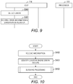
- FIG. 9 illustrates the processing in a case where the device power error is detected.
- the processing of FIG. 8 is described first. Assume that, in FIG. 8 , the IO I/F 114 detects an error (an error other than the device power error) about an IO device 102 . The IO I/F 114 detects an error other than the device power error (Step S 200 ).
- the IO I/F 114 records the occurred error in the error status register 142 (Step S 201 ). Specifically, the IO I/F 114 searches for a row included in the error status register 142 whose the description of error 401 matches the detected error and sets “1” to the error occurrence bit 402 in the retrieved row. At this time, the IO I/F 114 refers the error mask register 143 to obtain the value of the error notification mask bit 502 correspond to the detected error, and determines whether the detected error is the device power error. In this example, the IO I/F 114 determines that the detected error is an error other than the device power error.
- the IO I/F 114 generates an error packet for notifying the error and sends the error packet to the IO I/F 114 itself (Step S 202 ).
- the IO I/F 114 performs pseudo the error packet transmission internally.
- the error packet includes information such as the identification number of the device where the error has occurred, the description of the error, the identification number of the device that has detected the error, and like. For example, in the case where an IO device 102 has detected the error, the error packet includes the identification number assigned to the IO device 102 .
- the IO I/F 114 receives the error packet (Step S 203 ) and records the information on the device where the error occurs in the Root Port error status register 144 (Step S 204 ). Specifically, the IO I/F 114 sets the identification number of the device included in the error packet to the error location number 301 in the Root Port error status register 144 .
- the IO I/F 114 generates an interruption for the processor 111 (Step S 205 ) and issues the interruption to the processor.
- the processor 111 can detect the error and perform processing to address the error.
- the IO device 102 In the case where the IO device 102 itself detects an error about the IO device 102 , the IO device 102 performs Steps S 200 and S 202 .
- the I/O device 402 may also perform Step S 201 .
- Step S 300 the IO I/F 114 detects an error (the device power error) about an IO device 102 .
- the IO I/F 114 detects the device power error (Step S 300 ).
- the IO I/F 114 records the error in the error status register 142 (Step S 301 ). Steps S 300 and S 301 are the same as Steps S 200 and S 201 .
- the IO I/F 114 refers the error mask register 143 to obtain the value of the error notification mask bit 502 correspond to the detected error, and determines whether the detected error is the device power error. In this example, the IO I/F 114 determines that the detected is the device power error. Accordingly, the IO I/F 114 terminates the processing without generating an error packet.
- the IO device 102 may perform Step S 301 .
- the processor 111 does not detect the device power error as an error of the IO device 102 at the time of occurrence thereof.
- the processor 111 detects the device power error by polling the IO I/F 114 for the error status register 142 .
- FIG. 10 is a flowchart of an example of the processing to be performed by the processor 111 of the computer 100 in Embodiment 1 in a case of receiving an interruption.
- Embodiment 1 an interruption is to be made for any error other than the device power error.
- any error other than the device power occurs, there is no possibility that the IO device power supply 103 is stopped. Accordingly, common blocking processing is performed on the IO device 102 to address an error other than the device power error.
- the processor 111 starts error processing. First, the processor 111 reads the value of the Root Port error status register 144 to identify the location where an error occurs (Step S 401 ). The processor 111 performs blocking processing onto the identified location (Step S 402 ) and terminate the processing. The details of the blocking processing will be described with FIG. 12 .
- FIG. 11 is a flowchart of an example of polling processing to be performed by the processor 111 of the computer 100 in Embodiment 1.
- the processor 111 executing the error isolation unit 122 starts the following processing in a case where the computer power supply unit 101 is powered on or the processor 111 receives an instruction from the operator and like.
- the error isolation unit 122 refers to the polling bits 605 included in the monitoring information 130 to identify the devices to be performed polling (Step S 500 ). In this example, assume that only the IO I/F 114 is to be performed polling.
- the error isolation unit 122 performs polling to the determined device (Step S 501 ). Specifically, the error isolation unit 122 reads the values of the link status registers 141 and the error status register 142 held by the IO I/F 114 . If failing in the polling the identified device, the error isolation unit 122 generates an interruption for the processor 111 . In this case, the processor 111 performs processing to address the error.
- the error isolation unit 122 determines whether the device power error occurs based on the read value of the error status register 142 (Step S 502 ). Specifically, the error isolation unit 122 determines whether any row setting a value “1” in the error occurrence bit 402 exists. In a case where there exists a row setting a value “1” in the error occurrence bit 402 , the error isolation unit 122 determines that the device power error occurs.
- the error isolation unit 122 proceeds to Step S 510 .
- the error isolation unit 122 determines whether the device power error is to be isolated (Step S 503 ). Specifically, the error isolation unit 122 performs the following processing.
- the error isolation unit 122 determines whether the occurring device power error is the “Surprise Down Error” based on the value of the error status register 142 . In a case of determining that the occurring device power error is the “Surprise Down Error”, the error isolation unit 122 determines that the occurring device power error is to be isolated.
- the error isolation unit 122 determines whether state of a link connected to the IO device 102 occurring the device power error is state of link down, based on the value of the link status register 141 .
- the error isolation unit 122 determines that the device power error is to be isolated. The foregoing is the description of the processing of Step S 503 .
- the error isolation unit 122 determines whether the device power error is registered in the monitoring information 130 as a valid device power error (Step S 504 ). Specifically, the error isolation unit 122 searches a row corresponding to the device occurring the device power error based on the location name 601 and the location number 602 included in the monitoring information 130 . The error isolation unit 122 determines whether the valid bit 604 included in the retrieved row is set “1”. In a case where the valid bit 604 sets “0”, the error isolation unit 122 does not determine that the device power error is registered in the monitoring information 130 as a valid device power error.
- the error isolation unit 122 registers the device power error to the monitoring information 130 (Step S 505 ). Subsequently the error isolation unit 122 proceeds to Step S 510 . Specifically, the error isolation unit 122 sets “1” to the valid bit 604 included in the row retrieved at Step S 504 . The error isolation unit 122 further obtains the current time from the timer 113 and sets the obtained time to the error occurrence time 603 .
- the error isolation unit 122 determines whether a certain time has elapsed after the occurrence of the device power error (Step S 506 ). Specifically, the error isolation unit 122 performs the following processing.
- the error isolation unit 122 obtains the current time from the timer 113 .
- the error isolation unit 122 also obtains the time of the error occurrence time 603 included in the row retrieved at Step S 504 .
- the error isolation unit 122 calculates the time that has elapsed after the occurrence of the error, using the current time and the time obtained from the error occurrence time 603 .
- the error isolation unit 122 determines whether the calculated time is longer than a predetermined period.
- the predetermined period can be changed by the operator as appropriate. In a case where the calculated time is longer than the predetermined period, the error isolation unit 122 determines that a certain time has elapsed after the occurrence of the error.
- the error isolation unit 122 proceeds to Step S 510 without detecting the device power error as an error of the IO device 102 .
- the error isolation unit 122 clears the information on the device power error registered in the monitoring information 130 (Step S 507 ). Specifically, the error isolation unit 122 sets “0” to the error occurrence time 603 and the valid bit 604 in the row retrieved at Step S 504 . In this case, the error isolation unit 122 detects the device power error as an error of the IO device 102 .
- Step S 508 the error isolation unit 122 performs blocking processing.
- the details of the blocking processing will be described with FIG. 12 .
- the error isolation unit 122 clears the information on the error (Step S 509 ) and thereafter, proceeds to Step S 510 .
- the error isolation unit 122 clears the values set to the Root Port error status register 144 and the error status register 142 held by the IO I/F 114 .
- Step S 510 the error isolation unit 122 stands by for a certain period (Step S 510 ). After elapse of a certain period, the error isolation unit 122 returns to Step S 501 and repeats the same processing.
- the error isolation unit 122 does not detect the error as an error of the IO device 102 , but detects as a link-down error in the protocol level.
- the error isolation unit 122 clears the information on the device power error registered in the monitoring information 130 (Step S 511 ).
- the processing at Step S 511 is the same as the processing at Step S 507 .
- Step S 512 the error isolation unit 122 performs link down processing for protocol.
- the details of the link down processing for protocol will be described later with FIG. 13 .
- the error isolation unit 122 clears the information on the error (Step S 509 ) and thereafter proceeds to Step S 510 .
- the blocking processing and the link down processing for protocol may be performed by the IO device driver 121 .
- the error isolation unit 122 instructs the IO device driver 121 to execute the processings.
- the error isolation, unit 122 in a case of detecting the device power error, determines whether the device power error is to be isolated by polling. In a case where the device power error is not to be isolated, the error isolation unit 122 performs polling again after elapse of a certain period and determines whether the device power error is an error to be isolated based on the result of the polling.
- the reason why the polling is performed for multiple times is that, in a case where the link is disconnected because of an error in the IO device 102 , it takes time to detect the disconnection of the link and update the value of the link status register 141 . Updating the value of the “Surprise Down Error” in the error status register 142 also takes time.
- the computer 100 detects the error in the IO device 102 sooner than this time.
- the error isolation unit 122 cannot isolate the error caused by the stop of the IO device power supply unit 103 . For this reason, considering the time taken to update the value of the link status register 141 or the error status register 142 , the error isolation unit 122 performs polling again when a certain time has elapsed after detection of the device power error to determine whether to isolate the device power error based on the result of the polling. Such control achieves correct isolation of the occurring device power error.
- the occurring device power error is an error caused by stop of the IO device power supply unit 103 . Accordingly, the error isolation unit 122 detects the device power error as a link-down error in the protocol level. In other words, the device power error is not treated as an error in the IO device 102 (hardware).
- the computer 100 In a case where an error comparable to the stop of the IO device power supply unit 103 occurs together with an error in the IO device 102 , the computer 100 first performs link down processing for protocol. However, the error will not be eliminated. The computer 100 accepts a blocking request from the IO device 102 . The details of the processing in response to a blocking request from the IO device 102 will be described later with FIG. 14 .
- FIG. 12 is a flowchart of an example of the blocking processing to be performed by the OS 120 in Embodiment 1.
- the OS 120 performs link disconnection processing for protocol (Step S 600 ).
- the link disconnection processing for protocol is performed in accordance with the protocol such as Fibre Channel or Ethernet.
- the link disconnection processing for protocol is a well known processing; the explanation thereof is omitted here.
- the OS 120 clears the memory 112 (Step S 601 ). For example, the OS 120 clears a storage area of the memory 112 used for queues to issue IOs to the external device through the IO device 102 .
- the OS 120 updates the monitoring information 130 (Step S 602 ). Specifically, the error isolation unit 122 changes the value of the polling bit 605 of the row corresponding to the device occurring the error included in the monitoring information 130 to “0”. This operation reduces the number of devices to be performed polling and therefore, the load to the processor 111 caused by polling can be reduced.
- the OS 120 updates the hardware status information stored in the memory 112 (Step S 603 ). Specifically, the OS 120 changes the status of the IO device 102 in the hardware status information held by the IO device driver 121 to the status of blocked. As a result, the computer 100 is controlled not to access the IO device 102 .
- the OS 120 performs block processing of the hard register (Step S 604 ) and terminates the processing.
- the OS 120 sets “1” to the error notification mask bits 502 in all rows of the error mask register 143 held by the IO I/F 114 , and clears the values of the error status register 142 and the Root Port error status register 144 .
- the OS 120 further performs link disconnection processing.
- FIG. 13 is a flowchart of an example of the link down processing for protocol to be performed by the OS 120 in Embodiment 1.
- Step S 700 The OS performs link disconnection processing for protocol (Step S 700 ) and clears the memory 112 (Step S 701 ). Thereafter, the OS 120 terminates the processing.
- Step S 700 is the same as Step S 602 .
- Step S 701 is the same as Step S 603 .
- the OS 120 can re-establish a link between the computer 100 and the IO device 102 .
- FIG. 14 is a flowchart of an example of processing to be performed by the OS 120 in Embodiment 1 in a case of receiving a blocking request from an IO device 102 .
- the OS 120 receives a blocking request from an IO device 102 (Step S 800 ).
- the OS 120 receives the blocking request from the IO device 102 via the redundant path 105 .
- the OS 120 performs processing to block the IO device 102 that has sent the blocking request (Step S 801 ) and terminates the processing.
- the processing to block the IO device 102 is the same as the blocking processing in FIG. 12 .
- Embodiment 1 a mask is set for the error that occurs in a case where the IO device power supply unit 103 stops. Accordingly, the error is not detected as an error of the IO device 102 in a case where such error occurs. Because the computer 100 detects the masked error by polling, and performs polling for a plurality of times, so it can correctly isolate the error caused the stop of the IO device power supply unit 103 from the other errors.
- Embodiment 2 The computer system in Embodiment 2 is different from the one in Embodiment 1 in the point where the computer 100 is connected with the IO device 102 via a switch 106 .
- the computer 100 , the IO device 102 , the computer power supply unit 101 , and the IO device power supply unit 103 are the same as those in Embodiment 1 and therefore, the descriptions thereof are omitted herein.
- the switch 106 is an apparatus for relaying data transmitted and received between apparatuses.
- the computer 100 and the switch 106 are connected by a main path 104 and a redundant path 105 ; the switch 106 and the IO devices 102 are connected by a main path 107 and a redundant path 108 .
- the switch 106 includes at least one uplink port 115 and at least one downlink port 116 .
- the switch 106 further includes not shown hardware such as a processor, a memory, and like.
- the uplink port 115 is a port for connecting to a host apparatus. In this embodiment, at least one uplink port 115 is connected with the IO I/F 114 of the computer 100 .
- the downlink port 115 is the port other than the uplink port 115 among the ports included in the switch 106 . In this embodiment, at least one downlink port 116 is connected with the IO device 102 .
- Each downlink port 116 includes a link status register 151 , an error status register 152 , and an error mask register 153 .
- the link status register 151 , the error status register 152 , and the error mask register 153 are the same as the link status register 141 , the error status register 142 , and the error mask register 143 , respectively.
- the initialization processing in Embodiment 2 is partially different from the initialization processing in Embodiment 1. Specifically, at Step S 101 , the error isolation unit 122 clears the values of the error status register 142 and the error status register 152 . At Step S 103 , the error isolation unit 122 initializes the error mask register 143 and the error mask register 153 . The rest of the processing is the same as the processing in Embodiment 1 and therefore the description thereof is omitted herein.
- FIGS. 16 and 17 are sequence diagrams for illustrating the processing to be performed in a case where an error is detected in the computer system in Embodiment 2.
- FIG. 16 illustrates the processing in a case where an error other than a device power error is detected.
- FIG. 17 illustrates the processing in a case where the device power error is detected.
- the processing of FIG. 16 is described first.
- the downlink port 116 of the switch 106 detects an error (an error other than the device power error) about the IO device 102 (Step S 900 ).
- Step S 901 The downlink port 116 records the occurred error in the error status register 152 (Step S 901 ).
- Step S 901 is the same as Step S 201 . If the error is detected by the uplink port 115 of the switch 106 , the uplink port 115 can perform the same processing.
- the switch 106 generates an error packet for notifying the error and sends the error packet to the IO I/F 114 (Step S 902 ).
- the error packet includes information such as the identification number of the device where the error has occurred, the description of the error, the identification number of the device that has detected the error, and like. For example, in the case where the downlink port 116 has detected the error, the error packet includes the identification number assigned to the downlink port 116 .
- Steps S 903 to S 905 are the same as Steps S 203 to S 905 and therefore, the description thereof is omitted herein.
- the downlink port 116 of the switch 106 detects an error (the device power error) about the IO device 102 (Step S 1000 ).
- the downlink port 116 of the switch 106 records the error in the error status register 152 (Step S 1001 ).
- Steps S 1000 and S 1001 are the same as Steps S 900 and S 901 .
- the switch 106 determines that the detected error is the device power error based on the error mask register 153 . Accordingly, the switch 106 terminates the processing without generating an error packet.
- the processor 111 detects the device power error by polling the error status register 142 held by the IO I/F 114 and the error status register 152 held by the downlink port 116 .
- the processing to be performed by the processor 111 in a case of receiving an interruption is the same as the processing in Embodiment 1 and therefore, the description is omitted herein.
- the polling processing to be performed by the processor 111 of the computer 100 in Embodiment 2 is partially different. Specifically, at Step S 501 , the error isolation unit 122 performs polling to the IO I/F 114 and the downlink port 116 of the switch 106 . The rest of the processing is the same as the processing in Embodiment 1 and therefore, the description is omitted herein.
- Embodiment 2 has the same effects as Embodiment 1, even though the computer 100 is connected with the IO device 102 via the switch 106 .
- the present invention is not limited to the above embodiment and includes various modification examples.
- the configurations of the above embodiment are described in detail so as to describe the present invention comprehensibly.
- the present invention is not necessarily limited to the embodiment that is provided with all of the configurations described.
- a part of each configuration of the embodiment may be removed, substituted, or added to other configurations.
- a part or the entirety of each of the above configurations, functions, processing units, processing means, and the like may be realized by hardware, such as by designing integrated circuits therefor.
- the present invention can be realized by program codes of software that realizes the functions of the embodiment.
- a storage medium on which the program codes are recorded is provided to a computer, and a CPU that the computer is provided with reads the program codes stored on the storage medium.
- the program codes read from the storage medium realize the functions of the above embodiment, and the program codes and the storage medium storing the program codes constitute the present invention.
- Examples of such a storage medium used for supplying program codes include a flexible disk, a CD-ROM, a DVD-ROM, a hard disk, a solid state drive (SSD), an optical disc, a magneto-optical disc, a CD-R, a magnetic tape, a non-volatile memory card, and a ROM.
- SSD solid state drive
- the program codes that realize the functions written in the present embodiment can be implemented by a wide range of programming and scripting languages such as assembler, C/C++, Perl, shell scripts, PHP, and Java (registered trademark).
- the program codes of the software that realizes the functions of the embodiment are stored on storing means such as a hard disk or a memory of the computer or on a storage medium such as a CD-RW or a CD-R by distributing the program codes through a network and that the CPU that the computer is provided with reads and executes the program codes stored on the storing means or on the storage medium.
- control lines and information lines that are considered as necessary for description are illustrated, and all the control lines and information lines of a product are not necessarily illustrated. All of the configurations of the embodiment may be connected to each other.
Landscapes
- Engineering & Computer Science (AREA)
- Theoretical Computer Science (AREA)
- General Engineering & Computer Science (AREA)
- Physics & Mathematics (AREA)
- General Physics & Mathematics (AREA)
- Quality & Reliability (AREA)
- Computing Systems (AREA)
- Computer Hardware Design (AREA)
- Mathematical Physics (AREA)
- Health & Medical Sciences (AREA)
- Biomedical Technology (AREA)
- Debugging And Monitoring (AREA)
Abstract
Description
Claims (10)
Applications Claiming Priority (1)
| Application Number | Priority Date | Filing Date | Title |
|---|---|---|---|
| PCT/JP2015/069626 WO2017006457A1 (en) | 2015-07-08 | 2015-07-08 | Computer system and fault isolation method |
Publications (2)
| Publication Number | Publication Date |
|---|---|
| US20180189126A1 US20180189126A1 (en) | 2018-07-05 |
| US10599510B2 true US10599510B2 (en) | 2020-03-24 |
Family
ID=57686204
Family Applications (1)
| Application Number | Title | Priority Date | Filing Date |
|---|---|---|---|
| US15/740,078 Active 2036-02-12 US10599510B2 (en) | 2015-07-08 | 2015-07-08 | Computer system and error isolation method |
Country Status (2)
| Country | Link |
|---|---|
| US (1) | US10599510B2 (en) |
| WO (1) | WO2017006457A1 (en) |
Families Citing this family (5)
| Publication number | Priority date | Publication date | Assignee | Title |
|---|---|---|---|---|
| CN110377136A (en) * | 2019-06-18 | 2019-10-25 | 苏州浪潮智能科技有限公司 | A kind of PSU original value log recording method and device |
| CN115080284B (en) * | 2021-03-12 | 2026-02-03 | 腾讯科技(深圳)有限公司 | Fault handling methods, devices and electronic equipment for business systems |
| CN114356811B (en) * | 2022-03-17 | 2022-06-07 | 苏州浪潮智能科技有限公司 | Communication link updating method, device and related equipment |
| US12321217B2 (en) * | 2023-02-22 | 2025-06-03 | Dell Products, L.P. | Method and apparatus for monitoring a PCIe NTB |
| CN118885359B (en) * | 2024-09-27 | 2024-12-27 | 苏州元脑智能科技有限公司 | Extension equipment state detection method, server and electronic equipment |
Citations (22)
| Publication number | Priority date | Publication date | Assignee | Title |
|---|---|---|---|---|
| US5680537A (en) * | 1995-03-01 | 1997-10-21 | Unisys Corporation | Method and apparatus for isolating an error within a computer system that transfers data via an interface device |
| US5931958A (en) * | 1997-04-11 | 1999-08-03 | Dell Usa, L.P. | Processor controlled link resiliency circuit for serial storage architectures |
| US20020184576A1 (en) * | 2001-03-29 | 2002-12-05 | International Business Machines Corporation | Method and apparatus for isolating failing hardware in a PCI recoverable error |
| US6728216B1 (en) * | 1998-02-27 | 2004-04-27 | Advanced Micro Devices, Inc. | Arrangement in a network repeater for monitoring link integrity and selectively down shifting link speed based on local configuration signals |
| US20060104209A1 (en) * | 2004-11-18 | 2006-05-18 | De Araujo Daniel F | Failure isolation in a communication system |
| US20070286385A1 (en) * | 2003-10-14 | 2007-12-13 | Varble T B | Communications device and method of operating a communications device that continues to connect local users after a link fails |
| US20080228941A1 (en) * | 2003-11-06 | 2008-09-18 | Petre Popescu | Ethernet Link Monitoring Channel |
| US20090248947A1 (en) * | 2008-03-25 | 2009-10-01 | Aprius Inc. | PCI-Express Function Proxy |
| US20100074264A1 (en) * | 2008-09-25 | 2010-03-25 | Kimberly Davis | Method and apparatus to facilitate system to system protocol exchange in back to back non-transparent bridges |
| US20110246833A1 (en) * | 2008-12-15 | 2011-10-06 | Bockhaus John W | Detecting An Unreliable Link In A Computer System |
| US8140922B2 (en) | 2008-05-20 | 2012-03-20 | International Business Machines Corporation | Method for correlating an error message from a PCI express endpoint |
| US20120294606A1 (en) * | 2009-08-31 | 2012-11-22 | Gary Michael Miller | System and method for enhancement of ethernet link loss forwarding |
| US8510592B1 (en) * | 2009-09-15 | 2013-08-13 | Netapp, Inc. | PCI error resilience |
| US20130246855A1 (en) * | 2010-11-12 | 2013-09-19 | Fujitsu Limited | Error Location Specification Method, Error Location Specification Apparatus and Computer-Readable Recording Medium in Which Error Location Specification Program is Recorded |
| US20140006670A1 (en) * | 2012-06-27 | 2014-01-02 | Mahesh Wagh | Controlling A Physical Link Of A First Protocol Using An Extended Capability Structure Of A Second Protocol |
| US20140115359A1 (en) * | 2011-06-08 | 2014-04-24 | Nec Corporation | Computer system, connection device, power supply control method, and power supply control program recording medium |
| US20140189427A1 (en) * | 2012-12-28 | 2014-07-03 | Prahladachar Jayaprakash Bharadwaj | Live error recovery |
| US20150032405A1 (en) * | 2013-07-29 | 2015-01-29 | Huawei Technologies Co., Ltd. | Method and Apparatus for Detecting Interface Connection Between Devices |
| US20150089332A1 (en) * | 2013-09-26 | 2015-03-26 | International Business Machines Corporation | Error detection and isolation |
| US20150281126A1 (en) * | 2014-03-31 | 2015-10-01 | Plx Technology, Inc. | METHODS AND APPARATUS FOR A HIGH PERFORMANCE MESSAGING ENGINE INTEGRATED WITHIN A PCIe SWITCH |
| US20150370683A1 (en) * | 2014-06-19 | 2015-12-24 | Fujitsu Limited | Apparatus and method for identifying a cause of an error occurring in a network connecting devices within an information processing apparatus |
| US20180131573A1 (en) * | 2016-11-08 | 2018-05-10 | Canon Kabushiki Kaisha | Management system and control method |
Family Cites Families (1)
| Publication number | Priority date | Publication date | Assignee | Title |
|---|---|---|---|---|
| WO2014115257A1 (en) * | 2013-01-23 | 2014-07-31 | 株式会社 日立製作所 | Storage device employing pci-express connection solid-state drive |
-
2015
- 2015-07-08 WO PCT/JP2015/069626 patent/WO2017006457A1/en not_active Ceased
- 2015-07-08 US US15/740,078 patent/US10599510B2/en active Active
Patent Citations (22)
| Publication number | Priority date | Publication date | Assignee | Title |
|---|---|---|---|---|
| US5680537A (en) * | 1995-03-01 | 1997-10-21 | Unisys Corporation | Method and apparatus for isolating an error within a computer system that transfers data via an interface device |
| US5931958A (en) * | 1997-04-11 | 1999-08-03 | Dell Usa, L.P. | Processor controlled link resiliency circuit for serial storage architectures |
| US6728216B1 (en) * | 1998-02-27 | 2004-04-27 | Advanced Micro Devices, Inc. | Arrangement in a network repeater for monitoring link integrity and selectively down shifting link speed based on local configuration signals |
| US20020184576A1 (en) * | 2001-03-29 | 2002-12-05 | International Business Machines Corporation | Method and apparatus for isolating failing hardware in a PCI recoverable error |
| US20070286385A1 (en) * | 2003-10-14 | 2007-12-13 | Varble T B | Communications device and method of operating a communications device that continues to connect local users after a link fails |
| US20080228941A1 (en) * | 2003-11-06 | 2008-09-18 | Petre Popescu | Ethernet Link Monitoring Channel |
| US20060104209A1 (en) * | 2004-11-18 | 2006-05-18 | De Araujo Daniel F | Failure isolation in a communication system |
| US20090248947A1 (en) * | 2008-03-25 | 2009-10-01 | Aprius Inc. | PCI-Express Function Proxy |
| US8140922B2 (en) | 2008-05-20 | 2012-03-20 | International Business Machines Corporation | Method for correlating an error message from a PCI express endpoint |
| US20100074264A1 (en) * | 2008-09-25 | 2010-03-25 | Kimberly Davis | Method and apparatus to facilitate system to system protocol exchange in back to back non-transparent bridges |
| US20110246833A1 (en) * | 2008-12-15 | 2011-10-06 | Bockhaus John W | Detecting An Unreliable Link In A Computer System |
| US20120294606A1 (en) * | 2009-08-31 | 2012-11-22 | Gary Michael Miller | System and method for enhancement of ethernet link loss forwarding |
| US8510592B1 (en) * | 2009-09-15 | 2013-08-13 | Netapp, Inc. | PCI error resilience |
| US20130246855A1 (en) * | 2010-11-12 | 2013-09-19 | Fujitsu Limited | Error Location Specification Method, Error Location Specification Apparatus and Computer-Readable Recording Medium in Which Error Location Specification Program is Recorded |
| US20140115359A1 (en) * | 2011-06-08 | 2014-04-24 | Nec Corporation | Computer system, connection device, power supply control method, and power supply control program recording medium |
| US20140006670A1 (en) * | 2012-06-27 | 2014-01-02 | Mahesh Wagh | Controlling A Physical Link Of A First Protocol Using An Extended Capability Structure Of A Second Protocol |
| US20140189427A1 (en) * | 2012-12-28 | 2014-07-03 | Prahladachar Jayaprakash Bharadwaj | Live error recovery |
| US20150032405A1 (en) * | 2013-07-29 | 2015-01-29 | Huawei Technologies Co., Ltd. | Method and Apparatus for Detecting Interface Connection Between Devices |
| US20150089332A1 (en) * | 2013-09-26 | 2015-03-26 | International Business Machines Corporation | Error detection and isolation |
| US20150281126A1 (en) * | 2014-03-31 | 2015-10-01 | Plx Technology, Inc. | METHODS AND APPARATUS FOR A HIGH PERFORMANCE MESSAGING ENGINE INTEGRATED WITHIN A PCIe SWITCH |
| US20150370683A1 (en) * | 2014-06-19 | 2015-12-24 | Fujitsu Limited | Apparatus and method for identifying a cause of an error occurring in a network connecting devices within an information processing apparatus |
| US20180131573A1 (en) * | 2016-11-08 | 2018-05-10 | Canon Kabushiki Kaisha | Management system and control method |
Also Published As
| Publication number | Publication date |
|---|---|
| WO2017006457A1 (en) | 2017-01-12 |
| US20180189126A1 (en) | 2018-07-05 |
Similar Documents
| Publication | Publication Date | Title |
|---|---|---|
| TWI734890B (en) | System and method for providing data replication in nvme-of ethernet ssd | |
| US10027532B2 (en) | Storage control apparatus and storage control method | |
| US10599510B2 (en) | Computer system and error isolation method | |
| US7904744B2 (en) | Data storage using multiple protocols | |
| CN110535692B (en) | Fault handling method, device, computer equipment, storage medium and storage system | |
| JP6379905B2 (en) | Control device and control method | |
| EP3429128B1 (en) | Hard drive operation method and hard drive manager | |
| US12519740B2 (en) | Method to reset switch when controller fault is detected | |
| CN106502814B (en) | Method and device for recording error information of PCIE (peripheral component interface express) equipment | |
| US20140298076A1 (en) | Processing apparatus, recording medium storing processing program, and processing method | |
| US11914725B2 (en) | Operating system agnostic and secure bi-directional data handling | |
| JP5689783B2 (en) | Computer, computer system, and failure information management method | |
| KR102018225B1 (en) | Connection Method | |
| US9454452B2 (en) | Information processing apparatus and method for monitoring device by use of first and second communication protocols | |
| US9246848B2 (en) | Relay apparatus, storage system, and method of controlling relay apparatus | |
| JP6357879B2 (en) | System and fault handling method | |
| US8775695B2 (en) | Specific identification information management device, information processing device, and specific identification information setting method | |
| CN119025448A (en) | Storage device and storage controller control method | |
| CN118051366A (en) | Fault handling method and computing equipment | |
| US11463542B2 (en) | Server and method of replacing a server in a network | |
| WO2019169582A1 (en) | Method and device for processing interrupt | |
| WO2021159897A1 (en) | Fault notification method and related device | |
| US20160366024A1 (en) | Method and associated apparatus for managing a storage system | |
| WO2026037009A1 (en) | Bandwidth allocation method, server, device, medium and program product | |
| US10409660B2 (en) | Storage system and control method therefor |
Legal Events
| Date | Code | Title | Description |
|---|---|---|---|
| AS | Assignment |
Owner name: HITACHI, LTD., JAPAN Free format text: ASSIGNMENT OF ASSIGNORS INTEREST;ASSIGNORS:SUGIMOTO, KEN;FUNAYA, YUSUKE;SIGNING DATES FROM 20171204 TO 20171206;REEL/FRAME:044489/0729 |
|
| FEPP | Fee payment procedure |
Free format text: ENTITY STATUS SET TO UNDISCOUNTED (ORIGINAL EVENT CODE: BIG.); ENTITY STATUS OF PATENT OWNER: LARGE ENTITY |
|
| STPP | Information on status: patent application and granting procedure in general |
Free format text: DOCKETED NEW CASE - READY FOR EXAMINATION |
|
| STPP | Information on status: patent application and granting procedure in general |
Free format text: NON FINAL ACTION MAILED |
|
| STPP | Information on status: patent application and granting procedure in general |
Free format text: RESPONSE TO NON-FINAL OFFICE ACTION ENTERED AND FORWARDED TO EXAMINER |
|
| STPP | Information on status: patent application and granting procedure in general |
Free format text: NOTICE OF ALLOWANCE MAILED -- APPLICATION RECEIVED IN OFFICE OF PUBLICATIONS |
|
| STPP | Information on status: patent application and granting procedure in general |
Free format text: PUBLICATIONS -- ISSUE FEE PAYMENT VERIFIED |
|
| STCF | Information on status: patent grant |
Free format text: PATENTED CASE |
|
| MAFP | Maintenance fee payment |
Free format text: PAYMENT OF MAINTENANCE FEE, 4TH YEAR, LARGE ENTITY (ORIGINAL EVENT CODE: M1551); ENTITY STATUS OF PATENT OWNER: LARGE ENTITY Year of fee payment: 4 |
|
| AS | Assignment |
Owner name: HITACHI VANTARA, LTD., JAPAN Free format text: COMPANY SPLIT;ASSIGNOR:HITACHI, LTD.;REEL/FRAME:069518/0761 Effective date: 20240401 |