US10598083B2 - Turbine for an exhaust turbocharger - Google Patents
Turbine for an exhaust turbocharger Download PDFInfo
- Publication number
- US10598083B2 US10598083B2 US15/928,894 US201815928894A US10598083B2 US 10598083 B2 US10598083 B2 US 10598083B2 US 201815928894 A US201815928894 A US 201815928894A US 10598083 B2 US10598083 B2 US 10598083B2
- Authority
- US
- United States
- Prior art keywords
- flow
- turbine
- flow duct
- closure element
- ducts
- Prior art date
- Legal status (The legal status is an assumption and is not a legal conclusion. Google has not performed a legal analysis and makes no representation as to the accuracy of the status listed.)
- Active, expires
Links
Images


Classifications
-
- F—MECHANICAL ENGINEERING; LIGHTING; HEATING; WEAPONS; BLASTING
- F02—COMBUSTION ENGINES; HOT-GAS OR COMBUSTION-PRODUCT ENGINE PLANTS
- F02B—INTERNAL-COMBUSTION PISTON ENGINES; COMBUSTION ENGINES IN GENERAL
- F02B37/00—Engines characterised by provision of pumps driven at least for part of the time by exhaust
- F02B37/12—Control of the pumps
- F02B37/22—Control of the pumps by varying cross-section of exhaust passages or air passages, e.g. by throttling turbine inlets or outlets or by varying effective number of guide conduits
-
- F—MECHANICAL ENGINEERING; LIGHTING; HEATING; WEAPONS; BLASTING
- F01—MACHINES OR ENGINES IN GENERAL; ENGINE PLANTS IN GENERAL; STEAM ENGINES
- F01D—NON-POSITIVE DISPLACEMENT MACHINES OR ENGINES, e.g. STEAM TURBINES
- F01D17/00—Regulating or controlling by varying flow
- F01D17/10—Final actuators
- F01D17/12—Final actuators arranged in stator parts
- F01D17/14—Final actuators arranged in stator parts varying effective cross-sectional area of nozzles or guide conduits
- F01D17/148—Final actuators arranged in stator parts varying effective cross-sectional area of nozzles or guide conduits by means of rotatable members, e.g. butterfly valves
-
- F—MECHANICAL ENGINEERING; LIGHTING; HEATING; WEAPONS; BLASTING
- F02—COMBUSTION ENGINES; HOT-GAS OR COMBUSTION-PRODUCT ENGINE PLANTS
- F02B—INTERNAL-COMBUSTION PISTON ENGINES; COMBUSTION ENGINES IN GENERAL
- F02B37/00—Engines characterised by provision of pumps driven at least for part of the time by exhaust
- F02B37/02—Gas passages between engine outlet and pump drive, e.g. reservoirs
- F02B37/025—Multiple scrolls or multiple gas passages guiding the gas to the pump drive
-
- F—MECHANICAL ENGINEERING; LIGHTING; HEATING; WEAPONS; BLASTING
- F02—COMBUSTION ENGINES; HOT-GAS OR COMBUSTION-PRODUCT ENGINE PLANTS
- F02B—INTERNAL-COMBUSTION PISTON ENGINES; COMBUSTION ENGINES IN GENERAL
- F02B37/00—Engines characterised by provision of pumps driven at least for part of the time by exhaust
- F02B37/12—Control of the pumps
- F02B37/18—Control of the pumps by bypassing exhaust from the inlet to the outlet of turbine or to the atmosphere
- F02B37/183—Arrangements of bypass valves or actuators therefor
-
- F—MECHANICAL ENGINEERING; LIGHTING; HEATING; WEAPONS; BLASTING
- F02—COMBUSTION ENGINES; HOT-GAS OR COMBUSTION-PRODUCT ENGINE PLANTS
- F02C—GAS-TURBINE PLANTS; AIR INTAKES FOR JET-PROPULSION PLANTS; CONTROLLING FUEL SUPPLY IN AIR-BREATHING JET-PROPULSION PLANTS
- F02C6/00—Plural gas-turbine plants; Combinations of gas-turbine plants with other apparatus; Adaptations of gas-turbine plants for special use
- F02C6/04—Gas-turbine plants providing heated or pressurised working fluid for other apparatus, e.g. without mechanical power output
- F02C6/10—Gas-turbine plants providing heated or pressurised working fluid for other apparatus, e.g. without mechanical power output supplying working fluid to a user, e.g. a chemical process, which returns working fluid to a turbine of the plant
- F02C6/12—Turbochargers, i.e. plants for augmenting mechanical power output of internal-combustion piston engines by increase of charge pressure
-
- F—MECHANICAL ENGINEERING; LIGHTING; HEATING; WEAPONS; BLASTING
- F05—INDEXING SCHEMES RELATING TO ENGINES OR PUMPS IN VARIOUS SUBCLASSES OF CLASSES F01-F04
- F05D—INDEXING SCHEME FOR ASPECTS RELATING TO NON-POSITIVE-DISPLACEMENT MACHINES OR ENGINES, GAS-TURBINES OR JET-PROPULSION PLANTS
- F05D2220/00—Application
- F05D2220/40—Application in turbochargers
-
- Y—GENERAL TAGGING OF NEW TECHNOLOGICAL DEVELOPMENTS; GENERAL TAGGING OF CROSS-SECTIONAL TECHNOLOGIES SPANNING OVER SEVERAL SECTIONS OF THE IPC; TECHNICAL SUBJECTS COVERED BY FORMER USPC CROSS-REFERENCE ART COLLECTIONS [XRACs] AND DIGESTS
- Y02—TECHNOLOGIES OR APPLICATIONS FOR MITIGATION OR ADAPTATION AGAINST CLIMATE CHANGE
- Y02T—CLIMATE CHANGE MITIGATION TECHNOLOGIES RELATED TO TRANSPORTATION
- Y02T10/00—Road transport of goods or passengers
- Y02T10/10—Internal combustion engine [ICE] based vehicles
- Y02T10/12—Improving ICE efficiencies
-
- Y02T10/144—
Definitions
- the invention relates to a turbine for an exhaust gas turbocharger, which has a turbine housing in which are provided a first and a second flow duct that each have an inlet region and an outlet region.
- a turbine for an exhaust gas turbocharger is known from DE 10 2010 008 411 A1.
- This turbine has a turbine housing containing a turbine wheel that can be acted upon by an exhaust gas from an internal combustion engine and having at least two channels which are fluidically separated from one another at least in certain regions and through which the exhaust gas can flow.
- At least one adjustable valve is also provided. This valve has a closing position that closes a bypass duct and an open position which at least partially opens the bypass duct. This valve allows at least part of the exhaust gas to bypass the turbine wheel.
- the at least two channels are fluidically at least partially separated from one another by the valve in a separating region.
- valve has at least one intermediate position in which the bypass duct is closed and the at least two channels are fluidically connected to one another in the separating region.
- This valve is an axial slide valve or a rotary slide valve which must be actuated, using an actuator, against the pressure exerted by the exhaust gas. Furthermore, in this approach the adjustability of the valve is limited.
- An object of the invention is to specify a turbine for an exhaust gas turbocharger which does not have the above-mentioned drawbacks.
- Example embodiments of the present invention provide a turbine for an exhaust gas turbocharger, which has a turbine housing in which are provided a first and a second flow duct that each has an inlet region and an outlet region, wherein a self-regulating rotary slide valve, which has an adjustable flow duct closure element, is arranged in the inlet region of the flow ducts.
- the advantages of the invention are that, when during operation of the exhaust gas turbocharger, a pressure difference arises between the two flow ducts, the flow duct closure element the flow closure element is automatically adjusted as a consequence of this pressure difference.
- This automatic adjustment takes place such that the connecting region between the two flow ducts is opened so that exhaust gas from the flow duct having the higher pressure is routed into the flow duct having the lower pressure.
- the degree of opening between the two flow ducts is dependent on the prevailing pressure difference. If this pressure difference is greater than a defined pressure difference threshold value, then the transition region between the two flow ducts is fully opened.
- This self-regulating opening of the flow duct closure element of the rotary slide valve in dependence on a pressure difference existing between the flow ducts, achieves a possibility for connection between the two flow ducts provided in the turbine housing that is simple, cost-effective, space-saving and favorable to flow.
- FIG. 1 is a block diagram illustrating the basic construction of an exhaust gas turbocharger
- FIG. 2 is a first perspective diagram illustrating a first example embodiment for a turbine having a self-regulating rotary slide valve
- FIG. 3 is a second perspective diagram illustrating the first example embodiment for a turbine having a self-regulating rotary slide valve
- FIG. 4 is a third perspective diagram illustrating the first example embodiment for a turbine having a self-regulating rotary slide valve
- FIG. 5 is a fourth perspective diagram illustrating the first example embodiment for a turbine having a self-regulating rotary slide valve
- FIG. 6 is a first perspective diagram illustrating a second example embodiment for a turbine having a self-regulating rotary slide valve
- FIG. 7 is a second perspective diagram illustrating the second example embodiment for a turbine having a self-regulating rotary slide valve
- FIG. 8 is a third perspective diagram illustrating the second example embodiment for a turbine having a self-regulating rotary slide valve.
- FIG. 1 is a block diagram illustrating the basic construction of an exhaust gas turbocharger 1 .
- This exhaust gas turbocharger 1 has a turbine 2 which contains a turbine wheel 4 arranged in a turbine housing 3 .
- the exhaust gas turbocharger 1 also has a compressor 5 which contains a compressor wheel 7 arranged in a compressor housing 6 .
- the exhaust gas turbocharger 1 also has a bearing device 9 which contains a bearing housing 10 that is connected to the compressor housing 6 and the turbine housing 3 .
- a shaft 8 at one end region of which there is the turbine wheel 4 and at the other end region there is the compressor wheel 7 , is mounted in the bearing housing 10 .
- the turbine wheel 4 and the compressor wheel 7 may be secured to the shaft 8 or be an integral constituent of the shaft 8 .
- an exhaust gas stream of a motor vehicle supplied to the exhaust gas turbocharger, drives the turbine wheel 4 , thus turning the shaft 8 which is fixedly connected to the turbine wheel 4 .
- This rotational movement is transferred to the compressor wheel 7 , which is also fixedly connected to the shaft 8 .
- Fresh air supplied to the compressor 5 is compressed by means of the compressor wheel 7 ; this air is supplied, together with the necessary fuel, to the combustion chambers of the engine of the motor vehicle in order to increase engine power.
- the turbine housing 3 has two mutually parallel flow ducts, as are used for example in so-called twin-scroll exhaust gas turbochargers.
- twin-scroll exhaust gas turbochargers When using a two-channel exhaust gas manifold of the internal combustion engine, this permits separate conveying of the exhaust gases to the turbine wheel.
- the advantage of this measure is that a mutual negative influence on the individual cylinders during a charge exchange is avoided.
- the exhaust gas ducts from, for example, two cylinders in the case of four-cylinder engines are combined into one exhaust gas stream, conveyed via respectively one of the flow ducts and re-combined shortly before the turbine wheel.
- This approach has the result that the exhaust gas back-pressure is reduced and the gas exchange of the internal combustion engine is improved, which in turn leads to lower consumption, increased power and an improvement in the response behavior of the internal combustion engine.
- the two flow ducts are coupled to one another in their inlet region, using a self-regulating rotary slide valve which has a flow duct closure element.
- the two flow ducts may be fully decoupled from one another, fully connected to one another or partially connected to one another.
- the basic setting of the flow duct closure element is such that the two flow ducts are fully decoupled from one another. This basic setting is brought about by using a setting device which has, inter alia, two preloaded spring elements.
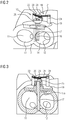
- FIG. 2 is a first perspective diagram illustrating a first example embodiment for a turbine having a self-regulating rotary slide valve.
- the figure shows the inlet region of the turbine housing 3 of this turbine 2 , in which the exhaust gas from the internal combustion engine is introduced into the turbine housing 3 .
- the inlet regions 13 , 14 of the two flow ducts 11 , 12 are also positioned in this inlet region of the turbine housing 3 .
- What FIG. 2 does not show is that the outlet regions of these flow ducts 11 , 12 are brought back together in order to supply the conveyed hot exhaust gas to the turbine wheel so as to drive the latter.
- a self-regulating rotary slide valve 15 which has an adjustable flow duct closure element 16 , is provided in the inlet region of the flow ducts 11 , 12 . Furthermore, the rotary slide valve 15 has an actuating arm 17 which is connected to the flow duct closure element 16 or is made in one piece therewith. This actuating arm 17 is a constituent part of a setting device 18 which also includes a holding plate 19 , setting springs 20 and 21 , spring holder elements 22 , 23 and 24 and a connecting element 25 .
- the flow duct closure element 16 closes the connection region between the two flow ducts 11 and 12 , so that these flow ducts 11 and 12 are fluidically separated from one another. Furthermore, in the basic setting shown in FIG. 2 , the flow ducts 11 and 12 are open for the exhaust gas which is supplied to them from the exhaust gas manifold and which enters the respective flow duct in the axial direction, so that this exhaust gas may flow into the flow ducts unhindered.
- the basic setting, shown in FIG. 2 , of the flow duct closure element 16 is brought about and maintained by the two setting springs 20 and 21 each being provided with a certain preload which is chosen so as to bring about the stated basic setting of the flow duct closure element.
- one end region of the setting spring 20 is secured to a spring holder element 22 , and the other end region of the setting spring 20 is secured to a spring holder element 23 .
- one end region of the setting spring 21 is secured to a spring holder element 24 , and the other end region of the setting spring 21 is also secured to the spring holder element 23 .
- the spring holder elements 22 and 24 are secured to the holding plate 19 .
- the spring holder element 23 is connected to the upper end region of the actuating arm 17 by means of the connecting element 25 .
- FIG. 3 is a second perspective diagram illustrating the first example embodiment for a turbine having a self-regulating rotary slide valve.
- This FIG. 3 shows that the inner region of the holding plate 19 is hollow, and the radially inner region has a step-shaped recess in which a transverse arm 17 a of the actuating arm 17 is mounted rotatably.
- the flow duct closure element 16 which in FIG. 3 is arranged behind the actuating arm 17 and therefore is not visible in this FIG. 3 , is in its basic setting and closes the connection region between the two flow ducts 11 and 12 , so that these flow ducts 11 and 12 are fluidically separate from one another.
- FIG. 4 is a third perspective diagram illustrating the first example embodiment for a turbine having a self-regulating rotary slide valve. This representation shows the components of the rotary slide valve in an oblique view from above, without the turbine housing.
- FIG. 5 is a fourth perspective diagram illustrating the first example embodiment for a turbine having a self-regulating rotary slide valve.
- This representation shows the components of the rotary slide valve in an oblique view from below, without the turbine housing.
- This figure shows, in particular, the attachment of the spring holder elements 22 and 24 on the holding plate 19 , and a one-piece design for the actuating arm 17 with the flow duct closure element 16 .
- FIG. 6 is a first perspective diagram illustrating a second example embodiment for a turbine having a self-regulating rotary slide valve.
- This second example embodiment differs from the first example embodiment shown in FIGS. 2 to 5 in that, in the second example embodiment shown in FIG. 6 , the top of the setting device 18 is covered by a cover 26 , so that in particular the preloaded setting springs 20 and 21 are not arranged openly on the upper side of the turbine housing, but rather are protected in the interior of the cover 26 .
- the second example embodiment shown in FIG. 6 differs from the first example embodiment shown in FIGS.
- FIGS. 7 and 8 show a second and a third perspective diagram illustrating the second example embodiment for a turbine having a self-regulating rotary slide valve.
Landscapes
- Engineering & Computer Science (AREA)
- Mechanical Engineering (AREA)
- General Engineering & Computer Science (AREA)
- Chemical & Material Sciences (AREA)
- Combustion & Propulsion (AREA)
- Chemical Kinetics & Catalysis (AREA)
- General Chemical & Material Sciences (AREA)
- Supercharger (AREA)
Abstract
Description
Claims (7)
Applications Claiming Priority (4)
| Application Number | Priority Date | Filing Date | Title |
|---|---|---|---|
| DE102015218335 | 2015-09-24 | ||
| DE102015218335.1A DE102015218335B4 (en) | 2015-09-24 | 2015-09-24 | Turbine for an exhaust gas turbocharger |
| DE102015218335.1 | 2015-09-24 | ||
| PCT/EP2016/069835 WO2017050501A1 (en) | 2015-09-24 | 2016-08-22 | Turbine for an exhaust turbocharger |
Related Parent Applications (1)
| Application Number | Title | Priority Date | Filing Date |
|---|---|---|---|
| PCT/EP2016/069835 Continuation WO2017050501A1 (en) | 2015-09-24 | 2016-08-22 | Turbine for an exhaust turbocharger |
Publications (2)
| Publication Number | Publication Date |
|---|---|
| US20180209329A1 US20180209329A1 (en) | 2018-07-26 |
| US10598083B2 true US10598083B2 (en) | 2020-03-24 |
Family
ID=56741069
Family Applications (1)
| Application Number | Title | Priority Date | Filing Date |
|---|---|---|---|
| US15/928,894 Active 2036-10-23 US10598083B2 (en) | 2015-09-24 | 2018-03-22 | Turbine for an exhaust turbocharger |
Country Status (4)
| Country | Link |
|---|---|
| US (1) | US10598083B2 (en) |
| CN (1) | CN108026781B (en) |
| DE (1) | DE102015218335B4 (en) |
| WO (1) | WO2017050501A1 (en) |
Citations (20)
| Publication number | Priority date | Publication date | Assignee | Title |
|---|---|---|---|---|
| US3423926A (en) * | 1966-08-31 | 1969-01-28 | Garrett Corp | Turbocharger control arrangement |
| US3614259A (en) * | 1969-09-04 | 1971-10-19 | Cummins Engine Co Inc | Turbine casing |
| US4008572A (en) | 1975-02-25 | 1977-02-22 | Cummins Engine Company, Inc. | Turbine housing |
| US4100742A (en) * | 1976-12-09 | 1978-07-18 | The United States Of America As Represented By The Secretary Of The Army | Turbocompound engine with turbocharger control |
| DE3145835A1 (en) | 1981-11-19 | 1983-05-26 | Mataro Co. Ltd., Georgetown, Grand Cayman Islands | Method for the operation of the exhaust gas turbocharger of a piston internal combustion engine and piston internal combustion engine |
| US4776168A (en) | 1987-05-21 | 1988-10-11 | Woollenweber William E | Variable geometry turbocharger turbine |
| US4825523A (en) * | 1984-03-15 | 1989-05-02 | Mitsubishi Jidosha Kogya Kabushiki Kaisha | Method for manufacturing a housing |
| US5025629A (en) | 1989-03-20 | 1991-06-25 | Woollenweber William E | High pressure ratio turbocharger |
| WO2007054754A1 (en) | 2005-11-08 | 2007-05-18 | Renault Trucks | Exhaust gas control apparatus |
| DE102007036937A1 (en) | 2007-08-04 | 2009-02-05 | Daimler Ag | Exhaust gas turbocharger for a reciprocating internal combustion engine |
| US20110126812A1 (en) * | 2008-11-19 | 2011-06-02 | Toyota Jidosha Kabushiki Kaisha | Control apparatus for internal combustion engine |
| DE102010008411A1 (en) | 2010-02-18 | 2011-08-18 | Daimler AG, 70327 | Turbine for an exhaust gas turbocharger |
| US20120060494A1 (en) * | 2010-09-09 | 2012-03-15 | Denso Corporation | Exhaust gas control apparatus for engine |
| DE102010050171A1 (en) | 2010-10-30 | 2012-05-03 | Daimler Ag | Valve device for charging device for internal combustion engine, has piston in working space that is divided into chambers coupled to connecting channel whose opening is blocked when moving spring element into open position by piston |
| US20140219849A1 (en) * | 2013-02-01 | 2014-08-07 | Ford Global Technologies, Llc | Branch communication valve for a twin scroll turbocharger |
| US20140230432A1 (en) | 2013-02-20 | 2014-08-21 | Ford Global Technologies, Llc | Supercharged internal combustion engine with two-channel turbine and method for operating an internal combustion engine of said type |
| US20150233283A1 (en) * | 2014-02-20 | 2015-08-20 | Ford Global Technologies, Llc | Exhaust flow valve for twin-scroll turbine and operating methods thereof |
| US20150300243A1 (en) * | 2012-12-05 | 2015-10-22 | Mack Trucks, Inc. | Method for adjusting exhaust gas temperature and turbine with bypass arrangement |
| US20150315961A1 (en) * | 2012-12-21 | 2015-11-05 | Borgwarner Inc. | Mixed flow twin scroll turbocharger with single valve |
| US20170370279A1 (en) * | 2014-12-12 | 2017-12-28 | Borgwarner Inc. | Mono or dual coaxial slider valve for controlling a twin scroll turbocharger |
Family Cites Families (1)
| Publication number | Priority date | Publication date | Assignee | Title |
|---|---|---|---|---|
| US7694518B2 (en) | 2007-08-14 | 2010-04-13 | Deere & Company | Internal combustion engine system having a power turbine with a broad efficiency range |
-
2015
- 2015-09-24 DE DE102015218335.1A patent/DE102015218335B4/en active Active
-
2016
- 2016-08-22 WO PCT/EP2016/069835 patent/WO2017050501A1/en not_active Ceased
- 2016-08-22 CN CN201680055769.0A patent/CN108026781B/en active Active
-
2018
- 2018-03-22 US US15/928,894 patent/US10598083B2/en active Active
Patent Citations (21)
| Publication number | Priority date | Publication date | Assignee | Title |
|---|---|---|---|---|
| US3423926A (en) * | 1966-08-31 | 1969-01-28 | Garrett Corp | Turbocharger control arrangement |
| US3614259A (en) * | 1969-09-04 | 1971-10-19 | Cummins Engine Co Inc | Turbine casing |
| US4008572A (en) | 1975-02-25 | 1977-02-22 | Cummins Engine Company, Inc. | Turbine housing |
| US4100742A (en) * | 1976-12-09 | 1978-07-18 | The United States Of America As Represented By The Secretary Of The Army | Turbocompound engine with turbocharger control |
| DE3145835A1 (en) | 1981-11-19 | 1983-05-26 | Mataro Co. Ltd., Georgetown, Grand Cayman Islands | Method for the operation of the exhaust gas turbocharger of a piston internal combustion engine and piston internal combustion engine |
| US4825523A (en) * | 1984-03-15 | 1989-05-02 | Mitsubishi Jidosha Kogya Kabushiki Kaisha | Method for manufacturing a housing |
| US4776168A (en) | 1987-05-21 | 1988-10-11 | Woollenweber William E | Variable geometry turbocharger turbine |
| US5025629A (en) | 1989-03-20 | 1991-06-25 | Woollenweber William E | High pressure ratio turbocharger |
| WO2007054754A1 (en) | 2005-11-08 | 2007-05-18 | Renault Trucks | Exhaust gas control apparatus |
| DE102007036937A1 (en) | 2007-08-04 | 2009-02-05 | Daimler Ag | Exhaust gas turbocharger for a reciprocating internal combustion engine |
| US20110126812A1 (en) * | 2008-11-19 | 2011-06-02 | Toyota Jidosha Kabushiki Kaisha | Control apparatus for internal combustion engine |
| DE102010008411A1 (en) | 2010-02-18 | 2011-08-18 | Daimler AG, 70327 | Turbine for an exhaust gas turbocharger |
| US20120060494A1 (en) * | 2010-09-09 | 2012-03-15 | Denso Corporation | Exhaust gas control apparatus for engine |
| DE102010050171A1 (en) | 2010-10-30 | 2012-05-03 | Daimler Ag | Valve device for charging device for internal combustion engine, has piston in working space that is divided into chambers coupled to connecting channel whose opening is blocked when moving spring element into open position by piston |
| US20150300243A1 (en) * | 2012-12-05 | 2015-10-22 | Mack Trucks, Inc. | Method for adjusting exhaust gas temperature and turbine with bypass arrangement |
| US20150315961A1 (en) * | 2012-12-21 | 2015-11-05 | Borgwarner Inc. | Mixed flow twin scroll turbocharger with single valve |
| US20140219849A1 (en) * | 2013-02-01 | 2014-08-07 | Ford Global Technologies, Llc | Branch communication valve for a twin scroll turbocharger |
| US20140230432A1 (en) | 2013-02-20 | 2014-08-21 | Ford Global Technologies, Llc | Supercharged internal combustion engine with two-channel turbine and method for operating an internal combustion engine of said type |
| CN104005837A (en) | 2013-02-20 | 2014-08-27 | 福特环球技术公司 | Supercharged internal combustion engine with two-channel turbine and method for operating an internal combustion engine of said type |
| US20150233283A1 (en) * | 2014-02-20 | 2015-08-20 | Ford Global Technologies, Llc | Exhaust flow valve for twin-scroll turbine and operating methods thereof |
| US20170370279A1 (en) * | 2014-12-12 | 2017-12-28 | Borgwarner Inc. | Mono or dual coaxial slider valve for controlling a twin scroll turbocharger |
Non-Patent Citations (3)
| Title |
|---|
| Chinese First Office Action dated May 8, 2019 for corresponding Chinese Application No. 201680055769.0. |
| German Search Report dated Jun. 2, 2016 for corresponding German Patent Application No. 10 2015 218 335.1. |
| International Search Report and Written Opinion dated Oct. 25, 2016 from corresponding International Patent Application No. PCT/EP2016/069835. |
Also Published As
| Publication number | Publication date |
|---|---|
| WO2017050501A1 (en) | 2017-03-30 |
| CN108026781A (en) | 2018-05-11 |
| US20180209329A1 (en) | 2018-07-26 |
| DE102015218335B4 (en) | 2022-02-03 |
| DE102015218335A1 (en) | 2017-03-30 |
| CN108026781B (en) | 2020-07-07 |
Similar Documents
| Publication | Publication Date | Title |
|---|---|---|
| US10871102B2 (en) | Turbine for an exhaust turbocharger having a two-channel turbine housing and a valve for channel connection | |
| US9528527B2 (en) | Compressor of an exhaust-gas turbocharger | |
| EP2558752B1 (en) | Multifunction valve | |
| JP6059299B2 (en) | Combustion engine forced introduction device, combustion engine, and operation method of combustion engine | |
| CN104968925B (en) | Internal combustion engine with booster | |
| US8166754B2 (en) | Exhaust manifold | |
| US20070204616A1 (en) | Swing valve for a turbocharger with stacked valve members, and two-stage turbocharger system incorporating same | |
| US10697377B2 (en) | Turbine supercharger and two-stage supercharging system | |
| US10683795B2 (en) | Turbine for an exhaust turbocharger having a dual branch turbine housing and valve arrangement for branch connection and waste gate control | |
| CN107002553A (en) | For controlling the single or double coaxially slide valve to scroll turbocharger | |
| CN104879208A (en) | Variable Twin-scroll Turbine For Turbocharged Internal Combustion Engine Featuring Cylinder Deactivation | |
| US20100037606A1 (en) | Multistep turbocharger arrangement | |
| US20130309106A1 (en) | Turbocharger | |
| US10767554B2 (en) | Turbine for an exhaust gas turbocharger with a two-volute turbine housing and a valve arrangement having improved outflow | |
| US9638097B2 (en) | Exhaust-gas turbocharger | |
| US9726072B2 (en) | Motor vehicle and adaptation method | |
| CN104302888A (en) | Exhaust turbocharger having a wastegate valve and a thrust circulation valve | |
| US10598083B2 (en) | Turbine for an exhaust turbocharger | |
| US10119457B2 (en) | Exhaust-gas turbocharger | |
| JPS6120294Y2 (en) | ||
| CN105121807B (en) | Digital waste gate valve arrangement and method of operation in an internal combustion engine | |
| US10801398B2 (en) | Turbocharger | |
| US20200325856A1 (en) | Engine with valve assembly for selectable exhaust gas bypass | |
| US9243568B2 (en) | Housing of a fresh gas supply device for an internal combustion engine and fresh gas supply device | |
| EP1923550A2 (en) | Bypass assembly for a charge-air cooler |
Legal Events
| Date | Code | Title | Description |
|---|---|---|---|
| AS | Assignment |
Owner name: CONTINENTAL AUTOMOTIVE GMBH, GERMANY Free format text: ASSIGNMENT OF ASSIGNORS INTEREST;ASSIGNOR:FRANKENSTEIN, DIRK;REEL/FRAME:045319/0736 Effective date: 20180119 |
|
| FEPP | Fee payment procedure |
Free format text: ENTITY STATUS SET TO UNDISCOUNTED (ORIGINAL EVENT CODE: BIG.); ENTITY STATUS OF PATENT OWNER: LARGE ENTITY |
|
| STPP | Information on status: patent application and granting procedure in general |
Free format text: DOCKETED NEW CASE - READY FOR EXAMINATION |
|
| STPP | Information on status: patent application and granting procedure in general |
Free format text: NON FINAL ACTION MAILED |
|
| STPP | Information on status: patent application and granting procedure in general |
Free format text: NOTICE OF ALLOWANCE MAILED -- APPLICATION RECEIVED IN OFFICE OF PUBLICATIONS |
|
| STPP | Information on status: patent application and granting procedure in general |
Free format text: PUBLICATIONS -- ISSUE FEE PAYMENT VERIFIED |
|
| STCF | Information on status: patent grant |
Free format text: PATENTED CASE |
|
| AS | Assignment |
Owner name: VITESCO TECHNOLOGIES GMBH, GERMANY Free format text: ASSIGNMENT OF ASSIGNORS INTEREST;ASSIGNOR:CONTINENTAL AUTOMOTIVE GMBH;REEL/FRAME:053267/0065 Effective date: 20200601 |
|
| MAFP | Maintenance fee payment |
Free format text: PAYMENT OF MAINTENANCE FEE, 4TH YEAR, LARGE ENTITY (ORIGINAL EVENT CODE: M1551); ENTITY STATUS OF PATENT OWNER: LARGE ENTITY Year of fee payment: 4 |