US10595676B2 - Manifold assembly and wash barrel for soft serve machine - Google Patents
Manifold assembly and wash barrel for soft serve machine Download PDFInfo
- Publication number
- US10595676B2 US10595676B2 US15/813,954 US201715813954A US10595676B2 US 10595676 B2 US10595676 B2 US 10595676B2 US 201715813954 A US201715813954 A US 201715813954A US 10595676 B2 US10595676 B2 US 10595676B2
- Authority
- US
- United States
- Prior art keywords
- food
- flow path
- manifold assembly
- solution
- manifold
- Prior art date
- Legal status (The legal status is an assumption and is not a legal conclusion. Google has not performed a legal analysis and makes no representation as to the accuracy of the status listed.)
- Active
Links
Images


Classifications
-
- A—HUMAN NECESSITIES
- A47—FURNITURE; DOMESTIC ARTICLES OR APPLIANCES; COFFEE MILLS; SPICE MILLS; SUCTION CLEANERS IN GENERAL
- A47J—KITCHEN EQUIPMENT; COFFEE MILLS; SPICE MILLS; APPARATUS FOR MAKING BEVERAGES
- A47J31/00—Apparatus for making beverages
- A47J31/44—Parts or details or accessories of beverage-making apparatus
- A47J31/60—Cleaning devices
-
- A—HUMAN NECESSITIES
- A23—FOODS OR FOODSTUFFS; TREATMENT THEREOF, NOT COVERED BY OTHER CLASSES
- A23G—COCOA; COCOA PRODUCTS, e.g. CHOCOLATE; SUBSTITUTES FOR COCOA OR COCOA PRODUCTS; CONFECTIONERY; CHEWING GUM; ICE-CREAM; PREPARATION THEREOF
- A23G9/00—Frozen sweets, e.g. ice confectionery, ice-cream; Mixtures therefor
- A23G9/04—Production of frozen sweets, e.g. ice-cream
- A23G9/22—Details, component parts or accessories of apparatus insofar as not peculiar to a single one of the preceding groups
- A23G9/30—Cleaning; Keeping clean; Sterilisation
-
- B—PERFORMING OPERATIONS; TRANSPORTING
- B08—CLEANING
- B08B—CLEANING IN GENERAL; PREVENTION OF FOULING IN GENERAL
- B08B3/00—Cleaning by methods involving the use or presence of liquid or steam
- B08B3/02—Cleaning by the force of jets or sprays
-
- B—PERFORMING OPERATIONS; TRANSPORTING
- B08—CLEANING
- B08B—CLEANING IN GENERAL; PREVENTION OF FOULING IN GENERAL
- B08B3/00—Cleaning by methods involving the use or presence of liquid or steam
- B08B3/04—Cleaning involving contact with liquid
- B08B3/08—Cleaning involving contact with liquid the liquid having chemical or dissolving effect
-
- B—PERFORMING OPERATIONS; TRANSPORTING
- B08—CLEANING
- B08B—CLEANING IN GENERAL; PREVENTION OF FOULING IN GENERAL
- B08B9/00—Cleaning hollow articles by methods or apparatus specially adapted thereto
- B08B9/02—Cleaning pipes or tubes or systems of pipes or tubes
- B08B9/027—Cleaning the internal surfaces; Removal of blockages
- B08B9/032—Cleaning the internal surfaces; Removal of blockages by the mechanical action of a moving fluid, e.g. by flushing
- B08B9/0321—Cleaning the internal surfaces; Removal of blockages by the mechanical action of a moving fluid, e.g. by flushing using pressurised, pulsating or purging fluid
- B08B9/0325—Control mechanisms therefor
-
- B—PERFORMING OPERATIONS; TRANSPORTING
- B08—CLEANING
- B08B—CLEANING IN GENERAL; PREVENTION OF FOULING IN GENERAL
- B08B9/00—Cleaning hollow articles by methods or apparatus specially adapted thereto
- B08B9/02—Cleaning pipes or tubes or systems of pipes or tubes
- B08B9/027—Cleaning the internal surfaces; Removal of blockages
- B08B9/032—Cleaning the internal surfaces; Removal of blockages by the mechanical action of a moving fluid, e.g. by flushing
- B08B9/0321—Cleaning the internal surfaces; Removal of blockages by the mechanical action of a moving fluid, e.g. by flushing using pressurised, pulsating or purging fluid
- B08B9/0328—Cleaning the internal surfaces; Removal of blockages by the mechanical action of a moving fluid, e.g. by flushing using pressurised, pulsating or purging fluid by purging the pipe with a gas or a mixture of gas and liquid
-
- B—PERFORMING OPERATIONS; TRANSPORTING
- B67—OPENING, CLOSING OR CLEANING BOTTLES, JARS OR SIMILAR CONTAINERS; LIQUID HANDLING
- B67D—DISPENSING, DELIVERING OR TRANSFERRING LIQUIDS, NOT OTHERWISE PROVIDED FOR
- B67D1/00—Apparatus or devices for dispensing beverages on draught
- B67D1/07—Cleaning beverage-dispensing apparatus
Definitions
- the present disclosure relates to an apparatus and method for cleaning a food processor and in a preferred configuration to cleaning the food processer with a flow of solution that is counter current or reverse to a normal or forward processing through a food flow path in the food processor.
- the present system thus provides a clean-in-place system (CIP) for the food processor.
- CIP clean-in-place system
- fluid dispensing systems having fluid lines that carry fluids to a point of use need cleaning from time to time in order to ensure that no deposits or microorganisms collect in the fluid lines.
- beverage distribution systems employ the use of beverage lines to carry beverages from beverage containers, or tanks, to dispensing units, which dispense the beverages to drinking containers. If for some reason, these beverage lines are not cleaned on a regular basis, the collection of bacteria and deposits therein may contaminate the beverages thereby making the beverages unsafe to drink.
- food and health regulations actually require the periodic cleaning of beverage dispensing systems.
- a dispensing valve in the food flow path controlling flow of the food product in the forward direction passing through the dispensing port, the dispensing valve moveable between an open position and a closed position, and the manifold assembly including distribution manifold having a wash barrel sized to be received within the food processor and move the dispensing valve to the open position.
- the dispensing port is an extrusion die.
- the steps can also include locating a bypass line at a forward flow outlet of a hopper to pass the cleaning solution along the food flow path in the reverse direction without contacting food product in the hopper.
- a further step can include locating a pressure cover having a drain port to cover a hopper and sufficiently seal the hopper so that pressure of the cleaning solution entering the hopper is sufficient to force material through the drain port in the cover.
- the cleaning solution can be formed to include at least one of lactic acid, acetic acid, caprylic acid an levulinic acid and at least one of sodium dodecyl sulfate and sodium lauryl sulfate.
- a cleaning agent can be manually introduced into the manifold assembly.
- a further method of cleaning a food processor having a forward flow direction for processing a food product along a food flow path terminating at a dispensing port, the food flow path including an enclosed length is provided through the steps of passing a cleaning solution in a reverse direction along at least a portion of the enclosed length of the food flow path.
- the cleaning solution can be formed to include at least one of citric, lactic, malic, acetic, adipic, fumaric, glutaric, tartaric, fumaric, succinic, propionic, aconitic, sorbic, gluconic, ascorbic, and/or humic acids and at least one of sodium dodecyl sulfate and sodium lauryl sulfate.
- the method can include passing the cleaning solution in a reverse direction through the dispensing port to one of an inlet or hopper in the food flow path, the one of the inlet or hopper being upstream of the dispensing port with respect to the forward flow direction.
- the cycling the cleaning solution and a rinse in the reverse direction along the portion of the enclosed length can be automatically regulated.
- the steps can include providing an aperture in the beater blade in the food flow path for food product having at least an 8% fat content or added particulates.
- the apparatus can include a drain line fluidly connected to the flood flow path at a location upstream of the dispensing port relative to the forward flow direction.
- the apparatus can also include a bypass tube fluidly connecting to the food flow path at a location upstream of the dispensing port relative to the forward flow direction, the bypass tube isolating food product in a portion of the food flow path from the cleaning solution.
- a wand assembly can be included wherein the wand assembly has a wand manifold, the wand manifold including a venturi, the wand manifold connected to the manifold assembly.
- a wash barrel is connected to the manifold assembly, the wash barrel sized to engage and seal the dispensing port of the food processor and permit flow into the food flow path in a reverse direction.
- a further apparatus for cleaning a food processor having a forward flow direction along a food flow path for processing food, the food flow path including an enclosed length and terminating at a dispensing port, the apparatus includes an intake manifold having a first inlet port and a first outlet port, a control valve intermediate the first inlet port and the first outlet port, a controller connected to the control valve for regulating flow through the control valve from the first inlet port to the first outlet port and a distribution manifold having a first input port and a fluidly connected first outlet port, the distribution manifold having an induction port fluidly intermediate the first input port and the first output port.
- the distribution manifold includes a venturi intermediate the first input port and the first output port and the induction port is coupled to the venturi.
- the distribution manifold can include a check valve intermediate the first input port and the first output port.
- a manifold having an intake manifold having a first inlet port and a first outlet port, a control valve intermediate the first inlet port and the first outlet port, and a distribution manifold having a first input port and a fluidly connected first outlet port, the first input port fluidly connected to the first outlet port and the distribution manifold having an induction port fluidly intermediate the first input port and the first output port.
- a further method includes passing a regulated flow of a solution through a manifold assembly into a downstream portion of a food flow path of a food processor, the downstream portion of the food flow path being downstream of an upstream portion of the food flow path for flow in a forward direction of processing along the food flow path and exiting the regulated flow from the food flow path at an upstream portion of the food flow path.
- Yet another method includes controlling a flow of solution through a manifold assembly, introducing an additive through an induction port in the manifold assembly to form a mixture and passing the mixture from the manifold assembly to pass along at least a portion of a food flow path of a food processor in a direction counter to a processing direction along the food flow path.
- FIG. 1 is an exploded perspective view of a representative food processor and the present system.
- FIG. 2 is a side elevational view of a representative food flow path in a food processor showing a reverse flow as contemplated in the present system.
- FIG. 6 is an exploded perspective view of the controller assembly.
- FIG. 8 is a perspective view of the distribution manifold.
- FIG. 10 is a top plan view of the flow path in a second configuration of the distribution manifold.
- FIG. 12 is a top plan view of the flow path in a fourth configuration of the distribution manifold.
- FIG. 13 is a top plan view of the flow path in a fifth configuration of the distribution manifold.
- FIG. 14 is a perspective view of the stand-alone configuration operably engaged with a food processor.
- FIG. 15 is a perspective view of hopper lid for the system.
- FIG. 16 is a perspective view of alternative drain lines and the hopper lid for the system.
- FIG. 17 is a perspective view of a rear portion of a dispensing interface and bushings of scraper blade.
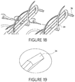
- FIG. 18 is a perspective view of a bushing for a scraper blade of the food processor.
- FIG. 19 is a perspective view of a modified scraper blade for the food processor.
- FIG. 20A A first portion of a representative flow chart is shown as FIG. 20A .
- FIG. 20B A second portion of a representative flow chart is shown as FIG. 20B .
- FIG. 20C A third portion of a representative flow chart is shown as FIG. 20C .
- FIG. 21 is a perspective view of a first configuration of a wand assembly.
- FIG. 22 is an exploded perspective view of a second configuration of a wand assembly.
- FIG. 23 is a perspective view of the wand assembly of FIG. 22 .
- FIG. 24 is an exploded perspective view of a portion of the wand assembly of FIG. 23 .
- the food processor 10 can be any of a variety of configurations including, but not limited to, frozen or chilled food product including but not limited to, beverages such as sodas, beer or wine.
- the food processor 10 includes a food flow path 20 extending from an input or upstream end 22 , such as a reservoir, feed tube or line inlets or hopper 32 to an output or downstream end 24 , such as a dispensing interface 26 from which the food product exits the food processor.
- the food product passes, in a normal or forward direction along the food flow path 20 , from the input end 22 to the output end 24 .
- the dispensing interface 26 includes at least one dispensing valve 28 for selectively passing or allowing passage of the processed food product from the food processor 10 .
- the dispensing interface 26 includes a plurality of dispensing valves 28 , such as but not limited to one, two, three or more.
- the food processor 10 can include any variety of devices, including but not limited to soft serve machines, batch freezers, slush freezers, shake freezers, blended ice machines or food processors for extruding food products which include flows, grains or meats as well as liquid dispensers for beverages including soft drinks, diary drinks or alcoholic beverages such as fermented or distilled spirits.
- the food product can be any corresponding product that may be temperature controlled, mixed, blended, altered, processed or extruded.
- the food flow path 20 incorporates a number of processing stations 30 intermediate the upstream end 22 (such as the hopper) and the downstream end 24 , (such as the dispensing valve 28 ).
- the processing stations 30 can include mixing chambers and temperature control chambers along the food flow path 20 .
- the mixing chambers include chambers for mixing ingredients provided in a stream as well as ingredients from different inputs such that the mixing chamber is the volume of initial combination of different ingredients.
- processing chambers 30 such as the mixing chamber and/or temperature control chamber of FIG. 2 can include a blade or beater assembly 36 for agitation of the food product within the chamber, such as by rotation within the chamber.
- the food flow path 20 can function primarily as a conduit from the input end 22 to the dispensing interface 26 .
- the food processor 10 can function merely to selectively dispense the food product or can provide an alteration or conditioning of the food product such as temperature change, carbonation as well as mixing (compounding).
- Examples of the food processor 10 having these food flow paths 20 include dispensing devices such as automated soda dispensers, beer and wine dispensers.
- the food flow path 20 can include a plurality of inputs 22 with a corresponding smaller or a greater number of outputs 24 depending on the intending operating function of the food processor 10 .
- FIG. 2 A representative food flow path 20 through the food processor, with the reverse direction indicated by arrows, is shown in FIG. 2 .
- the input or upstream end 22 of the food flow path 20 is shown in FIG. 2 , above the output or downstream end, it is understood the input can be located below the output, wherein the food product is pumped up from a supply, hopper or reservoir and along the food flow path to exit at the dispensing interface 26 .
- the present clean in place (CIP) system 40 cooperates with the food processor 10 to selectively pass a solution or a rinse through at least a portion of the food flow path 20 intermediate the downstream end 24 and the upstream end 22 , wherein the introduced solution or rinse travels counter current or reverse to the forward, or normal, direction through the food flow path.
- CIP clean in place
- solution is intended to encompass a cleaning, rinsing, disinfecting or sterilizing solution, as well as combinations or mixtures.
- the present system is set forth in terms of using the solution, however it is understood the term solution encompasses water (or other liquid) such as a rinse that may be employed.
- the term solution also includes a gas or vapor such as steam as well as other disinfecting gas.
- the present system 40 can employ any of a variety of cleaning (and/or disinfecting) materials including liquids, gases and combinations thereof.
- the solution can be at least partly formed by an addition of an acidic or basic wash concentrate to public utility water.
- Exemplary acidic washes for the solution include citric, lactic, malic, acetic, adipic, fumaric, glutaric, tartaric, fumaric, succinic, propionic, aconitic, sorbic, gluconic, ascorbic, and/or humic acids and at least one of sodium dodecyl sulfate and sodium lauryl sulfate.
- the solution is presented to the system 40 at or within a given pressure range.
- the solution can be drawn from a reservoir or supply, wherein a pump (not shown) can be used to pressurize the solution for presentation to the system 40 .
- the solution, or select constituents of the solution are a motive fluid for use in the system.
- the CIP system 40 includes a controller assembly 50 and a manifold assembly 100 , wherein the manifold assembly includes an intake manifold 110 and a distribution manifold 150 ( FIG. 7 ).
- the manifold assembly 100 can further include mounting hardware, such as arms 180 .
- the CIP system 40 can assume a variety of configurations.
- the CIP system is (i) referring to FIG. 3 , a standalone system wherein the controller assembly 50 and the manifold assembly 100 are a single unit that is a separate construction from the food processor 10 and releasably engages the food processor, (ii) referring to FIG. 4 , an integral system, wherein the controller assembly and the manifold assembly are substantially incorporated within or integral with the food processor (either as an after-market or original equipment manufacturer) or (iii) referring to FIG.
- the system 40 is effectively an internal mechanism to the food processor 10 .
- the system becomes a component of the food processor.
- the integral configuration eliminates the need of an operator to engage the system 40 with the food processor 10 every time cleaning is to be performed.
- the integral configuration also simplifies the interface of the manifold assembly 100 and the food processor 10 .
- a door assembly 12 of the food processor can incorporate the manifold assembly to the food processor itself, only requiring an external, or internal liquid and/or gas supply to perform the desired cleaning process.
- the intake manifold 110 and the controller assembly 50 are separated from the distribution manifold 150 , yet operably connected by tubing or piping (umbilical) allowing for functionality as set forth below.
- the hybrid configuration allows for quick change out of the distribution manifold 150 , while retaining standard controller assembly 50 (and intake manifold 110 ) configurations across multiple platforms.
- the controller assembly 50 can be mounted separately from the food processor 10 to provide even greater design flexibility, and reduction of overall weight of the combined system.
- the controller assembly 50 includes control circuitry 60 , a user interface and a control valve 90 ( FIG. 7 ), wherein at least some of the components are retained in a housing 52 and the control valve operates in the intake manifold 110 .
- the housing 52 is water or splash resistant and in certain configurations water or splash proof (for intended operating parameters).
- the controller assembly 50 also includes a power supply 54 and a communications module 70 , as seen in FIG. 6 .
- the intake manifold 110 includes an inlet port 112 for receiving a pressurized source of solution, such as publically available water, into the system 40 and a plurality of outlet ports 114 , wherein the outlet ports are fluidly connected to the distribution manifold 150 .
- the intake manifold 110 includes a single inlet port 112 and two outlet ports 114 .
- the intake manifold 110 can include a plurality of inlet ports 112 and a plurality of outlet ports 114 or a plurality of inlet ports and a single outlet port.
- At least one control valve 90 is located fluidly intermediate the inlet port 112 and the outlet ports 114 .
- the intake manifold 110 includes a single inlet port 112 and two outlet ports 114 , wherein the control valve 90 regulates which outlet port is fluidly connected to the inlet port.
- the controller assembly 50 includes a first 90 a and a second control valve 90 b , wherein flow to each outlet port 114 is regulated by a corresponding control valve.
- the control valves 90 are configured to selectively pass water (solution) from the inlet port 112 through one or a plurality of the outlet ports 114 . That is, the control valves 90 are moveable to provide a flow (including partial or full flow) and no-flow status.
- the control circuitry 60 of the controller assembly 50 is operably connected to the control valves 90 , the user interface 80 and the power supply 54 to provide for control of the passage of the pressurized water from a given inlet port 112 to a given outlet port or ports 114 of the intake manifold 110 .
- control circuitry 60 can include timing circuits 62 as well as counter circuits 64 for controlling the passage of material from the controller assembly 50 , and hence the CIP system 40 . It is understood the control circuitry 60 can incorporate the functionality of commercially available sprinkler systems.
- the control circuitry 60 can be provided in a dedicated processor or programmed into a processor 66 , such as a PCB microprocessor or controller.
- control circuitry 60 can also include a communication module 70 which can include readers 72 such as contact or contactless readers for communicating with RFID or RFID type tags for data storage/identification/controller manipulation. It is also contemplated the control circuitry 60 can include memory 74 , such as but not limited to nonvolatile memory (NVM), wherein the readers allow for receiving internal software NVM/firmware updates.
- a communication module 70 which can include readers 72 such as contact or contactless readers for communicating with RFID or RFID type tags for data storage/identification/controller manipulation.
- memory 74 such as but not limited to nonvolatile memory (NVM), wherein the readers allow for receiving internal software NVM/firmware updates.
- NVM nonvolatile memory
- the communication module 70 and/or control circuitry 60 can include, but is not limited to, capability of bluetooth or Wi-Fi type communication protocol.
- the communication module 70 is capable of sending and receiving data for control specific functions pertaining to the performance of the system 40 and/or data transfer to an external device capable of receiving and storing information externally for later manipulation.
- the communication module 70 can also be configured to communicate/control extensions of the system 40 that are not physically attached to the housing 52 , such as controlling an external valve(s) that also redirects liquid and/or gas based agents such as for introduction through the manifold assembly 100 .
- the communication module 70 can include the reader 72 , such as a wireless, RFID or contactless reader.
- the agents introduced into the system 40 or employed by the system can be accompanied by a tag or card, such as an RFID tag that can be read by the communication module 70 .
- the control circuitry 60 can then identify and verify the additive to ensure compliance with cleaning procedures.
- the system 40 can be programmed to operate only with material from an original equipment manufacturer.
- the communication module 70 can be incorporated into the control circuitry 60 or can be a separate module.
- the communication module 70 provides for communication with an operator to and from the control circuitry 60 through any available channel including, but not limited to wireless and wireless networks such as blue tooth, Wi-Fi, cellular, satellite as well as local WI-FI.
- the communication module 70 can also be configured to communicate directly with the food processor 10 . It is known that certain food processors 10 include a control system for monitoring and reporting, both for diagnostics and processing.
- the communication module 70 of the CIP system 40 can be selected to communicate directly with the food processor 10 and thus respond to use cycles and operation parameters of the food processor to provide efficient and timely cleaning of the food processor under an automated cycle without requiring operator intervention.
- the controller assembly 50 can record operations and thereby provide a record of food processor cleaning.
- the wireless communication via the communication module 70 and associated apps of the user interface provide an external control of the system 40 .
- an operator can remotely control the cleaning process.
- the user interface 80 is sufficiently water resistant to preclude the introduction of liquid into the system 40 through the user interface.
- an operator can program or use the system 40 with damp or wet hands without precluding the intended operation of the system.
- the user interface 80 can be any of a variety of configurations, including touch screen, button or switch operated or application driven, wherein the application is remotely accessed by an operator.
- the user interface 80 can include smart phones, tablets and other portable wirelessly communicating devices and associated apps.
- the user interface 80 encompasses an interface capable of receiving physical user inputs such as a TUI (tactile user interface), shown in FIG. 6 .
- the power supply 54 can be any of a variety of constructions.
- the power supply 54 is a battery, which can be either disposable or rechargeable (such as by a power docking station), depending on the intended operating environment of the system.
- the power supply 54 can be drawn from available electrical supply, wherein commercially available converters or transformers are intermediate the available power supply and the control circuitry 60 .
- the power supply 54 can be provided by a wireless interaction such as inductive power transfer, either to directly power or to charge a battery that then powers the system.
- the power supply 54 can be provided by solar energy, hydrogen conversion or scrubbing of available waste energy.
- the power supply 54 can be dry cell batteries, AC/DC inlet from wall outlet, rechargeable power supplies, either removable or embedded in the housing as well as rechargeable by a cable or wireless charging technology.
- the manifold assembly 100 includes the intake manifold 110 and the distribution manifold 150 .
- the distribution manifold 150 is shown having a number of inputs 154 corresponding to the number of outlets 114 of the intake manifold 110 .
- the distribution manifold 150 includes a first and a second input 154 a , 154 b and a plurality of output openings 156 .
- the specific number of inputs 154 and outputs 156 is dictated by the intended operating environment of the system 40 , and is not limited to the illustrated configuration.
- the first and second inputs 154 a , 154 b correspond to and operably align with the outlet ports 114 a , 114 b of the intake manifold 110 for receiving flow from the corresponding first and second outlet ports of the intake manifold.
- the output openings 156 are in fluid communication with the first and the second inputs 154 a , 154 b .
- the number of output openings 156 corresponds to the number of dispensing interfaces 26 , dispensing valves or processing paths of the food processor 10 .
- the manifold assembly 100 and specifically the distribution manifold 150 also includes an induction port 170 for introducing an agent into the solution.
- the induction port 170 is fluidly intermediate the input 112 and the output 156 of the manifold assembly 100 and particularly the input 154 and output 156 of the distribution manifold 150 .
- pressurized water is the motive fluid and the induction port 170 introduces an additional component or agent to the solution.
- the agent is passed through the induction port 170 by any of a variety of mechanisms, such as pumping, metering or venturi.
- the manifold assembly 100 such as the distribution manifold 150 , includes a venturi (not shown), wherein the solution or motive fluid passes through the venturi to create a reduced pressure, wherein the reduced pressure is used to introduce the agent through the induction port 170 .
- a pump or metering device can be used independently or in conjunction with the venturi of the manifold assembly 100 to introduce the agent into the solution.
- each input 154 is fluidly connected to each output 156 of the distribution manifold 150 (and hence manifold assembly 100 ) and one induction port 170 , such as the venturi, is fluidly intermediate each input and output.
- each flow path between the input 154 and the downstream output 156 in the distribution manifold 150 can include one venturi (not limited to one), material or a gas may be drawn into the passing flow.
- a plurality of induction ports 170 (such as a venturi) can be located along the flow path in the manifold assembly 100 between a given input and output.
- the plurality of induction ports 170 provides for the introduction of a plurality of agents to the motive fluid.
- a low pressure port of the venturi is fluidly connected to a supply or source of an agent, wherein the agent can be liquid, solid or gas, such as ambient pressure air. As ambient air is drawn into the venturi and the flow, bubble agitation is formed.
- the downstream induction port 170 (such as the low pressure port of the second venturi between the input and the output) is fluidly connected to a supply or source of the agents, such as cleaning, disinfecting or sterilizing agents, so that the introduced agent is mixed into the aerated flow.
- agents such as cleaning, disinfecting or sterilizing agents
- the distribution manifold 150 (or manifold assembly 100 ) can include a single induction port 170 fluidly intermediate the input and the output.
- each flow path in the distribution manifold 150 (or manifold assembly 100 ) between the input and the output can include a corresponding induction port.
- the distribution manifold 150 can include a variety of configurations of input(s) 154 , induction port(s) 170 , outputs 156 and interconnecting flow paths. These configurations can be selected to provide predetermined flows from each of the outputs 156 under anticipated operating conditions. Thus, depending on the desired performance, each output 156 can provide the same flow rate. That is, the construction of the distribution manifold 150 can be tuned to provide the desired flows from the outputs 156 .
- the distribution manifold 150 includes at least one but may have a plurality of inputs 154 .
- One or more of the inputs 154 can include at least one induction port 170 to allow the addition of other gas or liquids to the solution.
- the induction port 170 can cooperate with a venturi or an active mechanism such as a pump or meter.
- agents gas or liquid
- the flow path in the distribution manifold 150 can include a return portion 158 after (downstream of) the most downstream output 156 , wherein the return portion is fluidly connected to the input 154 upstream of the most upstream output.
- the incorporation of the return portion 158 as seen in FIG. 9 allows each of the outputs 156 to have an equal cross sectional area, or diameter for circular outputs, wherein the flow from each output is equal. This eliminates the need to tune the outlet ports 156 with different diameters, which would otherwise be required in order to get the same amount of flow from each output.
- the flow path in the distribution manifold 150 does not include the return portion 158 .
- the cross sectional area of each output is formed to accommodate the associated pressure at the particular location in the flow path.
- the outputs 156 exposed to higher flow pressures in the distribution manifold 150 have a smaller cross sectional area than outputs exposed to lower pressures.
- the distribution manifold 150 can include one or a plurality of inputs 154 .
- One or several inputs 154 can include at least one induction port to allow the addition of other liquids and/or gas.
- the cross sectional areas of the outputs 156 is specifically tuned per application in order to make the flow equal between outputs.
- the distribution manifold 150 again includes at least one, but may have several inputs 154 , wherein at least one of the inputs includes an induction port 170 to allow the addition of other liquids and/or gas.
- the cross sectional area of the outputs is specifically sized, tuned, per application in order to make the liquid flow equal between outlet ports.
- an access port or hatch, detachable or refillable reservoir or dispenser can be provided along with, or in place of the induction port 170 for the operator to introduce agents or additives into the flow path.
- the distribution manifold 150 includes at least one, but may have a plurality of inputs 154 . At least one of the inputs 154 can include the induction port 170 to allow the addition of other liquids and/or gas to the solution. In this configuration with input symmetrically centered with the output 156 , no tuning of the output is required.
- the distribution manifold 150 includes at least one, but may have several inputs 154 , wherein at least one of the inputs includes an induction port 170 to allow the addition of other liquids and/or gas. In this configuration having only a single output 156 , no tuning of the outlet port is required.
- the tuning of the distribution manifold 150 may not always be required for the system 40 to be operational, and such tuning can be selected to provide enhanced control over the exposure of the food processor 10 to the solution. Particularly, if regulation of the flow from each output 156 is not critical, the tuning of the distribution manifold 150 can be decreased.
- the manifold assembly 100 (including at least one of the intake manifold 110 and the distribution manifold 150 ) or an input 112 to the manifold assembly can include an ultrasonic generator 180 to impart pressure waves in the solution sufficient to create cavitation in the solution.
- the ultrasonic generator 180 can be internal or external to the food processor 10 or the system 40 , thus introducing cavitation in the solution at any location along the food flow path 20 .
- the ultrasonic generator 180 can be piezoelectric or magnetostrictive transducers as well as sonifier or sonicators, wherein the sonication can be direct or indirect.
- the solution can be in contact with a probe or can be isolated or separated from the probe. Commercially available sonifier or sonicators can be employed in the system.
- each output of the distribution manifold 150 includes a wash barrel 160 , as shown in FIG. 7 , sized to be at least partially received within the dispensing interface 26 of the food processor 10 .
- the wash barrel 160 is configured to physically contact a corresponding dispensing valve 28 of the food processor 10 , such that upon operable engagement of the manifold assembly 100 with the food processor, each wash barrel contacts a corresponding dispensing valve of the food processor and disposes the corresponding dispensing valve in an open (or flow passing) position.
- the wash barrel 160 includes or defines a flow path extending along a longitudinal dimension of the wash barrel. Depending upon the specific design of the dispensing valve 28 in the food processor 10 , the wash barrel 160 includes a transverse exit port 161 for passing liquid from the flow path. The wash barrel 160 also includes an engaging surface 162 for engaging the dispensing valve 28 and moving the dispensing valve to the open position in response to operable engagement of the wash barrel and the dispensing interface 26 of the food processor 10 . The wash barrel 160 also forms a sealed connection with the dispensing interface 26 to provide for fluid transfer to the food flow path 20 .
- dispensing pistons which reside within the dispensing interface 26 can be first removed before installing the manifold assembly 100 (and the wash barrel(s) 160 ).
- the wash barrel(s) include a sealing surface 164 for contacting the food processor 10 to create a seal for ensuring passage of the solution into the food flow path 20 .
- the manifold assembly 100 includes an interconnect mechanism 120 for operably engaging and retaining the manifold assembly, and any affixed components relative to the food processor 10 , and specifically the dispensing interface 26 .
- a pair of mounting arms 122 are rotatably mounted to the manifold assembly 100 , wherein the mounting arms can be moved between a release position and an engaged position. In the engaged position, the mounting arms 122 operably retain the manifold assembly 100 and the attached controller assembly 50 relative to the food processor 10 .
- the system 40 could rotate or snap into operable engagement with the food processor 10 without requiring independent mounting arms 122 or movement of such mounting arms.
- control assembly 50 and manifold assembly 100 are configured to provide sufficient pressurization of the food flow path 20 .
- the system 40 includes a pressure cover 42 for substantially sealing the upstream end of hopper-by-pass tube(s) 44 and tubing, which extend from the hopper(s) product inlet orifice(s).
- the pressure cover 42 includes a lid 43 and seated seal 45 for engaging a corresponding surface adjacent a periphery of the hopper 32 or engaging the periphery of the hopper.
- the pressure cover 42 also includes a drain port for passing solution that has flowed counter current through the food flow path 20 .
- a drain line(s) is connected to the drain port to direct the passed solution to a catch basin or disposal.
- the pressure cover 42 and the by-pass tube(s) 44 sufficiently seal the hopper(s) and inlet orifice(s) so that pressure of the cleaning solution entering the hopper by-pass-tube(s) 44 is sufficient to force material into and through the drain port.
- an insert hopper, with associated drain line can be temporarily located within the system hopper.
- the insert hopper/or hopper sealed cover 42 can be located within/or top mounted to the food processor hopper, wherein the insert/or cover hopper is sized to be spaced/or seal fitted from the food processor hopper so that solution can pass between/or within the hopper(s) and into the insert/or within the hopper itself.
- the by-pass tube(s) 44 sufficiently seal hopper(s) outlet orifice(s) 34 so that pressure of the cleaning solution entering the hopper by-pass-tube(s) is sufficient to force material into and through the drain port.
- the bypass tube 44 connects to the food processor 10 by inserting into the product mix ports 34 in the bottom of the hopper 32 .
- the bypass tubes 44 can be held in place by either active (mechanical) or non-active (interference fit) engagement.
- the connected bypass tubing 44 dispenses the machine waste into a catch basin or floor drain.
- an insert hopper/or hopper sealed cover 42 can be located within/or top mounted to the food processor hopper, wherein the insert/or cover hopper is sized to be spaced/or seal fitted from the food processor hopper so that solution can pass between/or within the hopper(s) and into the insert/or within the hopper itself.
- the bypass assembly of the present system fluidly connects to the food flow path 20 in the food processor 10 intermediate the upstream end 22 and the downstream end 24 of the food flow path.
- the bypass assembly includes the bypass line 44 fluidly connected to the food flow path 20 intermediate the upstream end 22 and the downstream end 24 of the flow path. That is, as seen in FIG. 15 , the bypass line 44 connects to the food flow path 20 at a location downstream (in the normal or forward direction of product along food flow path in the food processor) and terminates at a point outside of the food flow path. Referring to FIG. 15 , in one configuration, the bypass line 44 fluidly connects to the food flow path 20 at the exit of the hopper 32 and terminates in a drain or catch basin.
- solution introduced into the food flow path 20 at the dispensing interface 26 and flowing in the reverse direction along the food flow path passes into the bypass line 44 without contacting the material in the hopper 32 and the solution is guided from the food processor 10 through the bypass line without contacting any material in the hopper.
- the food processor 10 includes a bushing or bearing 14 for retaining or locating a beater assembly 36 as seen in FIG. 1 .
- the bushing 14 provides a wearable interface between a rotatable beater bar 38 and the mandrel or chiller tubes.
- the present system employs a modified bushing 14 having a flow port 15 allowing water or solution to flow to both sides (upstream and downstream side) of the bushing.
- solution from the manifold assembly 100 can migrate between the bushing 14 and the surrounding portion of the food processor 10 thereby allowing more complete exposure of the food path to the introduced solution. That is, the bushing 14 has an internal surface and an external surface, wherein the flow port 15 connects the internal surface to the external surface.
- the present system modifies the beater blade 38 of the food processor 10 .
- the present beater blade 38 includes a plurality of flow holes 39 through the beater blade, wherein the flow holes permit the introduced solution, flowing in the reverse direction along the food flow path 20 , to migrate between the beater bar in the beater blade, thereby providing further cleaning. It has been found advantageous to employ the apertures 39 in the beater blade 38 for food product having a relatively high fat content, such at least 8% as well as 10 to 12% or more fat content. For food product having particulate matter, such as seeds or solid food particles (cookies in dairy dessert), the beater blade 38 is employed without flow holes.
- the beater blade 38 is modified to include only one surface contacting member to a beater barrel of the food processor 10 . That is, only a single beater blade edge contacts the beater barrel. As seen in the FIG. 18 , the beater bar supports two beater blades 38 , however the modification removes one of the blades so only one edge of one beater blade contacts the barrel.
- a sealant is located between the beater bar and the beater blade 38 to form a self-conforming configuration of the beater blade and forms a one-to-one seal between the beater bar and the beater blade, thereby reducing migration of product between the beater bar and the beater blade.
- a commercially available food grade sealant can be used between the beater blade 38 and the beater bar. This reduces the amount of fluid used to clean the machine and reduces the cycle time of the system 40 . It is understood any combination of these beater blade, beater bar configurations can be employed.
- the present system also optionally self-lubricating O-rings and seals 16 in place of traditional food grade grease for sealing.
- the use of self-lubricating O-rings and seals 16 allows for the elimination of a food safe lubrication to place the food processor in an operable status. As the reintroduction of the food grade lubricant is not necessary after cleaning, the present system 40 provides for reduced maintenance time.
- Satisfactory self-lubricating O-rings and seals 16 include commercially available plastic or elastomer O-rings and seals impregnated with approximately 3%-5% polytetrafluoroethylene (PTFE) or bearing, but not limited to a PTFE coating as commercially available.
- PTFE polytetrafluoroethylene
- the present O-rings and food contacting sealing surfaces 16 include a PTFE (Teflon® coating a registered mark of E. I. Du Pont De Nemours and Company Corporation) coating or impregnation, thereby removing the need for removal and reapplication of food grade grease.
- PTFE Teflon® coating a registered mark of E. I. Du Pont De Nemours and Company Corporation
- the operator mechanically connects the manifold assembly 100 to the dispensing interface 26 of the food processor 10 by engaging the mounting arms 122 with the food processor, as shown in FIG. 14 .
- the wash barrels 160 contact the corresponding dispensing valves 28 of the food processor 10 and upon operable engagement of the manifold assembly 100 to the food processor 10 , the wash barrels dispose the dispensing valves to the open position.
- One induction port 170 of the manifold assembly 100 is connected to a supply of cleaning, disinfecting or sterilizing solution as depending upon the intended cleaning process, and the remaining induction port may be allowed to aspirate ambient air.
- the inlet port 112 of the intake manifold 110 is connected to the public utility water supply or a portable pressurized water supply and thus a positive pressure is placed upon the control valves 90 .
- the operator then programs the controller assembly 50 via the available user interface 80 for the desired cleaning (wash)—rinse cycles. For example, the operator can select from one of three options: (i) Rinse only; (ii) Wash only and (iii) Rinse-Wash cycle. Alternatively a second and final rinse cycle can be performed if the operator desires to rinse out the wash solution residual prior to reintroducing the food product mix back into the machine. That is, the controller assembly 50 can include a number of predetermined rinse, wash or combination cycles along with preset soak times.
- bypass lines 44 may be fluidly connected to the ports 34 of the hoppers such that introduced solution passes through the bypass tubes 44 rather than contacting the hopper and thus does not contact any material within the hoppers, thereby permitting the operator to minimize the waste of food product, while reducing entire cleaning cycle time.
- the bypass lines 44 are placed in the hoppers after the operator cleans the hopper using the wand assembly and/or sanitation wipes.
- the drain line(s) are connected to the drain port(s).
- the controller assembly 50 selectively controls the control valves 90 corresponding to the input program to pass water or solution through the wash barrel(s) 160 and into the open dispensing valve(s) 28 of the food processor 10 .
- the introduced water/solution passes countercurrent through the food flow path 20 in the food processor 10 and the apertures in the bushings 14 and beater blades 38 (if employed).
- the controller assembly 50 is also operatively connected to the ultrasonic generator 180 for selectively operating the generator to introduce corresponding cavitation in the solution.
- the controller assembly 50 can control the optional aspiration of air into the flow via the induction port 170 including a first venturi.
- the controller assembly 50 provides for the selective introduction of bubbles into the counter current flow, wherein the bubbles enhance the cleaning action of the rinse. It is believed the bubbles increase turbulence and kinetic energy in the passing flow, thereby enhancing the cleaning action.
- the cleaning solution ultimately passes into the bypass tubes 44 and may be captured or disposed of down the available drain. Alternatively, if the bypass lines 44 are not employed, the solution passes from the drain port 47 in the pressure cover 42 for disposal.
- the present system 40 Upon completing the programmed cycles, the present system 40 automatically terminates the flow of solutions—rinses through the food processor.
- the present system 40 can be then disconnected from the dispensing interface 26 of the food processor 10 and the bypass tubes 44 removed from the hopper(s) 32 (or the pressure cover 42 removed) thereby allowing for normal operation of the food processor, subsequent to the present clean in place.
- valves interconnecting the manifold assembly and the food flow path are closed, thereby isolating the system from the food flow path.
- FIGS. 20A, 20B, and 20C A representative flow chart is shown through combinations of FIGS. 20A, 20B, and 20C .
- the present system can further include a wand assembly 200 comprising a wand manifold 220 and a wand 260 , wherein the wand can be connected to the wand manifold by an interconnecting hose(s) 250 .
- the wand manifold 220 includes a separate water inlet port 222 such as for receiving water from the public utility supply or other pressurized sources.
- the wand manifold 220 includes an induction port 230 such as a venturi 232 for aspirating or drawing in a cleaning, disinfecting or sterilizing solution, wherein the solution is passed for selective dispensing by the wand 260 .
- an induction port 230 such as a venturi 232 for aspirating or drawing in a cleaning, disinfecting or sterilizing solution, wherein the solution is passed for selective dispensing by the wand 260 .
- the wand manifold 220 can allow for an optional supply of fresh water supply.
- the ability to select substitute cleaners is set by the configuration of the wand 260 or wand manifold 220 itself by the operator.
- a plurality of venturi and/or metering pumps can be connected to the wand manifold 220 .
- a flow meter(s) can be used in conjunction with an onboard micro-processor, which could be powered in many different ways i.e. replaceable batteries, re-chargeable batteries, directly connected to a continuous power supply.
- the wand assembly 200 can also contain a communication module 270 as set forth above, and thus have for example RFID technology that records and confirms OEM solutions are being used to keep the integrity of the system as intended.
- the wand manifold 220 can be as simple as a clear tube, such as a clear tube, for the purpose of housing at least one inlet induction port into the directed flow path.
- the wand manifold 220 can be intelligent with flow sensor(s), temperature sensor(s), chemical sensor(s), valve(s), microprocessor(s) capable of controlling and sensing flow through the wand manifold and reporting information in real time and post processing by means of the communication module as set forth above, such as RFID, Bluetooth, Wi-Fi.
- the wand assembly 200 can be integrated into the CIP system 40 , so that the controller assembly 50 can operate both the manifold assembly 100 and the wand assembly 200 . Further, the manifold assembly 100 can be fluidly connected to the wand assembly 200 so that the composition of solution flow through the wand assembly is controlled by the control circuitry 60 of the controller assembly 50 .
- actuation of the wand permits flow through the induction port 170 or venturi 172 .
- the wand assembly 200 can be selected to accommodate two different and selectable flow rates.
- the wand 260 and venturi 172 are selected such that (i) a first flow rate which does not draw in the additive (agent)—thereby providing an additive free rinse and (ii) a second flow rate which draws the solution into the passing flow.
- the flow rates can be provided by operating positions of the wand 260 , such as a position of the tip or an orientation of the tip or mechanical flow control such as valving or selective flow obstruction.
- the present system may be stored on a rack 280 for retaining the controller assembly 50 , the wand manifold 220 as well as supplies of cleaning solution and the wand assembly.
- the present system 40 has been set forth as providing for passage of the solution counter current (or reverse) of the forward flow through the food flow path 20 in the food processor 10 , it is understood the system can be operably located at an upstream position or upstream end of the food flow path to pass the solution in a forward direction along the food flow path.
- agents or additives can be introduced by the operator introducing such agents or additives through an access door or port during a flow or no-flow status of the system 40 .
Landscapes
- Engineering & Computer Science (AREA)
- Mechanical Engineering (AREA)
- Food Science & Technology (AREA)
- Chemical & Material Sciences (AREA)
- Polymers & Plastics (AREA)
- Life Sciences & Earth Sciences (AREA)
- Chemical Kinetics & Catalysis (AREA)
- General Chemical & Material Sciences (AREA)
- Food-Manufacturing Devices (AREA)
- Cleaning By Liquid Or Steam (AREA)
- Devices For Dispensing Beverages (AREA)
- General Preparation And Processing Of Foods (AREA)
- Apparatuses For Bulk Treatment Of Fruits And Vegetables And Apparatuses For Preparing Feeds (AREA)
Abstract
Description
Claims (20)
Priority Applications (1)
| Application Number | Priority Date | Filing Date | Title |
|---|---|---|---|
| US15/813,954 US10595676B2 (en) | 2013-09-16 | 2017-11-15 | Manifold assembly and wash barrel for soft serve machine |
Applications Claiming Priority (5)
| Application Number | Priority Date | Filing Date | Title |
|---|---|---|---|
| US201361878472P | 2013-09-16 | 2013-09-16 | |
| PCT/US2014/053495 WO2015038360A1 (en) | 2013-09-16 | 2014-08-29 | Automated cleaning system for food processor and method |
| US201514758112A | 2015-06-26 | 2015-06-26 | |
| US15/340,629 US9962035B2 (en) | 2013-09-16 | 2016-11-01 | Automated cleaning system for food processor and method |
| US15/813,954 US10595676B2 (en) | 2013-09-16 | 2017-11-15 | Manifold assembly and wash barrel for soft serve machine |
Related Parent Applications (1)
| Application Number | Title | Priority Date | Filing Date |
|---|---|---|---|
| US15/340,629 Continuation US9962035B2 (en) | 2013-09-16 | 2016-11-01 | Automated cleaning system for food processor and method |
Publications (2)
| Publication Number | Publication Date |
|---|---|
| US20180070767A1 US20180070767A1 (en) | 2018-03-15 |
| US10595676B2 true US10595676B2 (en) | 2020-03-24 |
Family
ID=52666164
Family Applications (12)
| Application Number | Title | Priority Date | Filing Date |
|---|---|---|---|
| US14/758,112 Active US9516889B2 (en) | 2013-09-16 | 2014-08-29 | Automated cleaning system for food processor and method |
| US14/886,672 Active 2036-09-19 US10398256B2 (en) | 2013-09-16 | 2015-10-19 | Automated cleaning system for food processor and method |
| US15/238,334 Active US9730550B2 (en) | 2013-09-16 | 2016-08-16 | Automated cleaning system for food processor and method |
| US15/340,629 Active US9962035B2 (en) | 2013-09-16 | 2016-11-01 | Automated cleaning system for food processor and method |
| US15/813,931 Active US10595675B2 (en) | 2013-09-16 | 2017-11-15 | Manifold assembly with wash barrel for soft serve machine |
| US15/813,891 Active US10595674B2 (en) | 2013-09-16 | 2017-11-15 | Automated cleaning system for food processor and method |
| US15/813,804 Active US10595673B2 (en) | 2013-09-16 | 2017-11-15 | Automated cleaning system for food processor and method |
| US15/813,756 Active US10595672B2 (en) | 2013-09-16 | 2017-11-15 | Automated cleaning system for food processor and method |
| US15/813,854 Active US10602877B2 (en) | 2013-09-16 | 2017-11-15 | Manifold assembly for soft serve machine |
| US15/813,954 Active US10595676B2 (en) | 2013-09-16 | 2017-11-15 | Manifold assembly and wash barrel for soft serve machine |
| US16/826,841 Active US11337549B2 (en) | 2013-09-16 | 2020-03-23 | Automated cleaning system for food processor and method |
| US17/735,552 Active 2035-02-13 US12053118B2 (en) | 2013-09-16 | 2022-05-03 | Automated cleaning system for food processor and method |
Family Applications Before (9)
| Application Number | Title | Priority Date | Filing Date |
|---|---|---|---|
| US14/758,112 Active US9516889B2 (en) | 2013-09-16 | 2014-08-29 | Automated cleaning system for food processor and method |
| US14/886,672 Active 2036-09-19 US10398256B2 (en) | 2013-09-16 | 2015-10-19 | Automated cleaning system for food processor and method |
| US15/238,334 Active US9730550B2 (en) | 2013-09-16 | 2016-08-16 | Automated cleaning system for food processor and method |
| US15/340,629 Active US9962035B2 (en) | 2013-09-16 | 2016-11-01 | Automated cleaning system for food processor and method |
| US15/813,931 Active US10595675B2 (en) | 2013-09-16 | 2017-11-15 | Manifold assembly with wash barrel for soft serve machine |
| US15/813,891 Active US10595674B2 (en) | 2013-09-16 | 2017-11-15 | Automated cleaning system for food processor and method |
| US15/813,804 Active US10595673B2 (en) | 2013-09-16 | 2017-11-15 | Automated cleaning system for food processor and method |
| US15/813,756 Active US10595672B2 (en) | 2013-09-16 | 2017-11-15 | Automated cleaning system for food processor and method |
| US15/813,854 Active US10602877B2 (en) | 2013-09-16 | 2017-11-15 | Manifold assembly for soft serve machine |
Family Applications After (2)
| Application Number | Title | Priority Date | Filing Date |
|---|---|---|---|
| US16/826,841 Active US11337549B2 (en) | 2013-09-16 | 2020-03-23 | Automated cleaning system for food processor and method |
| US17/735,552 Active 2035-02-13 US12053118B2 (en) | 2013-09-16 | 2022-05-03 | Automated cleaning system for food processor and method |
Country Status (8)
| Country | Link |
|---|---|
| US (12) | US9516889B2 (en) |
| EP (2) | EP3046867B1 (en) |
| CN (1) | CN106029552B (en) |
| AU (2) | AU2014318188B2 (en) |
| CA (1) | CA2924481C (en) |
| ES (2) | ES2925258T3 (en) |
| MX (1) | MX378656B (en) |
| WO (1) | WO2015038360A1 (en) |
Families Citing this family (43)
| Publication number | Priority date | Publication date | Assignee | Title |
|---|---|---|---|---|
| US10006656B1 (en) * | 2013-05-24 | 2018-06-26 | Steve A. Parks | Dispenser apparatus and method |
| EP3046867B1 (en) | 2013-09-16 | 2022-05-04 | Idea Boxx, LLC | Apparatus and method for cleaning a food processor |
| FR3021715B1 (en) * | 2014-05-28 | 2016-05-20 | Pcm | DISPENSING DEVICE AND ASSEMBLY OF SUCH DELIVERY DEVICES |
| US10285417B2 (en) * | 2015-01-09 | 2019-05-14 | Ali Group S.R.L.—Carpigiani | Machine and method for making two liquid or semi-liquid food products |
| WO2017100681A1 (en) * | 2015-12-11 | 2017-06-15 | Idea Boxx, Llc | Flow balancing in food processor cleaning system |
| US9764880B2 (en) * | 2016-02-05 | 2017-09-19 | The Vollrath Company, L.L.C. | Hopper cover |
| US11198839B2 (en) | 2016-05-18 | 2021-12-14 | Lg Electronics Inc. | Beverage making apparatus |
| CN107400586B (en) | 2016-05-18 | 2021-05-28 | Lg电子株式会社 | Beer brewing device |
| CN107400583B (en) | 2016-05-18 | 2021-07-13 | Lg电子株式会社 | Beer brewing bag and beer brewing device having the same |
| CN107400582B (en) * | 2016-05-18 | 2021-06-29 | Lg电子株式会社 | Beer brewing device |
| CN107400585B (en) * | 2016-05-18 | 2021-07-30 | Lg电子株式会社 | Beer brewing device |
| CN107400588B (en) | 2016-05-18 | 2021-08-03 | Lg电子株式会社 | Beer brewing device |
| CN107418805B (en) * | 2016-05-18 | 2021-08-03 | Lg电子株式会社 | Beer brewing device |
| US11208621B2 (en) * | 2016-05-18 | 2021-12-28 | Lg Electronics Inc. | Beverage-making apparatus |
| US11224306B2 (en) * | 2016-05-18 | 2022-01-18 | Lg Electronics Inc. | Beverage-making apparatus |
| US10503177B2 (en) * | 2016-08-03 | 2019-12-10 | Safe Harbor Associates LLC | Additive delivery system with sensors |
| CN106264148B (en) * | 2016-11-04 | 2022-07-15 | 牛村科技(深圳)有限公司 | Stirring linkage assembly and milk preparing machine |
| US10898031B2 (en) | 2016-11-16 | 2021-01-26 | F'real Foods Llc | Modular blender with improved water heating and light beam detection |
| CN106583378B (en) * | 2016-11-25 | 2020-08-14 | 杭州易杯食品科技有限公司 | Cleaning method of capsule beverage machine |
| EP3566012A1 (en) * | 2017-02-09 | 2019-11-13 | RTA Associates, LLC | Food processor with integrated agitation treating |
| US11717005B2 (en) * | 2017-06-26 | 2023-08-08 | Taylor Commercial Foodservice, Llc | Method and apparatus for reducing required frequency for manual cleaning of at least portions of a food flow path in a food processor |
| CN109549494B (en) * | 2017-09-25 | 2021-10-26 | 佛山市顺德区美的电热电器制造有限公司 | Cooking appliance and method for energizing the same |
| CN110236406B (en) * | 2018-03-09 | 2022-04-19 | (株)酷晨 | Food heating kettle |
| NL2021604B1 (en) * | 2018-09-11 | 2020-06-26 | Vitens N V | Use of a fulvic acid-containing starting material. |
| CN113195397A (en) * | 2018-12-21 | 2021-07-30 | 三得利控股株式会社 | Cleaning device of beverage machine |
| US12029224B2 (en) * | 2019-10-11 | 2024-07-09 | H.C. Duke & Son, Llc | Automated clean in place system for soft serve machine |
| EP3847898B1 (en) * | 2020-01-10 | 2022-12-21 | Frigomat S.r.l. | Machine for the production of liquid, semi-liquid or pasty solid food products equipped with automatic washing system and method for cleaning such a machine |
| CN113522900B (en) * | 2020-04-14 | 2022-10-04 | 九阳股份有限公司 | Cleaning and maintaining method of food processor and food processor |
| CN116325082B (en) * | 2020-10-23 | 2025-11-25 | 胜高股份有限公司 | Washing method for piping in a single-wafer washing unit |
| US11524886B2 (en) * | 2021-02-05 | 2022-12-13 | Cana Technology, Inc. | Ingredients cartridge for a beverage mixture dispensing system |
| US12478078B2 (en) | 2022-04-18 | 2025-11-25 | FBS Partnership, LP | Sealed, self-cleaning, food dispensing system |
| US12588684B2 (en) | 2022-04-18 | 2026-03-31 | Fbd Partnership, Lp | Sealed, self-cleaning, food dispensing system with variable overrun control |
| CN115950712B (en) * | 2023-03-08 | 2023-05-09 | 淄博市产品质量检验研究院 | Sampling device for solid food detection |
| CN116584829B (en) * | 2023-06-01 | 2024-07-09 | 杭州九阳小家电有限公司 | Automatic cleaning method for food processing machine |
| US12279629B1 (en) | 2024-01-18 | 2025-04-22 | Sharkninja Operating Llc | Mixing vessel baffles for a drink maker |
| US20250234886A1 (en) | 2024-01-18 | 2025-07-24 | Sharkninja Operating Llc | Removeable collection tray for a drink maker |
| US12593855B2 (en) | 2024-01-18 | 2026-04-07 | Sharkninja Operating Llc | Drink maker with detachably connectable mixing vessel |
| USD1076580S1 (en) | 2024-01-18 | 2025-05-27 | Sharkninja Operating Llc | Drink maker dasher |
| TWI870298B (en) * | 2024-05-07 | 2025-01-11 | 財團法人食品工業發展研究所 | Quick-release connector for raw material end of beverage machine and cleaning method of beverage machine |
| US12520857B1 (en) | 2025-01-09 | 2026-01-13 | Sharkninja Operating Llc | Multi-stage dispenser assembly |
| US12514262B1 (en) | 2025-01-10 | 2026-01-06 | Sharkninja Operating Llc | Feature for preventing material buildup in a mixing vessel of a drink maker |
| US12414578B1 (en) | 2025-03-14 | 2025-09-16 | Sharkninja Operating Llc | Shared output connector assembly for two drink maker dispenser assemblies |
| CN119819662B (en) * | 2025-03-17 | 2025-06-06 | 杭州亿诺机器人有限公司 | Milk tea machine pipeline cleaning device and method |
Citations (67)
| Publication number | Priority date | Publication date | Assignee | Title |
|---|---|---|---|---|
| US2563385A (en) | 1951-08-07 | Apparatus fok cleaning beek | ||
| US3120326A (en) | 1960-08-26 | 1964-02-04 | Robert M Hedeman | Beverage dispenser conduit purging device |
| US3273585A (en) | 1966-09-20 | Flushing apparatus for dispensing freezers | ||
| US3566904A (en) | 1969-04-15 | 1971-03-02 | Atomic Energy Commission | Liquid flow control system |
| US3729177A (en) | 1972-02-18 | 1973-04-24 | Beatrice Foods Co | In-place cleaning system |
| US3898859A (en) | 1974-02-13 | 1975-08-12 | Duke H C & Son Inc | Apparatus and method for the preparation of soft serve products |
| GB1562274A (en) | 1978-03-16 | 1980-03-12 | Schweppes Ltd | Beverage dispensing |
| US4330245A (en) | 1980-05-05 | 1982-05-18 | Fmc Corporation | Apparatus for producing frozen confections |
| US4378034A (en) | 1978-05-22 | 1983-03-29 | Albertson Robert V | Method of cleaning, and filling liquid accommodating apparatus |
| US4404040A (en) | 1981-07-01 | 1983-09-13 | Economics Laboratory, Inc. | Short chain fatty acid sanitizing composition and methods |
| US4417610A (en) | 1981-03-31 | 1983-11-29 | O.G. Hoyer A/S | Dispenser systems |
| US4479423A (en) | 1983-11-21 | 1984-10-30 | Taylor Freezer Company | Continuous-flow type apparatus for pasteurizing batches of product |
| US4703628A (en) | 1984-08-10 | 1987-11-03 | Sanyo Electric Co. | Apparatus for preparing frozen products |
| US4848381A (en) | 1987-02-13 | 1989-07-18 | Diversey Corporation | Clean in place system |
| US4860550A (en) | 1987-08-08 | 1989-08-29 | Sanyo Electric Co., Ltd. | Apparatus for preparing ice creams |
| US4941593A (en) | 1989-01-11 | 1990-07-17 | Hicks Robert C | Cleaning system for beverage delivery conduits |
| US5330769A (en) | 1992-11-09 | 1994-07-19 | West Agro, Inc. | Acid sanitizer |
| WO1995015090A2 (en) | 1993-12-01 | 1995-06-08 | Food Systems Partnership, Ltd. | Soft serve frozen dessert machine |
| US5436008A (en) | 1992-12-11 | 1995-07-25 | Ecolab Inc. | Sanitizing compositions |
| US5463878A (en) | 1992-11-03 | 1995-11-07 | Froezert Usa, Inc. | Chilled product dispensing apparatus |
| US5535923A (en) | 1993-01-25 | 1996-07-16 | Kirin Beer Kabushiki Kaisha | Washing apparatus for beverage pouring apparatus |
| US5615695A (en) | 1995-12-15 | 1997-04-01 | Chambers; Harvey E. | Pulsater fluid system flusher |
| US5700494A (en) | 1992-11-25 | 1997-12-23 | 9000-9226 Quebec Inc. | Device for producing a shaped confection of edible materials combined into co-extensive strips |
| US5738002A (en) | 1996-11-04 | 1998-04-14 | Marano-Ducarne; Anthony | Self-cleaning espresso machine attachment for producing frothed hot milk |
| US5911813A (en) | 1995-07-17 | 1999-06-15 | Gram A/S | Confectionery dispenser with detergent cleaning system |
| US5948439A (en) | 1997-10-31 | 1999-09-07 | Farmo-Nat Ltd. | Effervescent granules |
| US6136362A (en) | 1998-12-10 | 2000-10-24 | Alfa Laval Flow Inc. | High temperature/short time pasteurization system and method of cleaning |
| WO2000070963A1 (en) | 1999-05-20 | 2000-11-30 | Specialty Equipment Companies, Inc. | Valve and door assembly for a semi-frozen food dispensing machine |
| US20010017485A1 (en) | 1999-05-27 | 2001-08-30 | Yoo Wan Sik | Control system and method for switching and intercepting power supplies |
| US20020043071A1 (en) * | 2000-08-18 | 2002-04-18 | Frank Jimmy I. | Frozen beverage machine |
| US6472358B1 (en) | 2001-11-15 | 2002-10-29 | Ecolab Inc. | Acid sanitizing and cleaning compositions containing protonated carboxylic acids |
| US6490872B1 (en) | 1999-05-20 | 2002-12-10 | Specialty Equipment Companies, Inc. | Apparatus and a method for clean-in-place for a semi-frozen food dispensing machine |
| US20030012864A1 (en) | 2001-01-25 | 2003-01-16 | Gerber Ernest C. | Product blender and dispenser |
| US20030085237A1 (en) | 2001-11-02 | 2003-05-08 | Paul Kateman | Method and apparatus for producing and dispensing an aerated and/or blended food product |
| US20040001906A1 (en) | 2002-06-28 | 2004-01-01 | Carhuff Peter W. | Sanitary manifold system and method for hygienically dispensing fluids |
| US20040011384A1 (en) | 2002-07-19 | 2004-01-22 | Peter Jager | Unit for detecting an addition of a cleaning agent in a beverage dispenser |
| US20040118291A1 (en) | 2002-12-24 | 2004-06-24 | Carhuff Peter W. | Clean-in-place automated food or beverage dispenser |
| US20040172204A1 (en) | 2003-02-28 | 2004-09-02 | Eaton Zane C. | Automatic transfer switch system with synchronization control |
| US20050128659A1 (en) | 2002-02-14 | 2005-06-16 | Shinji Hibi | Power source switching unit and power source management system comprising it |
| US20060097003A1 (en) | 2004-11-09 | 2006-05-11 | Joerg Emmendoerfer | Chemical dispense system for cleaning components of a fluid dispensing system |
| US20070062212A1 (en) | 2005-08-26 | 2007-03-22 | Fbd Partnership Lp | Food dispensing machine |
| US20070231440A1 (en) | 2006-03-29 | 2007-10-04 | Morinaga Milk Industry Co., Ltd. | Frozen Dessert Comprising Tofu Puree |
| US20080223410A1 (en) | 2004-02-27 | 2008-09-18 | Cleverclear Ltd | Cleaning a Plurality of Supply Lines |
| US20090014464A1 (en) | 2007-07-13 | 2009-01-15 | The Coca-Cola Company | Clean in Place System for Beverage Dispensers |
| US20090117242A1 (en) | 2007-05-21 | 2009-05-07 | Kateman Paul R | Apparatus and methods for fabricating a frozen food product |
| US20090120306A1 (en) | 2007-08-23 | 2009-05-14 | Decarlo John M | Systems and methods of mixing and cooling food products |
| WO2009059405A1 (en) | 2007-11-05 | 2009-05-14 | Bertone Holdings Inc. | Apparatus and methods for producing beverages |
| US20090285966A1 (en) | 2008-05-13 | 2009-11-19 | Fluid Management Operations, Llc | Modular Flavor Dispenser for Use with Food or Beverage Machines |
| WO2010002644A1 (en) | 2008-07-02 | 2010-01-07 | Jerry Lee Wordsworth | Intelligent power management system |
| US20100049455A1 (en) | 2008-08-21 | 2010-02-25 | Ernst Scholtz | System and method for monitoring power damping compliance of a power generation unit |
| US20100058772A1 (en) | 2006-12-08 | 2010-03-11 | Nestec S.A. | Batch freezer with cleaning system |
| US20100062128A1 (en) | 2008-05-13 | 2010-03-11 | Fluid Management Operations, Llc | Point of sale method and apparatus for making and dispensing aerated frozen food products |
| US20100136148A1 (en) | 2009-10-14 | 2010-06-03 | Marie-Esther Saint Victor | Green disinfection/sanitization compositions and processes of making thereof |
| US20110073618A1 (en) | 2009-09-29 | 2011-03-31 | Imi Cornelius Inc. | Apparatus and method for cleaning and sanitizing a beverage dispenser |
| US20110192433A1 (en) * | 2009-12-04 | 2011-08-11 | Harris Jaime L | Chemical delivery data acquisition system |
| US20110197920A1 (en) | 2010-02-16 | 2011-08-18 | Andy Kenowski | Monitoring and Recording Device for Clean-In-Place System |
| US20110246686A1 (en) | 2010-04-01 | 2011-10-06 | Cavanagh Jr Edward T | Apparatus and system having pci root port and direct memory access device functionality |
| US20130140328A1 (en) | 2011-12-02 | 2013-06-06 | Fbd Partnership, Lp | Food and beverage dispenser with cleaning system |
| EP2615469A2 (en) | 2012-01-16 | 2013-07-17 | The Boeing Company | Electrical power diagnostic system and method |
| US20130253059A1 (en) | 2010-11-30 | 2013-09-26 | Ecolab Usa Inc. | Mixed fatty acid soap/fatty acid insecticidal, cleaning, and antimicrobial compositions |
| US20130328389A1 (en) | 2006-12-29 | 2013-12-12 | Cummins Power Generation Ip, Inc. | Shore power transfer switch |
| WO2014003881A1 (en) | 2012-06-28 | 2014-01-03 | Carrier Corporation | Frozen food dispensing machine and method of operation |
| US20140030203A1 (en) | 2012-06-28 | 2014-01-30 | Danice Dombeck | Antimicrobial compositions containing essential oils |
| WO2015028523A1 (en) | 2013-08-28 | 2015-03-05 | Qualflow Systems Limited | A method and system for cleaning beverage dispensing systems |
| US20150306639A1 (en) | 2014-04-24 | 2015-10-29 | Ali S.P.A. - Carpigiani Group | Method for cleaning a machine for liquid or semi-liquid food products |
| US20150306640A1 (en) | 2014-04-24 | 2015-10-29 | Ali S.P.A. - Carpigiani Group | Method for cleaning a machine for liquid or semi-liquid food products |
| US9516889B2 (en) | 2013-09-16 | 2016-12-13 | Idea Boxx, Llc | Automated cleaning system for food processor and method |
Family Cites Families (4)
| Publication number | Priority date | Publication date | Assignee | Title |
|---|---|---|---|---|
| GB1562271A (en) * | 1977-12-06 | 1980-03-12 | Stasko W | Invalid lifting and transporting apparatus |
| US6494055B1 (en) * | 1999-05-20 | 2002-12-17 | Specialty Equipment Companies, Inc. | Beater/dasher for semi-frozen, frozen food dispensing machines |
| ITGE20010042A1 (en) * | 2001-05-04 | 2002-11-04 | Carpigiani Group Ali Spa | METHOD FOR CLEANING AND ON-SITE WASHING OF PRESURIZED MACHINES FOR THE MANUFACTURE OF SOFT-TYPE ICE-CREAMS. |
| ITBO20050299A1 (en) * | 2005-04-29 | 2006-10-30 | Ali Spa | MACHINE AND METHOD FOR THE PRODUCTION AND DISTRIBUTION OF LIQUID OR SEMILEQUID FOOD CONSUMPTION PRODUCTS |
-
2014
- 2014-08-29 EP EP14844644.6A patent/EP3046867B1/en active Active
- 2014-08-29 MX MX2016003386A patent/MX378656B/en unknown
- 2014-08-29 EP EP22170781.3A patent/EP4115778B1/en active Active
- 2014-08-29 ES ES14844644T patent/ES2925258T3/en active Active
- 2014-08-29 AU AU2014318188A patent/AU2014318188B2/en active Active
- 2014-08-29 ES ES22170781T patent/ES3040124T3/en active Active
- 2014-08-29 CN CN201480061343.7A patent/CN106029552B/en active Active
- 2014-08-29 WO PCT/US2014/053495 patent/WO2015038360A1/en not_active Ceased
- 2014-08-29 CA CA2924481A patent/CA2924481C/en active Active
- 2014-08-29 US US14/758,112 patent/US9516889B2/en active Active
-
2015
- 2015-10-19 US US14/886,672 patent/US10398256B2/en active Active
-
2016
- 2016-08-16 US US15/238,334 patent/US9730550B2/en active Active
- 2016-11-01 US US15/340,629 patent/US9962035B2/en active Active
-
2017
- 2017-11-15 US US15/813,931 patent/US10595675B2/en active Active
- 2017-11-15 US US15/813,891 patent/US10595674B2/en active Active
- 2017-11-15 US US15/813,804 patent/US10595673B2/en active Active
- 2017-11-15 US US15/813,756 patent/US10595672B2/en active Active
- 2017-11-15 US US15/813,854 patent/US10602877B2/en active Active
- 2017-11-15 US US15/813,954 patent/US10595676B2/en active Active
-
2018
- 2018-01-18 AU AU2018200423A patent/AU2018200423B2/en active Active
-
2020
- 2020-03-23 US US16/826,841 patent/US11337549B2/en active Active
-
2022
- 2022-05-03 US US17/735,552 patent/US12053118B2/en active Active
Patent Citations (74)
| Publication number | Priority date | Publication date | Assignee | Title |
|---|---|---|---|---|
| US2563385A (en) | 1951-08-07 | Apparatus fok cleaning beek | ||
| US3273585A (en) | 1966-09-20 | Flushing apparatus for dispensing freezers | ||
| US3120326A (en) | 1960-08-26 | 1964-02-04 | Robert M Hedeman | Beverage dispenser conduit purging device |
| US3566904A (en) | 1969-04-15 | 1971-03-02 | Atomic Energy Commission | Liquid flow control system |
| US3729177A (en) | 1972-02-18 | 1973-04-24 | Beatrice Foods Co | In-place cleaning system |
| US3898859A (en) | 1974-02-13 | 1975-08-12 | Duke H C & Son Inc | Apparatus and method for the preparation of soft serve products |
| GB1562274A (en) | 1978-03-16 | 1980-03-12 | Schweppes Ltd | Beverage dispensing |
| US4378034A (en) | 1978-05-22 | 1983-03-29 | Albertson Robert V | Method of cleaning, and filling liquid accommodating apparatus |
| US4330245A (en) | 1980-05-05 | 1982-05-18 | Fmc Corporation | Apparatus for producing frozen confections |
| US4417610A (en) | 1981-03-31 | 1983-11-29 | O.G. Hoyer A/S | Dispenser systems |
| US4404040B1 (en) | 1981-07-01 | 1989-03-07 | ||
| US4404040A (en) | 1981-07-01 | 1983-09-13 | Economics Laboratory, Inc. | Short chain fatty acid sanitizing composition and methods |
| US4479423A (en) | 1983-11-21 | 1984-10-30 | Taylor Freezer Company | Continuous-flow type apparatus for pasteurizing batches of product |
| US4703628A (en) | 1984-08-10 | 1987-11-03 | Sanyo Electric Co. | Apparatus for preparing frozen products |
| US4848381A (en) | 1987-02-13 | 1989-07-18 | Diversey Corporation | Clean in place system |
| US4860550A (en) | 1987-08-08 | 1989-08-29 | Sanyo Electric Co., Ltd. | Apparatus for preparing ice creams |
| US4941593A (en) | 1989-01-11 | 1990-07-17 | Hicks Robert C | Cleaning system for beverage delivery conduits |
| US5463878A (en) | 1992-11-03 | 1995-11-07 | Froezert Usa, Inc. | Chilled product dispensing apparatus |
| US5330769A (en) | 1992-11-09 | 1994-07-19 | West Agro, Inc. | Acid sanitizer |
| US5700494A (en) | 1992-11-25 | 1997-12-23 | 9000-9226 Quebec Inc. | Device for producing a shaped confection of edible materials combined into co-extensive strips |
| US5436008A (en) | 1992-12-11 | 1995-07-25 | Ecolab Inc. | Sanitizing compositions |
| US5535923A (en) | 1993-01-25 | 1996-07-16 | Kirin Beer Kabushiki Kaisha | Washing apparatus for beverage pouring apparatus |
| WO1995015090A2 (en) | 1993-12-01 | 1995-06-08 | Food Systems Partnership, Ltd. | Soft serve frozen dessert machine |
| US5911813A (en) | 1995-07-17 | 1999-06-15 | Gram A/S | Confectionery dispenser with detergent cleaning system |
| US5615695A (en) | 1995-12-15 | 1997-04-01 | Chambers; Harvey E. | Pulsater fluid system flusher |
| US5738002A (en) | 1996-11-04 | 1998-04-14 | Marano-Ducarne; Anthony | Self-cleaning espresso machine attachment for producing frothed hot milk |
| US5948439A (en) | 1997-10-31 | 1999-09-07 | Farmo-Nat Ltd. | Effervescent granules |
| US6136362A (en) | 1998-12-10 | 2000-10-24 | Alfa Laval Flow Inc. | High temperature/short time pasteurization system and method of cleaning |
| US6490872B1 (en) | 1999-05-20 | 2002-12-10 | Specialty Equipment Companies, Inc. | Apparatus and a method for clean-in-place for a semi-frozen food dispensing machine |
| WO2000070963A1 (en) | 1999-05-20 | 2000-11-30 | Specialty Equipment Companies, Inc. | Valve and door assembly for a semi-frozen food dispensing machine |
| US6553779B1 (en) | 1999-05-20 | 2003-04-29 | Specialty Equipment Companies, Inc. | Valve and door assembly for semi-frozen food dispensing machine |
| US20010017485A1 (en) | 1999-05-27 | 2001-08-30 | Yoo Wan Sik | Control system and method for switching and intercepting power supplies |
| US20020043071A1 (en) * | 2000-08-18 | 2002-04-18 | Frank Jimmy I. | Frozen beverage machine |
| US20030012864A1 (en) | 2001-01-25 | 2003-01-16 | Gerber Ernest C. | Product blender and dispenser |
| US20030085237A1 (en) | 2001-11-02 | 2003-05-08 | Paul Kateman | Method and apparatus for producing and dispensing an aerated and/or blended food product |
| US6472358B1 (en) | 2001-11-15 | 2002-10-29 | Ecolab Inc. | Acid sanitizing and cleaning compositions containing protonated carboxylic acids |
| US20050128659A1 (en) | 2002-02-14 | 2005-06-16 | Shinji Hibi | Power source switching unit and power source management system comprising it |
| US20040001906A1 (en) | 2002-06-28 | 2004-01-01 | Carhuff Peter W. | Sanitary manifold system and method for hygienically dispensing fluids |
| US20040011384A1 (en) | 2002-07-19 | 2004-01-22 | Peter Jager | Unit for detecting an addition of a cleaning agent in a beverage dispenser |
| US20040118291A1 (en) | 2002-12-24 | 2004-06-24 | Carhuff Peter W. | Clean-in-place automated food or beverage dispenser |
| CN1731947A (en) | 2002-12-24 | 2006-02-08 | 雀巢技术公司 | Clean-in-place automated food or beverage dispenser |
| US7401613B2 (en) | 2002-12-24 | 2008-07-22 | Nestec S.A. | Clean-in-place automated food or beverage dispenser |
| US20040172204A1 (en) | 2003-02-28 | 2004-09-02 | Eaton Zane C. | Automatic transfer switch system with synchronization control |
| US20080223410A1 (en) | 2004-02-27 | 2008-09-18 | Cleverclear Ltd | Cleaning a Plurality of Supply Lines |
| US20060097003A1 (en) | 2004-11-09 | 2006-05-11 | Joerg Emmendoerfer | Chemical dispense system for cleaning components of a fluid dispensing system |
| US20070062212A1 (en) | 2005-08-26 | 2007-03-22 | Fbd Partnership Lp | Food dispensing machine |
| US20070231440A1 (en) | 2006-03-29 | 2007-10-04 | Morinaga Milk Industry Co., Ltd. | Frozen Dessert Comprising Tofu Puree |
| US20100058772A1 (en) | 2006-12-08 | 2010-03-11 | Nestec S.A. | Batch freezer with cleaning system |
| US8205460B2 (en) | 2006-12-08 | 2012-06-26 | Nestec S.A. | Batch freezer with cleaning system |
| US20130328389A1 (en) | 2006-12-29 | 2013-12-12 | Cummins Power Generation Ip, Inc. | Shore power transfer switch |
| US20090117242A1 (en) | 2007-05-21 | 2009-05-07 | Kateman Paul R | Apparatus and methods for fabricating a frozen food product |
| US20090014464A1 (en) | 2007-07-13 | 2009-01-15 | The Coca-Cola Company | Clean in Place System for Beverage Dispensers |
| US20090120306A1 (en) | 2007-08-23 | 2009-05-14 | Decarlo John M | Systems and methods of mixing and cooling food products |
| WO2009059405A1 (en) | 2007-11-05 | 2009-05-14 | Bertone Holdings Inc. | Apparatus and methods for producing beverages |
| US20090285966A1 (en) | 2008-05-13 | 2009-11-19 | Fluid Management Operations, Llc | Modular Flavor Dispenser for Use with Food or Beverage Machines |
| US20100062128A1 (en) | 2008-05-13 | 2010-03-11 | Fluid Management Operations, Llc | Point of sale method and apparatus for making and dispensing aerated frozen food products |
| WO2010002644A1 (en) | 2008-07-02 | 2010-01-07 | Jerry Lee Wordsworth | Intelligent power management system |
| US20100049455A1 (en) | 2008-08-21 | 2010-02-25 | Ernst Scholtz | System and method for monitoring power damping compliance of a power generation unit |
| US20110073618A1 (en) | 2009-09-29 | 2011-03-31 | Imi Cornelius Inc. | Apparatus and method for cleaning and sanitizing a beverage dispenser |
| US20100136148A1 (en) | 2009-10-14 | 2010-06-03 | Marie-Esther Saint Victor | Green disinfection/sanitization compositions and processes of making thereof |
| US20110192433A1 (en) * | 2009-12-04 | 2011-08-11 | Harris Jaime L | Chemical delivery data acquisition system |
| US20110197920A1 (en) | 2010-02-16 | 2011-08-18 | Andy Kenowski | Monitoring and Recording Device for Clean-In-Place System |
| US20110246686A1 (en) | 2010-04-01 | 2011-10-06 | Cavanagh Jr Edward T | Apparatus and system having pci root port and direct memory access device functionality |
| US20130253059A1 (en) | 2010-11-30 | 2013-09-26 | Ecolab Usa Inc. | Mixed fatty acid soap/fatty acid insecticidal, cleaning, and antimicrobial compositions |
| US20130140328A1 (en) | 2011-12-02 | 2013-06-06 | Fbd Partnership, Lp | Food and beverage dispenser with cleaning system |
| EP2615469A2 (en) | 2012-01-16 | 2013-07-17 | The Boeing Company | Electrical power diagnostic system and method |
| WO2014003881A1 (en) | 2012-06-28 | 2014-01-03 | Carrier Corporation | Frozen food dispensing machine and method of operation |
| US20140030203A1 (en) | 2012-06-28 | 2014-01-30 | Danice Dombeck | Antimicrobial compositions containing essential oils |
| WO2015028523A1 (en) | 2013-08-28 | 2015-03-05 | Qualflow Systems Limited | A method and system for cleaning beverage dispensing systems |
| US20160176693A1 (en) | 2013-08-28 | 2016-06-23 | Qualflow Systems Limited | Method and system for cleaning beverage dispensing systems |
| US9516889B2 (en) | 2013-09-16 | 2016-12-13 | Idea Boxx, Llc | Automated cleaning system for food processor and method |
| US9962035B2 (en) | 2013-09-16 | 2018-05-08 | Idea Boxx, Llc | Automated cleaning system for food processor and method |
| US20150306639A1 (en) | 2014-04-24 | 2015-10-29 | Ali S.P.A. - Carpigiani Group | Method for cleaning a machine for liquid or semi-liquid food products |
| US20150306640A1 (en) | 2014-04-24 | 2015-10-29 | Ali S.P.A. - Carpigiani Group | Method for cleaning a machine for liquid or semi-liquid food products |
Non-Patent Citations (15)
| Title |
|---|
| Canadian IP Office, Office Action in corresponding CA Application No. 2,924,481, dated Mar. 13, 2017 (5 pages). |
| Chinese Patent Office, First Office Action for corresponding CN Patent Application No. 201480061343.7 dated May 26, 2017. |
| Chinese Patent Office, Second Office Action for corresponding CN Patent Application No. 201480061343.7 dated Jan. 2, 2018. |
| Chinese Patent Office, Third Office Action for corresponding CN Patent Application No. 201480061343.7 dated Jul. 24, 2018. |
| European Search Report in corresponding EP Application No. 14844644.6, dated Apr. 6, 2017 (12 pages). |
| HealthPro Brands: "Fit Antibacterial Fruit & Vegetable Wash"—Oct. 3, 2006. |
| Hydra Rinse TM Single Stage Demo Video (Idea Boxx) Nov. 10, 2014 [online] retrieved from <URL: https://www.youtube.com/watch?v=pxpROVOqzyA> (screen capture attached for NPL). |
| Hydra Rinse TM Two Stage Demo Video (Idea Boxx) Nov. 10, 2014 [online] retrieved from <URL: https://www.youtube.com/watch?v=ISOmmBp4do> (screen capture attached for NPL). |
| Hydra RinseTM Operator's Manual (Idea Boxx) dated Oct. 29, 2013. |
| International Search Report and Written Opinion from corresponding International Application PCT/US2016/065982 dated Jan. 30, 2017 (12 pages). |
| International Search Report and Written Opinion from corresponding International Application PCT/US2018/017659 dated Apr. 11, 2018 (14 pages). |
| International Search Report and Written Opinion of the International Searching Authority in corresponding International Application No. PCT/US2014/053495, dated Dec. 11, 2014 (8 pages). |
| IP Australia, Examination Report No. 1 from corresponding AU Patent Application No. 2014318188 dated Oct. 18, 2016. |
| IP Australia, Examination Report No. 1 from corresponding AU Patent Application No. 2018200423 dated Oct. 11, 2018. |
| Zhao et al.: "Inactivation of Salmonella and Escherichia coli O157:H7 on Lettuce and Poultry Skin by Combinations of Levulinic Acid and Sodium Dodecyl Sulfate"—Journal of Food Protection, vol. 72, No. 5, 2009; pp. 928-936. |
Also Published As
Similar Documents
| Publication | Publication Date | Title |
|---|---|---|
| US12053118B2 (en) | Automated cleaning system for food processor and method | |
| CN111278764B (en) | Cleaning unit for supplying cleaning liquid to a beverage dispensing system | |
| CN116037580B (en) | Flow Balancing in Food Processor Cleaning Systems |
Legal Events
| Date | Code | Title | Description |
|---|---|---|---|
| AS | Assignment |
Owner name: IDEA BOXX, LLC, NEW YORK Free format text: ASSIGNMENT OF ASSIGNORS INTEREST;ASSIGNORS:TUCHRELO, ROBERT;CAHOON, JEFFREY;AAB, RICHARD T.;AND OTHERS;SIGNING DATES FROM 20140825 TO 20140826;REEL/FRAME:044138/0857 |
|
| FEPP | Fee payment procedure |
Free format text: ENTITY STATUS SET TO UNDISCOUNTED (ORIGINAL EVENT CODE: BIG.); ENTITY STATUS OF PATENT OWNER: LARGE ENTITY Free format text: ENTITY STATUS SET TO UNDISCOUNTED (ORIGINAL EVENT CODE: BIG.); ENTITY STATUS OF PATENT OWNER: SMALL ENTITY |
|
| FEPP | Fee payment procedure |
Free format text: ENTITY STATUS SET TO SMALL (ORIGINAL EVENT CODE: SMAL); ENTITY STATUS OF PATENT OWNER: LARGE ENTITY Free format text: ENTITY STATUS SET TO SMALL (ORIGINAL EVENT CODE: SMAL); ENTITY STATUS OF PATENT OWNER: SMALL ENTITY |
|
| STPP | Information on status: patent application and granting procedure in general |
Free format text: NON FINAL ACTION MAILED |
|
| STPP | Information on status: patent application and granting procedure in general |
Free format text: RESPONSE TO NON-FINAL OFFICE ACTION ENTERED AND FORWARDED TO EXAMINER |
|
| STPP | Information on status: patent application and granting procedure in general |
Free format text: NOTICE OF ALLOWANCE MAILED -- APPLICATION RECEIVED IN OFFICE OF PUBLICATIONS |
|
| STPP | Information on status: patent application and granting procedure in general |
Free format text: PUBLICATIONS -- ISSUE FEE PAYMENT RECEIVED |
|
| STPP | Information on status: patent application and granting procedure in general |
Free format text: PUBLICATIONS -- ISSUE FEE PAYMENT VERIFIED |
|
| STCF | Information on status: patent grant |
Free format text: PATENTED CASE |
|
| AS | Assignment |
Owner name: TAYLOR COMMERCIAL FOODSERVICE, LLC, ILLINOIS Free format text: ASSIGNMENT OF ASSIGNORS INTEREST;ASSIGNOR:IDEABOXX, LLC;REEL/FRAME:059604/0892 Effective date: 20220301 |
|
| FEPP | Fee payment procedure |
Free format text: ENTITY STATUS SET TO UNDISCOUNTED (ORIGINAL EVENT CODE: BIG.); ENTITY STATUS OF PATENT OWNER: LARGE ENTITY |
|
| MAFP | Maintenance fee payment |
Free format text: PAYMENT OF MAINTENANCE FEE, 4TH YEAR, LARGE ENTITY (ORIGINAL EVENT CODE: M1551); ENTITY STATUS OF PATENT OWNER: LARGE ENTITY Year of fee payment: 4 |