US10595662B2 - Sous-vide immersion electronic circulator cooker - Google Patents

Sous-vide immersion electronic circulator cooker Download PDF

Info

Publication number
US10595662B2
US10595662B2 US15/607,997 US201715607997A US10595662B2 US 10595662 B2 US10595662 B2 US 10595662B2 US 201715607997 A US201715607997 A US 201715607997A US 10595662 B2 US10595662 B2 US 10595662B2
Authority
US
United States
Prior art keywords
casing
circuit board
secured
heating member
disposed
Prior art date
Legal status (The legal status is an assumption and is not a legal conclusion. Google has not performed a legal analysis and makes no representation as to the accuracy of the status listed.)
Active, expires
Application number
US15/607,997
Other versions
US20180344069A1 (en
Inventor
Ching Chan
Current Assignee (The listed assignees may be inaccurate. Google has not performed a legal analysis and makes no representation or warranty as to the accuracy of the list.)
PUC PERFECT UNION CO Ltd
Original Assignee
PUC PERFECT UNION CO Ltd
Priority date (The priority date is an assumption and is not a legal conclusion. Google has not performed a legal analysis and makes no representation as to the accuracy of the date listed.)
Filing date
Publication date
Application filed by PUC PERFECT UNION CO Ltd filed Critical PUC PERFECT UNION CO Ltd
Priority to US15/607,997 priority Critical patent/US10595662B2/en
Assigned to PUC PERFECT UNION CO., LTD. reassignment PUC PERFECT UNION CO., LTD. ASSIGNMENT OF ASSIGNORS INTEREST (SEE DOCUMENT FOR DETAILS). Assignors: CHAN, CHING
Publication of US20180344069A1 publication Critical patent/US20180344069A1/en
Application granted granted Critical
Publication of US10595662B2 publication Critical patent/US10595662B2/en
Active legal-status Critical Current
Adjusted expiration legal-status Critical

Links

Images

Classifications

    • AHUMAN NECESSITIES
    • A47FURNITURE; DOMESTIC ARTICLES OR APPLIANCES; COFFEE MILLS; SPICE MILLS; SUCTION CLEANERS IN GENERAL
    • A47JKITCHEN EQUIPMENT; COFFEE MILLS; SPICE MILLS; APPARATUS FOR MAKING BEVERAGES
    • A47J27/00Cooking-vessels
    • A47J27/10Cooking-vessels with water-bath arrangements for domestic use
    • AHUMAN NECESSITIES
    • A47FURNITURE; DOMESTIC ARTICLES OR APPLIANCES; COFFEE MILLS; SPICE MILLS; SUCTION CLEANERS IN GENERAL
    • A47JKITCHEN EQUIPMENT; COFFEE MILLS; SPICE MILLS; APPARATUS FOR MAKING BEVERAGES
    • A47J27/00Cooking-vessels
    • A47J27/21Water-boiling vessels, e.g. kettles
    • A47J27/21008Water-boiling vessels, e.g. kettles electrically heated
    • A47J27/21016Water-boiling vessels, e.g. kettles electrically heated with heating elements immersed in the water
    • A47J27/21033Water-boiling vessels, e.g. kettles electrically heated with heating elements immersed in the water with removable heating elements
    • FMECHANICAL ENGINEERING; LIGHTING; HEATING; WEAPONS; BLASTING
    • F24HEATING; RANGES; VENTILATING
    • F24HFLUID HEATERS, e.g. WATER OR AIR HEATERS, HAVING HEAT-GENERATING MEANS, e.g. HEAT PUMPS, IN GENERAL
    • F24H1/00Water heaters, e.g. boilers, continuous-flow heaters or water-storage heaters
    • F24H1/06Portable or mobile, e.g. collapsible
    • HELECTRICITY
    • H05ELECTRIC TECHNIQUES NOT OTHERWISE PROVIDED FOR
    • H05BELECTRIC HEATING; ELECTRIC LIGHT SOURCES NOT OTHERWISE PROVIDED FOR; CIRCUIT ARRANGEMENTS FOR ELECTRIC LIGHT SOURCES, IN GENERAL
    • H05B3/00Ohmic-resistance heating
    • H05B3/78Heating arrangements specially adapted for immersion heating
    • H05B3/80Portable immersion heaters

Definitions

  • the invention relates to food cooking devices and more particularly to a sous-vide immersion electronic circulator cooker with improved characteristics.
  • Sous-vide is a method of cooking in which food is vacuum-sealed in a plastic pouch and then placed in a water bath or steam environment for longer than normal cooking times, usually 1 to 7 hours, at an accurately regulated temperature much lower than normally used for cooking, typically around 55 to 60° C. for meat, higher for vegetables).
  • the intent is to cook the item evenly, ensuring that the inside is properly cooked without overcooking the outside, and to retain moisture.
  • Sous-vide circulator cookers are well known in the art.
  • US Publication Number 20160022085 A1 to Wu et al. discloses a sous-vide circulator cooker for home sous-vide cooking.
  • US Publication Number 20160192801 A1 to Wu discloses a circulator cooker for sous-vide cooking.
  • a circulator cooker comprising a casing comprising a front shell including a window, two spaced first recesses on a lower end, a first groove on an inner surface, the first groove being above and adjacent to the first recesses, a circuit board secured to the window, a panel display secured to the window, a plurality light guide members electrically connected to the circuit board, and a transparent touchscreen secured to the window and spaced from the circuit board; and a rear shell including a top opening, a plurality of lower openings, a plurality of upper openings, a mount member secured to an outer surface, two spaced second recesses on a lower end, and a second groove on an inner surface, the second groove being above and adjacent to the second recesses; a wheel control device disposed in the casing and including a seat, a wheel disposed in the seat, and a hollow fastening member secured to the seat so that the wheel projects out of the top opening; a temperature limiting thermostat disposed in the casing
  • FIG. 1 is a perspective view of a sous-vide immersion electronic circulator cooker according to the invention
  • FIG. 2 is a view similar to FIG. 1 with the lower case section detached;
  • FIG. 3 is an exploded view of the electronic circulator cooker
  • FIG. 4 is an exploded view of the wheel control device
  • FIG. 5 is an exploded view of the components shown in the right side of FIG. 3 ;
  • FIG. 6 is a side elevation of FIG. 1 ;
  • FIG. 7 is a rear view of FIG. 1 .
  • a sous-vide immersion electronic circulator cooker in accordance with the invention comprises the following components as discussed in detail below.
  • a casing 1 includes a front shell 11 and a rear shell 12 detachably secured to the front shell 11 as detailed below.
  • the casing 1 has a bottom opening.
  • the front shell 11 includes a window 111 , two spaced recesses 112 on a lower end, a groove 113 on an inner surface, the groove 113 being above and adjacent to the recesses 112 , a circuit board 114 secured to the window 111 , a panel display 115 also secured to the window 111 , a plurality light guide members 116 electrically connected to the circuit board 114 , and a transparent touchscreen 117 secured to the window 111 and spaced from the circuit board 114 .
  • the rear shell 12 includes a top opening 121 , a plurality of lower openings 122 , a plurality of upper openings 123 , a mount member 124 secured to an outer surface, two spaced recesses 125 on a lower end, and a groove 126 on an inner surface, the groove 126 being above and adjacent to the recesses 125 .
  • a wheel control device 13 Within the casing 1 there are provided a wheel control device 13 , a temperature limiting thermostat 14 , a circuit board 15 for controlling switch, a fan mount 16 , a main circuit board 17 , a drive source 18 for agitation and testing, and a support 19 for heating member.
  • the wheel control device 13 includes a seat 131 , a wheel 132 disposed in the seat 131 , and a hollow fastening member 133 secured to the seat 131 with the wheel 132 projecting out of its open top and further projecting out of the top opening 121 .
  • the temperature limiting thermostat 14 functions to limit temperature to a desired range.
  • the temperature limiting thermostat 14 includes a temperature probe 141 electrically connected to the temperature limiting thermostat 14 .
  • the circuit board 15 for controlling switch is electrically connected to a wire 5 which is in turn configured to connect to an outlet.
  • a mechanical fan 161 is mounted on the fan mount 16 for drawing cold air from the lower openings 122 and expelling hot air out of the casing 1 via the upper openings 123 .
  • the main circuit board 17 acts to activate heating and agitation.
  • the drive source 18 for agitation and testing includes a motor 181 , a motor shaft 182 extending downward from the motor 181 , and two probes 183 for sensing temperature and for measuring water level respectively.
  • the support 19 for heating member is provided on a bottom of the casing 1 and includes an annular flange 191 positioned in the grooves 113 , 126 to seal the bottom of the casing 1 , and an electric heating member 192 extending downward from the flange 191 .
  • the motor shaft 182 , the probes 183 for sensing temperature and for measuring water level, and the temperature probe 141 of the temperature limiting thermostat 14 pass the support 19 for heating member to be proximate the electric heating member 192 .
  • a fan blade assembly 184 is fastened at a bottom end of the motor shaft 182 .
  • a cable tie 193 is provided to fasten the temperature probe 141 and the electric heating member 192 together so that the temperature probe 141 may measure the temperature of the electric heating member 192 .
  • a ground 194 has one end connected to the electric heating member 192 .
  • the hollow cylindrical lower case section 2 has an open top and is configured to store a quantity of liquid.
  • the lower case section 2 includes four equally spaced projections 21 on an inner surface configured to dispose in the recesses 112 and 125 for fasten the casing 1 and the lower case section 2 together.
  • the lower case section 2 further comprises a vertical opening 22 for flowing liquid off, and a plurality of horizontal openings 23 adjacent to the bottom for flowing liquid off.
  • An inlet device 3 includes a plurality of inlets 31 for flowing water in, and a rib 32 on an outer surface.
  • a fastening assembly 4 includes a resilient member 41 , an anti slip sleeve 42 put on a lower portion of the fastening assembly 4 and secured to the lower case section 2 , and a cover 43 secured to the mount member 124 by pressing an upper portion of the fastening assembly 4 and the resilient member 41 against the back of the mount member 124 .
  • An AC (alternating current) power cord 5 has one end passing through the cover 43 to electrically connect to the main circuit board 17 for supplying power thereto. Consequently, power can be supplied from the main circuit board 17 to all electrical components of the invention.
  • the circuit board 114 is configured to control the main circuit board 17 for setting, operating, sensing, measurement, and information display.

Abstract

A sous-vide circulator cooker includes a casing including a front shell and a rear shell; a wheel control device, a temperature limiting thermostat, a circuit board for controlling switch, a mechanical fan for drawing cold air in and expelling hot air out, a main circuit board configured to activate heating and agitation; a drive source for agitation and testing, a support for heating member, an electric heating member, a fan blade assembly, a lower case section configured to store a quantity of liquid which is configured to be agitate by the fan blade assembly, an inlet device including, a fastening assembly, and an AC power cord for supplying power to electrical components of the circulator cooker.

Description

BACKGROUND OF THE INVENTION 1. Field of the Invention
The invention relates to food cooking devices and more particularly to a sous-vide immersion electronic circulator cooker with improved characteristics.
2. Description of Related Art
Sous-vide is a method of cooking in which food is vacuum-sealed in a plastic pouch and then placed in a water bath or steam environment for longer than normal cooking times, usually 1 to 7 hours, at an accurately regulated temperature much lower than normally used for cooking, typically around 55 to 60° C. for meat, higher for vegetables). The intent is to cook the item evenly, ensuring that the inside is properly cooked without overcooking the outside, and to retain moisture.
Sous-vide circulator cookers are well known in the art. For example, US Publication Number 20160022085 A1 to Wu et al. discloses a sous-vide circulator cooker for home sous-vide cooking. Also, US Publication Number 20160192801 A1 to Wu discloses a circulator cooker for sous-vide cooking.
While the device enjoys its success in the market, continuing improvements in the exploitation of sous-vide circulator cooker of this type are constantly being sought.
SUMMARY OF THE INVENTION
It is therefore one object of the invention to provide a circulator cooker comprising a casing comprising a front shell including a window, two spaced first recesses on a lower end, a first groove on an inner surface, the first groove being above and adjacent to the first recesses, a circuit board secured to the window, a panel display secured to the window, a plurality light guide members electrically connected to the circuit board, and a transparent touchscreen secured to the window and spaced from the circuit board; and a rear shell including a top opening, a plurality of lower openings, a plurality of upper openings, a mount member secured to an outer surface, two spaced second recesses on a lower end, and a second groove on an inner surface, the second groove being above and adjacent to the second recesses; a wheel control device disposed in the casing and including a seat, a wheel disposed in the seat, and a hollow fastening member secured to the seat so that the wheel projects out of the top opening; a temperature limiting thermostat disposed in the casing and including a temperature probe; a circuit board for controlling switch; a mechanical fan for drawing cold air from the lower openings and expelling hot air out of the casing via the upper openings; a main circuit board disposed in the casing and configured to activate heating and agitation; a drive source for agitation and testing disposed in the casing and including a motor, a motor shaft extending downward from the motor, and two probes for sensing temperature and for measuring water level respectively; a support for heating member disposed on a bottom of the casing and including an annular flange positioned in the first and second grooves seal the bottom of the casing; an electric heating member disposed in the casing and extending downward from the flange wherein the motor shaft, the probes for sensing temperature and for measuring water level, and the temperature probe pass the support for heating member to be proximate the electric heating member; a fan blade assembly fastened at a bottom end of the motor shaft wherein the temperature probe and the electric heating member are fastened together; a ground having one end connected to the electric heating member; a hollow cylindrical lower case section configured to store a quantity of liquid which is configured to be agitate by the fan blade assembly, the lower case section including a plurality of spaced projections on an inner surface configured to dispose in the first and second recesses for fasten the casing and the lower case section together, a vertical opening for flowing liquid off, and a plurality of horizontal openings for flowing liquid off; an inlet device including a plurality of inlets for flowing liquid in, and a rib formed on an outer surface; a fastening assembly including a resilient member, an anti slip sleeve put on a lower portion of the fastening assembly and secured to the lower case section, and a cover secured to the mount member by pressing an upper portion of the fastening assembly and the resilient member against a back of the mount member; and an AC power cord having one end passing through the cover to electrically connect to the main circuit board for supplying power thereto; wherein the circuit board is configured to control the main circuit board.
The above and other objects, features and advantages of the invention will become apparent from the following detailed description taken with the accompanying drawings.
BRIEF DESCRIPTION OF THE DRAWINGS
FIG. 1 is a perspective view of a sous-vide immersion electronic circulator cooker according to the invention;
FIG. 2 is a view similar to FIG. 1 with the lower case section detached;
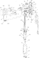
FIG. 3 is an exploded view of the electronic circulator cooker;
FIG. 4 is an exploded view of the wheel control device;
FIG. 5 is an exploded view of the components shown in the right side of FIG. 3;
FIG. 6 is a side elevation of FIG. 1; and
FIG. 7 is a rear view of FIG. 1.
DETAILED DESCRIPTION OF THE INVENTION
Referring to FIGS. 1 to 7, a sous-vide immersion electronic circulator cooker in accordance with the invention comprises the following components as discussed in detail below.
A casing 1 includes a front shell 11 and a rear shell 12 detachably secured to the front shell 11 as detailed below. The casing 1 has a bottom opening. The front shell 11 includes a window 111, two spaced recesses 112 on a lower end, a groove 113 on an inner surface, the groove 113 being above and adjacent to the recesses 112, a circuit board 114 secured to the window 111, a panel display 115 also secured to the window 111, a plurality light guide members 116 electrically connected to the circuit board 114, and a transparent touchscreen 117 secured to the window 111 and spaced from the circuit board 114.
The rear shell 12 includes a top opening 121, a plurality of lower openings 122, a plurality of upper openings 123, a mount member 124 secured to an outer surface, two spaced recesses 125 on a lower end, and a groove 126 on an inner surface, the groove 126 being above and adjacent to the recesses 125.
Within the casing 1 there are provided a wheel control device 13, a temperature limiting thermostat 14, a circuit board 15 for controlling switch, a fan mount 16, a main circuit board 17, a drive source 18 for agitation and testing, and a support 19 for heating member.
The wheel control device 13 includes a seat 131, a wheel 132 disposed in the seat 131, and a hollow fastening member 133 secured to the seat 131 with the wheel 132 projecting out of its open top and further projecting out of the top opening 121. The temperature limiting thermostat 14 functions to limit temperature to a desired range. The temperature limiting thermostat 14 includes a temperature probe 141 electrically connected to the temperature limiting thermostat 14.
The circuit board 15 for controlling switch is electrically connected to a wire 5 which is in turn configured to connect to an outlet. A mechanical fan 161 is mounted on the fan mount 16 for drawing cold air from the lower openings 122 and expelling hot air out of the casing 1 via the upper openings 123. The main circuit board 17 acts to activate heating and agitation. The drive source 18 for agitation and testing includes a motor 181, a motor shaft 182 extending downward from the motor 181, and two probes 183 for sensing temperature and for measuring water level respectively. The support 19 for heating member is provided on a bottom of the casing 1 and includes an annular flange 191 positioned in the grooves 113, 126 to seal the bottom of the casing 1, and an electric heating member 192 extending downward from the flange 191. The motor shaft 182, the probes 183 for sensing temperature and for measuring water level, and the temperature probe 141 of the temperature limiting thermostat 14 pass the support 19 for heating member to be proximate the electric heating member 192. A fan blade assembly 184 is fastened at a bottom end of the motor shaft 182. A cable tie 193 is provided to fasten the temperature probe 141 and the electric heating member 192 together so that the temperature probe 141 may measure the temperature of the electric heating member 192. A ground 194 has one end connected to the electric heating member 192.
The hollow cylindrical lower case section 2 has an open top and is configured to store a quantity of liquid. The lower case section 2 includes four equally spaced projections 21 on an inner surface configured to dispose in the recesses 112 and 125 for fasten the casing 1 and the lower case section 2 together. The lower case section 2 further comprises a vertical opening 22 for flowing liquid off, and a plurality of horizontal openings 23 adjacent to the bottom for flowing liquid off. An inlet device 3 includes a plurality of inlets 31 for flowing water in, and a rib 32 on an outer surface. A fastening assembly 4 includes a resilient member 41, an anti slip sleeve 42 put on a lower portion of the fastening assembly 4 and secured to the lower case section 2, and a cover 43 secured to the mount member 124 by pressing an upper portion of the fastening assembly 4 and the resilient member 41 against the back of the mount member 124. An AC (alternating current) power cord 5 has one end passing through the cover 43 to electrically connect to the main circuit board 17 for supplying power thereto. Consequently, power can be supplied from the main circuit board 17 to all electrical components of the invention. Further, the circuit board 114 is configured to control the main circuit board 17 for setting, operating, sensing, measurement, and information display.
While the invention has been described in terms of preferred embodiments, those skilled in the art will recognize that the invention can be practiced with modifications within the spirit and scope of the appended claims.

Claims (1)

What is claimed is:
1. A circulator cooker comprising:
a casing comprising a front shell including a window, two spaced first recesses on a lower end, a first groove on an inner surface, the first groove being above and adjacent to the first recesses, a circuit board secured to the window, a panel display secured to the window, a plurality of light guide members electrically connected to the circuit board, and a transparent touchscreen secured to the window and spaced from the circuit board; and a rear shell including a top opening, a plurality of lower openings, a plurality of upper openings, a mount member secured to an outer surface, two spaced second recesses on a lower end, and a second groove on an inner surface, the second groove being above and adjacent to the second recesses;
a wheel control device disposed in the casing and including a seat, a wheel disposed in the seat, and a hollow fastening member secured to the seat so that the wheel projects out of the top opening;
a temperature limiting thermostat disposed in the casing and including a temperature probe;
a controlling switch circuit board;
a mechanical fan for drawing cold air from outside the lower openings and expelling hot air out of the casing via the upper openings;
a drive source for agitation and testing disposed in the casing and including a motor, a motor shaft extending downward from the motor, and two probes for sensing temperature and for measuring water level respectively;
a main circuit board disposed in the casing and configured to activate heating and agitation;
an electric heating member disposed in the casing and extending downward from the flange wherein the motor shaft, the probes for sensing temperature and for measuring water level, and the temperature probe pass the support for heating member to be proximate the electric heating member;
a support for the electric heating member disposed on a bottom of the casing and including an annular flange positioned in the first and second grooves seal the bottom of the casing;
a fan blade assembly fastened at a bottom end of the motor shaft wherein the temperature probe and the electric heating member are fastened together;
a ground having one end connected to the electric heating member;
a hollow, cylindrical lower case section configured to store a quantity of liquid which is configured to be agitated by the fan blade assembly, the lower case section including a plurality of spaced projections on an inner surface configured to dispose in the first and second recesses for fastening the casing and the lower case section together, a vertical opening configured to allow liquid to flow therethrough when the circulator cooker is immersed in liquid, and a plurality of horizontal openings configured to allow liquid to flow therethrough when the circulator cooker is immersed in liquid;
an inlet device connected to a lower end of the lower case section, the inlet device including a plurality of inlets configured to allow liquid to flow therethrough when the circulator cooker is immersed in liquid, and a rib formed on an outer surface;
a fastening assembly including a resilient member, an anti slip sleeve put on a lower portion of the fastening assembly and secured to the lower case section, and a cover secured to the mount member by pressing an upper portion of the fastening assembly and the resilient member against a back of the mount member; and
an AC (alternating current) power cord having one end passing through the cover to electrically connect to the main circuit board for supplying power thereto;
wherein the circuit board is configured to control the main circuit board.
US15/607,997 2017-05-30 2017-05-30 Sous-vide immersion electronic circulator cooker Active 2038-05-02 US10595662B2 (en)

Priority Applications (1)

Application Number Priority Date Filing Date Title
US15/607,997 US10595662B2 (en) 2017-05-30 2017-05-30 Sous-vide immersion electronic circulator cooker

Applications Claiming Priority (1)

Application Number Priority Date Filing Date Title
US15/607,997 US10595662B2 (en) 2017-05-30 2017-05-30 Sous-vide immersion electronic circulator cooker

Publications (2)

Publication Number Publication Date
US20180344069A1 US20180344069A1 (en) 2018-12-06
US10595662B2 true US10595662B2 (en) 2020-03-24

Family

ID=64458446

Family Applications (1)

Application Number Title Priority Date Filing Date
US15/607,997 Active 2038-05-02 US10595662B2 (en) 2017-05-30 2017-05-30 Sous-vide immersion electronic circulator cooker

Country Status (1)

Country Link
US (1) US10595662B2 (en)

Cited By (1)

* Cited by examiner, † Cited by third party
Publication number Priority date Publication date Assignee Title
USD891848S1 (en) 2018-01-03 2020-08-04 Anova Applied Electronics, Inc. Circulator cooker

Families Citing this family (8)

* Cited by examiner, † Cited by third party
Publication number Priority date Publication date Assignee Title
USD907751S1 (en) * 2017-02-08 2021-01-12 Perfect Union Co., Ltd. Portable boiling water heater
US10758075B2 (en) * 2017-12-15 2020-09-01 Shenzhen Chenbei Technology Co., Ltd. Thermal immersion circulator
CN209712520U (en) * 2018-09-27 2019-12-03 东莞市丰海金电器有限公司 A kind of intelligent low-temperature sous stick
USD914435S1 (en) * 2019-02-04 2021-03-30 Breville Pty Limited Cooking appliance
USD944586S1 (en) * 2019-07-29 2022-03-01 Seb Immersion heater
USD964797S1 (en) * 2020-10-29 2022-09-27 Breville Pty Limited Cooking appliance
USD962694S1 (en) * 2021-02-21 2022-09-06 Shenzhen Yingboweiye Technology Co., Ltd. Sous vide cooker
USD962695S1 (en) * 2021-02-21 2022-09-06 Shenzhen Yingboweiye Technology Co., Ltd. Sous vide cooker

Citations (4)

* Cited by examiner, † Cited by third party
Publication number Priority date Publication date Assignee Title
US20130220143A1 (en) * 2012-02-29 2013-08-29 Nomiku Inc. Apparatus and system for low-temperature cooking
US20160022085A1 (en) * 2013-02-14 2016-01-28 Jeff Wu Circulator cooker
US20160037956A1 (en) * 2013-02-14 2016-02-11 Jeff Wu Circulator cooker
US20160192801A1 (en) * 2015-01-02 2016-07-07 Jeff Wu Circulator cooker

Patent Citations (4)

* Cited by examiner, † Cited by third party
Publication number Priority date Publication date Assignee Title
US20130220143A1 (en) * 2012-02-29 2013-08-29 Nomiku Inc. Apparatus and system for low-temperature cooking
US20160022085A1 (en) * 2013-02-14 2016-01-28 Jeff Wu Circulator cooker
US20160037956A1 (en) * 2013-02-14 2016-02-11 Jeff Wu Circulator cooker
US20160192801A1 (en) * 2015-01-02 2016-07-07 Jeff Wu Circulator cooker

Cited By (2)

* Cited by examiner, † Cited by third party
Publication number Priority date Publication date Assignee Title
USD891848S1 (en) 2018-01-03 2020-08-04 Anova Applied Electronics, Inc. Circulator cooker
USD893239S1 (en) * 2018-01-03 2020-08-18 Anova Applied Electronics, Inc. Circulator cooker clamp

Also Published As

Publication number Publication date
US20180344069A1 (en) 2018-12-06

Similar Documents

Publication Publication Date Title
US10595662B2 (en) Sous-vide immersion electronic circulator cooker
US10117538B2 (en) Sous-vide cooker with image translation functionality
US5934181A (en) Cooking utensil comprising a sensor for measuring the temperature of this utensil
KR102138631B1 (en) Electric cooking apparatus having an air flow
US10136749B2 (en) Circulator cooker with alarm system
EP2592974B1 (en) Multi cooker
JP6062540B2 (en) Cooking apparatus, cooking pan, and cooking method
AU2015202983B2 (en) Sous-vide cooker with image translation functionality
CN111802898B (en) Vacuum low-temperature cooking device
US11022321B1 (en) Cooking appliance accessory and method of use
US10779674B2 (en) Double tube immersion electronic circulation cooking device
US10619860B2 (en) Range appliance and sensor assembly
CA2887277A1 (en) Programmable heating circulator
US20190208946A1 (en) Portable Sous Vide Cooking Appliance
EP3369290A1 (en) Cooking appliance and method
CN208822360U (en) Cooker
CN210124596U (en) Cooking utensil
CN208926021U (en) food processor
JP6690079B2 (en) Heating cooker
WO2015113050A2 (en) Combination cooker
CN208228819U (en) Upper cover temperature sensing device, upper cap assembly and cooking apparatus of cooking apparatus
KR20070062738A (en) An apparatus for making food with a separable screen-cover
CN211186820U (en) Multipurpose pot capable of accurately controlling temperature
CN214128190U (en) Lid assembly for cooking appliance and cooking appliance
USRE49267E1 (en) Circulator cooker with alarm system

Legal Events

Date Code Title Description
AS Assignment

Owner name: PUC PERFECT UNION CO., LTD., TAIWAN

Free format text: ASSIGNMENT OF ASSIGNORS INTEREST;ASSIGNOR:CHAN, CHING;REEL/FRAME:042630/0335

Effective date: 20170523

STPP Information on status: patent application and granting procedure in general

Free format text: DOCKETED NEW CASE - READY FOR EXAMINATION

STPP Information on status: patent application and granting procedure in general

Free format text: NON FINAL ACTION MAILED

STPP Information on status: patent application and granting procedure in general

Free format text: RESPONSE TO NON-FINAL OFFICE ACTION ENTERED AND FORWARDED TO EXAMINER

STPP Information on status: patent application and granting procedure in general

Free format text: NOTICE OF ALLOWANCE MAILED -- APPLICATION RECEIVED IN OFFICE OF PUBLICATIONS

STPP Information on status: patent application and granting procedure in general

Free format text: PUBLICATIONS -- ISSUE FEE PAYMENT VERIFIED

STCF Information on status: patent grant

Free format text: PATENTED CASE

MAFP Maintenance fee payment

Free format text: PAYMENT OF MAINTENANCE FEE, 4TH YR, SMALL ENTITY (ORIGINAL EVENT CODE: M2551); ENTITY STATUS OF PATENT OWNER: SMALL ENTITY

Year of fee payment: 4