US10595387B2 - Driveless LED fixture - Google Patents
Driveless LED fixture Download PDFInfo
- Publication number
- US10595387B2 US10595387B2 US16/261,932 US201916261932A US10595387B2 US 10595387 B2 US10595387 B2 US 10595387B2 US 201916261932 A US201916261932 A US 201916261932A US 10595387 B2 US10595387 B2 US 10595387B2
- Authority
- US
- United States
- Prior art keywords
- fixtures
- power
- led
- leds
- power unit
- Prior art date
- Legal status (The legal status is an assumption and is not a legal conclusion. Google has not performed a legal analysis and makes no representation as to the accuracy of the status listed.)
- Active
Links
- 238000003491 array Methods 0.000 claims 2
- 235000015067 sauces Nutrition 0.000 abstract 1
- 238000010586 diagram Methods 0.000 description 9
- 238000006243 chemical reaction Methods 0.000 description 4
- 238000000034 method Methods 0.000 description 4
- 238000009434 installation Methods 0.000 description 2
- 230000001105 regulatory effect Effects 0.000 description 2
- 235000007688 Lycopersicon esculentum Nutrition 0.000 description 1
- 240000003768 Solanum lycopersicum Species 0.000 description 1
- 230000003247 decreasing effect Effects 0.000 description 1
- 238000001914 filtration Methods 0.000 description 1
- 238000009413 insulation Methods 0.000 description 1
- 238000002955 isolation Methods 0.000 description 1
- 239000000463 material Substances 0.000 description 1
- 239000002184 metal Substances 0.000 description 1
- 238000012986 modification Methods 0.000 description 1
- 230000004048 modification Effects 0.000 description 1
- 230000001681 protective effect Effects 0.000 description 1
- 230000000153 supplemental effect Effects 0.000 description 1
- 230000001052 transient effect Effects 0.000 description 1
Images


Classifications
-
- H—ELECTRICITY
- H05—ELECTRIC TECHNIQUES NOT OTHERWISE PROVIDED FOR
- H05B—ELECTRIC HEATING; ELECTRIC LIGHT SOURCES NOT OTHERWISE PROVIDED FOR; CIRCUIT ARRANGEMENTS FOR ELECTRIC LIGHT SOURCES, IN GENERAL
- H05B45/00—Circuit arrangements for operating light-emitting diodes [LED]
-
- A—HUMAN NECESSITIES
- A01—AGRICULTURE; FORESTRY; ANIMAL HUSBANDRY; HUNTING; TRAPPING; FISHING
- A01G—HORTICULTURE; CULTIVATION OF VEGETABLES, FLOWERS, RICE, FRUIT, VINES, HOPS OR SEAWEED; FORESTRY; WATERING
- A01G9/00—Cultivation in receptacles, forcing-frames or greenhouses; Edging for beds, lawn or the like
- A01G9/24—Devices or systems for heating, ventilating, regulating temperature, illuminating, or watering, in greenhouses, forcing-frames, or the like
- A01G9/249—Lighting means
-
- A—HUMAN NECESSITIES
- A01—AGRICULTURE; FORESTRY; ANIMAL HUSBANDRY; HUNTING; TRAPPING; FISHING
- A01G—HORTICULTURE; CULTIVATION OF VEGETABLES, FLOWERS, RICE, FRUIT, VINES, HOPS OR SEAWEED; FORESTRY; WATERING
- A01G9/00—Cultivation in receptacles, forcing-frames or greenhouses; Edging for beds, lawn or the like
- A01G9/20—Forcing-frames; Lights, i.e. glass panels covering the forcing-frames
-
- H05B33/0815—
-
- H—ELECTRICITY
- H05—ELECTRIC TECHNIQUES NOT OTHERWISE PROVIDED FOR
- H05B—ELECTRIC HEATING; ELECTRIC LIGHT SOURCES NOT OTHERWISE PROVIDED FOR; CIRCUIT ARRANGEMENTS FOR ELECTRIC LIGHT SOURCES, IN GENERAL
- H05B45/00—Circuit arrangements for operating light-emitting diodes [LED]
- H05B45/30—Driver circuits
- H05B45/37—Converter circuits
-
- H—ELECTRICITY
- H05—ELECTRIC TECHNIQUES NOT OTHERWISE PROVIDED FOR
- H05B—ELECTRIC HEATING; ELECTRIC LIGHT SOURCES NOT OTHERWISE PROVIDED FOR; CIRCUIT ARRANGEMENTS FOR ELECTRIC LIGHT SOURCES, IN GENERAL
- H05B45/00—Circuit arrangements for operating light-emitting diodes [LED]
- H05B45/50—Circuit arrangements for operating light-emitting diodes [LED] responsive to malfunctions or undesirable behaviour of LEDs; responsive to LED life; Protective circuits
- H05B45/54—Circuit arrangements for operating light-emitting diodes [LED] responsive to malfunctions or undesirable behaviour of LEDs; responsive to LED life; Protective circuits in a series array of LEDs
-
- H—ELECTRICITY
- H05—ELECTRIC TECHNIQUES NOT OTHERWISE PROVIDED FOR
- H05B—ELECTRIC HEATING; ELECTRIC LIGHT SOURCES NOT OTHERWISE PROVIDED FOR; CIRCUIT ARRANGEMENTS FOR ELECTRIC LIGHT SOURCES, IN GENERAL
- H05B45/00—Circuit arrangements for operating light-emitting diodes [LED]
- H05B45/30—Driver circuits
- H05B45/36—Circuits for reducing or suppressing harmonics, ripples or electromagnetic interferences [EMI]
Definitions
- the present invention relates to groups of LED fixtures and, in particular, reducing the cost thereof by centralizing the AC-DC conversion and current control functions.
- LED fixtures comprises three major parts:
- LED diodes when mounted on metal clad boards they are often referred to as light modules or light engines
- the fixture can also include secondary optics or lenses.
- power from the power mains are specified at 480V, 60 Hz AC, Triple phase. As noted above, power needs to be supplied to individual fixtures of LEDs lights. The desired LEDs require 20V DC at 7.5 A and power to be current regulated and maintained steady at 7.5 A.
- a current method for accomplishing this utilizes individual drivers on each fixture—LED drivers that are connected to the main power line. Power electronics are required to convert AC to DC, step down the voltage and regulate the current to the LEDs. However, this requires expensive electronics for and power line wiring to each fixture.
- FIG. 2B a centralized AC-DC system with a step down power source is utilized.
- a number of fixtures are connected in parallel (for example 20 fixtures) and power is supplied using a large AC-DC power source that delivers 20V at 150 amps.
- 150 amps at 20 VDC requires large gauge wires (especially over the long distances in a greenhouse installation) which can significantly increase costs and suffer from major line losses, reducing efficiency.
- the large AC-DC power source is expensive and in the end may not deliver much savings over the current method noted above.
- some electronics are still required in each fixture to provide current regulation.
- What is desired is to provide a multi-LED fixture system wherein the LED fixtures are grouped and wherein the AC-DC conversion process and current control functions are centralized at a reduced cost.
- the present invention provides a LED fixture system wherein the fixtures (or luminaires) are segregated into groups of between 20-30, connected in series, and wherein a central power unit is utilized to centralize the AC-DC conversion and current control functions, thus reducing system cost by reducing the number of driver circuits required.
- a failed LED bypass circuit inside each fixture allows the system to function when one or more of the fixtures in the chain happen to fail open circuit ( FIG. 3 .)
- a centralized power source converts the AC power input to a DC between 300 and 500V. Current regulation is performed inside the centralized power source. Each central power unit can thus drive approximately 30 luminaires in series ( FIG. 2C ).
- a low-cost central power source is utilized without the necessity of individual LED driver for each fixture and without the need for an electrician to install an individual power box for each fixture.
- the line losses are minimum since the voltage is high and current relatively low, less than 15 amps.
- the system is such that up to 30% of the fixtures in the series can tail and the rest of the system will still operate.
- FIG. 1 illustrates a perspective view of a conventional LED grow system
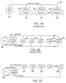
- FIG. 2A is a simplified block diagram of a prior art power distribution system that can be used in conjunction with the LED grow system shown in FIG. 1 ;
- FIG. 2B is a simplified block diagram of a possible power distribution system that could be utilized in the grow system of FIG. 1 ;
- FIG. 2C is a block/circuit diagram of the power distribution system of the present invention.
- FIG. 3 is a circuit diagram of the failed LED bypass circuit.
- FIG. 4 is a block diagram of the central power source.
- FIG. 1 is a simplified perspective view of a typical greenhouse 10 in which the power distribution system of the present invention can be utilized.
- Greenhouses, especially when located in the middle and high latitudes require supplemental artificial lighting in order to grow crops, such as tomatoes, year-round.
- FIG. 2A is a block diagram of a current method for providing power to a power distribution system 20 .
- System 20 is powered by a source 22 of 480 volts, 60 Hz AC which is coupled to a series of fixtures 24 and 26 and the last fixture 28 in a row via driver circuits 30 , 32 and 34 , respectively.
- FIG. 2B is a block diagram of a power distribution system that may be used in place of the system shown in FIG. 2A .
- a source of AC power 80 is coupled to step-down device 82 which provides 20 VDC and 150 amps to a series of LED fixtures 84 , 84 1 , 84 , . . . 84 n .
- the fixtures may contain some power electronics for current regulation. In this case, if each LED fixture requires 7.5 amps, 150 amps is sufficient for 20 fixtures.
- FIG. 2C illustrates a block diagram of a system in accordance with the teachings of the present invention.
- a source of AC power 90 is coupled to AC-DC converter 92 which generates 500 VDC, 7.5 amp output to a series of LED fixtures 95 , 95 1 , 95 2 , . . . 95 n as illustrated.
- the fixtures simply consist of LEDs mounted on a printed circuited board and coupled to a proper heat sink which can be the fixture housing.
- FIG. 3 illustrates a failed LED bypass circuit.
- the LED circuit board 50 contains several LEDs connected in series-parallel fashion as shown. LEDs normally fail open circuit. When one or more of the LEDs in each series fails the current will no longer pass to downstream fixtures in the system causing all fixtures in the system to shut down. The bypass circuit 51 will then trigger on, bypassing the LEDs on the failed fixture and allowing the remainder of the fixtures in the system to function as normal.
- FIG. 4 illustrates a block diagram of the central power unit.
- Three phase AC at 480V is applied to the unite 60 .
- Power goes through the EMI filter 61 and then through a bridge rectifier 62 to the main switch 63 .
- a transformer 64 provides galvanic isolation. Power from the transforms 64 is then rectified to DC via unit 65 and regulated through a feedback loop consisting of the reference or error amplifier 72 , an optocoupler 71 and a driver signal generator 70 .
- the power output of the Central Power Supply Unit appears at 66 and is constant DC 300 to 500V unit max current of 7.5 Amps.
- Total power 150 watts.
Landscapes
- Life Sciences & Earth Sciences (AREA)
- Environmental Sciences (AREA)
- Circuit Arrangement For Electric Light Sources In General (AREA)
Abstract
Description
-
- Length: Typically between 100 and 120 feet.
- Width: 20 feet per section width
- LED lights: 11,12,13 Multiple rows (3 shown) approximately 4 feet apart in length;
-
- Triple phase, 240 Volts
- Two phase, 480 Volts
- Two Phase, 240 Volts
Claims (3)
Priority Applications (1)
| Application Number | Priority Date | Filing Date | Title |
|---|---|---|---|
| US16/261,932 US10595387B2 (en) | 2017-12-18 | 2019-01-30 | Driveless LED fixture |
Applications Claiming Priority (2)
| Application Number | Priority Date | Filing Date | Title |
|---|---|---|---|
| US201715844958A | 2017-12-18 | 2017-12-18 | |
| US16/261,932 US10595387B2 (en) | 2017-12-18 | 2019-01-30 | Driveless LED fixture |
Related Parent Applications (1)
| Application Number | Title | Priority Date | Filing Date |
|---|---|---|---|
| US201715844958A Continuation | 2017-12-18 | 2017-12-18 |
Publications (2)
| Publication Number | Publication Date |
|---|---|
| US20190191513A1 US20190191513A1 (en) | 2019-06-20 |
| US10595387B2 true US10595387B2 (en) | 2020-03-17 |
Family
ID=66816634
Family Applications (1)
| Application Number | Title | Priority Date | Filing Date |
|---|---|---|---|
| US16/261,932 Active US10595387B2 (en) | 2017-12-18 | 2019-01-30 | Driveless LED fixture |
Country Status (1)
| Country | Link |
|---|---|
| US (1) | US10595387B2 (en) |
Cited By (1)
| Publication number | Priority date | Publication date | Assignee | Title |
|---|---|---|---|---|
| EP4061097A1 (en) | 2021-03-16 | 2022-09-21 | George Mekhtarian | Lighting systems |
Citations (5)
| Publication number | Priority date | Publication date | Assignee | Title |
|---|---|---|---|---|
| US20050281030A1 (en) * | 2002-11-19 | 2005-12-22 | Denovo Lighting, Llc | Power controls with photosensor for tube mounted LEDs with ballast |
| US20100020536A1 (en) * | 2008-07-24 | 2010-01-28 | Bafetti Vincent H | Lighting system for growing plants |
| US20100060175A1 (en) * | 2008-09-09 | 2010-03-11 | Exclara Inc. | Apparatus, Method and System for Providing Power to Solid State Lighting |
| US20110209400A1 (en) * | 2007-08-15 | 2011-09-01 | Lemnis Lighting Patent Holding B.V. | Led lighting device for growing plants |
| US20130026925A1 (en) * | 2011-07-28 | 2013-01-31 | Ven Antony P Van De | Solid State Lighting Apparatus and Methods Using Integrated Driver Circuitry |
-
2019
- 2019-01-30 US US16/261,932 patent/US10595387B2/en active Active
Patent Citations (5)
| Publication number | Priority date | Publication date | Assignee | Title |
|---|---|---|---|---|
| US20050281030A1 (en) * | 2002-11-19 | 2005-12-22 | Denovo Lighting, Llc | Power controls with photosensor for tube mounted LEDs with ballast |
| US20110209400A1 (en) * | 2007-08-15 | 2011-09-01 | Lemnis Lighting Patent Holding B.V. | Led lighting device for growing plants |
| US20100020536A1 (en) * | 2008-07-24 | 2010-01-28 | Bafetti Vincent H | Lighting system for growing plants |
| US20100060175A1 (en) * | 2008-09-09 | 2010-03-11 | Exclara Inc. | Apparatus, Method and System for Providing Power to Solid State Lighting |
| US20130026925A1 (en) * | 2011-07-28 | 2013-01-31 | Ven Antony P Van De | Solid State Lighting Apparatus and Methods Using Integrated Driver Circuitry |
Cited By (1)
| Publication number | Priority date | Publication date | Assignee | Title |
|---|---|---|---|---|
| EP4061097A1 (en) | 2021-03-16 | 2022-09-21 | George Mekhtarian | Lighting systems |
Also Published As
| Publication number | Publication date |
|---|---|
| US20190191513A1 (en) | 2019-06-20 |
Similar Documents
| Publication | Publication Date | Title |
|---|---|---|
| US8436555B2 (en) | DC low voltage distribution box for indoor multi LEDs lamp | |
| US8493000B2 (en) | Method and system for driving light emitting elements | |
| RU2018135082A (en) | CONTROLLED POWER AND LIGHTING SYSTEM | |
| RU2697830C2 (en) | Driver circuit and excitation method | |
| CN103609199B (en) | LED array accessory power supply | |
| US10595387B2 (en) | Driveless LED fixture | |
| US9462648B2 (en) | Method and arrangement for remotely driving light emitting diodes from a three-phase power source via a single phase cable system | |
| US8912732B2 (en) | Current sensing for LED drivers | |
| WO2014088947A1 (en) | Dimmable led having constant voltage and linear current control using headroom control | |
| US10375795B2 (en) | Powering an auxiliary circuit associated with a luminaire | |
| EP3105993B1 (en) | Lighting system comprising a protection circuit, and corresponding method for protecting light sources from electrostatic discharges | |
| KR20160077718A (en) | Led lighting apparatus for three phase ac and led lighting system comprising the same | |
| US20220183126A1 (en) | Driveless led fixture | |
| US20110025213A1 (en) | Wisdom tech led current balance assembly | |
| US11606848B2 (en) | Lighting systems | |
| GB2536300A (en) | Integrated light source module and housing therefore | |
| WO2015038026A1 (en) | Led light | |
| EP4562341B1 (en) | A track lighting system comprising a lighting track to which fixtures may be connected for providing light as well as a corresponding lighting fixture | |
| US12058788B2 (en) | AC LED circuit with standard dimmer compatibility | |
| WO2017200424A1 (en) | Led light source powered by an unstable three-phase ac network | |
| EP2859781B1 (en) | Led lighting system remotely distributed power network | |
| KR20250136343A (en) | Aircraft electrical power system and method for regulating and supplying voltage to power fluctuations of stationary aircraft | |
| JP6854443B2 (en) | Lighting device and lighting equipment | |
| JP3197422U (en) | Power supply system and power system | |
| KR101383143B1 (en) | Luminous device |
Legal Events
| Date | Code | Title | Description |
|---|---|---|---|
| FEPP | Fee payment procedure |
Free format text: ENTITY STATUS SET TO UNDISCOUNTED (ORIGINAL EVENT CODE: BIG.); ENTITY STATUS OF PATENT OWNER: SMALL ENTITY |
|
| FEPP | Fee payment procedure |
Free format text: ENTITY STATUS SET TO SMALL (ORIGINAL EVENT CODE: SMAL); ENTITY STATUS OF PATENT OWNER: SMALL ENTITY |
|
| STPP | Information on status: patent application and granting procedure in general |
Free format text: RESPONSE TO NON-FINAL OFFICE ACTION ENTERED AND FORWARDED TO EXAMINER |
|
| STPP | Information on status: patent application and granting procedure in general |
Free format text: FINAL REJECTION MAILED |
|
| STPP | Information on status: patent application and granting procedure in general |
Free format text: RESPONSE AFTER FINAL ACTION FORWARDED TO EXAMINER |
|
| STPP | Information on status: patent application and granting procedure in general |
Free format text: ADVISORY ACTION MAILED |
|
| STPP | Information on status: patent application and granting procedure in general |
Free format text: RESPONSE AFTER FINAL ACTION FORWARDED TO EXAMINER |
|
| STPP | Information on status: patent application and granting procedure in general |
Free format text: NOTICE OF ALLOWANCE MAILED -- APPLICATION RECEIVED IN OFFICE OF PUBLICATIONS |
|
| STPP | Information on status: patent application and granting procedure in general |
Free format text: PUBLICATIONS -- ISSUE FEE PAYMENT VERIFIED |
|
| STCF | Information on status: patent grant |
Free format text: PATENTED CASE |
|
| FEPP | Fee payment procedure |
Free format text: MAINTENANCE FEE REMINDER MAILED (ORIGINAL EVENT CODE: REM.); ENTITY STATUS OF PATENT OWNER: SMALL ENTITY |
|
| FEPP | Fee payment procedure |
Free format text: SURCHARGE FOR LATE PAYMENT, SMALL ENTITY (ORIGINAL EVENT CODE: M2554); ENTITY STATUS OF PATENT OWNER: SMALL ENTITY |
|
| MAFP | Maintenance fee payment |
Free format text: PAYMENT OF MAINTENANCE FEE, 4TH YR, SMALL ENTITY (ORIGINAL EVENT CODE: M2551); ENTITY STATUS OF PATENT OWNER: SMALL ENTITY Year of fee payment: 4 |