US10594141B2 - Soft magnetic alloy, wireless power transmitting apparatus, and wireless power receiving apparatus including the same - Google Patents
Soft magnetic alloy, wireless power transmitting apparatus, and wireless power receiving apparatus including the same Download PDFInfo
- Publication number
- US10594141B2 US10594141B2 US14/943,286 US201514943286A US10594141B2 US 10594141 B2 US10594141 B2 US 10594141B2 US 201514943286 A US201514943286 A US 201514943286A US 10594141 B2 US10594141 B2 US 10594141B2
- Authority
- US
- United States
- Prior art keywords
- soft magnetic
- magnetic alloy
- wireless power
- present
- range
- Prior art date
- Legal status (The legal status is an assumption and is not a legal conclusion. Google has not performed a legal analysis and makes no representation as to the accuracy of the status listed.)
- Active, expires
Links
Images


Classifications
-
- H02J5/005—
-
- C—CHEMISTRY; METALLURGY
- C22—METALLURGY; FERROUS OR NON-FERROUS ALLOYS; TREATMENT OF ALLOYS OR NON-FERROUS METALS
- C22C—ALLOYS
- C22C38/00—Ferrous alloys, e.g. steel alloys
- C22C38/06—Ferrous alloys, e.g. steel alloys containing aluminium
-
- H—ELECTRICITY
- H02—GENERATION; CONVERSION OR DISTRIBUTION OF ELECTRIC POWER
- H02J—ELECTRIC POWER NETWORKS; CIRCUIT ARRANGEMENTS OR SYSTEMS FOR SUPPLYING OR DISTRIBUTING ELECTRIC POWER; SYSTEMS FOR STORING ELECTRIC ENERGY
- H02J50/00—Circuit arrangements or systems for wireless supply or distribution of electric power
- H02J50/10—Circuit arrangements or systems for wireless supply or distribution of electric power using inductive coupling
- H02J50/12—Circuit arrangements or systems for wireless supply or distribution of electric power using inductive coupling of the resonant type
-
- C—CHEMISTRY; METALLURGY
- C21—METALLURGY OF IRON
- C21D—MODIFYING THE PHYSICAL STRUCTURE OF FERROUS METALS; GENERAL DEVICES FOR HEAT TREATMENT OF FERROUS OR NON-FERROUS METALS OR ALLOYS; MAKING METAL MALLEABLE, e.g. BY DECARBURISATION OR TEMPERING
- C21D8/00—Modifying the physical properties of ferrous metals or ferrous alloys by deformation combined with, or followed by, heat treatment
-
- C—CHEMISTRY; METALLURGY
- C22—METALLURGY; FERROUS OR NON-FERROUS ALLOYS; TREATMENT OF ALLOYS OR NON-FERROUS METALS
- C22C—ALLOYS
- C22C38/00—Ferrous alloys, e.g. steel alloys
- C22C38/002—Ferrous alloys, e.g. steel alloys containing In, Mg, or other elements not provided for in one single group C22C38/001 - C22C38/60
-
- C—CHEMISTRY; METALLURGY
- C22—METALLURGY; FERROUS OR NON-FERROUS ALLOYS; TREATMENT OF ALLOYS OR NON-FERROUS METALS
- C22C—ALLOYS
- C22C38/00—Ferrous alloys, e.g. steel alloys
- C22C38/005—Ferrous alloys, e.g. steel alloys containing rare earths, i.e. Sc, Y, Lanthanides
-
- C—CHEMISTRY; METALLURGY
- C22—METALLURGY; FERROUS OR NON-FERROUS ALLOYS; TREATMENT OF ALLOYS OR NON-FERROUS METALS
- C22C—ALLOYS
- C22C38/00—Ferrous alloys, e.g. steel alloys
- C22C38/02—Ferrous alloys, e.g. steel alloys containing silicon
-
- C—CHEMISTRY; METALLURGY
- C22—METALLURGY; FERROUS OR NON-FERROUS ALLOYS; TREATMENT OF ALLOYS OR NON-FERROUS METALS
- C22C—ALLOYS
- C22C45/00—Amorphous alloys
- C22C45/02—Amorphous alloys with iron as the major constituent
-
- H—ELECTRICITY
- H01—ELECTRIC ELEMENTS
- H01F—MAGNETS; INDUCTANCES; TRANSFORMERS; SELECTION OF MATERIALS FOR THEIR MAGNETIC PROPERTIES
- H01F1/00—Magnets or magnetic bodies characterised by the magnetic materials therefor; Selection of materials for their magnetic properties
- H01F1/01—Magnets or magnetic bodies characterised by the magnetic materials therefor; Selection of materials for their magnetic properties of inorganic materials
- H01F1/03—Magnets or magnetic bodies characterised by the magnetic materials therefor; Selection of materials for their magnetic properties of inorganic materials characterised by their coercivity
- H01F1/12—Magnets or magnetic bodies characterised by the magnetic materials therefor; Selection of materials for their magnetic properties of inorganic materials characterised by their coercivity of soft-magnetic materials
- H01F1/14—Magnets or magnetic bodies characterised by the magnetic materials therefor; Selection of materials for their magnetic properties of inorganic materials characterised by their coercivity of soft-magnetic materials metals or alloys
- H01F1/147—Alloys characterised by their composition
- H01F1/14766—Fe-Si based alloys
- H01F1/14791—Fe-Si-Al based alloys, e.g. Sendust
-
- H—ELECTRICITY
- H01—ELECTRIC ELEMENTS
- H01F—MAGNETS; INDUCTANCES; TRANSFORMERS; SELECTION OF MATERIALS FOR THEIR MAGNETIC PROPERTIES
- H01F1/00—Magnets or magnetic bodies characterised by the magnetic materials therefor; Selection of materials for their magnetic properties
- H01F1/01—Magnets or magnetic bodies characterised by the magnetic materials therefor; Selection of materials for their magnetic properties of inorganic materials
- H01F1/03—Magnets or magnetic bodies characterised by the magnetic materials therefor; Selection of materials for their magnetic properties of inorganic materials characterised by their coercivity
- H01F1/12—Magnets or magnetic bodies characterised by the magnetic materials therefor; Selection of materials for their magnetic properties of inorganic materials characterised by their coercivity of soft-magnetic materials
- H01F1/14—Magnets or magnetic bodies characterised by the magnetic materials therefor; Selection of materials for their magnetic properties of inorganic materials characterised by their coercivity of soft-magnetic materials metals or alloys
- H01F1/147—Alloys characterised by their composition
- H01F1/153—Amorphous metallic alloys, e.g. glassy metals
- H01F1/15308—Amorphous metallic alloys, e.g. glassy metals based on Fe/Ni
-
- H—ELECTRICITY
- H01—ELECTRIC ELEMENTS
- H01F—MAGNETS; INDUCTANCES; TRANSFORMERS; SELECTION OF MATERIALS FOR THEIR MAGNETIC PROPERTIES
- H01F38/00—Adaptations of transformers or inductances for specific applications or functions
- H01F38/14—Inductive couplings
-
- H—ELECTRICITY
- H02—GENERATION; CONVERSION OR DISTRIBUTION OF ELECTRIC POWER
- H02J—ELECTRIC POWER NETWORKS; CIRCUIT ARRANGEMENTS OR SYSTEMS FOR SUPPLYING OR DISTRIBUTING ELECTRIC POWER; SYSTEMS FOR STORING ELECTRIC ENERGY
- H02J50/00—Circuit arrangements or systems for wireless supply or distribution of electric power
- H02J50/005—Mechanical details of housing or structure aiming to accommodate the power transfer means, e.g. mechanical integration of coils, antennas or transducers into emitting or receiving devices
-
- H—ELECTRICITY
- H02—GENERATION; CONVERSION OR DISTRIBUTION OF ELECTRIC POWER
- H02J—ELECTRIC POWER NETWORKS; CIRCUIT ARRANGEMENTS OR SYSTEMS FOR SUPPLYING OR DISTRIBUTING ELECTRIC POWER; SYSTEMS FOR STORING ELECTRIC ENERGY
- H02J50/00—Circuit arrangements or systems for wireless supply or distribution of electric power
- H02J50/10—Circuit arrangements or systems for wireless supply or distribution of electric power using inductive coupling
-
- H02J7/025—
-
- C—CHEMISTRY; METALLURGY
- C22—METALLURGY; FERROUS OR NON-FERROUS ALLOYS; TREATMENT OF ALLOYS OR NON-FERROUS METALS
- C22C—ALLOYS
- C22C2200/00—Crystalline structure
- C22C2200/02—Amorphous
-
- C—CHEMISTRY; METALLURGY
- C22—METALLURGY; FERROUS OR NON-FERROUS ALLOYS; TREATMENT OF ALLOYS OR NON-FERROUS METALS
- C22C—ALLOYS
- C22C2202/00—Physical properties
- C22C2202/02—Magnetic
Definitions
- the present invention relates to a soft magnetic alloy and, more specifically, to a soft magnetic alloy used in electric transformers, pulse generators, compressions, electric chokes, energy-accumulating inductors, magnetic sensors, or the like, and a wireless power transmitting apparatus and wireless power receiving apparatus including the soft magnetic alloy.
- a wireless power transmitting apparatus is connected to a power source, and includes a metal substrate, a soft magnetic sheet disposed on the metal substrate, and a transmission coil disposed on the soft magnetic sheet.
- a wireless power receiving apparatus is connected to a load, and includes a soft magnetic sheet and a reception coil disposed on the soft magnetic sheet.
- the soft magnetic sheet of the wireless power transmitting apparatus, and the soft magnetic sheet of the wireless power receiving apparatus may shield electromagnetic waves radiated from the transmission coil and electromagnetic waves received by the reception coil, respectively. Accordingly, an energy loss occurring between the wireless power transmitting apparatus and the wireless power receiving apparatus may be minimized, and a power transmitting and receiving efficiency may be improved.
- Fe-based soft magnetic alloys may be used as shielding materials.
- the Fe-based soft magnetic alloys may be classified into, for example, an Fe—Si soft magnetic alloy, an amorphous soft magnetic alloy, and a nanocrystal soft magnetic alloy, etc.
- the Fe—Si soft magnetic alloy may be usable at a low frequency band of about 10 kHz since it has a low resistivity, although it has a high saturated magnetic flux density in the range of 1.5 T to 1.9 T. Accordingly, the Fe—Si soft magnetic alloy may not be applicable to a wireless charging system using a frequency band in the range of 110 to 250 kHz.
- the amorphous soft magnetic alloy or nanocrystal soft magnetic alloy including Fe, a ferromagnetic element, and a metalloid element may be used at a frequency band in the range of 110 to 250 kHz.
- the soft magnetic alloy including Fe and a metalloid element has a low saturated magnetic flux density of 1.56 T or less, it is difficult to be thinned and manufacturing costs thereof may increase.
- the present invention is directed to an Fe-based soft magnetic alloy having a high saturated magnetic flux density, a low AC magnetic loss, and a high magnetic stability at an operating temperature, and a wireless power transmitting apparatus and wireless power receiving apparatus including the soft magnetic alloy.
- a soft magnetic alloy has a composition expressed by a Formula below.
- the X and Y represent metalloid elements, and a content of the metalloid elements is in the range of 9 to 15.5 at %.
- the metalloid elements may include at least one of B, C, Al, Si, P, Ga, and Ge.
- the X may include B, and the Y may include Si.
- the a may be in the range of 84.5 to 91.2 at %
- the b may be in the range of 2.0 to 9.0 at %
- the c may be in the range of 3.0 to 12.0 at %.
- the amount of saturated magnetic induction of the soft magnetic alloy may be 1.7 T or more, and a resistivity of the soft magnetic alloy may be 30 ⁇ cm or more.
- the soft magnetic alloy may be thermally treated by annealing at a temperature between 350° C. and 400° C.
- a wireless power transmitting apparatus of a wireless charging system includes a soft magnetic sheet and a transmission coil formed on the soft magnetic sheet.
- the soft magnetic sheet includes a soft magnetic alloy having a composition expressed by a Formula below. Fe a X b Y c [Formula]
- the X and Y represent metalloid elements, and a content of the metalloid elements is in the range of 9 to 15.5 at %.
- a wireless power transmitting apparatus of a wireless charging system includes a soft magnetic sheet and a reception coil formed on the soft magnetic sheet.
- the soft magnetic sheet includes a soft magnetic alloy having a composition expressed by a Formula below. Fe a X b Y c [Formula]
- the X and Y represent metalloid elements, and a content of the metalloid elements is in the range of 9 to 15.5 at %.
- FIG. 1 is a graph illustrating saturated magnetization of a soft magnetic alloy according to an embodiment of the present invention and saturated magnetization of a normal soft magnetic alloy;
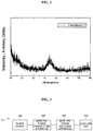
- FIG. 2 is an XRD analysis graph of a soft magnetic alloy according to an embodiment of the present invention.
- FIG. 3 illustrates a wireless charging system according to an embodiment of the present invention
- FIG. 4 illustrates a method of wirelessly transmitting and receiving power in a wireless charging system according to an embodiment of the present invention
- FIG. 5 illustrates a portion of a wireless power transmitting apparatus according to an embodiment of the present invention.
- FIG. 6 illustrates a portion of a wireless power receiving apparatus according to an embodiment of the present invention.
- a soft magnetic alloy according to an embodiment of the present invention may be expressed by a general formula Fe a X b Y c , and compositions thereof may be 84.5 ⁇ a ⁇ 91.0, 2 ⁇ b ⁇ 9, 3.0 ⁇ c ⁇ 12.0, and 9.0 ⁇ b+c ⁇ 15.5, in terms of atomic percentages.
- X and Y represent metalloid elements.
- iron (Fe) is an essential element in charge of expressing magnetic properties.
- an iron content is less than 84.5 at %, a saturated magnetic flux density or a glass-forming ability of the soft magnetic alloy may be degraded.
- the iron content in the soft magnetic alloy according to the embodiment of the present invention may be 84.5 at % or more.
- the iron content in the soft magnetic alloy according to the embodiment of the present invention may be 91.0 at % or less.
- the metalloid elements may include at least one of B, C, Al, Si, P, Ga, and Ge.
- a total content of the metalloid elements in the soft magnetic alloy according to the embodiment of the present invention is less than 9.0 at %, the glass-forming ability may be degraded due to a lack of glass-forming elements.
- the glass-forming ability may be degraded due to an excess of glass-forming elements, and the saturated magnetic flux density may decrease since a relative content of iron decreases.
- the content of the metalloid elements in the soft magnetic alloy according to the embodiment of the present invention may be in the range of 9.0 at % to 15.5 at %. Accordingly, since the content of the metalloid elements in the soft magnetic alloy according to the embodiment of the present invention is lower than that in a normal soft magnetic alloy, plastic deformation of a spherical powder may be available, and thus the soft magnetic alloy may be easily processed into a flake form and a ribbon form.
- the soft magnetic alloy according to the embodiment of the present invention since occupancy of a magnetic material in the soft magnetic alloy increases depending on the number of stacks and the number of windings, or by reducing spaces between layers, an effective saturated magnetic flux density may increase. Further, the soft magnetic alloy according to the embodiment of the present invention may have a high iron content and a high saturated magnetic flux density. Due to the high saturated magnetic flux density, when the soft magnetic alloy according to the embodiment of the present invention is used as a magnetic component of a transformer, an inductor, a noise filter, or a motor, size reduction thereof may be expected and overall costs of raw materials may be reduced due to an increase in the content of Fe, which is an inexpensive element.
- the soft magnetic alloy according to the embodiment of the present invention since the soft magnetic alloy according to the embodiment of the present invention has a high glass-forming ability and the high saturated magnetic flux density at the same time, an amorphous bulk material having an amorphous structure may be fabricated therefrom. Accordingly, the soft magnetic alloy according to the embodiment of the present invention may be fabricated in the form of a ribbon or powder having a spherical or flake shape to be used in a magnetic core, or may be mixed with a resin or and casted in the form of a sheet to be used in a wireless power transmitting and receiving apparatus.
- the metalloid element X is boron (B), and the metalloid element Y is silicon (Si).
- the soft magnetic alloy according to the embodiment of the present invention may include boron at 9.65 at % or more and 22 at % or less.
- the soft magnetic alloy according to the embodiment of the present invention may include Si at 3.0 at % or more and 12.0 at % or less.
- the soft magnetic alloys according to Examples 1 to 9 have saturated magnetic flux densities of 1.7 T or more, and resistivity of 30 ⁇ cm or more.
- the soft magnetic alloys according to Examples and Comparative Examples of Table 1 were fabricated by dissolving metal powder having respective compositions at 1700° C., cooling the dissolved metal power to room temperature using a water quenching process, forming spherical powder using a gas atomizer, and fabricating flakes by performing a heat treatment on the spherical powder at a temperature in the range of 350° C. to 400° C.
- the saturated magnetic flux density is 1.7 T or less when an iron content is 82 at % and a content of the metalloid element is 18 at %, while the saturated magnetic flux density is more than 1.7 T when the iron content is in a range of 84.5 to 91.0 at % and the content of the metalloid element is in a range of 9.1 to 15.5 at %.
- the resistivity of the soft magnetic alloys in Examples 1 to 4 is 30 ⁇ cm or more.
- the resistivity is 30 ⁇ cm or less when the iron content is 93 at % and the content of the metalloid element is 7.0 at %, while the resistivity is more than 30 ⁇ cm when the iron content is in the range of 86.0 to 88.0 at % and the content of metalloid element is in the range of 12.0 to 14.0 at %.
- the saturated magnetic flux density of the soft magnetic alloys in Examples 5 to 9 are 1.7 T or more.
- FIG. 1 is a graph illustrating saturated magnetization of the soft magnetic alloy according to an embodiment of the present invention and saturated magnetization of a normal soft magnetic alloy.
- the saturated magnetization of an Fe 82 B 10.5 Si 7.5 soft magnetic alloy according to Comparative Example 1 is compared with that of an Fe 88 B 7.0 Si 5.0 soft magnetic alloy according to Example 3. It is shown that the soft magnetic alloy according to Example 3 has a higher level of saturated magnetization than the soft magnetic alloy according to Comparative Example 1.
- the saturated magnetization is an inherent property of a material, and indicates how strong a magnetism of a material is.
- T is a saturated magnetic flux density
- ⁇ is a density of a soft magnetic alloy powder
- M is saturated magnetization
- FIG. 2 is an XRD analysis graph of a soft magnetic alloy according to an embodiment of the present invention.
- FIG. 2 illustrates distributions of relative elements. It can be seen through a uniform elemental density distribution that glass performance characteristics were improved. Accordingly, the soft magnetic alloy according to the embodiment of the present invention may have a high saturated magnetic flux density, and may be easily processed into flakes.
- the soft magnetic alloy according to the embodiment of the present invention can be used in a frequency band in the range of 110 kHz to 250 kHz, it may be suitable for a wireless power transmitting apparatus or a wireless power receiving apparatus of a wireless charging system.
- FIG. 3 illustrates a wireless charging system according to an embodiment of the present invention.
- a wireless charging system 10 may include a power source 100 , a wireless power transmitting apparatus 200 , a wireless power receiving apparatus 300 , and a load line unit 400 .
- the wireless power transmitting apparatus 200 is connected to the power source 100 and receives power from the power source 100 .
- the wireless power transmitting apparatus 200 may wirelessly transmit power to the wireless power receiving apparatus 300 .
- the wireless power transmitting apparatus 200 may transmit power by an electromagnetic induction method process or a resonance method.
- the power source 100 and the wireless power transmitting apparatus 200 are illustrated as separated components from each other in FIG. 3 , but are not limited thereto.
- the power source 100 may be included in the wireless power transmitting apparatus 200 .
- the wireless power receiving apparatus 300 receives power from the wireless power transmitting apparatus 200 .
- the wireless power receiving apparatus 300 may receive power by the electromagnetic induction method or the resonance method, too.
- the wireless power receiving apparatus 300 may supply the received power to the load line unit 400 .
- the load line unit 400 may be a battery or a device in which a battery is built-in.
- the load line unit 400 and the wireless power receiving apparatus 300 are illustrated as separated components from each other in FIG. 3 , but are not limited thereto.
- the load line unit 400 may be included in the wireless power receiving apparatus 300 .
- FIG. 4 illustrates a method of wirelessly transmitting and receiving power in a wireless charging system according to an embodiment of the present invention.
- a wireless power transmitting apparatus 200 may include a transmission coil 210 .
- a wireless power receiving apparatus 300 may include a reception coil 310 and a rectifying unit 320 .
- the power source 100 may generate AC power having a predetermined frequency and transmit it to the transmission coil 210 of the wireless power transmitting apparatus 200 .
- AC currents generated in the transmission coil 210 may be transmitted to the reception coil 310 inductively coupled to the transmission coil 210 .
- the AC power transmitted to the transmission coil 210 may be transmitted to the wireless power receiving apparatus 300 having the same resonance frequency as the wireless power transmitting apparatus 200 by a frequency resonance method.
- the power may be transmitted between two LC circuits having matched impedance by the frequency resonance method.
- the power transmitted to the reception coil 310 by the electromagnetic induction method or the resonance method may be rectified by the rectifying unit 320 and transmitted to the load line unit 400 .
- FIG. 5 illustrates a portion of a wireless power transmitting apparatus according to an embodiment of the present invention
- FIG. 6 illustrates a portion of a wireless power receiving apparatus according to an embodiment of the present invention.
- a wireless power transmitting apparatus 1200 may include a soft magnetic sheet 1210 and a transmission coil 1220 .
- the soft magnetic sheet 1210 may be formed of a soft magnetic material having a thickness of several millimeters.
- the transmission coil 1220 may be disposed on the soft magnetic sheet 1210 .
- a permanent magnet may be further disposed on the soft magnetic sheet 1210 .
- the permanent magnet may be surrounded by the transmission coil 1220 .
- a wireless power receiving apparatus 1300 may include a soft magnetic substrate 1310 and a reception coil 1320 , and the reception coil 1320 may be disposed on the soft magnetic substrate 1310 .
- the reception coil 1320 may be formed in a coil plane wound in a direction parallel to the soft magnetic substrate 1310 on the soft magnetic substrate 1310 .
- an NFC coil may be further disposed on the soft magnetic substrate 1310 .
- the NFC coil may be formed to surround an outer side of the reception coil 1320 .
- At least one of the soft magnetic sheet 1210 of the wireless power transmitting apparatus 1200 and the soft magnetic substrate 1310 of the wireless power receiving apparatus 1300 includes a soft magnetic alloy having Formula 1.
- X and Y represent metalloid elements, and may include at least one of B, C, Al, Si, P, Ga, and Ge.
- X includes boron (B)
- Y includes silicon (Si).
- a may be in the range of 84.5 to 91.2 at %
- b may be in the range of 2.0 to 9.0 at %
- c may be in the range of 3.0 to 12.0 at %.
- the resistivity of the soft magnetic alloy may decrease to 30 ⁇ cm or less, and the coercivity of the soft magnetic alloy may increase to 40 Oe or more.
- the iron content is less than 84.5 at % and the metalloid content is more than 15.5 at %, there are problems in that the saturated magnetic flux density of the soft magnetic alloy may decrease to 1.7 T or less and the coercivity of the soft magnetic alloy may increase to 40 Oe or more.
- the resistivity decreases to 30 ⁇ cm or less, eddy current losses may increase in a frequency band of 100 kHz or more.
- the soft magnetic alloy having the resistivity of 30 ⁇ cm or less may not be suitable for the wireless charging system.
- the saturated magnetic flux density decreases to 1.7 T or less, it is difficult to form a thinned shielding material.
- the coercivity of the soft magnetic alloy increases to 40 Oe or more, the soft magnetic alloy may be difficult to be processed into flakes, resulting in lowering of a magnetic permeability in a planar direction.
- the iron content may be in the range of 84.5 to 91.2 at %, and the content of the metalloid element may be in the range of 9 to 15.5 at %.
- unit used in the embodiments of the present invention represents a hardware component including a field programmable gate array (FPGA) or an application specific integrated circuit (ASIC), and executes particular operations.
- FPGA field programmable gate array
- ASIC application specific integrated circuit
- the “unit” may be configured to be stored into an addressable storage device or may be configured to operate one or more processors.
- the “unit” may include software components, object oriented software components, class components, and task components. Further, the “unit” may also include processes, functions, attributes, procedures, subroutines, segments of program codes, drivers, firmware, microcode, circuits, data, databases, data structures, tables, arrays, and variables.
- components and “units” may be combined into a smaller number of components and “units,” or further divided into additional components and “units.”
- components and “units” may be implemented to operate one or more CPUs in a device or a security multimedia card.
- the soft magnetic alloy according to the embodiments of the present invention has a high saturated magnetic flux density, a low AC magnetic loss, and a high magnetic stability at an operating temperature.
- the wireless power transmitting apparatus and wireless power receiving apparatus including the soft magnetic alloy according to the embodiments of the present invention can be used in a high frequency band for wireless charging since the soft magnetic alloy is easily processed into flakes and has a high saturated magnetic flux density.
Landscapes
- Engineering & Computer Science (AREA)
- Chemical & Material Sciences (AREA)
- Power Engineering (AREA)
- Materials Engineering (AREA)
- Organic Chemistry (AREA)
- Metallurgy (AREA)
- Mechanical Engineering (AREA)
- Physics & Mathematics (AREA)
- Dispersion Chemistry (AREA)
- Electromagnetism (AREA)
- Computer Networks & Wireless Communication (AREA)
- Thermal Sciences (AREA)
- Crystallography & Structural Chemistry (AREA)
- Soft Magnetic Materials (AREA)
Abstract
Description
FeaXbYc [Formula]
FeaXbYc [Formula]
FeaXbYc [Formula]
| TABLE 1 | |
| Amorphous Soft Magnetic Alloy | |
| Composition | Saturated | Saturated Magnetic | |||
| (atomic %) | Magnetization | Flux Density | Resistivity |
| No. | Fe | B | Si | B/Si | (emu/g) | (T)* | (μΩ· cm) |
| Comparative | 82 | 10.5 | 7.5 | 1.4 | 170.2 | 1.67 | 63.8 |
| Example 1 | |||||||
| Example 1 | 84.5 | 9.0 | 6.5 | 1.4 | 182.2 | 1.78 | 52.6 |
| Example 2 | 86 | 8.2 | 5.8 | 1.4 | 187.1 | 1.83 | 49.3 |
| Example 3 | 88 | 7.0 | 5.0 | 1.4 | 195.2 | 1.91 | 45.8 |
| Example 4 | 91 | 5.3 | 3.8 | 1.4 | 199.2 | 1.95 | 45.7 |
| Comparative | 93 | 4.1 | 2.9 | 1.4 | 202.3 | 1.98 | 28.3 |
| Example 2 | |||||||
| Example 5 | 86 | 2 | 12 | 0.2 | 185.1 | 1.81 | 72.5 |
| Example 6 | 88 | 6.0 | 6.0 | 1.0 | 196.3 | 1.92 | 50.2 |
| Example 7 | 88 | 5.0 | 7 | 0.7 | 195.8 | 1.92 | 50.8 |
| Example 8 | 88 | 2 | 10 | 0.2 | 191.8 | 1.88 | 69.6 |
| Example 9 | 88 | 10 | 2 | 5.0 | 198.9 | 1.95 | 32.8 |
T=4π×σ×M [Equation 1]
FeaXbYc [Equation 1]
Claims (3)
Applications Claiming Priority (2)
| Application Number | Priority Date | Filing Date | Title |
|---|---|---|---|
| KR10-2014-0160234 | 2014-11-17 | ||
| KR1020140160234A KR102283168B1 (en) | 2014-11-17 | 2014-11-17 | Soft magnetic alloy, wireless power transmitting apparatus and wireless power receiving apparatus comprising the same |
Publications (2)
| Publication Number | Publication Date |
|---|---|
| US20160141888A1 US20160141888A1 (en) | 2016-05-19 |
| US10594141B2 true US10594141B2 (en) | 2020-03-17 |
Family
ID=54544994
Family Applications (1)
| Application Number | Title | Priority Date | Filing Date |
|---|---|---|---|
| US14/943,286 Active 2037-12-20 US10594141B2 (en) | 2014-11-17 | 2015-11-17 | Soft magnetic alloy, wireless power transmitting apparatus, and wireless power receiving apparatus including the same |
Country Status (4)
| Country | Link |
|---|---|
| US (1) | US10594141B2 (en) |
| EP (1) | EP3029690B1 (en) |
| KR (1) | KR102283168B1 (en) |
| CN (1) | CN105603305B (en) |
Families Citing this family (2)
| Publication number | Priority date | Publication date | Assignee | Title |
|---|---|---|---|---|
| CN106636984A (en) * | 2017-01-25 | 2017-05-10 | 青岛云路先进材料技术有限公司 | Iron-based amorphous alloy |
| CN108123523A (en) * | 2017-12-27 | 2018-06-05 | 中惠创智无线供电技术有限公司 | A kind of sending device of wireless charging, reception device and wireless charging system |
Citations (7)
| Publication number | Priority date | Publication date | Assignee | Title |
|---|---|---|---|---|
| US5496418A (en) * | 1990-02-13 | 1996-03-05 | Alliedsignal Inc. | Amorphous Fe-B-Si alloys exhibiting enhanced AC magnetic properties and handleability |
| US5626690A (en) | 1995-01-13 | 1997-05-06 | Kawasaki Steel Corporation | Low boron amorphous alloy having excellent soft magnetic characteristics |
| EP0986073A1 (en) | 1998-03-27 | 2000-03-15 | The Furukawa Electric Co., Ltd. | Separation type transformer core |
| US20120154084A1 (en) * | 2009-09-14 | 2012-06-21 | Hitachi Metals, Ltd. | Soft-magnetic, amorphous alloy ribbon and its production method, and magnetic core constituted thereby |
| CN203261137U (en) | 2013-06-03 | 2013-10-30 | 邹民 | Wireless charging coil assembly |
| CN104011814A (en) | 2011-12-21 | 2014-08-27 | 阿莫先恩电子电器有限公司 | Magnetic field shielding sheet for a wireless charger, method for manufacturing same, and receiving apparatus for a wireless charger using the sheet |
| US20150325365A1 (en) * | 2014-05-08 | 2015-11-12 | Lg Innotek Co., Ltd. | Soft magnetic alloy, wireless power transmitting apparatus and wireless power receiving apparatus comprising the same |
Family Cites Families (6)
| Publication number | Priority date | Publication date | Assignee | Title |
|---|---|---|---|---|
| US7106163B2 (en) * | 1998-03-27 | 2006-09-12 | The Furukawa Electric Co., Ltd. | Core |
| JP5320764B2 (en) * | 2007-03-02 | 2013-10-23 | 新日鐵住金株式会社 | Fe-based amorphous alloy with excellent soft magnetic properties |
| CN202150726U (en) * | 2011-07-26 | 2012-02-22 | 宿迁市腾龙电动车制造厂 | Electric car wireless charging system |
| CN102255367A (en) * | 2011-07-26 | 2011-11-23 | 宿迁市腾龙电动车制造厂 | Wireless charging system for electric vehicles |
| KR101473763B1 (en) * | 2013-02-12 | 2014-12-18 | 경북대학교 산학협력단 | Soft magnetic amorphous material ally and preparation method thereof |
| CN104113120A (en) * | 2014-07-31 | 2014-10-22 | 奇瑞汽车股份有限公司 | Wireless charging system and electric vehicle |
-
2014
- 2014-11-17 KR KR1020140160234A patent/KR102283168B1/en active Active
-
2015
- 2015-11-16 EP EP15194681.1A patent/EP3029690B1/en active Active
- 2015-11-17 CN CN201510792460.7A patent/CN105603305B/en active Active
- 2015-11-17 US US14/943,286 patent/US10594141B2/en active Active
Patent Citations (9)
| Publication number | Priority date | Publication date | Assignee | Title |
|---|---|---|---|---|
| US5496418A (en) * | 1990-02-13 | 1996-03-05 | Alliedsignal Inc. | Amorphous Fe-B-Si alloys exhibiting enhanced AC magnetic properties and handleability |
| US5626690A (en) | 1995-01-13 | 1997-05-06 | Kawasaki Steel Corporation | Low boron amorphous alloy having excellent soft magnetic characteristics |
| EP0986073A1 (en) | 1998-03-27 | 2000-03-15 | The Furukawa Electric Co., Ltd. | Separation type transformer core |
| US20120154084A1 (en) * | 2009-09-14 | 2012-06-21 | Hitachi Metals, Ltd. | Soft-magnetic, amorphous alloy ribbon and its production method, and magnetic core constituted thereby |
| CN104011814A (en) | 2011-12-21 | 2014-08-27 | 阿莫先恩电子电器有限公司 | Magnetic field shielding sheet for a wireless charger, method for manufacturing same, and receiving apparatus for a wireless charger using the sheet |
| EP2797092A1 (en) | 2011-12-21 | 2014-10-29 | Amosense Co. Ltd. | Magnetic field shielding sheet for a wireless charger, method for manufacturing same, and receiving apparatus for a wireless charger using the sheet |
| US20150123604A1 (en) | 2011-12-21 | 2015-05-07 | Amosense Co., Ltd. | Magnetic field shielding sheet for a wireless charger, method for manufacturing same, and receiving apparatus for a wireless charger using the sheet |
| CN203261137U (en) | 2013-06-03 | 2013-10-30 | 邹民 | Wireless charging coil assembly |
| US20150325365A1 (en) * | 2014-05-08 | 2015-11-12 | Lg Innotek Co., Ltd. | Soft magnetic alloy, wireless power transmitting apparatus and wireless power receiving apparatus comprising the same |
Non-Patent Citations (4)
| Title |
|---|
| Katakam (Scripta Materialia, 2012, vol. 66, p. 538-541). (Year: 2012). * |
| Makino (IEEE Transactions on Magnetics, 2012, vol. 48, p. 1331-1335). (Year: 2012). * |
| Office Action dated Jun. 5, 2018 in Chinese Application No. 201510792460.7. |
| Partial European Search Report dated Apr. 25, 2016 in European Application No. 15194681.1. |
Also Published As
| Publication number | Publication date |
|---|---|
| EP3029690A2 (en) | 2016-06-08 |
| CN105603305A (en) | 2016-05-25 |
| US20160141888A1 (en) | 2016-05-19 |
| EP3029690A3 (en) | 2016-08-31 |
| KR20160058569A (en) | 2016-05-25 |
| CN105603305B (en) | 2019-08-02 |
| KR102283168B1 (en) | 2021-07-29 |
| EP3029690B1 (en) | 2020-03-18 |
Similar Documents
| Publication | Publication Date | Title |
|---|---|---|
| KR101250673B1 (en) | Magnetic material for high frequency wave, and method for production thereof | |
| US10658104B2 (en) | Magnetic sheet and wireless power charging apparatus including the same | |
| KR102486116B1 (en) | Soft magnetic alloy | |
| CN106922111A (en) | A kind of nanometer crystal alloy, the wireless charging preparation method and electromagnetic shielding piece for being electromagnetically shielded piece | |
| US20150325365A1 (en) | Soft magnetic alloy, wireless power transmitting apparatus and wireless power receiving apparatus comprising the same | |
| CN108292802A (en) | Complex ferrite magnetic screen piece, its manufacturing method and utilize this Anneta module | |
| US10707013B2 (en) | Sheet for shielding electromagnetic waves for wireless charging and method of manufacturing the same | |
| KR20180096391A (en) | Magnetic Sheet and Electronic Device | |
| US10790708B2 (en) | Wireless charging apparatus | |
| KR101394508B1 (en) | Soft magnetism sheet, wireless power receiving apparatus and wireless charging method of the same | |
| EP3016203B1 (en) | Receiving antenna and wireless power receiving apparatus comprising same | |
| US10594141B2 (en) | Soft magnetic alloy, wireless power transmitting apparatus, and wireless power receiving apparatus including the same | |
| KR20160054373A (en) | Magnetic shielding-heat dissipation member for reception device module of wireless power charger, Complex member containing the same, Reception device module of wireless power charger containing the same and Reception device of wireless power charger containing the same | |
| CN104252941A (en) | Magnetic material and device | |
| KR20190058024A (en) | Antenna mudule comprising shielding element | |
| CN108292549B (en) | Soft magnetic alloy | |
| EP3021336B1 (en) | Soft magnetic alloy and shielding sheet for antenna comprising the same | |
| KR20160048747A (en) | Soft magnetic alloy, wireless power transmitting apparatus and wireless power receiving apparatus comprising the same | |
| JP6407252B2 (en) | Magnetic materials and devices | |
| KR101751119B1 (en) | Magnetic sheet for wireless power charger system | |
| KR20240114250A (en) | Magnetic block for wireless power charging module, manufacturing method for the same and wireless power charging module having the same |
Legal Events
| Date | Code | Title | Description |
|---|---|---|---|
| AS | Assignment |
Owner name: LG INNOTEK CO., LTD., KOREA, REPUBLIC OF Free format text: ASSIGNMENT OF ASSIGNORS INTEREST;ASSIGNORS:BAE, SEOK;SONG, JI YEON;YEOM, JAI HOON;AND OTHERS;SIGNING DATES FROM 20151117 TO 20151118;REEL/FRAME:044838/0091 |
|
| STPP | Information on status: patent application and granting procedure in general |
Free format text: FINAL REJECTION MAILED |
|
| STPP | Information on status: patent application and granting procedure in general |
Free format text: DOCKETED NEW CASE - READY FOR EXAMINATION |
|
| STPP | Information on status: patent application and granting procedure in general |
Free format text: NON FINAL ACTION MAILED |
|
| STPP | Information on status: patent application and granting procedure in general |
Free format text: RESPONSE TO NON-FINAL OFFICE ACTION ENTERED AND FORWARDED TO EXAMINER |
|
| STPP | Information on status: patent application and granting procedure in general |
Free format text: NOTICE OF ALLOWANCE MAILED -- APPLICATION RECEIVED IN OFFICE OF PUBLICATIONS |
|
| STPP | Information on status: patent application and granting procedure in general |
Free format text: PUBLICATIONS -- ISSUE FEE PAYMENT VERIFIED |
|
| STCF | Information on status: patent grant |
Free format text: PATENTED CASE |
|
| MAFP | Maintenance fee payment |
Free format text: PAYMENT OF MAINTENANCE FEE, 4TH YEAR, LARGE ENTITY (ORIGINAL EVENT CODE: M1551); ENTITY STATUS OF PATENT OWNER: LARGE ENTITY Year of fee payment: 4 |