US10592019B2 - Electronic device - Google Patents
Electronic device Download PDFInfo
- Publication number
- US10592019B2 US10592019B2 US15/993,467 US201815993467A US10592019B2 US 10592019 B2 US10592019 B2 US 10592019B2 US 201815993467 A US201815993467 A US 201815993467A US 10592019 B2 US10592019 B2 US 10592019B2
- Authority
- US
- United States
- Prior art keywords
- top panel
- vibrating element
- amplitude
- vibration
- electronic device
- Prior art date
- Legal status (The legal status is an assumption and is not a legal conclusion. Google has not performed a legal analysis and makes no representation as to the accuracy of the status listed.)
- Expired - Fee Related, expires
Links
- 238000002604 ultrasonography Methods 0.000 claims abstract description 34
- 230000008859 change Effects 0.000 claims abstract description 13
- 238000010586 diagram Methods 0.000 description 49
- 238000006073 displacement reaction Methods 0.000 description 28
- 230000035807 sensation Effects 0.000 description 17
- 239000000758 substrate Substances 0.000 description 15
- 230000000694 effects Effects 0.000 description 13
- 238000000034 method Methods 0.000 description 12
- 239000002390 adhesive tape Substances 0.000 description 11
- 230000002349 favourable effect Effects 0.000 description 11
- 238000005452 bending Methods 0.000 description 10
- 230000008569 process Effects 0.000 description 10
- 230000007423 decrease Effects 0.000 description 7
- 238000004458 analytical method Methods 0.000 description 6
- 239000011521 glass Substances 0.000 description 6
- 230000000737 periodic effect Effects 0.000 description 6
- 238000004891 communication Methods 0.000 description 5
- 230000007935 neutral effect Effects 0.000 description 5
- 238000004364 calculation method Methods 0.000 description 4
- 230000003247 decreasing effect Effects 0.000 description 3
- 230000006870 function Effects 0.000 description 3
- 230000010354 integration Effects 0.000 description 3
- 238000009877 rendering Methods 0.000 description 3
- 230000007704 transition Effects 0.000 description 3
- NAWXUBYGYWOOIX-SFHVURJKSA-N (2s)-2-[[4-[2-(2,4-diaminoquinazolin-6-yl)ethyl]benzoyl]amino]-4-methylidenepentanedioic acid Chemical compound C1=CC2=NC(N)=NC(N)=C2C=C1CCC1=CC=C(C(=O)N[C@@H](CC(=C)C(O)=O)C(O)=O)C=C1 NAWXUBYGYWOOIX-SFHVURJKSA-N 0.000 description 2
- 206010021403 Illusion Diseases 0.000 description 2
- 239000000919 ceramic Substances 0.000 description 2
- 238000005401 electroluminescence Methods 0.000 description 2
- 241000282575 Gorilla Species 0.000 description 1
- 230000004075 alteration Effects 0.000 description 1
- 230000008602 contraction Effects 0.000 description 1
- 238000013016 damping Methods 0.000 description 1
- 230000004069 differentiation Effects 0.000 description 1
- 239000004973 liquid crystal related substance Substances 0.000 description 1
- 230000007774 longterm Effects 0.000 description 1
- 230000004048 modification Effects 0.000 description 1
- 238000012986 modification Methods 0.000 description 1
- 230000008520 organization Effects 0.000 description 1
- 239000004033 plastic Substances 0.000 description 1
- 239000004417 polycarbonate Substances 0.000 description 1
- 229920000515 polycarbonate Polymers 0.000 description 1
- 239000002990 reinforced plastic Substances 0.000 description 1
- 230000000630 rising effect Effects 0.000 description 1
- 238000004088 simulation Methods 0.000 description 1
- 238000006467 substitution reaction Methods 0.000 description 1
Images


Classifications
-
- G—PHYSICS
- G06—COMPUTING; CALCULATING OR COUNTING
- G06F—ELECTRIC DIGITAL DATA PROCESSING
- G06F3/00—Input arrangements for transferring data to be processed into a form capable of being handled by the computer; Output arrangements for transferring data from processing unit to output unit, e.g. interface arrangements
- G06F3/01—Input arrangements or combined input and output arrangements for interaction between user and computer
- G06F3/03—Arrangements for converting the position or the displacement of a member into a coded form
- G06F3/041—Digitisers, e.g. for touch screens or touch pads, characterised by the transducing means
-
- G—PHYSICS
- G06—COMPUTING; CALCULATING OR COUNTING
- G06F—ELECTRIC DIGITAL DATA PROCESSING
- G06F3/00—Input arrangements for transferring data to be processed into a form capable of being handled by the computer; Output arrangements for transferring data from processing unit to output unit, e.g. interface arrangements
- G06F3/01—Input arrangements or combined input and output arrangements for interaction between user and computer
- G06F3/016—Input arrangements with force or tactile feedback as computer generated output to the user
-
- G—PHYSICS
- G06—COMPUTING; CALCULATING OR COUNTING
- G06F—ELECTRIC DIGITAL DATA PROCESSING
- G06F3/00—Input arrangements for transferring data to be processed into a form capable of being handled by the computer; Output arrangements for transferring data from processing unit to output unit, e.g. interface arrangements
- G06F3/01—Input arrangements or combined input and output arrangements for interaction between user and computer
- G06F3/03—Arrangements for converting the position or the displacement of a member into a coded form
- G06F3/041—Digitisers, e.g. for touch screens or touch pads, characterised by the transducing means
- G06F3/0416—Control or interface arrangements specially adapted for digitisers
-
- G—PHYSICS
- G06—COMPUTING; CALCULATING OR COUNTING
- G06F—ELECTRIC DIGITAL DATA PROCESSING
- G06F2203/00—Indexing scheme relating to G06F3/00 - G06F3/048
- G06F2203/01—Indexing scheme relating to G06F3/01
- G06F2203/014—Force feedback applied to GUI
-
- G—PHYSICS
- G06—COMPUTING; CALCULATING OR COUNTING
- G06F—ELECTRIC DIGITAL DATA PROCESSING
- G06F2203/00—Indexing scheme relating to G06F3/00 - G06F3/048
- G06F2203/041—Indexing scheme relating to G06F3/041 - G06F3/045
- G06F2203/04103—Manufacturing, i.e. details related to manufacturing processes specially suited for touch sensitive devices
Definitions
- the embodiments discussed herein relate to an electronic device.
- a touch panel device that includes: a coordinate input surface; an operation component generation part that generates an operation component to be displayed on a display part located below the coordinate input surface as an image; a vibration generation part that generates vibration for vibrating the coordinate input surface; and a drive control part that controls drive of the vibration generation part.
- the drive control part controls drive of the vibration generation part according to a drive pattern that generates a standing wave having a waveform corresponding to a position of the operation component (see Patent Document 1, for example).
- Patent Document 1 Japanese Laid-open Patent Publication No. 2010-238222
- the vibration generation part is attached to a surface substrate.
- the vibration characteristics differ.
- an electronic device includes: a top panel having a manipulation surface; a position detector configured to detect a position of a manipulation input performed on the manipulation surface; a vibrating element attached to the top panel and configured to generate a vibration at the manipulation surface; and a drive controlling part configured to drive the vibrating element by using a driving signal for generating a natural vibration in an ultrasound frequency band at the manipulation surface, the drive controlling part being configured to drive the vibrating element such that an intensity of the natural vibration is changed in accordance with the position of the manipulation input performed on the manipulation surface and a time change degree of the position, wherein a width of the vibrating element in a direction in which an amplitude of the natural vibration changes is set based on a ratio between a flexural rigidity of the top panel and a flexural rigidity of the top panel and the vibrating element at a portion where the vibrating element is attached to the top panel.
- FIG. 1 is a perspective view illustrating an electronic device according to an embodiment
- FIG. 2 is a plan view illustrating the electronic device according to the embodiment
- FIG. 3 is a cross-sectional view of the electronic device taken along a line A-A of FIG. 2 ;
- FIGS. 4A and 4B are diagrams illustrating crests formed in parallel with a short side of a top panel included in a standing wave generated at the top panel by a natural vibration in an ultrasound frequency band;
- FIGS. 5A and 5B are diagrams illustrating cases where a kinetic friction force applied to a user's fingertip performing a manipulation input is varied by the natural vibration in the ultrasound frequency band generated at the top panel of the electronic device;
- FIG. 6 is a diagram that describes a standing wave generated at the top panel
- FIG. 7 is a diagram illustrating a configuration of the electronic device according to the embodiment.
- FIG. 8 is a diagram illustrating the data stored in the memory
- FIG. 9 is a flowchart illustrating the process that is executed by the drive controlling part of the drive controlling apparatus of the electronic device according to the embodiment.
- FIG. 10 is a diagram illustrating an example of an operation of the electronic device according to the embodiment.
- FIG. 11 is a diagram illustrating an example of an operation of the electronic device according to the embodiment.
- FIG. 12 is a diagram illustrating a position of the vibrating element at the top panel and a displacement and a curvature of the top panel;
- FIG. 13 is a diagram illustrating a position of the vibrating element at the top panel and a displacement and a curvature of the top panel;
- FIG. 14 is a diagram that describes a state in which the top panel and the vibrating element bend
- FIG. 15 is a diagram that describes a state in which the top panel and the vibrating element bend
- FIG. 16 is a diagram illustrating a state in which the top panel and the vibrating element are bent
- FIG. 17 is a diagram illustrating a relationship between a width/wavelength of the vibrating element and a rigidity ratio
- FIG. 18 is a diagram illustrating a primary resonance mode of a beam having free ends at both ends;
- FIG. 19 is a diagram illustrating a section in which the vibrating element is overlapped with and attached to the top panel
- FIG. 20 is a diagram of plotting values of amplitude of the natural vibration of the top panel obtained by changing a value of a width of the vibrating element according to finite element analysis;
- FIG. 21 is a diagram illustrating an example of a vibration shape of the analyzed results
- FIG. 22 is a diagram illustrating amplitude of the natural vibration with respect to the width of the vibrating element in a case in which the vibrating element is arranged at the position of a second antinode from the end part of the top panel;
- FIG. 23 is a diagram illustrating an analysis result in a case where the vibrating element is arranged at the end part of the top panel
- FIG. 24 is a diagram illustrating amplitude of the natural vibration with respect to the width of the vibrating element
- FIG. 25 is a diagram illustrating results of plotting, with respect to the flexural rigidity ratio, the width at which the maximum amplitude is obtained:
- FIG. 26 is a diagram illustrating properties of plotting a relationship between the width/wavelength of the vibrating element and the flexural rigidity ratio
- FIG. 27 is a diagram illustrating properties of plotting a relationship between the width/wavelength of the vibrating element and the flexural rigidity ratio
- FIG. 28 is a diagram illustrating a cross section of an electronic device according to a variation example of the embodiment.
- FIG. 29 is a diagram illustrating an electronic device according to a variation example of the embodiment.
- FIG. 30 is a diagram illustrating a cross section of a touch pad of the electronic device according to the variation example of the embodiment.
- FIG. 31 is a diagram illustrating a cross section of an electronic device according to a variation example of the embodiment.
- An object is to provide an electronic apparatus that can provide a favorable tactile sensation.
- FIG. 1 is a perspective view illustrating an electronic device 100 according to an embodiment.
- the electronic device 100 is a smartphone terminal device, a tablet computer, a game machine, or the like that has a touch panel as a manipulation input part.
- the electronic device 100 may be any device as long as the device has a touch panel as a manipulation input part.
- the electronic device 100 may be a device such as a portable-type information terminal device, or an Automatic Teller Machine (ATM) placed at a specific location to be used, for example.
- the electronic device 100 may be an input device for a vehicle.
- GUI Graphic User Interface
- a user of the electronic device 100 ordinarily touches the manipulation input part 101 by his or her fingertip(s) in order to manipulate the GUI manipulation part 102 .
- FIG. 2 is a plan view illustrating the electronic device 100 of the embodiment.
- FIG. 3 is a diagram illustrating a cross-sectional view of the electronic device 100 taken along a line A-A of FIG. 2 . It should be noted that an XYZ coordinate system that is an orthogonal coordinate system is defined as illustrated in FIGS. 2 and 3 .
- the electronic device 100 includes a housing 110 , the top panel 120 , a double-faced adhesive tape 130 , a vibrating element 140 , the touch panel 150 , the display panel 160 , and a substrate 170 .
- the housing 110 is made of a plastic, for example. As illustrated in FIG. 3 , the substrate 170 , the display panel 160 and the touch panel 150 are disposed in a recessed portion 110 A of the housing 110 , and the top panel 120 is bonded on the housing 110 by the double-faced adhesive tape 130 .
- the top panel 120 is a thin flat-plate member having a rectangular shape in plan view, and is made of transparent glass or a reinforced plastic such as polycarbonate.
- a surface of the top panel 120 (a positive side surface in the Z axis direction) is one example of a manipulation surface on which the user of the electronic device 100 performs a manipulation input.
- the vibrating element 140 is bonded on a negative side surface of the top panel 120 in the Z axis direction, and the four sides in plan view of the top panel 120 are bonded on the housing 110 by the double-faced adhesive tape 130 .
- the double-faced adhesive tape 130 is not necessarily a rectangular-ring-shaped member in plan view as illustrated in FIG. 3 , as long as the double-faced adhesive tape 130 can bond the four sides of the top panel 120 to the housing 110 .
- the touch panel 150 is disposed on the negative side in the Z axis direction of the top panel 120 .
- the top panel 120 is provided in order to protect the surface of the touch panel 150 . It should be noted that another panel, protection film or the like may be provided on the surface of the top panel 120 .
- the top panel 120 is vibrated by driving the vibrating element 140 .
- a standing wave is generated at the top panel 120 by causing the top panel 120 to vibrate at a natural vibration frequency of the top panel 120 .
- the vibrating element 140 is bonded on the top panel 120 , it is preferable to determine the natural vibration frequency in consideration of a weight of the vibrating element 140 and the like, in practice.
- the vibrating element 140 is bonded on the negative side surface of the top panel 120 in the Z axis direction, at a positive side in the Y axis direction, along the short side extending in the X axis direction.
- the vibrating element 140 may be any element as long as it can generate vibration in an ultrasound frequency band.
- a piezoelectric element such as a piezo element may be used as the vibrating element 140 , for example.
- the vibrating element 140 is driven in accordance with a driving signal output from a drive controlling part which will be described later.
- a frequency and an amplitude (intensity) of the vibration generated by the vibrating element 140 are set by the driving signal. Further, on/off of the vibrating element 140 is controlled in accordance with the driving signal.
- the ultrasound frequency band is a frequency band that is higher than or equal to approximately 20 kHz, for example.
- the frequency at which the vibrating element 140 vibrates is equal to a number of vibrations per unit time (frequency) of the top panel 120 .
- the vibrating element 140 is driven in accordance with the driving signal such that the vibrating element 140 vibrates at a number of natural vibrations per unit time (natural vibration frequency) of the top panel 120 .
- the touch panel 150 is disposed on (the positive side in the Z axis direction of) the display panel 160 and is disposed under (the negative side in the Z axis direction of) the top panel 120 .
- the touch panel 150 is one example of a coordinate detector that detects a position at which the user of the electronic device 100 touches the top panel 120 (in the following, the position is referred to as a position of the manipulation input).
- GUI Graphic User Interface
- GUI manipulation part(s) Various Graphic User Interface buttons or the like (hereinafter referred to as GUI manipulation part(s)) are displayed on the display panel 160 located under the touch panel 150 . Therefore, the user of the electronic device 100 ordinarily touches the top panel 120 by his or her fingertip(s) in order to manipulate the GUI manipulation part.
- the touch panel 150 is any coordinate detector as long as it can detect the position of the manipulation input on the top panel 120 performed by the user.
- the touch panel 150 may be a capacitance type coordinate detector or a resistance film type coordinate detector, for example.
- the embodiment in which the touch panel 150 is a capacitance type coordinate detector will be described.
- the capacitance type touch panel 150 can detect the manipulation input performed on the top panel 120 even if there is a clearance gap between the touch panel 150 and the top panel 120 .
- the top panel 120 is disposed on the input surface side of the touch panel 150 in the described embodiment, the top panel 120 may be integrated with the touch panel 150 .
- the surface of the touch panel 150 is equal to the surface of the top panel 120 illustrated in FIGS. 2 and 3 , and the surface of the touch panel 150 constitutes the manipulation surface.
- the top panel 120 illustrated in FIGS. 2 and 3 may be omitted.
- the surface of the touch panel 150 constitutes the manipulation surface.
- a member having the manipulation surface may be vibrated by a natural vibration of the member.
- the touch panel 150 may be disposed on the top panel 120 .
- the surface of the touch panel 150 constitutes the manipulation surface.
- the top panel 120 illustrated in FIGS. 2 and 3 may be omitted.
- the surface of the touch panel 150 constitutes the manipulation surface.
- a member having the manipulation surface may be vibrated at a natural vibration by of the member.
- the display panel 160 may be a display part that can display an image.
- the display panel 160 may be a liquid crystal display panel, an organic Electroluminescence (EL) panel or the like, for example.
- EL organic Electroluminescence
- the display panel 160 is driven and controlled by a driver Integrated Circuit (IC), which will be described later, and displays a GUI manipulation part, an image, characters, symbols, graphics, and/or the like in accordance with an operating state of the electronic device 100 .
- IC Integrated Circuit
- the substrate 170 is disposed inside the recessed portion 110 A of the housing 110 .
- the display panel 160 and the touch panel 150 are disposed on the substrate 170 .
- the display panel 160 and the touch panel 150 are fixed to the substrate 170 and the housing 110 by a holder or the like (not shown).
- a drive controlling apparatus which will be described later, and various circuits and the like that are necessary for driving the electronic device 100 are mounted.
- the drive controlling part mounted on the substrate 170 drives the vibrating element 140 to vibrate the top panel 120 at a frequency in the ultrasound frequency band.
- This frequency in the ultrasound frequency band is a resonance frequency of a resonance system including the top panel 120 and the vibrating element 140 and generates a standing wave at the top panel 120 .
- the electronic device 100 generates the standing waves in the ultrasound frequency band to provide tactile sensations to the user through the top panel 120 .
- FIGS. 4A and 4B are diagrams illustrating crests formed parallel with the short side of the top panel 120 included in the standing wave generated at the top panel 120 by the natural vibration in the ultrasound frequency band.
- FIG. 4A is a side view
- FIG. 4B is a perspective view.
- a XYZ coordinate system similar to that of FIGS. 2 and 3 is defined. It should be noted that in FIGS. 4A and 4B , the amplitude of the standing wave is overdrawn in an easy-to-understand manner. Also, the vibrating element 140 is omitted in FIGS. 4A and 4B .
- the natural vibration frequency (the resonance frequency) f of the top panel 120 is represented by the following formulas (1) and (2) where E is the Young's modulus of the top panel 120 , p is the density of the top panel 120 , 5 is the Poisson's ratio of the top panel 120 , 1 is the long side dimension of the top panel 120 , t is the thickness of the top panel 120 , and k is a periodic number of the standing wave along the direction of the long side of the top panel 120 . Because the standing wave has the same waveform in every half cycle, the periodic number k takes values at intervals of 0.5, therefore at 0.5, 1, 1.5, 2 . . . .
- coefficient ⁇ included in formula (2) corresponds to coefficients other than k 2 included in formula (1).
- a waveform of the standing wave illustrated FIGS. 4A and 4B is a waveform of a case where the periodic number k is 10, for example.
- the periodic number k is 10
- a sheet of Gorilla (registered trademark) glass of which the length 1 of the long side is 140 mm, the length of the short side is 80 mm, and the thickness t is 0.7 mm is used as the top panel 120 , for example, the natural vibration frequency f is 33.5 kHz when the periodic number k is 10.
- a driving signal whose frequency is 33.5 kHz may be used.
- the top panel 120 is a planar member.
- the vibrating element 140 see FIGS. 2 and 3
- the top panel 120 deflects as illustrated in FIGS. 4A and 4B .
- a standing wave of bending vibration is generated at the top panel 120 .
- the single vibrating element 140 is bonded, on the negative side surface of the top panel 120 in the Z axis direction, at the location along the short side, which extends in the X axis direction, at the positive side in the Y axis direction.
- the electronic device 100 may use two vibrating elements 140 .
- another vibrating element 140 may be bonded, on the negative side surface of the top panel 120 in the Z axis direction, at a location along the short side, which extends in the X axis direction, at a negative side in the Y axis direction.
- the two vibrating elements 140 may be axisymmetrically disposed with respect to a center line of the top panel 120 parallel to the two short sides of the top panel 120 .
- the two vibrating elements 140 may be driven in the same phase because it is a symmetric mode, if the periodic number k is an integer number. If the periodic number k is a decimal number (which is a number having an integer part and a decimal part), the two vibrating elements 140 may be driven in opposite phases because it is an antisymmetric mode.
- FIGS. 5A and 5B are diagrams illustrating cases where a kinetic friction force applied to a user's fingertip performing a manipulation input is varied by the natural vibration in the ultrasound frequency band generated at the top panel 120 of the electronic device 100 .
- the user while touching the top panel 120 with his or her fingertip, the user performs the manipulation input by moving his or her fingertip along the arrow from a far side to a near side of the top panel 120 .
- the vibration is turned on/off by turning on/off the vibrating element 140 (see FIGS. 2 and 3 ).
- FIGS. 5A and 5B areas which the user's finger touches while the vibration is off are indicated in grey, with respect to the depth direction of the top panel 120 . Areas which the user's finger touches while the vibration is on are indicated in white, with respect to the depth direction of the top panel 120 .
- FIGS. 4A and 4B the natural vibration in the ultrasound frequency band occurs in the entire top panel 120 .
- FIGS. 5A and 5B illustrate operation patterns in which on/off of the vibration is switched while the user's finger is tracing the top panel 120 from the far side to the near side.
- FIGS. 5A and 5B the areas which the user's finger touches while the vibration is off are indicated in grey, and the areas which the user's finger touches while the vibration is on are indicated in white.
- the vibration is off when the user's finger is located on the far side of the top panel 120 , and the vibration is turned on in the process of moving the user's finger toward the near side.
- the vibration is on when the user's finger is located on the far side of the top panel 120 , and the vibration is turned off in the process of moving the user's finger toward the near side.
- a layer of air is interposed between the surface of the top panel 120 and the user's finger.
- the layer of air is provided by a squeeze effect.
- a kinetic friction coefficient on the surface of the top panel 120 is decreased when the user traces the surface with the user's finger.
- the kinetic friction force applied to the user's fingertip increases.
- the kinetic friction force applied to the user's fingertip decreases.
- a user who is performing the manipulation input on the top panel 120 as illustrated in FIG. 5A senses a decrease of the kinetic friction force applied to the user's fingertip when the vibration is turned on.
- the user senses a slippery or smooth touch (texture) with his or her fingertip.
- the user senses as if a concave portion were present on the surface of the top panel 120 , when the surface of the top panel 120 becomes smoother and the kinetic friction force decreases.
- a user who is performing the manipulation input on the top panel 120 as illustrated in FIG. 5B senses an increase of the kinetic friction force applied to the user's fingertip when the vibration is turned off.
- the user senses a grippy or scratchy touch (texture) with his or her fingertip.
- the user senses as if a convex portion were present on the surface of the top panel 120 , when the user's fingertip becomes grippy and the kinetic friction force increases.
- the user can feel a concavity and convexity with his or her fingertip in the cases as illustrated in FIGS. 5A and 5B .
- the Printed-matter Typecasting Method for Haptic Feel Design and Sticky-band Illusion (the Collection of papers of the 11th SICE system integration division annual conference (SI2010, Sendai)_174-177, 2010-12) discloses that a person can sense a concavity or a convexity.
- “Fishbone Tactile Illusion” Coldlection of papers of the 10th Congress of the Virtual Reality Society of Japan (September, 2005) also discloses that a person can sense a concavity or a convexity.
- FIG. 6 is a diagram that describes a standing wave generated at the top panel 120 .
- a XYZ coordinate system similar to that of FIG. 2 to FIG. 4 is defined.
- vibrating elements 140 - 1 and 140 - 2 are provided on the top panel 120 .
- the vibrating element 140 - 1 is similar to the vibrating element 140 illustrated in FIGS. 2 and 3 , and the vibrating element 140 - 2 is disposed, along the X axis, at the negative side end part of the top panel 120 in the Y axis direction. That is, the vibrating element 140 - 2 is disposed along the opposite side with respect to the side of the top panel 120 along which the vibrating element 140 - 1 is disposed.
- the vibrating elements 140 - 1 and 140 - 2 are driven at the same phase, and protruding antinodes indicated in dark gray and recessed antinodes indicated in light gray occur at a certain timing at the top panel 120 .
- the protruding antinodes indicated in dark gray and the recessed antinodes indicated in light gray are assumed to be obtained when the amplitude is at the maximum.
- recessed antinodes having the maximum amplitude occur at the portions of the protruding antinodes indicated in dark gray in FIG. 6
- protruding antinodes having the maximum amplitude occur at the portions of the recessed antinodes indicated in light gray in FIG. 6 .
- FIG. 7 is a diagram illustrating the configuration of the electronic device 100 of the embodiment.
- the electronic device 100 includes the vibrating element 140 , an amplifier 141 , the touch panel 150 , a driver Integrated Circuit (IC) 151 , the display panel 160 , a driver IC 161 , a controlling part 200 , a sinusoidal wave generator 310 , and an amplitude modulator 320 .
- IC Integrated Circuit
- the controlling part 200 includes an application processor 220 , a communication processor 230 a drive controlling part 240 , and a memory 250 .
- the controlling part 200 is realized by an IC chip, for example.
- the drive controlling part 240 , the memory 250 , the application processor 220 , the sinusoidal wave generator 310 , and the amplitude modulator 320 constitute a drive controlling apparatus 300 .
- the application processor 220 , the communication processor 230 , the drive controlling part 240 , and the memory 250 are realized by one controlling part 200 in the embodiment described here, the drive controlling part 240 may be disposed outside the controlling part 200 as another IC chip or processor.
- data that is necessary for drive control of the drive controlling part 240 among data stored in the memory 250 may be stored in a memory other than the memory 250 and may be provided inside the drive controlling apparatus 300 .
- the housing 110 the top panel 120 , the double-faced adhesive tape 130 , and the substrate 170 (see FIG. 2 ) are omitted.
- the amplifier 141 the driver IC 151 , the driver IC 161 , the drive controlling part 240 , the memory 250 , the sinusoidal wave generator 310 , and the amplitude modulator 320 will be described.
- the amplifier 141 is disposed between the drive controlling apparatus 300 and the vibrating element 140 .
- the amplifier 141 amplifies the driving signal output from the drive controlling apparatus 300 to drive the vibrating element 140 .
- the driver IC 151 is coupled to the touch panel 150 .
- the driver IC 151 detects position data that represents a position on the touch panel 150 at which a manipulation input is performed, and outputs the position data to the controlling part 200 .
- the position data is input to the application processor 220 and the drive controlling part 240 . Note that inputting the position data to the drive controlling part 240 is equivalent to inputting the position data to the drive controlling apparatus 300 .
- the driver IC 161 is coupled to the display panel 160 .
- the driver IC 161 inputs rendering data, output from the drive controlling apparatus 300 , to the display panel 160 and causes the display panel 160 to display an image that is based on the rendering data. In this way, a GUI manipulation part, an image, or the like based on the rendering data is displayed on the display panel 160 .
- the application processor 220 performs processes for executing various applications of the electronic device 100 .
- the communication processor 230 executes necessary processes such that the electronic device 100 performs communications such as 3G (Generation), 4G (Generation), LTE (Long Term Evolution), and WiFi.
- the drive controlling part 240 outputs amplitude data to the amplitude modulator 320 in a case where two predetermined conditions are satisfied.
- the amplitude data is data that represents amplitude value(s) for adjusting an intensity of a driving signal used to drive the vibrating element 140 .
- the amplitude value(s) is set in accordance with a time change degree of the position data.
- a speed of the user's fingertip moving along the surface of the top panel 120 is used as the time change degree of the position data.
- the drive controlling part 240 may calculate the moving speed of the user's fingertip based on a time change degree of the position data input from the driver IC 151 .
- the drive controlling apparatus 300 of the embodiment causes the top panel 120 to vibrate in order to vary the kinetic friction force applied to the user's fingertip when the user's fingertip moves along the surface of the top panel 120 . Because the kinetic friction force occurs when the user's fingertip is in motion, the drive controlling part 240 causes the vibrating element 140 to vibrate when the moving speed becomes greater than or equal to a predetermined threshold speed.
- the first predetermined condition is that the moving speed is greater than or equal to the predetermined threshold speed.
- the amplitude value represented by the amplitude data output from the drive controlling part 240 is zero in a case where the moving speed is less than the predetermined threshold speed.
- the amplitude value is set to be a predetermined amplitude value corresponding to the moving speed in a case where the moving speed becomes greater than or equal to the predetermined threshold speed.
- the amplitude value is set to be smaller as the moving speed increases, and the amplitude value is set to be larger as the moving speed decreases.
- the drive controlling apparatus 300 of the embodiment outputs the amplitude data to the amplitude modulator 320 in a case where the position of the user's fingertip performing the manipulation input is within a predetermined area in which a vibration is to be generated.
- the second predetermined condition is that the position of the user's fingertip performing the manipulation input is within the predetermined area in which the vibration is to be generated.
- a position of a GUI manipulation part to be displayed on the display panel 160 , of an area for displaying an image, of an area representing an entire page, or the like on the display panel 160 is specified by area data that represents the area.
- the area data is provided, in all applications, with respect to all GUI manipulation parts to be displayed on the display panel 160 , the area for displaying an image, or the area representing the entire page.
- the drive controlling apparatus 300 determines, as the second predetermined condition, whether the position of the user's fingertip performing the manipulation input is within the predetermined area in which a vibration is to be generated, a type of the application(s) activated by the electronic device 100 is of concern to the determination. This is because contents displayed on the display panel 160 differ depending on the types of the applications.
- types of the manipulation inputs of moving the user's fingertip(s) touching the surface of the top panel 120 differ depending on the types of the applications.
- a flick operation is an operation performed by moving the user's fingertip for a relatively short distance to flick (snap) the surface of the top panel 120 .
- a swipe operation is performed, for example.
- the swipe operation is an operation performed by moving the user's fingertip for a relatively long distance to swipe the surface of the top panel 120 .
- the swipe operation is performed when the user flips a page or a photo, for example.
- a drag operation is performed to drag the slider.
- the manipulation inputs that are performed by moving the user's fingertip(s) touching the surface of the top panel 120 are used differently depending on types of displayed contents by the applications. Accordingly, the type of the application executed by the electronic device 100 is related to determining whether the position of the user's fingertip performing the manipulation input is within the predetermined area in which a vibration is to be generated.
- the drive controlling part 240 uses the area data to determine whether the position represented by the position data input from the driver IC 151 is within the predetermined area in which a vibration is to be generated.
- the memory 250 stores data that associates data, which represents the types of the applications, with area data, which represents the areas of the GUI input parts or the like in which a manipulation input is to be performed, and with pattern data, which represents vibration patterns.
- the drive controlling part 240 performs the following processes in order to interpolate a positional change of the position of the user's fingertip during the required duration of time from a point of time when the position data is input to the drive controlling apparatus 300 from the driver IC 151 to a point of time when the driving signal is calculated based on the position data.
- the drive controlling apparatus 300 performs calculation for each predetermined control cycle. Similarly, the drive controlling part 240 also performs calculation for each predetermined control cycle. Hence, when the required duration of time, from the point of time when position data is input from the driver IC 151 to the drive controlling apparatus 300 to the point of time when the driving signal is calculated by the drive controlling part 240 based on the position data, is ⁇ t, the required duration ⁇ t of time is equal to the control cycle.
- the moving speed of the user's fingertip can be calculated as a velocity of a vector that has a starting point (x1, y1) represented by the position data input to the drive controlling apparatus 300 from the driver IC 151 and a terminal point (x2, y2) corresponding to the position of the user's fingertip after an elapse of the required duration ⁇ t of time.
- the drive controlling part 240 estimates coordinates (x3, y3) after the elapse of the required duration ⁇ t of time by calculating a vector having a starting point (x2, y2) represented by the position data input to the drive controlling apparatus 300 from the driver IC 151 and a terminal point (x3, y3) corresponding to the position of the user's fingertip after the elapse of the required duration ⁇ t of time.
- the electronic device 100 of the embodiment interpolates the positional change of the position of the user's fingertip having arisen in the required duration ⁇ t of time by estimating coordinates after the elapse of the required duration ⁇ t of time as described above.
- the drive controlling part 240 performs such calculation of estimating the coordinates after the elapse of the required duration ⁇ t of time.
- the drive controlling part 240 determines whether the estimated coordinates are located inside the predetermined area in which a vibration is to be generated and generates the vibration when the estimated coordinates are located inside the predetermined area. Accordingly, the second predetermined condition is that the estimated coordinates are located inside the predetermined area in which a vibration is to be generated.
- the two predetermined conditions required for the drive controlling part 240 to output the amplitude data to the amplitude modulator 320 are that the moving speed of the user's fingertip is greater than or equal to the predetermined threshold speed and that the estimated coordinates are located in the predetermined area in which a vibration is to be generated.
- the drive controlling part 240 reads amplitude data that represents an amplitude value corresponding to the moving speed from the memory to output the amplitude data to the amplitude modulator 320 .
- the memory 250 stores data that associates data, which represents the types of the applications, with area data, which represents the areas of the GUI input parts or the like in which a manipulation input is to be performed, and with pattern data, which represents vibration patterns.
- the memory 250 stores programs and data necessary for the application processor 220 to execute the applications, and stores programs and data necessary for communicating processes of the communication processor 230 , and the like.
- the sinusoidal wave generator 310 generates sinusoidal waves required for generating the driving signal that is for vibrating the top panel 120 at the natural vibration frequency. For example, in a case of causing the top panel 120 to vibrate at the natural vibration frequency f of 33.5 kHz, a frequency of the sinusoidal waves is 33.5 kHz.
- the sinusoidal wave generator 310 inputs a sinusoidal wave signal in the ultrasound frequency band to the amplitude modulator 320 .
- the sinusoidal wave signal generated by the sinusoidal wave generator 310 is an AC reference signal based on which a driving signal is generated to generate the natural vibration in the ultrasound frequency band, and has a constant frequency and a constant phase.
- the sinusoidal wave generator 310 inputs the sinusoidal wave signal in the ultrasound frequency band to the amplitude modulator 320 .
- sinusoidal wave generator 310 that generates a sinusoidal wave signal
- a signal other than a sinusoidal wave signal may be used.
- a signal having a waveform obtained by damping the rising and the falling of a waveform of a clock signal may be used. Therefore, a signal generator that generates an AC signal in the ultrasonic band may be used in place of the sinusoidal wave generator 310 .
- the amplitude modulator 320 uses the amplitude data input from the drive controlling part 240 to modulates an amplitude of the sinusoidal wave signal, input from the sinusoidal wave generator 310 , to generate a driving signal.
- the amplitude modulator 320 modulates only the amplitude of the sinusoidal wave signal in the ultrasound frequency band, input from the sinusoidal wave generator 310 , to generate the driving signal without modulating a frequency and a phase of the sinusoidal wave signal.
- the driving signal output from the amplitude modulator 320 is a sinusoidal wave signal in the ultrasound frequency band obtained by modulating only the amplitude of the sinusoidal wave signal in the ultrasound frequency band input from the sinusoidal wave generator 310 . It should be noted that in a case where the amplitude data is zero, the amplitude of the driving signal is zero. This is the same as the amplitude modulator 320 not outputting the driving signal.
- FIG. 8 is a diagram illustrating the data stored in the memory 250 .
- the data stored in the memory 250 associates data representing types of applications with area data representing coordinate values of areas where a GUI manipulation part or the like on which a manipulation input is performed is displayed, and with pattern data representing vibration patterns.
- An application Identification is illustrated as the data representing the type of the application.
- formulas f 1 to f 4 representing coordinate values of areas where a GUI manipulation part or the like on which a manipulation input is performed is displayed, are illustrated as the area data.
- P 1 to P 4 are illustrated as the pattern data representing the vibration patterns.
- the pattern data P 1 to P 4 are data in which amplitude data representing amplitude values are arranged in time series.
- the applications represented by application IDs include all applications usable in a device such as a smartphone terminal device or a tablet computer, and include a mode for editing an e-mail.
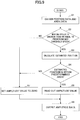
- FIG. 9 is a flowchart illustrating the process that is executed by the drive controlling part 240 of the drive controlling apparatus 300 of the electronic device 100 according to the embodiment.
- An operating system (OS) of the electronic device 100 executes control for driving the electronic device 100 every predetermined control cycle. Accordingly, the drive controlling apparatus 300 performs calculation for every predetermined control cycle to repeatedly execute the flow illustrated in FIG. 9 . The same applies to the drive controlling part 240 , and the drive controlling part 240 repeatedly executes the flow illustrated in FIG. 9 for every predetermined control cycle.
- OS operating system
- a required duration of time from a point of time when position data is input from the driver IC 151 to the drive controlling apparatus 300 to a point of time when a driving signal is calculated by the drive controlling apparatus 300 based on the position data, is ⁇ t
- the required duration ⁇ t of time is substantially equal to the control cycle.
- a duration of time of one cycle of the control cycle can be treated as a duration of time corresponding to the required duration ⁇ t of time, which is required from the point of time at which the position data is input to the drive controlling apparatus 300 from the driver IC 151 to the point of time at which the driving signal is calculated based on the input position data.
- the drive controlling part 240 starts the process when the electronic device 100 is powered on.
- the drive controlling part 240 obtains area data, associated with a vibration pattern, in step S 1 in accordance with coordinates represented by the current position data and with a type of a current application.
- the area data is associated with a vibration pattern.
- the drive controlling part 240 determines whether the moving speed is greater than or equal to the predetermined threshold speed in step S 2 .
- the moving speed may be calculated by a vector operation.
- the threshold speed may be set as the minimum speed of the moving speed of the user's fingertip performing the manipulation input while moving the user's fingertip such as a flick operation, a swipe operation, a drag operation or the like. Such a minimum speed may be set based on an experimental result, a resolution of the touch panel 150 or the like.
- step S 2 the drive controlling part 240 calculates in step S 3 estimated coordinates of after the elapse of the duration ⁇ t of time based on the coordinates represented by the current position data and based on the moving speed.
- the drive controlling part 240 determines in step S 4 whether the estimated coordinates after the elapse of the duration ⁇ t of time are located within an area St which is represented by the area data obtained in step S 1 .
- the drive controlling part 240 determines that the estimated coordinates after the elapse of the duration ⁇ t of time are within the area St represented by the area data obtained in step S 1 , the drive controlling part 240 obtains in step S 5 , from the pattern data, amplitude data representing an amplitude value corresponding to the moving speed obtained in step S 2 .
- the drive controlling part 240 outputs the amplitude data in step S 6 .
- the amplitude modulator 320 generates a driving signal by modulating the amplitude of the sinusoidal wave output from the sinusoidal wave generator 310 , and the vibrating element 140 is driven by the driving signal.
- the drive controlling part 240 sets the amplitude value to be zero in step S 7 .
- the drive controlling part 240 outputs amplitude data of which the amplitude value is zero, and the amplitude modulator 320 generates a driving signal by modulating the amplitude of the sinusoidal wave output from the sinusoidal wave generator 310 to be zero. Accordingly, in this case, the vibrating element 140 is not driven.
- FIGS. 10 and 11 are diagrams illustrating an example of the operation of the electronic device 100 according to the embodiment.
- a XYZ coordinate system similar to that in FIG. 2 to FIG. 4 is defined.
- FIG. 10 is a diagram illustrating the top panel 120 , the touch panel 150 and the display panel 160 in plan view, where the user of the electronic device 100 touches a page 1 indicated in grey with his or her fingertip and is about to open a page 2 indicated in white by performing a swipe operation leftward. That is, the page displayed on the electronic device 100 is about to transition from the page 1 to the page 2 .
- the drive controlling part 240 determines whether the manipulation input is a swipe operation. For example, upon the user's fingertip moving by ⁇ d mm or more in the X axis direction from a starting position at which the user touches the top panel 120 first with the user's fingertip, the drive controlling part 240 determines that a swipe operation is being performed, and generates a vibration at the top panel 120 when the user's fingertip enters into areas indicated by oblique lines. The areas indicated by oblique lines are the area St.
- a vibration generated at the top panel 120 will be described with reference to FIG. 11 .
- the vibration is generated by a driving signal output from the amplitude modulator 320 based on amplitude data output from the drive controlling part 240 .
- the horizontal axis represents time
- the vertical axis represents the amplitude value of the amplitude data.
- the moving speed of the user's fingertip is approximately constant when the user performs the swipe operation.
- the user touches the top panel 120 at the position C 1 with his or her fingertip and begins to move his or her fingertip along the surface of the top panel 120 leftward at the time point t 1 .
- the drive controlling part 240 determines that the manipulation input of the user is a swipe operation and performs driving with the vibration pattern for the swipe operation.
- An operating distance d mm which is used for determining the swipe operation, corresponds to a length of the move of the user's fingertip during a period of time between the time point t 1 and the time point t 2 .
- the page transition is started.
- the amplitude of the vibration pattern for the swipe operation is A 11 , and is a driving pattern in which the vibration continues while the swipe operation is being performed.
- the drive controlling part 240 sets the amplitude value to be zero. Accordingly, the amplitude is set to be zero immediately after the time point t 3 . Further, at the time point t 4 after the time point t 3 , the page transition is completed.
- the drive controlling part 240 outputs the amplitude data having a constant amplitude value (A 11 ), for example. Therefore, the kinetic friction force applied to the user's fingertip is reduced while the user is performing the swipe operation. As a result, it is possible to provide the slippery or smooth touch (texture) to the user. Accordingly, the user can recognize that the swipe operation is being accepted by the electronic device 100 through the user's fingertip.
- the intensity of the natural vibration may be changed.
- the intensity of the natural vibration may be changed in accordance with an amount of the manipulation of the slider 102 B or when reaching a scale mark of the slider 102 .
- the position of the vibrating element 140 at the top panel 120 and a displacement and a curvature of the top panel 120 will be described.
- the end parts of the top panel 120 are assumed to be free ends.
- FIG. 12 and FIG. 13 are diagrams illustrating the position of the vibrating element 140 at the top panel 120 and a displacement and a curvature of the top panel 120 .
- the level of the displacement and the curvature are exaggerated such that the displacement and the curvature of the top panel 120 are easily understood.
- the points where the displacement is 0 indicate nodes of the natural vibration
- the points where the displacement is the maximum indicate antinodes of the natural vibration.
- the curvature is a physical quantity obtained by differentiating the displacement twice.
- the displacement is represented by a sinusoidal wave (a sine wave)
- the curvature is at the opposite phase because of being represented by ⁇ sin.
- the displacement and the curvature are illustrated in the same phase.
- the vibrating element 140 is disposed at the position of the second antinode from the positive side end part of the top panel 120 in the Y axis direction (position between the second node and the third node from the end part).
- the width of the vibrating element 140 in the Y axis direction is half (0.5 ⁇ ) of the wavelength ⁇ of a sinusoidal wave (a sine wave) representing the displacement of the top panel 120 .
- the wavelength ⁇ is a wavelength of a sinusoidal wave representing a displacement occurring at the top panel 120 , and is a value obtained without considering the vibrating element 140 .
- the width of the vibrating element 140 in the Y axis direction is set to be 0.5 ⁇ so as to locate the vibrating element 140 between the second node and the third node in the Y axis direction, from the positive side end part of the top panel 120 in the Y axis direction. This is because it is considered that vibration can efficiently be generated at the top panel 120 by locating the vibrating element 140 of 0.5 ⁇ between a node and a node as described above.
- both the shape and the curvature indicate values deviated from values given by a trigonometric function. Note that the shape represented by the distribution of the displacement in the Y axis direction illustrated in FIG. 12 is referred to as the shape of the displacement.
- the vibration of the top panel 120 is theoretically a bending vibration of a beam, and a general solution of a standing wave of the bending vibration of the beam is expressed by the following formula (3).
- the formula (3) is described in “Theory of Mechanical Vibrations, 2 nd Ed., Toshihiro Irie”, for example.
- L is the length of the top panel 120 and can be treated as the length of the beam.
- the range of Y is from 0 to L.
- the vibrating element 140 A is disposed at the positive side end part of the top panel 120 in the Y axis direction.
- the vibrating element 140 A is basically similar to the vibrating element 140 illustrated in FIG. 12 , the width of the vibrating element 140 A in the Y axis direction is different from that of that of the vibrating element 140 .
- the vibrating element 140 A is a vibrating element disposed at the positive side end part in the Y axis direction.
- the width of the vibrating element 140 A in the Y axis direction is 0.625 ⁇ .
- the width of the vibrating element 140 A in the Y axis direction is set to be 0.625 ⁇ so as to locate, in the Y axis direction, the vibrating element 140 A between the positive side end part of the top panel 120 in the Y axis direction and the second node, from the positive side end part of the top panel 120 in the Y axis direction. Because outward from the second node is considered to be in a state specific to the end, the width of the vibrating element 140 A in the Y axis direction is set to be 0.625 ⁇ .
- the distance from the end to the second node is approximately 0.625 ⁇ .
- the curvature is 0 at the panel end and at the second node from the panel end, and the curvature is of the same sign between them. It is considered that vibration can be efficiently generated at the top panel 120 by locating the vibrating element 140 , whose width is 0.625 ⁇ , between the positive side end part of the top panel 120 in the Y axis direction and the second node, from the positive side end part of the top panel 120 in the Y axis direction.
- FIG. 14 and FIG. 15 are diagrams that describe a state in which the top panel 120 and the vibrating element 140 bend.
- the vibrating element 140 Upon the vibrating element 140 extending from a state in which the top panel 120 and the vibrating element 140 are not bent as illustrated in FIG. 14 , to a state as illustrated in FIG. 15 , a difference between the length of the top panel 120 and the length of the vibrating element 140 generates a bending force. Thereby, a vibration occurs at the top panel. Conversely, upon the vibrating element 120 contracting, a bending force occurs towards the opposite side. In order to generate bending and generate a standing wave by deforming the vibrating element as described above, the vibrating element 140 is required to be attached to a portion where the curvature of the standing wave is not zero.
- FIG. 16 is a diagram illustrating a state in which the top panel 120 and the vibrating element 140 are bent.
- the flexural rigidity of the sections P to which the vibrating element 140 is not attached differs from the flexural rigidity of the section C to which the vibrating element 140 is attached. That is, the flexural rigidity of the top panel 120 and the vibrating element 140 at the section C, where the top panel 120 and the vibrating element 140 are superimposed and fixed, is different from the flexural rigidity of the top panel 120 at the sections P of the top panel 120 alone.
- the sections where the vibrating element 140 is not attached are sections of the top panel 120 only and are sections where the top panel 120 is present alone.
- the flexural rigidity of the top panel 120 and the vibrating element 140 at the section C, where the top panel 120 and the vibrating element 140 are superimposed and fixed is referred to as Mc
- the flexural rigidity of the top panel 120 at the sections P of the top panel 120 alone is referred to as Mp.
- the flexural rigidity Mc is larger than the flexural rigidity Mp. Note that for the sections P of the top panel 120 alone, only sections adjacent to the section C are illustrated.
- the width of the vibrating element 140 in the Y axis direction is the width of the vibrating element 140 in a direction in which the displacement of the natural vibration in the ultrasound frequency band varies.
- the width of the vibrating element 140 in the Y axis direction is described.
- the width of the vibrating element 140 in the Y axis direction is referred to as W.
- the wavelength of a sinusoidal wave representing the displacement occurring at the top panel 120 is referred to as ⁇ c. This is different from the above described wavelength ⁇ .
- the above described wavelength ⁇ is the wavelength of a sinusoidal wave representing the displacement occurring at the top panel 120 and is a value obtained without considering the vibrating element 140 .
- FIG. 17 is a diagram illustrating a relationship between an optimum element width W/ ⁇ c and the rigidity ratio ⁇ .
- W/ ⁇ c is the ratio of the width W of the vibrating element 140 in the Y axis direction to the wavelength ⁇ c.
- the property indicated by the solid line indicates a property of the optimum element width W/ ⁇ c with respect to the rigidity ratio ⁇ in a case where the vibrating element 140 is disposed, as illustrated in FIG. 12 , at a position of the second antinode from the positive side end part of the top panel 120 in the Y axis direction.
- the property indicated by the broken line indicates a property of the optimum element width W/ ⁇ c with respect to the rigidity ratio ⁇ in a case where the vibrating element 140 A is disposed, as illustrated in FIG. 13 , at the positive side end part of the top panel 120 in the Y axis direction.
- the rigidity ratio ⁇ is set to be 0 when the flexural rigidity Mc is extremely larger than the flexural rigidity Mp and, W/ ⁇ c is set to be 0.75 when the rigidity ratio ⁇ is 0.
- the width W of the vibrating element 140 in the Y axis direction is 0.5 ⁇ .
- the case where the rigidity ratio ⁇ is 1 is considered to match the case of considering the top panel alone in the arrangement of FIG. 13 .
- the optimum width of the vibrating element 140 A in the Y axis direction is 0.625 ⁇ .
- W/ ⁇ c is set to be 0.625.
- the property of the formula (5) is applied under conditions the same as those in the case of the antinode in FIG. 12 .
- the vibration shape at other antinodes is approximately in a trigonometric function, and is equal to that of the case illustrated in FIG.
- the vibrating element 140 is arranged at the position of the second antinode from the positive side end part of the top panel 120 in the Y axis direction. Therefore, to a case where the end part of the top panel 120 is a fixed end, the property of the formula (5) is applied. In a case where the end is a rotatable supported end of the displacement 0, the vibration shape is in a trigonometric function, and the property of the formula (5) is applied to all antinodes including the endmost antinode.
- the case in which the rigidity ratio ⁇ is 0 is a case in which the flexural rigidity Mp is very small with respect to the flexural rigidity Mc.
- the rigidity ratio ⁇ is 0, even when the top panel 120 is vibrated in a mode of the natural vibration of the entire top panel 120 , the displacement of the section where the vibrating element 140 is overlapped with and attached to the top panel 120 is considered to be equal to a vibration in a case where both ends of the section where the vibrating element 140 is overlapped with and attached to the top panel 120 are free ends. This is because the flexural rigidity Mp of the top panel 120 alone is extremely smaller than the flexural rigidity Mc.
- FIG. 18 is a diagram illustrating a primary resonance mode of a beam having free ends at both ends.
- the beam having free ends at both ends is a model of the section where the vibrating element 140 is overlapped with and attached to the top panel 120 .
- the width of the beam is indicated by the horizontal direction.
- the upper part of FIG. 18 indicates the displacement of the model of the section where the top panel 120 is overlapped with and attached to the vibrating element 140 (the shape represented by the distribution of the displacement in the Y axis direction), and the lower part of FIG. 18 indicates the distribution of the curvature of the model.
- the curvature can be obtained by differentiating the displacement twice. Note that the displacement of the model (the shape represented by the distribution of the displacement in the Y axis direction) indicates the shape of the vibration in the Y axis direction.
- the width W of the vibrating element 140 in a case where the rigidity Mc of the section where the vibrating element 140 is overlapped with and attached to the top panel 120 is large, is fitted to the condition of primary resonance in a case where both ends of the section where the vibrating element 140 is overlapped with and attached to the top panel 120 are free ends.
- ⁇ c is determined depending on a frequency and the like of the natural vibration, and is similar in a case of a beam with one layer and a case of a beam with two layers
- the formula for the case of two layers is indicated by the following formula (7).
- the flexural rigidity Mc is a flexural rigidity of a beam with two layers
- ⁇ 1 and ⁇ 2 are respective densities of the two layers of the beam
- t 1 and t 2 are respective thicknesses of the two layers of the beam.
- ⁇ c (2 ⁇ / f ) 1/2 ⁇ Mc /( ⁇ 1 t 1 + ⁇ 2 t 2 ) ⁇ 1/4 (7)
- a target of a frequency of the natural vibration in the ultrasound frequency band to be generated at the top panel 120 is determined in advance, and a mode of the natural vibration obtained by a frequency close to the targeted frequency is used.
- the targeted frequency is determined.
- the vibrating element 140 is driven at the targeted frequency, how to set a value of the width W of the vibrating element 140 is discussed.
- the width W is 0.75 ⁇ c
- the shape of a vibration obtained at the section where the vibrating element 140 is overlapped with and attached to the top panel 120 (the shape represented by the distribution in the Y axis direction of the displacement) is regarded as the same as the shape of a vibration in primary resonance at free ends of the beam illustrated in FIG. 18 , from the boundary condition of free ends, the curvature at both ends of the section, where the vibrating element 140 is overlapped with and attached to the top panel 120 , is 0.
- the curvature is of the same sign.
- the sign of the curvature represents whether the curvature illustrated in the lower part of FIG. 18 is above (the positive side) or below (the negative side) 0 in the vertical axis direction.
- the curvature being of the same sign means the distribution of the curvature being either in the positive side or in the negative side with respect to the Y axis direction.
- the curvature is of the same sign between both ends of the section, where the vibrating element 140 is overlapped with and attached to the top panel 120 as illustrated in the upper part of FIG. 18 , it is suitable for bending the top panel 120 by expansion and contraction of the vibrating element 140 .
- the width W of the vibrating element 140 is larger than 0.75 ⁇ c, the shape of vibration extends outwardly as compared with a case where primary resonance illustrated in FIG. 18 occurs, and the extended portion becomes a shape in which the curvature is reversed. That is, because an effect of canceling the bending vibration is generated, the efficiency is decreased.
- E is the Young's modulus
- d is the length of the top panel 120 in the X axis direction
- t is the thickness of the top panel 120 .
- the top panel 120 has a unit length in the X axis direction.
- the flexural rigidity Mp is obtained from the following formula (11) as a moment per curvature (1/r).
- the center in the thickness direction is taken as the origin of Z, and the integration range is from ⁇ t/2 to t/2.
- the same flexural rigidity result as in the formula (8) is obtained.
- the value of the length d of the top panel 120 in the X axis direction is set to be 1 (unit length).
- FIG. 19 illustrates a section in which the vibrating element 140 is overlapped with and attached to the top panel 120 as a beam with two layers.
- the thickness of the first layer (the top panel 120 ) is referred to as “a” and the Young's modulus of the first layer is referred to as “Ea”.
- the thickness of the second layer (the vibrating element 140 ) is referred to as “b” and the Young's modulus of the second layer is referred to as “Eb”.
- the origin of Z is the position of the lower surface of the first layer (the top panel 120 ).
- the moment can be obtained by summing the contributions of the infinitesimal parts ⁇ Z for the first layer and the second layer.
- the flexural rigidity Mc of the beam with two layers can be obtained by the following formula (16) by using Z 0 of the formula (15).
- the flexural rigidity Mc of the section, where the vibrating element 140 is overlapped with and attached to the top panel 120 can be calculated from the Young's modulus, the thickness, and the like.
- the wavelength ⁇ c at the section, where the vibrating element 140 is overlapped with and attached to the top panel 120 can be obtained from the formula (7).
- the flexural rigidity Mc can be similarly obtained, and the present embodiment can be applied.
- FIG. 20 illustrates results in which, when the thickness t of the glass used as the top panel 120 is 0.3 mm, the vibrating elements 140 and 140 A are made of ceramic having a thickness of 0.3 mm, and the rigidity ratio ⁇ is 0.13, the width W is varied and analyzed by finite element analysis to plot values of amplitude of the natural vibration of the top panel 120 .
- FIG. 20 illustrates a graph for a case where the vibrating element 140 is arranged at the position of the second antinode from the positive side end part of the top panel 120 in the Y axis direction and for a case where the vibrating element 140 A is arranged at the positive side end part of the top panel 120 in the Y axis direction.
- the amplitude of the vibration generated at the top panel 120 is the maximum when W/ ⁇ c is approximately 0.75. Note that it is found that the wavelength ⁇ c of the section where the vibrating element 140 is overlapped with and attached to the top panel 120 is larger, by approximately 20%, than the wavelength ⁇ p of the top panel 120 alone.
- FIG. 20 indicates the results analyzed with the arrangement in which the center of the vibrating element 140 is fitted in the position of an antinode of the natural vibration of the top panel 120 alone, when the vibrating element 140 is attached to the top panel 120 .
- the simulation result shows that the amplitude of the natural vibration became large by setting the center of the vibrating element 140 in the position of an antinode of the natural vibration of the top panel 120 alone.
- the vibration shape of the section, where the vibrating element 140 is overlapped with and attached to the top panel 120 differs from that of the top panel 120 alone due to the effect of the rigidity of the vibrating element 140
- the position to which the vibrating element 140 is attached may be a position of an antinode calculated for the top panel 120 alone.
- FIG. 21 is a diagram illustrating an example of a vibration shape of the analyzed results.
- the vibration shape for when the top panel 120 to which the vibrating element 140 is attached is vibrated is indicated by the reference numerals 120 a and 140 a.
- the vibration shape in FIG. 21 of the section, where the vibrating element 140 is overlapped with and attached to the top panel 120 is near a vibration shape of a case obtained by taking only the section, where the vibrating element 140 is overlapped with and attached to the top panel 120 , as being one with free ends.
- the ratio (rigidity ratio) a between the flexural rigidity Mp of the top panel 120 alone and the flexural rigidity Mc of the section, where the vibrating element 140 is overlapped with and attached to the top panel 120 is 1, and the flexural rigidity Mp is equal to the flexural rigidity Mc. That is, the rigidity of the beam with two layers is not varied by the vibrating element 140 , and the vibration is the same as the natural vibration of the top panel 120 alone considered in FIG. 12 and FIG. 13 .
- the wavelength ⁇ c in the section, where the vibrating element 140 is overlapped with and attached to the top panel 120 is the same as the wavelength ⁇ p in the case of the top panel 120 alone. Further, when the vibrating element 140 is arranged at the position of the second antinode from the positive side end part of the top panel 120 in the Y axis direction, the optimum value of the width W of the vibrating element 140 is 0.5 ⁇ c, and when the vibrating element 140 is arranged at the end of the top panel 120 , the optimum value of the width W of the vibrating element 140 is 0.625 ⁇ c.
- the optimum width W of the vibrating element 140 can be estimated.
- the optimum width is estimated to change, as illustrated in FIG. 17 , linearly with respect to the rigidity ratio ⁇ as indicated by the formula (5) and the formula (6).
- the validity of the above estimation is verified by using results of finite element analysis with respect to four types of values of rigidity ratios ⁇ .
- the results of the case 1 are as illustrated in FIG. 20 . Further, the case 3 will be described with reference to FIG. 22 and FIG. 23 . Further, the case 2 will be described with reference to FIG. 24 .
- FIG. 22 is a diagram illustrating amplitude of the natural vibration with respect to the width W in the case 3 in which the vibrating element 140 is arranged at the position of the second antinode from the positive side end part of the top panel 120 in the Y axis direction.
- FIG. 23 is a diagram illustrating an analysis result where the vibrating element 140 A is arranged at the end part of the top panel 120 .
- FIG. 24 is a diagram illustrating, for the case 2, amplitude of the natural vibration with respect to the width W for when the vibrating element 140 is arranged at the position of the second antinode from the positive side end part of the top panel 120 in the Y axis direction and for when the vibrating element 140 A is arranged at the end part of the top panel 120 .
- the amplitude is the maximum when the width W is 0.63 ⁇ c. Further, in FIG. 23 , the amplitude is the maximum when the width W is 0.71 ⁇ c.
- the amplitude is the maximum when the width W is 0.65 ⁇ c.
- the amplitude is the maximum when the width W is 0.70 ⁇ c.
- FIG. 25 is a diagram illustrating, for the cases 1 to 4, results of plotting, with respect to the flexural rigidity ratio ⁇ , the width W at which the maximum amplitude is obtained.
- straight lines corresponding to the formulas (5) and (6) are also displayed.
- the results illustrated in FIG. 25 indicate that the width W that gives the maximum amplitude obtained by the finite element analysis substantially matches the width W of the formula (5) and the formula (6), and indicate that the estimation that the optimum width W changes linearly with respect to the flexural rigidity a is valid.
- the ratio (rigidity ratio) a between the flexural rigidity Mp of the top panel 120 alone and the flexural rigidity Mc of the section, where the vibrating element 140 is overlapped with and attached to the top panel 120 can be calculated.
- the wavelength ⁇ c of the section, where the vibrating element 140 is overlapped with and attached to the top panel 120 can be calculated.
- the amplitude of the natural vibration can be increased by setting the width W such that a large amplitude is obtained as illustrated in FIG. 20 and FIG. 22 .
- an amplitude greater than or equal to this amplitude can be obtained, for example, in the range of 0.5 ⁇ c ⁇ W ⁇ 0.88 ⁇ c in FIG. 20 .
- the reason why the amplitude obtained when the width W is 0.5 ⁇ c is used as a reference is that, in ignoring the effect of the vibrating element on the rigidity and the like, the optimum value of the width W of the vibrating element 140 is 0.5 ⁇ c when the vibrating element 140 is arranged at the position of the second antinode from the positive side end part of the top panel 120 in the Y axis direction.
- W (0.85 ⁇ 0.35 ⁇ ) ⁇ c (17)
- the amplitude of the natural vibration can be increased by setting the width W such that a large amplitude is obtained as illustrated in FIG. 20 and FIG. 23 .
- an amplitude greater than or equal to this amplitude can be obtained, for example, in the range of 0.5 ⁇ c ⁇ W ⁇ 0.81 ⁇ c in FIG. 23 .
- the reason why the amplitude obtained when the width W is 0.625 ⁇ c is used as a reference is that, in ignoring the effect of the vibrating element on the rigidity and the like, the optimum value of the width W of the vibrating element 140 is 0.625 ⁇ c when the vibrating element 140 is arranged at the positive side end part of the top panel 120 in the Y axis direction.
- W (0.81 ⁇ 0.185 ⁇ ) ⁇ c (19)
- a configuration in which the rigidity ratio ⁇ is close to 1 does not appreciably differ, in a width W considered as optimum in the present embodiment, from the configuration illustrated in FIG. 12 in which the width of the vibrating element 140 in the Y axis direction is set to be 0.5 ⁇ and the configuration illustrated in FIG. 13 in which the width of the vibrating element 140 A in the Y axis direction is set to be 0.625 ⁇ , and its amplitude increase effect is slight.
- the present embodiment is effective when being applied to a configuration where the rigidity ratio ⁇ is small, in particular, a configuration where the rigidity ratio ⁇ is less than or equal to 0.35.
- a configuration in which the thickness of the top panel 120 is reduced or a configuration in which the thickness of the vibrating element 140 is increased may be adopted. Both of the configurations are considered not to be disadvantageous for generating a vibration at the top panel 120 and but to work advantageously.
- the electronic device 100 in which the rigidity ratio ⁇ is reduced and the width W is set to be in the range expressed by the formula (19) or the formula (20) can provide a favorable tactile sensation.
- an amplitude of the top panel 120 obtained by setting the width W to be in the range expressed by the formula (18) becomes an amplitude equal to or higher than an amplitude obtained when the width W is 0.5 ⁇ c, but does not necessarily become equal to or higher than an amplitude obtained when the vibrating element 140 whose width W is greater than or equal to 0.625 ⁇ c is installed at the positive side end part of the top panel 120 in the Y axis direction.
- an amplitude in a case where the vibrating element 140 is arranged at the position of the second antinode from the positive side end part of the top panel 120 in the Y axis direction is smaller than an amplitude in a case where the vibrating element 140 is arranged at the positive side end part of the top panel 120 in the Y axis direction.
- the vibrating element 140 when the top panel 120 is fixed to the housing 110 , there may be a case where the vibrating element 140 cannot be arranged at the positive side end part of the top panel 120 in the Y axis direction. In such a case, the vibrating element 140 is arranged at the position of the second antinode from the positive side end part of the top panel 120 in the Y axis direction.
- the end part of the top panel 120 is a fixed end.
- the end part of the top panel 120 differs, in conditions, from the end part of the top panel in FIG. 13 , and the formula (20) cannot be applied.
- the vibrating element 140 by arranging the vibrating element 140 at an antinode of the vibration of the top panel 120 and by setting a width W obtained in the formula (18), an amplitude sufficient for a favorable vibration can be obtained similarly to the case in which the vibrating element 140 is arranged at the position of the second antinode from the positive side end part of a free end top panel 120 in the Y axis direction.
- the electronic device 100 of the embodiment generates the driving signal by causing the amplitude modulator 320 to modulate only the amplitude of the sinusoidal wave, which is in the ultrasound frequency band, generated by the sinusoidal wave generator 310 .
- the frequency of the sinusoidal wave in the ultrasound frequency band generated by the sinusoidal wave generator 310 is equal to the natural vibration frequency of the top panel 120 . Further, this natural vibration frequency is set in consideration of the vibrating element 140 .
- the driving signal is generated by the amplitude modulator 320 modulating only the amplitude of the sinusoidal wave in the ultrasound frequency band generated by the sinusoidal wave generator 310 , without modulating the frequency or the phase of the sinusoidal wave.
- the top panel 120 it is possible to generate, at the top panel 120 , the natural vibration in the ultrasound frequency band of the top panel 120 and to decrease with certainty the kinetic friction coefficient applied to the user's finger tracing the surface of the top panel 120 by utilizing the layer of air provided by the squeeze effect. Further, it is possible to provide a favorable tactile sensation to the user as if a concavo-convex portion were present on the surface of the top panel 120 by utilizing the Sticky-band Illusion effect or the Fishbone Tactile Illusion effect.
- the vibrating element 140 in order to provide a tactile sensation to the user as if a concave-convex portion were present on the top panel 120 , the vibrating element 140 is switched on/off. Turning off the vibrating element 140 is equal to setting the amplitude value, represented by the driving signal used to drive the vibrating element 140 , to be zero.
- the vibrating element 140 may be driven to decrease the amplitude instead of turning off the vibrating element 140 .
- a tactile sensation may be provided to the user as if a concave-convex portion were present on the top panel 120 by decreasing the amplitude to approximately one-fifth.
- the vibrating element 140 is driven by the driving signal such that the intensity of the vibration of the vibrating element 140 is changed.
- the intensity of the natural vibration generated at the top panel 120 is changed, and it is possible to provide the tactile sensation to the user's fingertip as if a concavo-convex portion were present.
- FIG. 28 is a diagram illustrating a cross section of an electronic device 100 C according to a variation example of the embodiment.
- the cross section illustrated in FIG. 28 corresponds to a cross section taken along the line A-A as illustrated in FIG. 3 .
- an XYZ coordinate system which is an orthogonal coordinate system, similar to that illustrated in FIG. 3 is defined.
- the electronic device 100 C includes a housing 110 B, the top panel 120 , a panel 121 , the double-faced adhesive tape 130 , the vibrating element 140 , the touch panel 150 , a display panel 160 A, and the substrate 170 .
- the electronic device 100 C has a configuration in which the touch panel 150 of the electronic device 100 illustrated in FIG. 3 is provided on the back face side (the negative side in the Z axis direction).
- the double-faced adhesive tape 130 , the vibrating element 140 , the touch panel 150 , and the substrate 170 are disposed on the back face side.
- a recessed portion 110 A at the positive side in the Z axis direction and a recessed portion 110 C at the negative side in the Z axis direction are formed on the housing 110 B.
- the display panel 160 A is disposed inside the recessed portion 110 A and is covered with the top panel 120 .
- the substrate 170 and the touch panel 150 are stacked and disposed inside the recessed portion 110 C.
- the panel 121 is secured to the housing 110 B with the double-faced adhesive tape 130 .
- the vibrating element 140 is disposed on a positive side surface of the top panel 121 in the Z axis direction.
- FIG. 28 illustrates the electronic device 100 C in which the touch panel 150 is provided at the back surface side
- the touch panel 150 may be provided for each of the front surface side and the back surface side by combining the structure illustrated in FIG. 3 and the structure illustrated in FIG. 28 .
- FIG. 29 is a diagram illustrating an electronic device 100 D of a variation example of the embodiment.
- the electronic device 100 D is a notebook Personal Computer (PC).
- the PC 100 D includes a display panel 160 B 1 and a touch pad 160 B 2 .
- FIG. 30 is a diagram illustrating a cross section of the touch pad 160 B 2 of the electronic device 100 D of the variation example of the embodiment.
- the cross section illustrated in FIG. corresponds to a cross section taken along the line A-A as illustrated in FIG. 3 .
- an XYZ coordinate system which is an orthogonal coordinate system, similar to that illustrated in FIG. 3 is defined.
- the touch pad 160 B 2 has a configuration in which the display panel 160 is omitted from the electronic device 100 illustrated in FIG. 3 .
- an operational feeling can be provided to the user's fingertip through tactile sensations in accordance with an amount of movement of the manipulation input performed on the touch pad 160 B 2 .
- the vibrating element 140 at the back surface of the display panel 160 B 1 , in a way similar to that of the electronic device 100 illustrated in FIG. 3 , an operational feeling can be provided to the user's fingertip through tactile sensations in accordance with an amount of movement of the manipulation input performed on the display panel 160 B 1 .
- the electronic device 100 illustrated in FIG. 3 may be provided instead of the display panel 160 B 1 .
- FIG. 31 is a diagram illustrating a cross section of an electronic device 100 E of a variation example of the embodiment.
- the electronic device 100 E includes the housing 110 , a top panel 120 C, the double-faced adhesive tape 130 , the vibrating element 140 , the touch panel 150 , the display panel 160 and the substrate 170 .
- the electronic device 100 E illustrated in FIG. 31 has a configuration similar to that of the electronic device 100 of the embodiment illustrated in FIG. 3 .
- the top panel 120 C is curved such that its center portion in plan view protrudes towards a positive side in the Z axis direction.
- FIG. illustrates a cross sectional shape of the top panel 120 C in the YZ plane
- a cross sectional shape in a XZ plane is similar to the cross sectional shape in the YZ plane.
Abstract
Description
W=(0.75−0.25×α)×λc (5)
W=(0.75−0.125×α)×λc (6)
λc=(2π/f)1/2 {Mc/(ρ1 t 1+ρ2 t 2)}1/4 (7)
M p =EI=Edt 3/12 (8)
W=(0.85−0.35α)λc (17)
0.5λc≤W≤(0.85−0.35α)λc (18)
W=(0.81−0.185α)λc (19)
0.625λc≤W≤(0.81−0.185α)λc (20)
Claims (3)
Applications Claiming Priority (1)
| Application Number | Priority Date | Filing Date | Title |
|---|---|---|---|
| PCT/JP2015/084469 WO2017098592A1 (en) | 2015-12-09 | 2015-12-09 | Electronic device |
Related Parent Applications (1)
| Application Number | Title | Priority Date | Filing Date |
|---|---|---|---|
| PCT/JP2015/084469 Continuation WO2017098592A1 (en) | 2015-12-09 | 2015-12-09 | Electronic device |
Publications (2)
| Publication Number | Publication Date |
|---|---|
| US20180275786A1 US20180275786A1 (en) | 2018-09-27 |
| US10592019B2 true US10592019B2 (en) | 2020-03-17 |
Family
ID=59013785
Family Applications (1)
| Application Number | Title | Priority Date | Filing Date |
|---|---|---|---|
| US15/993,467 Expired - Fee Related US10592019B2 (en) | 2015-12-09 | 2018-05-30 | Electronic device |
Country Status (5)
| Country | Link |
|---|---|
| US (1) | US10592019B2 (en) |
| EP (1) | EP3388924B1 (en) |
| JP (1) | JP6566045B2 (en) |
| CN (1) | CN108292177B (en) |
| WO (1) | WO2017098592A1 (en) |
Cited By (1)
| Publication number | Priority date | Publication date | Assignee | Title |
|---|---|---|---|---|
| US20220179509A1 (en) * | 2019-04-26 | 2022-06-09 | Hap2U | Haptic feedback device provided with stiffeners |
Families Citing this family (5)
| Publication number | Priority date | Publication date | Assignee | Title |
|---|---|---|---|---|
| US10739906B2 (en) * | 2018-01-10 | 2020-08-11 | Denso Ten Limited | Operation input device and touch panel |
| CN112534380A (en) * | 2018-08-29 | 2021-03-19 | 阿尔卑斯阿尔派株式会社 | Input device, control method, and program |
| JP7370190B2 (en) * | 2019-08-14 | 2023-10-27 | 太陽誘電株式会社 | Panels and electronic equipment |
| CN112329331B (en) * | 2020-10-15 | 2022-04-29 | 湖北工业大学 | Natural frequency and vibration mode configuration method based on mixed addition of mass and rigidity |
| CN115357124B (en) * | 2022-09-20 | 2023-09-05 | 武汉市聚芯微电子有限责任公司 | Vibration control method, device, equipment and storage medium |
Citations (6)
| Publication number | Priority date | Publication date | Assignee | Title |
|---|---|---|---|---|
| US20090085439A1 (en) * | 2007-09-28 | 2009-04-02 | Denso Corporation | Ultrasonic sensor |
| WO2010104019A1 (en) | 2009-03-12 | 2010-09-16 | Ricoh Company, Ltd. | Touch panel device, display device equipped with touch panel device, and control method of touch panel device |
| JP2013097438A (en) | 2011-10-28 | 2013-05-20 | Mitsubishi Electric Corp | Tactile sense presentation device |
| JP2013228885A (en) | 2012-04-25 | 2013-11-07 | Kyocera Corp | Panel device |
| US20140347322A1 (en) | 2013-09-26 | 2014-11-27 | Fujitsu Limited | Drive controlling apparatus, electronic device and drive controlling method |
| WO2015005103A1 (en) | 2013-07-11 | 2015-01-15 | 太陽誘電株式会社 | Vibration device and electronic device using same |
Family Cites Families (5)
| Publication number | Priority date | Publication date | Assignee | Title |
|---|---|---|---|---|
| JP4224677B2 (en) * | 2002-09-13 | 2009-02-18 | 富士電機システムズ株式会社 | Optical encoder position detection method |
| WO2006075764A1 (en) * | 2005-01-13 | 2006-07-20 | Nec Corporation | Oscillatory gyroscope |
| KR20080048837A (en) * | 2006-11-29 | 2008-06-03 | 삼성전자주식회사 | Apparatus and method for outputting tactile feedback on display device |
| CN104395866B (en) * | 2012-11-30 | 2018-02-23 | 松下知识产权经营株式会社 | Tactile cue device and tactile cue method |
| JP5849061B2 (en) * | 2013-03-28 | 2016-01-27 | 京セラドキュメントソリューションズ株式会社 | Display input device and image forming apparatus having the same |
-
2015
- 2015-12-09 JP JP2017554706A patent/JP6566045B2/en active Active
- 2015-12-09 EP EP15910208.6A patent/EP3388924B1/en active Active
- 2015-12-09 CN CN201580085082.7A patent/CN108292177B/en active Active
- 2015-12-09 WO PCT/JP2015/084469 patent/WO2017098592A1/en unknown
-
2018
- 2018-05-30 US US15/993,467 patent/US10592019B2/en not_active Expired - Fee Related
Patent Citations (10)
| Publication number | Priority date | Publication date | Assignee | Title |
|---|---|---|---|---|
| US20090085439A1 (en) * | 2007-09-28 | 2009-04-02 | Denso Corporation | Ultrasonic sensor |
| WO2010104019A1 (en) | 2009-03-12 | 2010-09-16 | Ricoh Company, Ltd. | Touch panel device, display device equipped with touch panel device, and control method of touch panel device |
| JP2010238222A (en) | 2009-03-12 | 2010-10-21 | Ricoh Co Ltd | Touch panel device, touch panel-equipped display device including the same and control method for the touch panel device |
| US20110291976A1 (en) | 2009-03-12 | 2011-12-01 | Ricoh Company, Ltd | Touch panel device, display device equipped with touch panel device, and control method of touch panel device |
| JP2013097438A (en) | 2011-10-28 | 2013-05-20 | Mitsubishi Electric Corp | Tactile sense presentation device |
| JP2013228885A (en) | 2012-04-25 | 2013-11-07 | Kyocera Corp | Panel device |
| WO2015005103A1 (en) | 2013-07-11 | 2015-01-15 | 太陽誘電株式会社 | Vibration device and electronic device using same |
| US20160170539A1 (en) | 2013-07-11 | 2016-06-16 | Taiyo Yuden Co., Ltd. | Vibrating device and electronic device using same |
| US20140347322A1 (en) | 2013-09-26 | 2014-11-27 | Fujitsu Limited | Drive controlling apparatus, electronic device and drive controlling method |
| JP5780368B1 (en) | 2013-09-26 | 2015-09-16 | 富士通株式会社 | Drive control apparatus, electronic device, and drive control method |
Non-Patent Citations (8)
| Title |
|---|
| Extended European search report dated Nov. 16, 2018 issued with respect to the corresponding European patent application No. 15910208.6. |
| International Search Report of Int. Appl. No. PCT/JP2015/084469 dated Feb. 16, 2016. |
| Masashi Nakatani et al., "The Fishbone Tactile Illusion", Collection of papers of the 10th Congress of the Virtual Reality Society of Japan, Sep. 2005. |
| Michael Wiertlewski et al., "Power Optimization of Ultrasonic Friction-Modulation Tactile Interfaces", IEEE Transactions on Haptics, vol. 8, No. 1, Jan.-Mar. 2015, pp. 43-53. |
| Takeyuki Dohda et al., "The Printed-matter Typecasting Method for Haptic Feel Design and Sticky-band Illusion", The collection of papers of the 11th SICE system integration division annual conference (SI2010, Sendai), Dec. 2010, pp. 174 to 177 Abstract. |
| Toshihiro Irie, "Theory of Mechanical Vibrations, 2nd Edition", pp. 122-127 translation of the relevant part. |
| Toshihiro Irie, "Theory of Mechanical Vibrations, 2nd Edition", pp. 122-127, published Apr. 10, 1981 translation of the relevant part. |
| Written Opinion of Int. Appl. No. PCT/JP2015/084469 dated Feb. 16, 2016. |
Cited By (2)
| Publication number | Priority date | Publication date | Assignee | Title |
|---|---|---|---|---|
| US20220179509A1 (en) * | 2019-04-26 | 2022-06-09 | Hap2U | Haptic feedback device provided with stiffeners |
| US11875000B2 (en) * | 2019-04-26 | 2024-01-16 | Hap2U | Haptic feedback device provided with stiffeners |
Also Published As
| Publication number | Publication date |
|---|---|
| WO2017098592A1 (en) | 2017-06-15 |
| EP3388924B1 (en) | 2022-01-05 |
| EP3388924A1 (en) | 2018-10-17 |
| JPWO2017098592A1 (en) | 2018-09-20 |
| JP6566045B2 (en) | 2019-08-28 |
| CN108292177B (en) | 2021-01-26 |
| CN108292177A (en) | 2018-07-17 |
| US20180275786A1 (en) | 2018-09-27 |
| EP3388924A4 (en) | 2018-12-19 |
Similar Documents
| Publication | Publication Date | Title |
|---|---|---|
| US10592019B2 (en) | Electronic device | |
| US10216338B2 (en) | Electronic device | |
| US9400571B2 (en) | Drive controlling apparatus, electronic device and drive controlling method | |
| US10031585B2 (en) | Electronic device, drive controlling method, and drive controlling apparatus | |
| US10042423B2 (en) | Electronic device and drive control method | |
| US20160349847A1 (en) | Electronic device, input apparatus, and drive controlling method | |
| US20180018022A1 (en) | Electronic device, coordinate detecting unit, and adhesive member | |
| US20180024638A1 (en) | Drive controlling apparatus, electronic device, computer-readable recording medium, and drive controlling method | |
| US11086435B2 (en) | Drive control device, electronic device, and drive control method | |
| US10359850B2 (en) | Apparatus and method for switching vibration at panel surface | |
| US11003250B2 (en) | Electronic device | |
| US11119609B2 (en) | Electronic device | |
| US11068101B2 (en) | Electronic device including vibrating element for generating vibration in operation surface of top panel | |
| AU2015202408B2 (en) | Drive controlling apparatus, electronic device and drive controlling method |
Legal Events
| Date | Code | Title | Description |
|---|---|---|---|
| FEPP | Fee payment procedure |
Free format text: ENTITY STATUS SET TO UNDISCOUNTED (ORIGINAL EVENT CODE: BIG.); ENTITY STATUS OF PATENT OWNER: LARGE ENTITY |
|
| AS | Assignment |
Owner name: FUJITSU LIMITED, JAPAN Free format text: ASSIGNMENT OF ASSIGNORS INTEREST;ASSIGNORS:MIYAMOTO, AKINORI;KAMATA, YUICHI;TANINAKA, KIYOSHI;AND OTHERS;SIGNING DATES FROM 20180427 TO 20180508;REEL/FRAME:045955/0091 |
|
| STPP | Information on status: patent application and granting procedure in general |
Free format text: DOCKETED NEW CASE - READY FOR EXAMINATION |
|
| STPP | Information on status: patent application and granting procedure in general |
Free format text: NON FINAL ACTION MAILED |
|
| STPP | Information on status: patent application and granting procedure in general |
Free format text: RESPONSE TO NON-FINAL OFFICE ACTION ENTERED AND FORWARDED TO EXAMINER |
|
| STPP | Information on status: patent application and granting procedure in general |
Free format text: NOTICE OF ALLOWANCE MAILED -- APPLICATION RECEIVED IN OFFICE OF PUBLICATIONS |
|
| STPP | Information on status: patent application and granting procedure in general |
Free format text: PUBLICATIONS -- ISSUE FEE PAYMENT VERIFIED |
|
| STCF | Information on status: patent grant |
Free format text: PATENTED CASE |
|
| FEPP | Fee payment procedure |
Free format text: MAINTENANCE FEE REMINDER MAILED (ORIGINAL EVENT CODE: REM.); ENTITY STATUS OF PATENT OWNER: LARGE ENTITY |
|
| LAPS | Lapse for failure to pay maintenance fees |
Free format text: PATENT EXPIRED FOR FAILURE TO PAY MAINTENANCE FEES (ORIGINAL EVENT CODE: EXP.); ENTITY STATUS OF PATENT OWNER: LARGE ENTITY |