US1058982A - Loom for weaving reticulate reinforcements. - Google Patents
Loom for weaving reticulate reinforcements. Download PDFInfo
- Publication number
- US1058982A US1058982A US66623411A US1911666234A US1058982A US 1058982 A US1058982 A US 1058982A US 66623411 A US66623411 A US 66623411A US 1911666234 A US1911666234 A US 1911666234A US 1058982 A US1058982 A US 1058982A
- Authority
- US
- United States
- Prior art keywords
- loom
- disks
- warp
- shaft
- reticulate
- Prior art date
- Legal status (The legal status is an assumption and is not a legal conclusion. Google has not performed a legal analysis and makes no representation as to the accuracy of the status listed.)
- Expired - Lifetime
Links
Images


Classifications
-
- D—TEXTILES; PAPER
- D03—WEAVING
- D03D—WOVEN FABRICS; METHODS OF WEAVING; LOOMS
- D03D29/00—Hand looms
Definitions
- WITNESSES INVENTOR- ROBERT M. JONES, OF DENVER, COLORADO.
- My invention relates to looms for weay'ing l reticulate reinforcementsfor use in concrete structures and its object resides in the provision of a mechanism of simple construction by which metallic bars and wires may be woven into a reticulate article of either flat, cylindrical, or conoidal form. I attain.
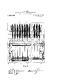
- Figure 1 represents an elevation of the loom with the warps and filling of which the woven product is produced, in the operative position
- Fig. 2 a fragmentary frontelevation of the same looking in the direction of the arrow A
- weaving-machine consists of a suitable base X upon which are erected an upright frame X for the support of the loom-harness and a the mechanism b which the same is operated, ;standards V for the support of a horizontal-shaft Y upon which the warp-reels A arefmounted, and standards which support the element of the mechanism by which the'relative position of the parts constituting the filling or weft of the woven product is determined and by which said product is shaped to the desired form.
- the reels A are loosely mounted upon the shaft Y to more independently about the axis-thereof while the machine is in operation, they are spaced from each other to permit of a limited lateral displacement and they are each provided with an integral sheave-member T of reduced diamcter, to receive a rope or cable S one end of whlch is securely fastened upon the base X while weights U are suspended from their opposite ends after they have been placed over the respective sheaves, for the purpose of holding the warp tautand keeping the proper strain thereof while it is being paid off the reels.
- the shaft Y has a longitudinal key way Specification of Letters Patent.
- the loom harness consists of the twoheda dle frames C each provided with a "plurality. of heddles E and respectively? attached at opposite sides of a pair of'endless ropes or cables I looped around two drums D which are mounted to rotate about horizontal axes in suitable bearings secured near the upper and lower ends of the upright frame X.
- the drums D are connect ed to rotate in unison, by means of endless] chains R which are placed around sprocket j "wheels Q secured upon the opposite ends of"? the shafts :D" of the respective drums and the upper one of these shafts carries in addition, a hand wheel H by means of which the two drums are rotated to alternate'the position of the heddle frames in the operation of the machine.
- toothed wheels K are mounted upon the-shaft of the upper one adjacent the sprocket whee'ls and a series of double gravity pawls L of'difi'erent lengths are pivotally connected upon blocks secured to the frame X to engage the toothed peripheries of the wheels K at either side of the perpendicular passing through their center.
- the element by which the rods comprised in the weft or filling of the woven product, are spaced and by which the said product may be formed into either a cylinder or a conoid, consists of a shaft B which is rotatably supported in bearings on the before mentioned standards W and upon which a series of disks J are fixedly mounted, The disks which, collectively, provide a drum or reel. upon which the woven product is wound, as will hereinafter be explained, are provided with equidistant peripheral notches which are placed in 'alinement for the receptioh of the rods F which constitute the web of the reticulate reinforcement.- When the machine is employed to wear: 1
- the disks are how "erotated b means of the lever inthe di- 5Jection .o the arrow d through renal-c substantially equal to the distance'between two' smx'zessivenotches in their' peripherles'after.
- the lever brings a third. series of notches within" reach, of the operator who 'agam draws a rod 'F through the wet it iii-the said notches after' which e re verses the position oft ep'awlsL andturns
- the shaft. B is intermittently rotated by means of,levers and laces strands are twisted together with the ends of the wires projecting beyondthe first rod to complete.
- e continuity of thmreticulate reinforcement which in accordancewith the relative sizes of thedisks is either cylindrical or conoidal in form.
- the combination with means for the decussation of the strands comprised in the warp of a plurality of disks mounted to rotate in unison about a common axis and having series of peripheral notches in alinement with each other for the support of rods which constitute the Weft of the product of the loom, the said disks being-spaced from each other for the passage of the warp strands between them at right angles to their axis of rotation, a rod supported in one of the series of alined notches to which the ends of the warp strands are secured, and means for imparting an intermittent rotary movement to the said disks.
Landscapes
- Engineering & Computer Science (AREA)
- Textile Engineering (AREA)
- Woven Fabrics (AREA)
Description
R. M. JONES.
.LOOM FOR WEAVING RETIGULATE RBINFORCEMENTS.
' .APPLIUATION FILED DEO.16, 1911.
1,058,982, v f Patented 15, 1913.
3 $HEETS-SHEET 1.
FIE-:1. I v WITNESSES INVENTOR- R. M. JONES.
LOOM FOR WEA'VING RETIGULATE REINFORGEMENTS.
.APPLIOATION TILED 13130.16, 1911. 1&5 9% I mam 2913 3 SHEETfi-SEEET 2.
I W [I WITNESSES: INVENTOR.
R. M. JONES.
LOOM FOR WBAVING RETIOULATE EEINPORGEMENTS.
APPLICATION FILED D110. 16, 1911.
1,058,982. I a Patented Apr. 15, 1913.
3 SHEETS-SHEET 3.
FIG-3.
WITNESSES: INVENTOR- ROBERT M. JONES, OF DENVER, COLORADO.
LOOM FOR WEAVING RETICULATE REINFORCEMENTS.
To all whom 2'1 may concern Be it known that I, ROBERT M. JONES,"I
citizen of the United States, residing at Denver. in the county of Denver and State 5 of Colorado, have invented certain new and useful Improvements in Looms for \Veaving Reticulate Reinforcen'ients, of which the following is a specification.
My invention relates to looms for weay'ing l reticulate reinforcementsfor use in concrete structures and its object resides in the provision of a mechanism of simple construction by which metallic bars and wires may be woven into a reticulate article of either flat, cylindrical, or conoidal form. I attain.
this object by the mechanism shown'in the accompanying drawings in the various views of which like parts are similarly designated and in which, v
Figure 1 represents an elevation of the loom with the warps and filling of which the woven product is produced, in the operative position, Fig. 2 a fragmentary frontelevation of the same looking in the direction of the arrow A, Fig. 1, and Fig. 3 a
fragmentary plan view of the machine.
Referring to the drawings by letters, the
weaving-machine consists of a suitable base X upon which are erected an upright frame X for the support of the loom-harness and a the mechanism b which the same is operated, ;standards V for the support of a horizontal-shaft Y upon which the warp-reels A arefmounted, and standards which support the element of the mechanism by which the'relative position of the parts constituting the filling or weft of the woven product is determined and by which said product is shaped to the desired form.
The reels A are loosely mounted upon the shaft Y to more independently about the axis-thereof while the machine is in operation, they are spaced from each other to permit of a limited lateral displacement and they are each provided with an integral sheave-member T of reduced diamcter, to receive a rope or cable S one end of whlch is securely fastened upon the base X while weights U are suspended from their opposite ends after they have been placed over the respective sheaves, for the purpose of holding the warp tautand keeping the proper strain thereof while it is being paid off the reels.
The shaft Y has a longitudinal key way Specification of Letters Patent.
Application filed December 16, 1911.
Serial No. 666,234.
Y extending from one of itsends the Patented Apr. 15, .1913.
other and the reels are each provided witha corresponding key-seat A, so that by insertion of a key into. the way Y and the seat A of one 'of the reels, the latter may be, fixed on the shaft when it is desired to wind the warp upon the reel at thed'nitial point of the operation, which may be readily accomplished by rotating the shaft in its bearings .by any suitable means such as the' crank Y shown in Fig. 3 of the drawings.
The loom harness consists of the twoheda dle frames C each provided with a "plurality. of heddles E and respectively? attached at opposite sides of a pair of'endless ropes or cables I looped around two drums D which are mounted to rotate about horizontal axes in suitable bearings secured near the upper and lower ends of the upright frame X. The drums D are connect ed to rotate in unison, by means of endless] chains R which are placed around sprocket j "wheels Q secured upon the opposite ends of"? the shafts :D" of the respective drums and the upper one of these shafts carries in addition, a hand wheel H by means of which the two drums are rotated to alternate'the position of the heddle frames in the operation of the machine.
To prevent retrograde movement of the two drums, toothed wheels K are mounted upon the-shaft of the upper one adjacent the sprocket whee'ls and a series of double gravity pawls L of'difi'erent lengths are pivotally connected upon blocks secured to the frame X to engage the toothed peripheries of the wheels K at either side of the perpendicular passing through their center.
The element by which the rods comprised in the weft or filling of the woven product, are spaced and by which the said product may be formed into either a cylinder or a conoid, consists of a shaft B which is rotatably supported in bearings on the before mentioned standards W and upon which a series of disks J are fixedly mounted, The disks which, collectively, provide a drum or reel. upon which the woven product is wound, as will hereinafter be explained, are provided with equidistant peripheral notches which are placed in 'alinement for the receptioh of the rods F which constitute the web of the reticulate reinforcement.- When the machine is employed to wear: 1
reinforcements of cylindrical form the several disks comprised 'in the series, are of equal diameters, while when the loom 1s operated to produce a conoidal reinforcement, the disks are progressivelyxreduced in 'di- 5 ameter from the outer one at one end of the shaft B, to the opposite one at the other extremity of the same. The last describedarrangement of disks drawings.
I P which are rumed u'pon'the ends there- 'of and which carry series of overbalanced pawls N of diiferent lengths which respec-' tively engage the toothed peripheries of two ratchet-wheels M, fixedly mounted upon the shaft. Gravity dogs 0 pivoted onthe standards W are place in engagement with the teeth of the respective w eels M to prevent retrograde movement of the rotatory element and stops X adjustably' secured upon the u right frame X are providedto determine f t e extent of the movement-of the-levers P and,'in consequence that of the are through The warp of'the reticulate rein orcement prodiice'd by. the operation of the machine, consist'slof double wires which in the drawings are indicated by single lines G, and
so which are wound u on the reels A, and the web or fillingof a reinforcement is provlded by rods F which in the 'o' eration are placed in .thealinedperiphera notches 'of the dished... I To wind 'thedouble which consti i tute the warp, upon the-reels A, the latter are oneafter, -other,lfi'xed onthe shaft Y;
i y fTk8insertedin the corresponding key-seats and -'A',"and the shaft. V as rotated inqtlie direction of the arrow-O,
, Fig. 'Lby'meansofthe crank When as many reels ha'vebeen'supplied-with wire,'as
I ai-erequired to. reduce a reinforcement of a determinateh the iriction cables S-which 5 had been removed from" the shteaves T durj mg-the operation of -windin'gthewarp onthe reels, are-replaced in, e position shown in- 4 chineas shown 'anddescribed is particularly a the drawings,'and the-two wires wound-zen each reel are sin y drawn through the eyes 6 of opposite hed eson the two frames-G and their ends are secured by twisting, to a rod F which has been placed in alineii notches of the disks'on'the shaft B. The disks are how "erotated b means of the lever inthe di- 5Jection .o the arrow d through renal-c substantially equal to the distance'between two' smx'zessivenotches in their' peripherles'after.
- which afsecondrod is placed" inthis web e5 curing the rod- F- in place, by a partial rota;
has I -"en shownin thel.
which the shaft. B is intermittentl rotated.
the lever brings a third. series of notches within" reach, of the operator who 'agam draws a rod 'F through the wet it iii-the said notches after' which e re verses the position oft ep'awlsL andturns In the operation of the loom, the shaft. B is intermittently rotated by means of,levers and laces strands are twisted together with the ends of the wires projecting beyondthe first rod to complete. e continuity of thmreticulate reinforcement," which in accordancewith the relative sizes of thedisks is either cylindrical or conoidal in form.
To produce a flat reinforcement, it is only necessary to withdraw the rods comprised m en ,the warp 1s,
the filling, from the notches in the disks after the latter have been partially rotated and it will be understood that by varying the perimetrical form of th disks the machine may be efiectively employed to produce reinforcements of quadrangular form. I c
'As the reels A rotateindependentl'y-on the shaftY, and are constantl restrained by. the geln'ent of the weighted cables 8 with the s eaves I, the saidreelswill, in
the operation-of the machine, rotate'm mittently at velocities" differing in ratio fr 'the diameters of the oppositely disposed disks J and the-spaced relation of-the reels, as shown-in ,Fig. 3, makes it powble tolaterally dis lace the same, when it is desired to insert t e ,keys'in the correspondingjkeyw ys Y and A, for the purpose of'windthe warp.
1'. will be that while the ma;
adapted for the productionfof reticulate rein orcements fol-concrete sta'uctures, it may, if 0' desired,'be'efi'ectivelyemgio ed in the manufact of fencing and t e Ike.
Having tghidescribed myinvention what "I claim and desire to secure'by Letters-Patentis,
1. In a loom of the class described, the
combination with means for the decussation of the strands comprised in the war of a plurality of disks mounted to rotate 1n unison about a common axis and having series (if peri heral notches in: alinement with each bther' or the support of rods which constitute the weft of the 'prodhct'of the loom, the said,disks being s aced from each other for the .passage 0 .t e warp strands between them at right an les to their axis of rotation, andmeans or imparting an intermittent rotary movement to said -disks.
I 2. In a loom of the class described, thecombination with'means for the decussation of the strands comprised in the warp, of a plurality of disks of progressively increasing diameters mounted to rotate in unison about a common axis and having series of peripheral notches in alinementwith each other for the support of rods which constitute the weft of the product of the 100m,- the said disks beings aced from each other for the passage of the warp strands between them at right angles to their axis of rotation, and means for imparting an intermit tent rotary movement to said disks.-
3. Ina loom of the class'described, the combination with means for the decussation of the strands comprised in the warp, of a plurality of disks mounted to rotate in unison about a common axis and having series of peripheral notches in alinement with each other for the support of rods which constitute the Weft of the product of the loom, the said disks being-spaced from each other for the passage of the warp strands between them at right angles to their axis of rotation, a rod supported in one of the series of alined notches to which the ends of the warp strands are secured, and means for imparting an intermittent rotary movement to the said disks.
4. Ina 100m of the class described, the combination with means for, the decussation of the strands comprised in the warp, of a plurality of disks mounted to rotate in unison about a common axis and having series of peripheral notches in alinement with each'otherfor the support of rods Which constitute the weft of the product of. the loom, the said disks being spaced from each other for thepassage of t e warp strands be- ,tween them at right-angles to their axis of rotation, means for imparting an intermittent rotary movement to said disks, and ad justable means to determine and vary the extent of said movement.
In testimony whereof I have afiixed my signature in presence of two witnesses. ROBERT M. JONES.
Witnesses:
A. B. Jonas, KmBY V. JONES.
Copies of this patent may be obtained for five cents each, by addressing the Commissioner of Patents,
Washington, I). G. i
Priority Applications (1)
| Application Number | Priority Date | Filing Date | Title |
|---|---|---|---|
| US66623411A US1058982A (en) | 1911-12-16 | 1911-12-16 | Loom for weaving reticulate reinforcements. |
Applications Claiming Priority (1)
| Application Number | Priority Date | Filing Date | Title |
|---|---|---|---|
| US66623411A US1058982A (en) | 1911-12-16 | 1911-12-16 | Loom for weaving reticulate reinforcements. |
Publications (1)
| Publication Number | Publication Date |
|---|---|
| US1058982A true US1058982A (en) | 1913-04-15 |
Family
ID=3127235
Family Applications (1)
| Application Number | Title | Priority Date | Filing Date |
|---|---|---|---|
| US66623411A Expired - Lifetime US1058982A (en) | 1911-12-16 | 1911-12-16 | Loom for weaving reticulate reinforcements. |
Country Status (1)
| Country | Link |
|---|---|
| US (1) | US1058982A (en) |
Cited By (1)
| Publication number | Priority date | Publication date | Assignee | Title |
|---|---|---|---|---|
| US2480064A (en) * | 1946-08-05 | 1949-08-23 | Walker Gordon | Revetment fabricating machine |
-
1911
- 1911-12-16 US US66623411A patent/US1058982A/en not_active Expired - Lifetime
Cited By (1)
| Publication number | Priority date | Publication date | Assignee | Title |
|---|---|---|---|---|
| US2480064A (en) * | 1946-08-05 | 1949-08-23 | Walker Gordon | Revetment fabricating machine |
Similar Documents
| Publication | Publication Date | Title |
|---|---|---|
| US787183A (en) | Bundling apparatus. | |
| US57226A (en) | Improvement in hand-looms | |
| US307448A (en) | drown | |
| US372197A (en) | Machine for weaving fences | |
| US606760A (en) | Wire-stretcher | |
| US260551A (en) | Wire-stretcher | |
| US194741A (en) | Improvement in circular looms | |
| US560734A (en) | Slat-and-wire-fence machine | |
| US1056120A (en) | Wire-stretcher. | |
| US450573A (en) | Harry haynes | |
| US243012A (en) | Machinery for weaving cane | |
| US194740A (en) | Improvement in circular looms | |
| US397814A (en) | Fence-machine | |
| US939308A (en) | Rope-making machine. | |
| US471571A (en) | Tension device | |
| US780637A (en) | Woven-wire stretcher. | |
| US334113A (en) | Pieeee dtjeangolsr | |
| US472167A (en) | Hand fence-machine | |
| US342524A (en) | g-ilbert | |
| US4608A (en) | Netting-machine | |
| US809096A (en) | Wire-stretcher. | |
| US69159A (en) | peters | |
| US644011A (en) | Wire-fence machine. | |
| US568791A (en) | Stay-wire-winding machine | |
| US189353A (en) | Improvement in circular looms |