US10589727B1 - Adjustable motor mount for semi-trailer landing gear - Google Patents
Adjustable motor mount for semi-trailer landing gear Download PDFInfo
- Publication number
- US10589727B1 US10589727B1 US15/346,628 US201615346628A US10589727B1 US 10589727 B1 US10589727 B1 US 10589727B1 US 201615346628 A US201615346628 A US 201615346628A US 10589727 B1 US10589727 B1 US 10589727B1
- Authority
- US
- United States
- Prior art keywords
- plate
- landing gear
- semi
- adjustable motor
- trailer
- Prior art date
- Legal status (The legal status is an assumption and is not a legal conclusion. Google has not performed a legal analysis and makes no representation as to the accuracy of the status listed.)
- Expired - Fee Related, expires
Links
- 238000000034 method Methods 0.000 description 4
- 238000009434 installation Methods 0.000 description 3
- 230000009977 dual effect Effects 0.000 description 2
- 229910000831 Steel Inorganic materials 0.000 description 1
- 230000006378 damage Effects 0.000 description 1
- 239000002184 metal Substances 0.000 description 1
- 238000012986 modification Methods 0.000 description 1
- 230000004048 modification Effects 0.000 description 1
- 230000001105 regulatory effect Effects 0.000 description 1
- 239000010959 steel Substances 0.000 description 1
Images


Classifications
-
- B—PERFORMING OPERATIONS; TRANSPORTING
- B60—VEHICLES IN GENERAL
- B60S—SERVICING, CLEANING, REPAIRING, SUPPORTING, LIFTING, OR MANOEUVRING OF VEHICLES, NOT OTHERWISE PROVIDED FOR
- B60S9/00—Ground-engaging vehicle fittings for supporting, lifting, or manoeuvring the vehicle, wholly or in part, e.g. built-in jacks
- B60S9/22—Means for attaching lifting, supporting, or manoeuvring devices to vehicles
-
- B—PERFORMING OPERATIONS; TRANSPORTING
- B60—VEHICLES IN GENERAL
- B60S—SERVICING, CLEANING, REPAIRING, SUPPORTING, LIFTING, OR MANOEUVRING OF VEHICLES, NOT OTHERWISE PROVIDED FOR
- B60S9/00—Ground-engaging vehicle fittings for supporting, lifting, or manoeuvring the vehicle, wholly or in part, e.g. built-in jacks
- B60S9/02—Ground-engaging vehicle fittings for supporting, lifting, or manoeuvring the vehicle, wholly or in part, e.g. built-in jacks for only lifting or supporting
- B60S9/04—Ground-engaging vehicle fittings for supporting, lifting, or manoeuvring the vehicle, wholly or in part, e.g. built-in jacks for only lifting or supporting mechanically
- B60S9/06—Ground-engaging vehicle fittings for supporting, lifting, or manoeuvring the vehicle, wholly or in part, e.g. built-in jacks for only lifting or supporting mechanically of screw-and-nut type
- B60S9/08—Ground-engaging vehicle fittings for supporting, lifting, or manoeuvring the vehicle, wholly or in part, e.g. built-in jacks for only lifting or supporting mechanically of screw-and-nut type the screw axis being substantially vertical
Definitions
- This invention relates to adjustable motor mounts and, particularly, to an adjustable motor mount for attaching a motor to the crank shaft of the landing gear of a semi-trailer.
- Many semi-trailers have a front landing gear for support of the front of the trailer when the tractor is detached.
- Such landing gears generally have two spaced-apart, telescoping or Jack-type landing gear legs and feet which extend downwardly from the floor of the trailer.
- Each leg is operatively attached to screw and follower or a rack and pinion gear arrangement which is driven by a landing gear drive shaft which extends between the legs and which causes extension or retraction of the legs and feet depending on the direction in which it is rotated.
- a hand operable handle or crank is attached to the landing gear drive shaft by a pin or bolt which serves as a hinge connection allowing the handle to be pivoted out of the way while not in use.
- Manual rotation of the handle in one direction causes extension of the feet and lifting of the trailer to, for example, separate the trailer from a semi-tractor, and requires considerable time and effort on the part of the person manually rotating the hand crank.
- Manually operated jack structures are often difficult to use, require much time for their operation and expose the operator to potential injuries as he is positioned next to the trailer while turning the crank to raise or lower the landing gear to in turn raise or lower the trailer.
- a number of devices for mechanically or electrically extending and retracting the landing gear of a semi-trailer are known. These devices are, in general, cumbersome and expensive and generally require installation of such devices on the semi-trailer at the time of installation of the landing gear thereon. Owing primarily to the complexity and expense of the prior art systems, they have not enjoyed widespread acceptance in the trucking industry. Also, the complexity of such systems has rendered them relatively fragile and therefore generally unsuited to the rugged environment to which over-the-road semi-trailers are subjected daily.
- the present invention is an adjustable motor mount having a first plate with a first side, a second opposite side, a second plate, and a third plate.
- a first is hinge positioned between the first plate and the second plate.
- a second hinge is positioned between the second plate and the third plate.
- the second plate is rotatable relative to the first plate and the third plate is rotatable relative to the second plate.
- the third plate can be raised or lowered relative to the first plate and the third plate can be moved towards or away from the first plate.
- the first plate and the second plate having spaced hinge members so that the second plate and the third plate are slidable towards the first side and the second side of the first plate.
- the first plate is mountable to the frame of a semi-trailer and the third plate is mountable to a motor.
- the adjustable motor mount is useful for aligning a drive shaft of a motor to the crank shaft of a landing gear drive mechanism of a semi-trailer.
- a motor is attached to the third plate and the first plate is attached to the frame of a semi-trailer.
- the shaft of the motor is aligned with the crank shaft of the landing gear drive mechanism by moving the third plate towards or away from the first plate.
- the shaft of the motor is further aligned with the crank shaft of the landing gear drive mechanism by moving the third plate upwards or downwards relative to the first plate.
- the shaft of motor is attached to the crank shaft of the landing gear drive mechanism by moving the third plate towards the shaft of the landing gear drive mechanism.
- the shaft of the motor is removed from the drive shaft of the landing gear drive mechanism by moving the third plate away from the crank shaft of the landing gear drive mechanism.
- An advantage of the adjustable motor mount of the present invention is a motor mount that allows the motor to be easily moved upward, downward, left, right, towards, and away from the crank shaft of the landing gear drive mechanism.
- Another advantage is an adjustable motor mount that is easy to install on the frame of a semi-trailer.
- Another advantage is an adjustable motor mount that can fit any landing gear drive mechanism.
- Another advantage is an adjustable motor mount that is rugged and durable.
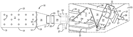
- FIG. 1 illustrates a top plan view of the adjustable motor mount of the present invention.
- FIG. 2 illustrates a bottom perspective view of the adjustable motor mount.
- FIG. 3 shows a top perspective view of the adjustable motor mount attached to the frame of a semi-trailer, with a motor attached to the motor mount and with a drive shaft of the motor aligned with and attached to the drive shaft of a landing gear drive mechanism.
- FIG. 1 shows a top plan view of the adjustable motor mount 10 of the present invention.
- the motor mount has a first plate 11 having a first end 12 , a second opposite end 13 , a first side 14 , and a second opposite side 15 .
- the first plate 11 is designed for mounting to the frame of a semi-trailer, for example, to the floor joists.
- a second plate 16 has a first end 17 and a second opposite end 18 .
- a hinge 19 connects the second plate 16 rotatably to the first plate 11 .
- a third plate 20 has a first end 21 and a second opposite end 22 .
- a hinge 23 connects the third plate 20 rotatably to the second plate 16 .
- a motor 24 is shown attached to the third plate 20 near the first end 21 of the third plate 20 .
- the motor 24 can be attached to the third plate 20 by any suitable method, for example, with a U-bolt 25 .
- a drive shaft 26 of the motor 24 can have a connecting coupler 27 to reversibly connect the drive shaft 26 to the crank shaft 28 of a landing gear drive mechanism with a clip pin 37 . (see FIG. 3 ).
- FIG. 2 shows a bottom perspective view of the adjustable motor mount 10 .
- FIG. 2 further shows that the first plate 11 and the second plate 16 have an alternate embodiment of the hinge 19 of FIG. 1 .
- both plates 11 and 16 have hinge members 29 with spaces 30 therebetween.
- the hinge members 29 on the second plate 16 can slide along a hinge pin 38 in the spaces 30 .
- second plate 16 can be moved to slide towards the first side 14 or towards the second opposite side 15 of the first plate 11 , resulting in the movement of the third plate 20 towards the first side 14 or towards the second opposite side 15 of the first plate 11 .
- the third plate 20 can be moved above or below the plane of the first plate 11 , toward or away from the first plate 11 , and towards the first side 14 or the second opposite side 15 of the first plate 11 .
- Holes 31 can be put in the first plate 11 for mounting the first plate 11 to the frame of a semi-trailer.
- Holes 32 can be put in the third plate 20 to attach the motor 24 to the third plate 20 .
- FIG. 3 shows the adjustable motor mount 10 placed under a semi-trailer 33 .
- the first plate 11 is attached to floor joists 34 of the semi-trailer 33 .
- a landing gear crankshaft 28 is shown extending under the semi-trailer 33 through an opening 35 .
- the first plate 11 extends towards a landing gear drive shaft 36 .
- the second plate 16 extends down below the landing gear drive shaft 36 and the third plate 20 extends upward.
- a motor 24 is attached to the third plate 20 .
- the motor 24 can be moved up, down, left, right, towards, or away from the landing gear crankshaft 28 by means of the dual hinge mechanism of the adjustable motor mount 10 .
- the connecting coupler 27 on the drive shaft 26 of the motor 24 can, thus, be easily aligned with the landing gear crankshaft 28 .
- the connecting coupler 27 can then be placed over the landing gear crankshaft 28 and reversibly locked into place with the clip pin 37 .
- the plates can be made of any suitable metal, preferably steel. Any type of suitable motor can be used with the adjustable motor mount, preferably an electric motor.
- the motor can be powered and regulated to turn both clockwise and counter clockwise by methods well known in the art to raise and lower the landing gear.
- the motor can also be operated remotely by methods well known in the art.
Landscapes
- Engineering & Computer Science (AREA)
- Mechanical Engineering (AREA)
- Vehicle Cleaning, Maintenance, Repair, Refitting, And Outriggers (AREA)
Abstract
An adjustable motor mount having a first plate with a first side and a second opposite side, a second plate, and a third plate. The first plate is connected to the second plate with a first hinge and the second plate is connected to the third plate with a second hinge. The second plate is rotatable relative to the first plate and the third plate is rotatable relative to the second plate. The third plate can be raised or lowered relative to the first plate and can be moved towards or away from the first plate. The first plate and the second plate may have spaced hinge members, as an alternate embodiment so that the second plate is slidable towards the first side and the second side of the first plate. The adjustable motor mount allows a motor to be easily moved upward, downward, left, right, towards, and away from a crank shaft of a landing gear drive mechanism.
Description
This application claims priority of U.S. Provisional Application Ser. No. 62/285,765 filed on Nov. 9, 2015, the disclosure of which is incorporated herein by reference.
This invention relates to adjustable motor mounts and, particularly, to an adjustable motor mount for attaching a motor to the crank shaft of the landing gear of a semi-trailer.
Many semi-trailers have a front landing gear for support of the front of the trailer when the tractor is detached. Such landing gears generally have two spaced-apart, telescoping or Jack-type landing gear legs and feet which extend downwardly from the floor of the trailer. Each leg is operatively attached to screw and follower or a rack and pinion gear arrangement which is driven by a landing gear drive shaft which extends between the legs and which causes extension or retraction of the legs and feet depending on the direction in which it is rotated.
Traditionally, a hand operable handle or crank is attached to the landing gear drive shaft by a pin or bolt which serves as a hinge connection allowing the handle to be pivoted out of the way while not in use. Manual rotation of the handle in one direction causes extension of the feet and lifting of the trailer to, for example, separate the trailer from a semi-tractor, and requires considerable time and effort on the part of the person manually rotating the hand crank. Manually operated jack structures, however, are often difficult to use, require much time for their operation and expose the operator to potential injuries as he is positioned next to the trailer while turning the crank to raise or lower the landing gear to in turn raise or lower the trailer.
A number of devices for mechanically or electrically extending and retracting the landing gear of a semi-trailer are known. These devices are, in general, cumbersome and expensive and generally require installation of such devices on the semi-trailer at the time of installation of the landing gear thereon. Owing primarily to the complexity and expense of the prior art systems, they have not enjoyed widespread acceptance in the trucking industry. Also, the complexity of such systems has rendered them relatively fragile and therefore generally unsuited to the rugged environment to which over-the-road semi-trailers are subjected daily.
What is needed is a simple, adjustable motor mount system for easy installation beneath the floor of a semi-trailer which will allow rapid and easy alignment and attachment of the drive shaft of the motor to the crank shaft of the landing gear of the semi-trailer.
The present invention is an adjustable motor mount having a first plate with a first side, a second opposite side, a second plate, and a third plate. A first is hinge positioned between the first plate and the second plate. A second hinge is positioned between the second plate and the third plate. The second plate is rotatable relative to the first plate and the third plate is rotatable relative to the second plate. The third plate can be raised or lowered relative to the first plate and the third plate can be moved towards or away from the first plate. The first plate and the second plate having spaced hinge members so that the second plate and the third plate are slidable towards the first side and the second side of the first plate. The first plate is mountable to the frame of a semi-trailer and the third plate is mountable to a motor.
The adjustable motor mount is useful for aligning a drive shaft of a motor to the crank shaft of a landing gear drive mechanism of a semi-trailer. A motor is attached to the third plate and the first plate is attached to the frame of a semi-trailer. The shaft of the motor is aligned with the crank shaft of the landing gear drive mechanism by moving the third plate towards or away from the first plate. The shaft of the motor is further aligned with the crank shaft of the landing gear drive mechanism by moving the third plate upwards or downwards relative to the first plate. The shaft of motor is attached to the crank shaft of the landing gear drive mechanism by moving the third plate towards the shaft of the landing gear drive mechanism. The shaft of the motor is removed from the drive shaft of the landing gear drive mechanism by moving the third plate away from the crank shaft of the landing gear drive mechanism.
An advantage of the adjustable motor mount of the present invention is a motor mount that allows the motor to be easily moved upward, downward, left, right, towards, and away from the crank shaft of the landing gear drive mechanism.
Another advantage is an adjustable motor mount that is easy to install on the frame of a semi-trailer.
Another advantage is an adjustable motor mount that can fit any landing gear drive mechanism.
Another advantage is an adjustable motor mount that is rugged and durable.
While the following description details the preferred embodiments of the present invention, it is to be understood that the invention is not limited in its application to the details of the method described herein, since the invention is capable of other embodiments and of being practiced in various ways.
The plates can be made of any suitable metal, preferably steel. Any type of suitable motor can be used with the adjustable motor mount, preferably an electric motor. The motor can be powered and regulated to turn both clockwise and counter clockwise by methods well known in the art to raise and lower the landing gear. The motor can also be operated remotely by methods well known in the art.
The foregoing description has been limited to specific embodiments of this invention. It will be apparent, however, that variations and modifications may be made, by those skilled in the art, to the disclosed embodiments of the invention, with the attainment of some or all of its advantages and without departing from the spirit and scope of the present invention.
Claims (12)
1. An adjustable motor mounting system comprising:
i) an adjustable motor mount comprising:
a) a first plate having a first side and a second side opposite said first side, said first plate having a first end and a second end opposite the first end of said first plate, a second plate having a first end and a second end opposite the first end of said second plate, and a third plate having a first end and a second end opposite the first end of said third plate;
b) a first hinge connecting the second end of said second plate to the first end of said first plate so that said second plate is rotatable relative to said first plate;
c) a second hinge connecting the first end of said second plate to the second end of said third plate so that said third plate is rotatable relative to said second plate, wherein said third plate is configured to be raised or lowered relative to said first plate and said third plate is configured to be moved towards or away from said first plate; and
d) the second end of said first plate attached to a frame of a semi-trailer, said second plate extending below a landing gear drive shaft of said semi-trailer, and said third plate extending upwards with respect to said landing gear drive shaft from said second plate; and
ii) a motor directly attached to a surface of said third plate at the first end of said third plate, wherein the first end of said third plate remains unhinged and wherein said motor is connected to a landing gear crank shaft of said semi-trailer.
2. The adjustable motor mounting system of claim 1 , wherein said first hinge comprises spaced hinge members on said first plate and on said second plate with a hinge pin therethrough so that said second plate is slidable on said hinge pin towards said first side of said first plate and towards said second side of said first plate.
3. The adjustable motor mounting system of claim 1 , wherein said motor is directly attached to said third plate at the first end of said third plate by a U-bolt.
4. The adjustable motor mounting system of claim 1 , further comprising a connecting coupler disposed on a drive shaft of said motor.
5. The adjustable motor mounting system of claim 4 , further comprising a clip pin configured to connect said connecting coupler to said landing gear crank shaft.
6. The adjustable motor mounting system of claim 1 , wherein said first plate comprises a plurality of holes for mounting said first plate to said frame of said semi-trailer.
7. The adjustable motor mounting system of claim 1 , wherein said third plate comprises a plurality of holes for attaching said motor to said third plate.
8. An adjustable motor mounting system comprising:
i) an adjustable motor mount comprising:
a) a first plate having a first side and a second side opposite said first side, said first plate having a first end and a second end opposite the first end of said first plate, a second plate having a first end and a second end opposite the first end of said second plate, and a third plate having a first end and a second end opposite the first end of said third plate;
b) a first hinge connecting the second end of said second plate to the first end of said first plate so that said second plate is rotatable relative to said first plate;
c) a second hinge connecting the first end of said second plate to the second end of said third plate so that said third plate is rotatable relative to said second plate, wherein said third plate is configured to be raised or lowered relative to said first plate and said third plate is configured to be moved towards or away from said first plate, and wherein said first hinge comprises spaced hinge members on said first plate and on said second plate with a hinge pin therethrough so that said second plate is slidable on said hinge pin towards said first side of said first plate and towards said second side of said first plate; and
d) the second end of said first plate attached to a frame of a semi-trailer, said second plate extending below a landing gear drive shaft of said semi-trailer, and said third plate extending upwards with respect to said landing gear drive shaft from said second plate; and
ii) a motor directly attached to a surface of said third plate at the first end of said third plate by a U-bolt, wherein the first end of said third plate remains unhinged and wherein said motor is connected to a landing gear crank shaft of said semi-trailer.
9. The adjustable motor mounting system of claim 8 , further comprising a connecting coupler disposed on a drive shaft of said motor.
10. The adjustable motor mounting system of claim 9 , further comprising a clip pin configured to connect said connecting coupler to said landing gear crank shaft.
11. The adjustable motor mounting system of claim 8 , wherein said first plate comprises a plurality of holes for mounting said first plate to said frame of said semi-trailer.
12. The adjustable motor mounting system of claim 8 , wherein said third plate comprises a plurality of holes for attaching said motor to said third plate.
Priority Applications (2)
| Application Number | Priority Date | Filing Date | Title |
|---|---|---|---|
| US15/346,628 US10589727B1 (en) | 2015-11-09 | 2016-11-08 | Adjustable motor mount for semi-trailer landing gear |
| US16/728,708 US10807571B1 (en) | 2015-11-09 | 2019-12-27 | Adjustable motor mount for semi-trailer landing gear |
Applications Claiming Priority (2)
| Application Number | Priority Date | Filing Date | Title |
|---|---|---|---|
| US201562285765P | 2015-11-09 | 2015-11-09 | |
| US15/346,628 US10589727B1 (en) | 2015-11-09 | 2016-11-08 | Adjustable motor mount for semi-trailer landing gear |
Related Child Applications (1)
| Application Number | Title | Priority Date | Filing Date |
|---|---|---|---|
| US16/728,708 Continuation-In-Part US10807571B1 (en) | 2015-11-09 | 2019-12-27 | Adjustable motor mount for semi-trailer landing gear |
Publications (1)
| Publication Number | Publication Date |
|---|---|
| US10589727B1 true US10589727B1 (en) | 2020-03-17 |
Family
ID=69779216
Family Applications (1)
| Application Number | Title | Priority Date | Filing Date |
|---|---|---|---|
| US15/346,628 Expired - Fee Related US10589727B1 (en) | 2015-11-09 | 2016-11-08 | Adjustable motor mount for semi-trailer landing gear |
Country Status (1)
| Country | Link |
|---|---|
| US (1) | US10589727B1 (en) |
Cited By (1)
| Publication number | Priority date | Publication date | Assignee | Title |
|---|---|---|---|---|
| US10807571B1 (en) * | 2015-11-09 | 2020-10-20 | Kelvin Lee Myrex | Adjustable motor mount for semi-trailer landing gear |
Citations (19)
| Publication number | Priority date | Publication date | Assignee | Title |
|---|---|---|---|---|
| US3895682A (en) * | 1973-09-26 | 1975-07-22 | Richard G Graham | Motor driven dolly actuator for semi-trailers and similar vehicles |
| US4281852A (en) * | 1977-09-15 | 1981-08-04 | Konkle Raymond L | Motion converting system |
| US4345779A (en) * | 1979-06-20 | 1982-08-24 | Busby Philip V | Drive mechanism for a vehicle trailer lifting gear |
| US5050845A (en) * | 1990-06-06 | 1991-09-24 | Aline Scott M | Pneumatic lift for trailers |
| US5058236A (en) * | 1990-02-06 | 1991-10-22 | Henson Ormel W | Adjustable hinge |
| US5933919A (en) * | 1997-06-02 | 1999-08-10 | Miller; Erik D. | Adjustable door hinge |
| US6086099A (en) * | 1998-05-08 | 2000-07-11 | Quest Transportation Products, Inc. | Trailer landing gear lifting apparatus |
| US6189458B1 (en) * | 1999-07-06 | 2001-02-20 | George Rivera | Collapsible table holder for attachment to a trailer hitch of a motor vehicle |
| US6945504B2 (en) * | 2002-08-20 | 2005-09-20 | King Slide Works Co., Ltd. | Adjustable cable management arm for furniture |
| US7328884B2 (en) * | 2005-11-22 | 2008-02-12 | Norco Industries, Inc. | Motor drive for a camper jack |
| US7469806B2 (en) * | 2005-09-28 | 2008-12-30 | Garoffolo Gregory L | Bicycle carrier apparatus for automobile |
| US7648112B2 (en) * | 2007-09-10 | 2010-01-19 | Andrew H. Lew | Flat panel display mounting device |
| US8235008B2 (en) * | 2006-11-28 | 2012-08-07 | T.F.H. Publications, Inc. | Foldable/collapsible structures |
| US8905872B2 (en) * | 2011-03-31 | 2014-12-09 | Nelson Ennis | Sporting goal transport system |
| US20150014506A1 (en) * | 2013-07-10 | 2015-01-15 | Thaddeus Brennan | Folding keyboard height extender |
| US8941978B2 (en) * | 2010-10-25 | 2015-01-27 | Jin Fang | Flat panel display remote-controlled viewing angle adjustment system |
| US9271884B2 (en) * | 2012-12-14 | 2016-03-01 | Design Par Mitchell Inc. | Personal storage accessory for wheelchairs |
| US9469280B2 (en) * | 2012-09-18 | 2016-10-18 | Razor International Pty Limited | Powered jacking leg |
| US9677307B2 (en) * | 2015-01-08 | 2017-06-13 | Michael T. McCuistion | Vertically floating hinge |
-
2016
- 2016-11-08 US US15/346,628 patent/US10589727B1/en not_active Expired - Fee Related
Patent Citations (20)
| Publication number | Priority date | Publication date | Assignee | Title |
|---|---|---|---|---|
| US3895682A (en) * | 1973-09-26 | 1975-07-22 | Richard G Graham | Motor driven dolly actuator for semi-trailers and similar vehicles |
| US4281852A (en) * | 1977-09-15 | 1981-08-04 | Konkle Raymond L | Motion converting system |
| US4345779A (en) * | 1979-06-20 | 1982-08-24 | Busby Philip V | Drive mechanism for a vehicle trailer lifting gear |
| US5058236A (en) * | 1990-02-06 | 1991-10-22 | Henson Ormel W | Adjustable hinge |
| US5050845A (en) * | 1990-06-06 | 1991-09-24 | Aline Scott M | Pneumatic lift for trailers |
| US5933919A (en) * | 1997-06-02 | 1999-08-10 | Miller; Erik D. | Adjustable door hinge |
| US6086099A (en) * | 1998-05-08 | 2000-07-11 | Quest Transportation Products, Inc. | Trailer landing gear lifting apparatus |
| US6189458B1 (en) * | 1999-07-06 | 2001-02-20 | George Rivera | Collapsible table holder for attachment to a trailer hitch of a motor vehicle |
| US6945504B2 (en) * | 2002-08-20 | 2005-09-20 | King Slide Works Co., Ltd. | Adjustable cable management arm for furniture |
| US7469806B2 (en) * | 2005-09-28 | 2008-12-30 | Garoffolo Gregory L | Bicycle carrier apparatus for automobile |
| US7328884B2 (en) * | 2005-11-22 | 2008-02-12 | Norco Industries, Inc. | Motor drive for a camper jack |
| US8052125B2 (en) * | 2005-11-22 | 2011-11-08 | Norco Industries, Inc. | Motor drive for a camper jack |
| US8235008B2 (en) * | 2006-11-28 | 2012-08-07 | T.F.H. Publications, Inc. | Foldable/collapsible structures |
| US7648112B2 (en) * | 2007-09-10 | 2010-01-19 | Andrew H. Lew | Flat panel display mounting device |
| US8941978B2 (en) * | 2010-10-25 | 2015-01-27 | Jin Fang | Flat panel display remote-controlled viewing angle adjustment system |
| US8905872B2 (en) * | 2011-03-31 | 2014-12-09 | Nelson Ennis | Sporting goal transport system |
| US9469280B2 (en) * | 2012-09-18 | 2016-10-18 | Razor International Pty Limited | Powered jacking leg |
| US9271884B2 (en) * | 2012-12-14 | 2016-03-01 | Design Par Mitchell Inc. | Personal storage accessory for wheelchairs |
| US20150014506A1 (en) * | 2013-07-10 | 2015-01-15 | Thaddeus Brennan | Folding keyboard height extender |
| US9677307B2 (en) * | 2015-01-08 | 2017-06-13 | Michael T. McCuistion | Vertically floating hinge |
Cited By (1)
| Publication number | Priority date | Publication date | Assignee | Title |
|---|---|---|---|---|
| US10807571B1 (en) * | 2015-11-09 | 2020-10-20 | Kelvin Lee Myrex | Adjustable motor mount for semi-trailer landing gear |
Similar Documents
| Publication | Publication Date | Title |
|---|---|---|
| US10807571B1 (en) | Adjustable motor mount for semi-trailer landing gear | |
| DE102015109937B4 (en) | Ramp bracket | |
| US9796340B2 (en) | Low profile ladder rack | |
| US11377075B2 (en) | Electrified landing gear adaptor | |
| US10589727B1 (en) | Adjustable motor mount for semi-trailer landing gear | |
| DE102015001396A1 (en) | Extending screed height adjustment system with angle of attack adjustment | |
| CN104943577A (en) | Leg supporting device used for seat of vehicle | |
| US12337805B2 (en) | Motor mounts for trailer landing gear | |
| CN104192225B (en) | Vehicle dormer window installs accessory | |
| EP3187456B1 (en) | Camera crane tractor | |
| US10821944B2 (en) | Attachable leveling system | |
| CN105313748B (en) | Mov-ing ramp component | |
| WO2016103060A1 (en) | Device for installing a windscreen of a vehicle | |
| US8899552B2 (en) | Systems and methods of installing skid plates to vehicles | |
| US2540569A (en) | Hydraulic lifting device for trucks | |
| CN106425943B (en) | A kind of fixed brandreth installation auxiliary device of automobile pipe fitting | |
| DE102017000413B4 (en) | Transport vehicle | |
| KR20210001565A (en) | Vacuum adsorption system for cargo box of truck | |
| US20200009930A1 (en) | Hitch Assembly | |
| DE202014103114U1 (en) | Disassembly and assembly device for a tire | |
| CN215971266U (en) | A low-plate semi-trailer lifting device | |
| DE3922511C2 (en) | Lifting device | |
| EP2447191A2 (en) | Transport device for container | |
| DE10349827A1 (en) | Article e.g. plate, lifting device for use at ceiling, has hinges to serially couple base frame, two short and long guiding arms, and two lifting arms, and two brackets to lift drawer clamped to device in various angles | |
| EP2399790B1 (en) | Nose wheel assembly and trailer provided with such an assembly |
Legal Events
| Date | Code | Title | Description |
|---|---|---|---|
| STCF | Information on status: patent grant |
Free format text: PATENTED CASE |
|
| FEPP | Fee payment procedure |
Free format text: MAINTENANCE FEE REMINDER MAILED (ORIGINAL EVENT CODE: REM.); ENTITY STATUS OF PATENT OWNER: SMALL ENTITY |
|
| LAPS | Lapse for failure to pay maintenance fees |
Free format text: PATENT EXPIRED FOR FAILURE TO PAY MAINTENANCE FEES (ORIGINAL EVENT CODE: EXP.); ENTITY STATUS OF PATENT OWNER: SMALL ENTITY |
|
| STCH | Information on status: patent discontinuation |
Free format text: PATENT EXPIRED DUE TO NONPAYMENT OF MAINTENANCE FEES UNDER 37 CFR 1.362 |
|
| FP | Lapsed due to failure to pay maintenance fee |
Effective date: 20240317 |