US10587824B2 - Imaging systems with pulse detection for search and rescue - Google Patents
Imaging systems with pulse detection for search and rescue Download PDFInfo
- Publication number
- US10587824B2 US10587824B2 US15/672,045 US201715672045A US10587824B2 US 10587824 B2 US10587824 B2 US 10587824B2 US 201715672045 A US201715672045 A US 201715672045A US 10587824 B2 US10587824 B2 US 10587824B2
- Authority
- US
- United States
- Prior art keywords
- pulsed light
- image
- light source
- symbol
- scene
- Prior art date
- Legal status (The legal status is an assumption and is not a legal conclusion. Google has not performed a legal analysis and makes no representation as to the accuracy of the status listed.)
- Active, expires
Links
- 238000003384 imaging method Methods 0.000 title claims abstract description 73
- 238000001514 detection method Methods 0.000 title claims description 21
- 238000000034 method Methods 0.000 claims description 15
- 230000002708 enhancing effect Effects 0.000 claims description 7
- 238000004891 communication Methods 0.000 claims description 4
- 238000005188 flotation Methods 0.000 claims description 3
- 230000004083 survival effect Effects 0.000 claims description 3
- 238000005286 illumination Methods 0.000 description 8
- 238000013507 mapping Methods 0.000 description 6
- 230000005670 electromagnetic radiation Effects 0.000 description 5
- 238000003491 array Methods 0.000 description 4
- 230000003190 augmentative effect Effects 0.000 description 4
- 238000012544 monitoring process Methods 0.000 description 2
- XLYOFNOQVPJJNP-UHFFFAOYSA-N water Substances O XLYOFNOQVPJJNP-UHFFFAOYSA-N 0.000 description 2
- 238000010521 absorption reaction Methods 0.000 description 1
- 230000004913 activation Effects 0.000 description 1
- 230000003416 augmentation Effects 0.000 description 1
- 238000007796 conventional method Methods 0.000 description 1
- 238000010586 diagram Methods 0.000 description 1
- 230000006870 function Effects 0.000 description 1
- 238000012986 modification Methods 0.000 description 1
- 230000004048 modification Effects 0.000 description 1
- 230000003287 optical effect Effects 0.000 description 1
- 238000012552 review Methods 0.000 description 1
- 230000000630 rising effect Effects 0.000 description 1
- 238000001228 spectrum Methods 0.000 description 1
Images


Classifications
-
- H—ELECTRICITY
- H04—ELECTRIC COMMUNICATION TECHNIQUE
- H04N—PICTORIAL COMMUNICATION, e.g. TELEVISION
- H04N5/00—Details of television systems
- H04N5/222—Studio circuitry; Studio devices; Studio equipment
- H04N5/262—Studio circuits, e.g. for mixing, switching-over, change of character of image, other special effects ; Cameras specially adapted for the electronic generation of special effects
- H04N5/272—Means for inserting a foreground image in a background image, i.e. inlay, outlay
-
- G—PHYSICS
- G01—MEASURING; TESTING
- G01J—MEASUREMENT OF INTENSITY, VELOCITY, SPECTRAL CONTENT, POLARISATION, PHASE OR PULSE CHARACTERISTICS OF INFRARED, VISIBLE OR ULTRAVIOLET LIGHT; COLORIMETRY; RADIATION PYROMETRY
- G01J3/00—Spectrometry; Spectrophotometry; Monochromators; Measuring colours
- G01J3/28—Investigating the spectrum
- G01J3/457—Correlation spectrometry, e.g. of the intensity
-
- G—PHYSICS
- G06—COMPUTING; CALCULATING OR COUNTING
- G06T—IMAGE DATA PROCESSING OR GENERATION, IN GENERAL
- G06T11/00—2D [Two Dimensional] image generation
- G06T11/60—Editing figures and text; Combining figures or text
-
- H—ELECTRICITY
- H04—ELECTRIC COMMUNICATION TECHNIQUE
- H04N—PICTORIAL COMMUNICATION, e.g. TELEVISION
- H04N23/00—Cameras or camera modules comprising electronic image sensors; Control thereof
- H04N23/56—Cameras or camera modules comprising electronic image sensors; Control thereof provided with illuminating means
-
- H04N5/2256—
-
- H—ELECTRICITY
- H04—ELECTRIC COMMUNICATION TECHNIQUE
- H04N—PICTORIAL COMMUNICATION, e.g. TELEVISION
- H04N7/00—Television systems
- H04N7/18—Closed-circuit television [CCTV] systems, i.e. systems in which the video signal is not broadcast
- H04N7/183—Closed-circuit television [CCTV] systems, i.e. systems in which the video signal is not broadcast for receiving images from a single remote source
Definitions
- the present disclosure relates to imaging, and more particularly to imaging systems and methods employing pulse detection for image enhancement.
- Search and rescue missions are commonly undertaken to locate individuals in need of assistances.
- Not all each and rescue missions are successful, and in some instances lost or incapacitated individuals suffer harm or succumb to the environment due to the time required for the searchers to locate the individual.
- ELB devices To facilitate search and rescue effort, emergency locator beacon (ELB) devices have been developed for vehicles like ships and aircraft. ELB devices are generally incorporated into vehicles or are carried by individuals, such by aircraft transiting difficult terrain or engaged in flight over water. Such ELB devices generally emit a signal when activated, either automatically or by actuation through user input, after which the ELB device emits a signal discernable by searches for a period of time after activation. The range at which the signal is discernable is a function of the signal modality, strength, and the conditions of the environment searched.
- An imaging method includes imaging a scene having a pulsed light source and associating a symbol with the light source.
- the image is enhanced by inserting a symbol into the image indicative of location of the pulsed light source in the scene.
- the symbol overlays the image in spatial registration with the location of the pulsed light source in the scene to augment indication of the location provided by the pulsed light source.
- imaging the scene can include receiving non-pulsed light and pulsed light.
- the pulsed light can be within a visible waveband.
- the non-pulsed light can be within a visible waveband.
- Image data can be generated from the non-pulsed light.
- Frequency data can be generated from the pulsed light. Frequency of the pulsed light source can be determined, for example, from the frequency data.
- frequency of the pulsed light source can be compared to a set of frequency/symbol associations. A determination can be made as to whether the pulsed light source is associated with a locator device. A symbol can be selected based on the frequency of the pulsed light source and an association of the frequency with a symbol. It is contemplated that the image can be enhanced by inserting a map overlay into the image.
- the image can be enhanced by inserting one or more of gimbal directional data and aircraft positional information into the image.
- the image can be communicated to a user interface.
- the user interface can be co-located with the imaging system or remote from the imaging system.
- the image can be displayed on the user interface.
- the pulsed light source can faint such that the pulse light source is not readily discernable to a human observer monitoring the image.
- the pulsed light source can occupy five (5) or fewer pixels in the image.
- the pulsed light source can be a first pulsed light source and the symbol can be a first symbol.
- a determination can be made as to whether the second pulsed light source is associated with a second locator, and a second symbol associated with the second light source.
- the image can be enhanced by inserting a second symbol into the image indicative of location of the second pulsed light source in the scene.
- the second symbol can overlay the image in spatial registration with the location of the second pulsed light source in the scene.
- the image can be further enhanced by displaying a tally of symbols appearing in the image.
- An imaging system includes an imaging and pulse detection array and a controller.
- the controller is disposed in communication with a memory and is operatively connected to the imaging and pulse detection array.
- the memory has a plurality of program modules recorded therein with instructions that, when read by the controller, cause the controller to image a scene having a pulsed light source, associate a symbol with the light source, and enhance the image by inserting a symbol into the image indicative of location of the pulsed light source in the scene.
- the symbol overlays the image and is in spatial registration with the location of the pulsed light source to augment indication of the pulsed light source in the scene.
- the system includes a rising a pulsed light source configured to emit light having a selected frequency.
- the frequency can be associated with a symbol in a lookup table recorded on the memory.
- the pulsed light source can be remote.
- the pulsed light source can be powered by a self-contained power supply.
- the pulsed light can be incorporated into a wearable device, a hand-held device, a flotation device, or a survival suit.
- FIG. 1 is a schematic view of an exemplary embodiment of an imaging device constructed in accordance with the present disclosure, showing an image and pulse detection array receiving non-pulsed and pulsed illumination from a scene;
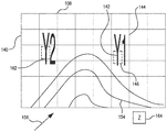
- FIG. 2 is a schematic view of an image acquired by the imaging system of FIG. 1 , showing an image enhanced with a symbol augmenting pulsed illumination appearing in the scene;
- FIG. 3 is a diagram of a method of imaging a scene, e.g., using the imaging device of FIG. 1 to generate the image of FIG. 2 , showing steps of the method.
- FIG. 1 a partial view of an exemplary embodiment of an imaging system in accordance with the disclosure is shown in FIG. 1 and is designated generally by reference character 100 .
- FIGS. 2 and 3 Other embodiments of imaging systems and imaging methods in accordance with the disclosure, or aspects thereof, are provided in FIGS. 2 and 3 , as will be described.
- the imaging systems and imaging methods described herein can be used locating individuals in imaging environments where pulsed illuminating from a locator may not otherwise be readily discernable in an image, such as in imaging difficult terrain or marine environments during search and rescue operations, though the present disclose is not limited to search and rescue operations or any particular type of imaging environment in general.
- Imaging system 100 includes a controller 102 , a memory 104 , and an image and pulse detection array 106 . Imaging system 100 also includes a user interface 108 , one or more locators 110 , and an optional director 112 . In illustrated exemplary embodiment imaging system 100 is carried within a vehicle 10 , which can be manned or unmanned, traversing a scene 12 . It is contemplated that scene 12 can include a marine or terrestrial environment, and that an object of interest 14 be located in scene 12 . Object of interest 14 can be an individual in need of assistance, such as a lost or injured individual that is the subject of a search and rescue mission.
- Controller 102 is operatively connected to image and pulse detection array 106 and director 112 . Controller 102 is also disposed in communication with user interface 108 and memory 104 .
- Memory 104 includes a non-transitory machine-readable medium having a plurality of program modules 130 recorded thereon that, when read by controller 102 , cause controller 102 to execute certain operations. For example, the instructions recorded on memory 104 , when read by controller 102 , cause controller 102 to execute the steps of imaging method 200 (shown in FIG. 3 ), as will be described. It is contemplated that controller 102 be implemented as circuitry, software, or a combination of circuitry, as suitable for an intended application.
- Image and pulse detection array 106 is configured an adapted to generate image data 114 and pulse frequency data 116 using light received from scene 12 .
- image and pulse detection array 106 receives light 18 incident upon and reflected from scene 12 , light 18 originating from a source 20 external to scene 12 , such as the sun, and generates therefrom image data 114 representative of scene 12 .
- Image and pulse detection array 106 also receives pulsed light 22 originating from within scene 12 , and generates therefrom pulse frequency data 116 . It is contemplated that image data 114 and pulse frequency data 116 are acquired using a photodiode array 118 . Examples of suitable pulse detection arrays and photodiode arrays include those described in U.S. patent application Ser. No. 15/266,837, filed on Sep. 15, 2016, the contents of which are incorporated herein by reference in its entirety.
- Light 18 can be ambient illumination, e.g., sunlight. It is contemplated that light 18 can be within a visible waveband, i.e., from within a waveband extending between about 400 nanometers and about 700 nanometers. As will be appreciated by those of skill in the art in view of the present disclosure, light 18 can also be from outside of the visible waveband. For example, light 18 can be from within an infrared waveband, i.e. between about 700 nanometers and about 1 millimeter.
- suitable infrared wavebands include near-infrared (NIR) wavebands, shortwave infrared (SWIR) wavebands, mid-wavelength infrared (MWIR), long-wave infrared LWIR) wavebands, and far-infrared (FIR) wavebands.
- NIR near-infrared
- SWIR shortwave infrared
- MWIR mid-wavelength infrared
- LWIR long-wave infrared
- FIR far-infrared
- NIR wavebands include electromagnetic radiation with wavelengths between about 0.75 and about 1.4 microns; SWIR wavebands includes electromagnetic radiation with wavelengths between about 1.4 micros and about 3 microns; MWIR wavebands include electromagnetic radiation between about 3 microns and about 8 microns; LWIR wavebands include electromagnetic radiation between about 8 microns and about 15 microns; and FIR wavebands include electromagnetic radiation between about 15 microns and about one millimeter.
- Photodiode array 118 is responsive to light 18 to generate image data 114 , from which an image 140 (shown in FIG. 2 ) can be constructed.
- Pulsed light 22 has a predetermined frequency and/or a modulated pulse frequency. Pulsed light 22 originates from a pulsed light source 120 and is also within the visible portion of the electromagnetic spectrum, i.e., within a visible waveband. In certain embodiments pulsed light 22 light generated by a light-emitting-diode (LED) device. LED devices require relatively little power, which increases the time and/or reduces the size of a power source, e.g., power source 122 , powering pulsed light source 120 .
- a power source e.g., power source 122 , powering pulsed light source 120 .
- light 18 can alternatively be from outside of the visible waveband and can be within one or more of the NIR, SWIR, MWIR, LWIR, and FIR wavebands.
- different sub-divisions of the infrared waveband have differing properties that renders them well suited for search and rescue, e.g., frequencies with low water absorption being suited for use in marine applications, etc., improving the distance at which light 18 can be discerned by imaging system 100 .
- Photodiode array 118 is responsive to pulsed light 22 to generate pulse frequency data 116 , from which symbol 142 (shown in FIG. 2 ) is selected.
- Locator 110 is remote from imaging and pulse detection array 106 , e.g., is located within scene 12 , and includes pulsed light source 120 and power source 122 .
- Power source 122 is electrically connected to pulsed light source 120 for providing electrical power to pulsed light source 120 , and can include a battery or solar collection array. It is contemplated that locator 110 be incorporated into a wearable device, hand-held device, a flotation device, a survival suit 124 , or any other suitable device worn or donned by an individual in need of assistance.
- Director 112 is configured for controlling orientation of image and pulse detection array 106 relative to scene 12 and/or vehicle 10 . In this respect director provides one or more of pan, tilt, and zoom capability to image and pulse detection array 106 . In certain embodiments director 112 includes a gimbal movably fixed to vehicle 10 that orients image and pulse detection array according to a selected azimuth and deflection relative to vehicle 10 . Director 112 is configured to provide either or both of gimbal directional data 132 and/or aircraft positional data 134 , which can be used to enhance image 140 (shown in FIG. 2 ).
- User interface 108 is configured for displaying image 140 (shown in FIG. 2 ) and is disposed in communication with imaging system 100 .
- user interface 108 is co-located within imaging system 100 .
- user interface 108 can be arranged within a cockpit of aircraft.
- user interface 108 can be remote (indicated in dashed outline in FIG. 1 ) from imaging system 100 , being located for example in a search and rescue command post, a hand-held device carried by a ground-based search element, or carried in another search aircraft.
- image 140 is shown.
- Image 140 is displayed on user interface 108 (shown in FIG. 1 ) from image data 114 .
- Image 140 is constructed of a plurality of pixels 144 and includes a signal 146 indicative of pulsed light 22 (shown in FIG. 2 ) received form pulsed light source 120 .
- signal 146 is faint.
- signal 146 is not readily discernable to the human eye, i.e., a human observer of image would not readily discern signal 146 .
- signal 146 occupies five or fewer pixels within image 140 , and therefore requires augmentation in order to be reliably discerned by the human eye.
- Image 140 is includes at least one enhancement to make more clear the location of pulsed light source 120 in scene 12 .
- image 140 includes symbol 142 .
- Symbol 142 overlays image 140 in spatial registration with pulsed light source 120 (shown in FIG. 1 ) in scene 12 (shown in FIG. 1 ).
- Symbol 142 makes augments signal 146 , making the location of pulsed light source 120 within scene 12 .
- Symbol 142 is selected according to an association of a frequency 150 (shown in FIG. 1 ) determined from pulse frequency data 116 , which is compared to a listing of frequency/symbol associations 152 recorded on memory 104 , and which imaging system 100 provides to user interface 108 .
- image 140 is additionally enhanced with a map overlay 154 and gimbal directional data and aircraft positional information 156 .
- pulsed light source 120 is a first pulsed light source 120
- symbol 142 is a first symbol 142
- a second light source 160 is augmented with a second symbol 162 .
- Second symbol 162 is similar to first symbol 142 with the difference that second symbol overlays second light source 160 and is selected according to frequency of second light source 160 .
- the pulsed illuminators may pulse at different frequencies so that they can be distinguished from each other.
- a tally 164 is provided image 140 , providing a count of pulsed light sources in scene 12 (shown in FIG. 1 ).
- the image can be further enhanced by displaying tally 164 of the number of symbols appearing in the image.
- Tally 164 as well as the associated geographic location data, can be stored for later review and can provide a headcount of individual(s) in need of rescue, as may be needed when ships are abandoned or in aviation accidents.
- the pulsed illuminators may pulse at different frequencies so that they can be distinguished from each other.
- Method 200 imaging a scene having a pulsed light source, e.g., pulsed light source 120 (shown in FIG. 1 ), as shown with bracket 210 .
- a pulsed light source e.g., pulsed light source 120 (shown in FIG. 1 )
- both non-pulsed light and pulsed light e.g., non-pulsed light 18 (shown in FIG. 1 ) and pulsed light 22 (shown in FIG. 1 )
- Either or both the non-pulsed light and pulsed light can be within a visible waveband, as shown with box 214 .
- Either or both the non-pulsed light and pulsed light can be within an infrared waveband, as shown with box 216 .
- the frequency of the pulsed light source is determined for identifying the source of the pulsed illumination, as shown with box 218 .
- the frequency is compared to a predetermined listing of frequency/symbol associations, as shown with box 220 .
- the frequency/symbol associations may be resident, for example, in a lookup table resident in a program module of a memory, e.g., memory 104 (shown in FIG. 1 ). Based on the comparison a determination is made as to whether the pulsed light source is associated with a locator device, e.g. locator 110 (shown in FIG. 1 ), as shown with decision box 222 .
- the image is communicated to a user interface, as shown with arrow 224 and box 226 .
- the user interface can display the image, as shown with body 228 , and imaging method 200 continue, as shown with arrow 228 .
- a symbol is associated with the pulsed light source, as shown with arrow 232 and box 234 .
- the image is then enhanced with the symbol by inserting the symbol into the image, as shown with box 236 .
- symbols include first symbol 30 (shown in FIG. 2 ), which can be displayed in spatial registration with the pulsed light source in the image to enhance the image.
- overlaying the symbol in the image in spatial registration with the location of the pulsed light source in the scene augments indication of the location provided by the pulsed light source because the pulsed light source may not otherwise be readily discernable to a human observer monitoring the displayed image.
- the present inventors have come to appreciate the pulsed illumination sources occupying five (5) or fewer pixels in an image tend to increase likelihood that a human observer with not discern the source, potentially prolonging a search effort.
- method 200 can include enhancing the image by inserting a map overlay into the image, as shown with box 238 .
- augmented reality mapping techniques enhance features that may not be readily apparent in an image, like roads in forested areas, that otherwise might go unnoticed. This can be advantageous when directing a ground-based search team toward a symbolically indicated location from an aircraft.
- method 200 can include enhancing the image by inserting one or more of gimbal directional data and/or aircraft positional information into the image, as shown with box 240 .
- the gimbal directional data and/or aircraft positional information can be projected such that the real-world geographic location of the pulsed light source is marked on a map.
- the gimbal directional data and/or aircraft positional information can be used to direct the aircraft, ground-based searchers, or other aircraft, toward the location of the pulsed light source.
- imaging devices with imaging and pulse detection arrays are employed to detect lost and/or incapacitated individuals in a search and rescue situation.
- Imaging and pulse detection arrays can provide the ability to reliably detect pulsed light sources in situations where an imaging array could otherwise not reliably detect the pulsed light source. For example, in images where a pulsed light source fills five (5) or fewer pixels, the human eye may not take notice the signal associated with the pulsed light source.
- frequency data generated by the imaging and pulse detection array is used to identify pulsed light sources in a scene being imaged and overlay an image of the scene with a symbol, e.g., symbol 142 (shown in FIG. 2 ).
- the symbol enhances the location of the pulsed light source within the image, making signals indicative of the location of a lost and/or incapacitated individual in the image readily discernable to the human eye. It is contemplated that the location of the pulsed light source can be enhanced when the pulsed light source is faint.
- the symbol enhances the image with the location of the pulsed illumination in the image.
- the symbol enhances the image with the location of the pulsed light source in the image. In each case the symbol makes it more difficult for an observer to overlook the pulsed light source in the image.
- augmented reality mapping can be employed.
- image data, with the symbol when a pulsed light source is determined to be present in a scene is further enhanced with mapping information, e.g., mapping information 154 (shown in FIG. 2 ).
- the mapping information can be inserted in the image with the symbol in spatial registration with the scene, thereby providing mapping information in association with the symbol and image the surrounding scene.
- the image data can be enhanced with either or both of gimbal directional data and vehicular positional data, e.g., aircraft global positioning system (GPS) data, as shown in FIG. 2 with reference numeral 156 .
- GPS global positioning system
- the image data, enhanced with geo-positional information can be communicated to other search assets, like a search command post, ground search teams, other search aircraft, or watercraft participating in the search.
- the present disclosure provides a small, compact, and highly reliable method for rapidly searching wide swaths of terrain or marine environments.
- This invention enables the detection and accounting of lost or incapacitated individual(s) when traditional search methods fail, such as when the searchers are searching from high above the lost individual(s) and when other optical signals that indicate the location of the lost individual(s) are difficult to distinguish from the background with existing tech.
Abstract
Description
Claims (17)
Priority Applications (1)
| Application Number | Priority Date | Filing Date | Title |
|---|---|---|---|
| US15/672,045 US10587824B2 (en) | 2017-08-08 | 2017-08-08 | Imaging systems with pulse detection for search and rescue |
Applications Claiming Priority (1)
| Application Number | Priority Date | Filing Date | Title |
|---|---|---|---|
| US15/672,045 US10587824B2 (en) | 2017-08-08 | 2017-08-08 | Imaging systems with pulse detection for search and rescue |
Publications (2)
| Publication Number | Publication Date |
|---|---|
| US20190052818A1 US20190052818A1 (en) | 2019-02-14 |
| US10587824B2 true US10587824B2 (en) | 2020-03-10 |
Family
ID=65274319
Family Applications (1)
| Application Number | Title | Priority Date | Filing Date |
|---|---|---|---|
| US15/672,045 Active 2037-12-04 US10587824B2 (en) | 2017-08-08 | 2017-08-08 | Imaging systems with pulse detection for search and rescue |
Country Status (1)
| Country | Link |
|---|---|
| US (1) | US10587824B2 (en) |
Families Citing this family (1)
| Publication number | Priority date | Publication date | Assignee | Title |
|---|---|---|---|---|
| US20230326333A1 (en) * | 2022-03-22 | 2023-10-12 | Sheaumann Laser, Inc. | Fingerprint modulation for beacon |
Citations (8)
| Publication number | Priority date | Publication date | Assignee | Title |
|---|---|---|---|---|
| US5270780A (en) | 1991-09-13 | 1993-12-14 | Science Applications International Corporation | Dual detector lidar system and method |
| US20110233409A1 (en) * | 2010-03-25 | 2011-09-29 | Weida Miles J | Quantum cascade laser that generates widely viewable mid-infrared light |
| US20140267723A1 (en) * | 2013-01-30 | 2014-09-18 | Insitu, Inc. | Augmented video system providing enhanced situational awareness |
| US20150092179A1 (en) | 2012-05-12 | 2015-04-02 | Izak Jan van Cruyningen | Light ranging with moving sensor array |
| US20160370226A1 (en) | 2015-03-30 | 2016-12-22 | Sensors Unlimited, Inc. | Digital imaging and pulse detection pixel |
| US9568583B2 (en) | 2013-06-21 | 2017-02-14 | Rosemount Aerospace Inc. | Asynchronous pulse detection through sequential time sampling of optically spread signals |
| US20170064235A1 (en) | 2015-08-27 | 2017-03-02 | Samsung Electronics Co., Ltd. | Epipolar plane single-pulse indirect tof imaging for automotives |
| US20180005503A1 (en) * | 2015-01-13 | 2018-01-04 | Robert Kaindl | Personal safety device, method and article |
-
2017
- 2017-08-08 US US15/672,045 patent/US10587824B2/en active Active
Patent Citations (8)
| Publication number | Priority date | Publication date | Assignee | Title |
|---|---|---|---|---|
| US5270780A (en) | 1991-09-13 | 1993-12-14 | Science Applications International Corporation | Dual detector lidar system and method |
| US20110233409A1 (en) * | 2010-03-25 | 2011-09-29 | Weida Miles J | Quantum cascade laser that generates widely viewable mid-infrared light |
| US20150092179A1 (en) | 2012-05-12 | 2015-04-02 | Izak Jan van Cruyningen | Light ranging with moving sensor array |
| US20140267723A1 (en) * | 2013-01-30 | 2014-09-18 | Insitu, Inc. | Augmented video system providing enhanced situational awareness |
| US9568583B2 (en) | 2013-06-21 | 2017-02-14 | Rosemount Aerospace Inc. | Asynchronous pulse detection through sequential time sampling of optically spread signals |
| US20180005503A1 (en) * | 2015-01-13 | 2018-01-04 | Robert Kaindl | Personal safety device, method and article |
| US20160370226A1 (en) | 2015-03-30 | 2016-12-22 | Sensors Unlimited, Inc. | Digital imaging and pulse detection pixel |
| US20170064235A1 (en) | 2015-08-27 | 2017-03-02 | Samsung Electronics Co., Ltd. | Epipolar plane single-pulse indirect tof imaging for automotives |
Also Published As
| Publication number | Publication date |
|---|---|
| US20190052818A1 (en) | 2019-02-14 |
Similar Documents
| Publication | Publication Date | Title |
|---|---|---|
| CN103583037B (en) | Infrared camera systems and methods | |
| US10395113B2 (en) | Polarization-based detection and mapping method and system | |
| US6373055B1 (en) | Enhanced vision system sensitive to infrared radiation | |
| US6678395B2 (en) | Video search and rescue device | |
| EP1989681B1 (en) | System for and method of synchronous acquisition of pulsed source light in performance of monitoring aircraft flight operation | |
| US8749635B2 (en) | Infrared camera systems and methods for dual sensor applications | |
| Rivera et al. | Post-disaster rescue facility: Human detection and geolocation using aerial drones | |
| EP2628019B1 (en) | Search and rescue using ultraviolet radiation | |
| US10621438B2 (en) | Hybrid hyperspectral augmented reality device | |
| US10803590B2 (en) | Multiple-wavelength images analysis electro optical system for detection of accident ship and submerged person and analysis method thereof | |
| US20220301303A1 (en) | Multispectral imaging for navigation systems and methods | |
| US20220291701A1 (en) | Thermal imaging for navigation systems and methods | |
| US20220214222A1 (en) | Radiometric thermal imaging improvements for navigation systems and methods | |
| US6335526B1 (en) | Infrared sensor system technique | |
| EP3631391A1 (en) | Polarization-based detection and mapping method and system | |
| US10587824B2 (en) | Imaging systems with pulse detection for search and rescue | |
| Larochelle et al. | Two generations of Canadian active imaging systems: ALBEDOS and ELVISS | |
| US11263911B2 (en) | Systems and methods for identifying air traffic objects | |
| US11967104B1 (en) | Method for determining the actual location of an object in a camera field of view | |
| EP4067814A1 (en) | Radiometric thermal imaging improvements for navigation systems and methods | |
| US20240103154A1 (en) | Location Apparatus | |
| Castaldo et al. | Evaluation of FLIR/IR camera technology for airport surface surveillance | |
| JP6561425B1 (en) | Optical search system | |
| Hema et al. | Infrared-Imaging Enabled Drone for the Detection of Infiltrators and Concealed Weapons | |
| Miller et al. | Fiber-optic-coupled gimballed laser spotlight |
Legal Events
| Date | Code | Title | Description |
|---|---|---|---|
| AS | Assignment |
Owner name: SENSORS UNLIMITED, INC., NEW JERSEY Free format text: ASSIGNMENT OF ASSIGNORS INTEREST;ASSIGNORS:DVONCH, CURT;ALLARD, ALBERT P.;REEL/FRAME:043470/0728 Effective date: 20170803 |
|
| STPP | Information on status: patent application and granting procedure in general |
Free format text: PRE-INTERVIEW COMMUNICATION MAILED |
|
| STPP | Information on status: patent application and granting procedure in general |
Free format text: RESPONSE TO NON-FINAL OFFICE ACTION ENTERED AND FORWARDED TO EXAMINER |
|
| STPP | Information on status: patent application and granting procedure in general |
Free format text: NON FINAL ACTION MAILED |
|
| STPP | Information on status: patent application and granting procedure in general |
Free format text: RESPONSE TO NON-FINAL OFFICE ACTION ENTERED AND FORWARDED TO EXAMINER |
|
| STPP | Information on status: patent application and granting procedure in general |
Free format text: NOTICE OF ALLOWANCE MAILED -- APPLICATION RECEIVED IN OFFICE OF PUBLICATIONS |
|
| STPP | Information on status: patent application and granting procedure in general |
Free format text: PUBLICATIONS -- ISSUE FEE PAYMENT RECEIVED |
|
| STCF | Information on status: patent grant |
Free format text: PATENTED CASE |
|
| MAFP | Maintenance fee payment |
Free format text: PAYMENT OF MAINTENANCE FEE, 4TH YEAR, LARGE ENTITY (ORIGINAL EVENT CODE: M1551); ENTITY STATUS OF PATENT OWNER: LARGE ENTITY Year of fee payment: 4 |