US10587293B2 - Method for improving signal to noise ratio in an uplink transmission - Google Patents
Method for improving signal to noise ratio in an uplink transmission Download PDFInfo
- Publication number
- US10587293B2 US10587293B2 US15/767,356 US201715767356A US10587293B2 US 10587293 B2 US10587293 B2 US 10587293B2 US 201715767356 A US201715767356 A US 201715767356A US 10587293 B2 US10587293 B2 US 10587293B2
- Authority
- US
- United States
- Prior art keywords
- users
- signal
- combinations
- base station
- antennas
- Prior art date
- Legal status (The legal status is an assumption and is not a legal conclusion. Google has not performed a legal analysis and makes no representation as to the accuracy of the status listed.)
- Active
Links
- 238000000034 method Methods 0.000 title claims abstract description 79
- 230000005540 biological transmission Effects 0.000 title claims abstract description 53
- 239000011159 matrix material Substances 0.000 claims description 134
- 239000013598 vector Substances 0.000 claims description 77
- 238000000354 decomposition reaction Methods 0.000 claims description 11
- 238000004364 calculation method Methods 0.000 claims description 10
- 239000002585 base Substances 0.000 description 319
- 108091006146 Channels Proteins 0.000 description 125
- 210000004027 cell Anatomy 0.000 description 73
- 238000004422 calculation algorithm Methods 0.000 description 40
- 230000006870 function Effects 0.000 description 36
- 238000005314 correlation function Methods 0.000 description 15
- 238000004891 communication Methods 0.000 description 12
- 238000012545 processing Methods 0.000 description 12
- 238000004088 simulation Methods 0.000 description 9
- 239000000654 additive Substances 0.000 description 6
- 230000000996 additive effect Effects 0.000 description 6
- 210000004460 N cell Anatomy 0.000 description 5
- 230000002452 interceptive effect Effects 0.000 description 5
- 230000000116 mitigating effect Effects 0.000 description 4
- 239000004032 superbase Substances 0.000 description 4
- 150000007525 superbases Chemical class 0.000 description 4
- 238000005516 engineering process Methods 0.000 description 3
- 230000003595 spectral effect Effects 0.000 description 3
- PCTMTFRHKVHKIS-BMFZQQSSSA-N (1s,3r,4e,6e,8e,10e,12e,14e,16e,18s,19r,20r,21s,25r,27r,30r,31r,33s,35r,37s,38r)-3-[(2r,3s,4s,5s,6r)-4-amino-3,5-dihydroxy-6-methyloxan-2-yl]oxy-19,25,27,30,31,33,35,37-octahydroxy-18,20,21-trimethyl-23-oxo-22,39-dioxabicyclo[33.3.1]nonatriaconta-4,6,8,10 Chemical group C1C=C2C[C@@H](OS(O)(=O)=O)CC[C@]2(C)[C@@H]2[C@@H]1[C@@H]1CC[C@H]([C@H](C)CCCC(C)C)[C@@]1(C)CC2.O[C@H]1[C@@H](N)[C@H](O)[C@@H](C)O[C@H]1O[C@H]1/C=C/C=C/C=C/C=C/C=C/C=C/C=C/[C@H](C)[C@@H](O)[C@@H](C)[C@H](C)OC(=O)C[C@H](O)C[C@H](O)CC[C@@H](O)[C@H](O)C[C@H](O)C[C@](O)(C[C@H](O)[C@H]2C(O)=O)O[C@H]2C1 PCTMTFRHKVHKIS-BMFZQQSSSA-N 0.000 description 2
- 101100366000 Caenorhabditis elegans snr-1 gene Proteins 0.000 description 2
- 230000015556 catabolic process Effects 0.000 description 2
- 230000001413 cellular effect Effects 0.000 description 2
- 230000007423 decrease Effects 0.000 description 2
- 238000006731 degradation reaction Methods 0.000 description 2
- 230000006872 improvement Effects 0.000 description 2
- 230000000670 limiting effect Effects 0.000 description 2
- 238000012986 modification Methods 0.000 description 2
- 230000004048 modification Effects 0.000 description 2
- 230000008569 process Effects 0.000 description 2
- 230000002829 reductive effect Effects 0.000 description 2
- 230000004075 alteration Effects 0.000 description 1
- 230000003247 decreasing effect Effects 0.000 description 1
- 238000010586 diagram Methods 0.000 description 1
- 238000002474 experimental method Methods 0.000 description 1
- 230000007774 longterm Effects 0.000 description 1
- 238000013507 mapping Methods 0.000 description 1
- 239000000463 material Substances 0.000 description 1
- 230000036961 partial effect Effects 0.000 description 1
- 230000009467 reduction Effects 0.000 description 1
Images


Classifications
-
- H—ELECTRICITY
- H04—ELECTRIC COMMUNICATION TECHNIQUE
- H04B—TRANSMISSION
- H04B1/00—Details of transmission systems, not covered by a single one of groups H04B3/00 - H04B13/00; Details of transmission systems not characterised by the medium used for transmission
- H04B1/02—Transmitters
- H04B1/04—Circuits
- H04B1/0475—Circuits with means for limiting noise, interference or distortion
-
- H—ELECTRICITY
- H04—ELECTRIC COMMUNICATION TECHNIQUE
- H04B—TRANSMISSION
- H04B1/00—Details of transmission systems, not covered by a single one of groups H04B3/00 - H04B13/00; Details of transmission systems not characterised by the medium used for transmission
- H04B1/06—Receivers
- H04B1/10—Means associated with receiver for limiting or suppressing noise or interference
-
- H—ELECTRICITY
- H04—ELECTRIC COMMUNICATION TECHNIQUE
- H04B—TRANSMISSION
- H04B1/00—Details of transmission systems, not covered by a single one of groups H04B3/00 - H04B13/00; Details of transmission systems not characterised by the medium used for transmission
- H04B1/62—Details of transmission systems, not covered by a single one of groups H04B3/00 - H04B13/00; Details of transmission systems not characterised by the medium used for transmission for providing a predistortion of the signal in the transmitter and corresponding correction in the receiver, e.g. for improving the signal/noise ratio
-
- H—ELECTRICITY
- H04—ELECTRIC COMMUNICATION TECHNIQUE
- H04B—TRANSMISSION
- H04B1/00—Details of transmission systems, not covered by a single one of groups H04B3/00 - H04B13/00; Details of transmission systems not characterised by the medium used for transmission
- H04B1/69—Spread spectrum techniques
- H04B1/707—Spread spectrum techniques using direct sequence modulation
- H04B1/7097—Interference-related aspects
- H04B1/7103—Interference-related aspects the interference being multiple access interference
- H04B1/7107—Subtractive interference cancellation
- H04B1/71075—Parallel interference cancellation
-
- H—ELECTRICITY
- H04—ELECTRIC COMMUNICATION TECHNIQUE
- H04B—TRANSMISSION
- H04B17/00—Monitoring; Testing
- H04B17/30—Monitoring; Testing of propagation channels
- H04B17/309—Measuring or estimating channel quality parameters
- H04B17/336—Signal-to-interference ratio [SIR] or carrier-to-interference ratio [CIR]
-
- H—ELECTRICITY
- H04—ELECTRIC COMMUNICATION TECHNIQUE
- H04B—TRANSMISSION
- H04B7/00—Radio transmission systems, i.e. using radiation field
- H04B7/02—Diversity systems; Multi-antenna system, i.e. transmission or reception using multiple antennas
- H04B7/04—Diversity systems; Multi-antenna system, i.e. transmission or reception using multiple antennas using two or more spaced independent antennas
- H04B7/0413—MIMO systems
- H04B7/0456—Selection of precoding matrices or codebooks, e.g. using matrices antenna weighting
-
- H—ELECTRICITY
- H04—ELECTRIC COMMUNICATION TECHNIQUE
- H04J—MULTIPLEX COMMUNICATION
- H04J11/00—Orthogonal multiplex systems, e.g. using WALSH codes
- H04J11/0023—Interference mitigation or co-ordination
- H04J11/0026—Interference mitigation or co-ordination of multi-user interference
- H04J11/003—Interference mitigation or co-ordination of multi-user interference at the transmitter
-
- H—ELECTRICITY
- H04—ELECTRIC COMMUNICATION TECHNIQUE
- H04W—WIRELESS COMMUNICATION NETWORKS
- H04W72/00—Local resource management
- H04W72/12—Wireless traffic scheduling
- H04W72/121—Wireless traffic scheduling for groups of terminals or users
Definitions
- the subject matter in general relates to LTE network systems. More particularly, but not exclusively, the subject matter is directed to reduction of interference and improvement of signal strength in an LTE system.
- LTE Long-Term Evolution
- CPU Central Processing Unit
- the radio uplink is the transmission path from the mobile station (cell phone) to a base station (cell site).
- Physical uplink shared channel is used to carry the uplink user's information data.
- SNR Signal to Noise Ratio
- signals from one user in one subcarrier face interference from the signals from the other users in the same subcarrier which decreases the network throughput of the wireless network systems.
- MIMO Multiple Input Multiple Output
- MIMO systems use more than one transmit antenna to send a signal on the same frequency to more than one receiving antenna.
- This technology provides LTE with the ability to further improve its data throughput. Although, it enables far high data rates to be achieved but ends up adding complexity to the system in terms of processing and the number of antennas required.
- the available data throughput is shared among them. Different users will typically place different throughput demands on a LTE base station at a given time, but at times when the aggregate throughput demands exceed the available throughput from the LTE base station to the users, then some or all users will receive less data throughput than they are seeking.
- a method for improving signal to noise ratio in an uplink transmission.
- SNR signal to noise ratio
- a method for improving signal to noise ratio in an uplink transmission.
- a method for improving signal to noise ratio in an uplink transmission.
- a method for accommodating multiple users transmitting on a same sub-carrier to a base station comprising n antennas.
- the method includes enabling a first user to transmit two bits through two antennas of a user equipment of the first user; decomposing a (n ⁇ 2) channel matrix of the first user using Singular Value Decomposition (SVD), into three matrices, wherein the matrices are a (n ⁇ n) unitary matrix which is denoted by “U”, a (n ⁇ 2) partial diagonal matrix which is denoted by “S” and a precoder (2 ⁇ 2) unitary matrix which is denoted by “V H ”; enabling other (n ⁇ 2) users in the base station to transmit one data bit each through two antennas to the base station on same sub-carrier as the first user; computing effective channel matrix of the first user; computing effective channel vectors of the (n ⁇ 2) users using “U”; computing transmit precoders of the (n ⁇ 2) users using “U”; and computing signal to noise ratio and decoding
- a method for accommodating multiple users transmitting on a same sub-carrier to a base station comprising n antennas.
- FIG. 1 is a block diagram of a system 100 for improving signal to noise ratio in an uplink transmission
- FIG. 2A is a flowchart 220 which illustrates a first exemplary method for improving the SNR of signals in an uplink transmission
- FIG. 2B is a first exemplary system 200 , comprising 1 Cell, 1 Base station (BS), many users/BS and 1 Antenna/User, for improving the SNR of signals in an uplink transmission;
- BS Base station
- Antenna/User for improving the SNR of signals in an uplink transmission
- FIG. 3A is a flowchart 320 which illustrates a second exemplary method for improving the SNR of signals in an uplink transmission
- FIG. 3B is a second exemplary system 300 comprising, N cells, N Base stations (BS), 1 User/BS and 1 Antenna/User, for improving the SNR of signals in an uplink transmission;
- BS Base stations
- 1 User/BS User/BS
- Antenna/User for improving the SNR of signals in an uplink transmission
- FIG. 4A is a flowchart 420 which illustrates third exemplary method for improving the SNR of signals in an uplink transmission
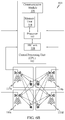
- FIG. 4B is third exemplary system 400 , comprising N cells, N Base stations (BS), 1 User/BS, 2 Antennas/User, for improving the SNR of signals in an uplink transmission;
- BS Base stations
- 1 User/BS User/BS
- 2 Antennas/User for improving the SNR of signals in an uplink transmission
- FIG. 5A is a flowchart 550 which illustrates a method for mitigating the loss in an uplink transmission and increase the overall signal to noise ratio;
- FIG. 5B is an exemplary system 500 , comprising 1 Cell, 1 Base station (BS), many users/BS and 2 antennas/User, for selecting the best possible users in a cell;
- BS Base station
- FIG. 5B is an exemplary system 500 , comprising 1 Cell, 1 Base station (BS), many users/BS and 2 antennas/User, for selecting the best possible users in a cell;
- FIG. 5C is a flowchart 516 which illustrates a method for selecting the best possible users to be accommodated in a cell
- FIG. 5D is another exemplary system 560 , comprising 1 Cell, 1 Base station (BS), many users/BS and 2 antennas/User, for selecting the best users to be accommodated in a cell;
- BS Base station
- FIG. 5D is another exemplary system 560 , comprising 1 Cell, 1 Base station (BS), many users/BS and 2 antennas/User, for selecting the best users to be accommodated in a cell;
- FIG. 5E is a tree structure representing possible combination of users in a subset
- FIG. 6A is a flowchart 620 which illustrates a method of selecting antennas of the N base stations 110 ;
- FIG. 6B is an exemplary system 600 , comprising N cells, N base stations (BS), 1 User/BS and 1 Antenna/User, for selecting the best set of antennas for the users;
- FIG. 7 is a flowchart 700 which illustrates an exemplary method to estimate the channel values of M users across N subcarriers
- FIG. 8 illustrates a simulation output for the first exemplary system 200 .
- FIG. 9 illustrates a simulation output for the second exemplary system 300 .
- FIG. 10 illustrates a simulation output for the third exemplary system 400 .
- FIG. 11 illustrates a simulation output for accommodating more users in a cell.
- bits may mean symbols as in constellation mapping in digital communications.
- Embodiments provide a system and method for improving strength of signals in uplink transmission. Embodiments, further, provide methods for increasing the overall spectral efficiency in an uplink transmission.
- the system includes a processor which communicates with the base stations. The processor is configured to process the received signals in order to improve the SNR of the signals.
- the system includes a memory unit, communication module, and an IRC unit. The IRC unit is responsible for computing the signal to noise ratio of the uplink signals received at one or more antennas of one or more base station in the system.
- the IRC unit is configured to compute signal to noise ratio (SNR) of the signals received from each of the users among the determined combinations of N possible users and selecting at least one combination among the plurality of combinations of N possible users.
- the combination is selected, such that, a consolidated signal to noise ratio of the selected combination is maximum among all combinations.
- Methods are provided for efficiently computing the SNR of the signals received at the antennas of the base station.
- the IRC unit is configured to compute signal to noise ratio for at least a predetermined number of users in one or more of the combination of N possible users.
- the calculated signal to noise ratio for the predetermined number of users are recorded in the memory unit of the system.
- signal to noise ratios which are calculated previously, are used in the calculation of SNRs of the subsequent combinations of N possible users. Methods are provided for increasing the performance of the user equipment's communicating to the base stations. Furthermore, to elevate the network capacity i.e. the number of users for the network is equally taken into consideration.
- the uplink shared channel is used to carry the uplink's information data over a subcarrier.
- the processor determines the best user to be selected among all the user communicating to the base station at the same time which can be allowed for the transmission without interfering with the communication of the other users.
- the system makes use of simplified algorithms which increases the processing and elevates overall throughput of the network mitigating the loss which can be caused by the interference when the user equipment's are communicating to the base station at the same time.
- Embodiments provide methods for selecting the best possible antennas of the base stations.
- Embodiments further provide methods for estimating the channel values of the user equipment's if they occur to carry out the uplink transmission over “N” number of subcarriers. While considering the transmission across the set of subcarriers, the reception of the data at each subcarrier will be the summation of the transmission by the all user equipment's.
- the processor estimates the channel values of each user equipment's for the given output signal received at base station where channel values vary when transmitted over “N” number of subcarriers.
- FIG. 1 an exemplary architecture of an exemplary system 100 for improving signal to noise ratio in an uplink transmission.
- the system components/modules are discussed.
- the system 100 includes, but not limited to, a processor 102 , a memory unit 104 and a network communication module 106 .
- System 100 may further include an interference rejection combining unit 108 or an IRC unit 108 .
- System 100 may include provisions for receiving signals from a plurality of base stations 110 of cellular networks, wherein base stations may belong to one or more small cells. Base stations 110 may be included as part of the system 100 .
- the system 100 may further include a memory unit 104 , wherein the memory unit 104 is configured to store or keep records of the computations which aids in further computations and making the processing much faster.
- a communication interface may be present which helps to communicate with the plurality of the base stations.
- a Central Processing Unit (CPU) 112 includes, but not limited to, the processor 102 , the memory unit 104 , the communication module 106 , the IRC unit 108 .
- the communication module(s) 106 may interact with base stations 110 and all the base stations may be connected to the Central Processing Unit where the received signals are processed.
- There may be multiple communication modules in the Central Processing Unit (CPU) 112 which may communicate to plurality of base stations ( 110 ) which may further communicate to the Central Processing Unit (CPU) 112 .
- processor 102 returns output by accepting signals, such as electrical signals as input.
- processor 102 may include one or more processing units
- Processor(s) may be implemented as appropriate in hardware, computer-executable instructions, firmware, or combinations thereof.
- Computer-executable instruction or firmware implementations of the processor 102 may include computer-executable or machine-executable instructions written in any suitable programming language to perform the various functions described.
- the memory units/devices 104 may store data and program instructions that are loadable and executable on processor(s) 102 as well as data generated during the execution of these programs.
- the memory may be volatile, such as random-access memory and/or a disk drive or non-volatile memory.
- One or more base stations 110 from one or more cells may be configured to communicate with the processor 102 . Communication is enabled by the communication module 106 .
- the processor 102 receives signals from the base stations 110 and communicates the signals to the IRC unit 108 , where the interference of the received signal is suppressed and the signal to noise ratio (SNR) is maximized.
- SNR signal to noise ratio
- the IRC unit 108 is configured to receive instructions from the processor 102 .
- the IRC unit 108 is configured to emulate interferences occurring from one or more user equipments (mobile communicating devices) transmitting data bits using multiple channels.
- the IRC unit 108 utilizes the characteristics of inter-cell interference to determine the power of the interfering user equipment's which belongs to another cell. Once the pattern and power level is determined, the interfering signal can be reduced/removed from the received signals of the desired user equipment.
- the IRC unit 108 is further configured to maximize the signal to noise ration of the received signals.
- IRC unit 108 receives instructions from the processor 102 to suppress interference while maximizing signal to noise ratio (SNR) of the received signals.
- SNR signal to noise ratio
- the IRC unit 108 of the system 100 is configured to estimate the input data bits (signals) received from user equipments at the antennas of the base stations 110 .
- the signals received at the antennas of the base stations 110 may be communicated to the processor 102 , where the processor 102 instructs the IRC unit 108 to estimate the input data signal using a Hermitian function.
- the second function expresses the input data signal “x” as a product of a Hermitian Matrix “W H ” and a received signal “Y” at all the antennas of base station 110 as shown below.
- the IRC unit 108 of the system 100 is further configured to compute the Hermitian Matrix “W H ” using a Hermitian function as shown below.
- the IRC unit 108 of the system 100 is further configured to compute the SNR of the uplink signal which is mentioned in detail in the later concepts pertaining to computing the signal to noise ratios (SNR). The method to improve the signal to noise ratio in different scenarios is explained in detail in further descriptions.
- a flowchart 220 illustrates an exemplary method for improving the SNR of signals in an uplink transmission.
- method for improving the SNR of signals in an uplink transmission illustrated in flowchart 220 involves one small cell, one base station within the cell and “X” users (users may refer to user equipment's) associated to the base station.
- the processor 102 may be configured to select “N” users among X users for which the SNR will be calculated. There are about X C N possible combination of N users.
- the number of “N” user equipment's may be equal to the “n” number of antennas.
- Each of the N users transmits signal through one vector channel, hence N users transmits using N vector channels.
- the channel is expressed as a vector comprising one column and n rows corresponding to one user equipment to “n” antennas.
- Each user transmits uplink signals to base stations on the same frequency subcarrier.
- Each of the user equipment's may include one transmitting antenna.
- the processor 102 determines a plurality of combinations of N possible users to be selected among X users that are transmitting signals through N vector channel to a base station comprising n number of antennas.
- input data signal is determined from the N channels and the signals received at the “n” antennas of the base station using an Interference Rejection Combining (IRC) function.
- the IRC function may be carried out in the IRC unit 108 .
- the IRC unit 108 determines a matrix of the channel value using a Hermitian function.
- the Hermitian function may be a function that computes a Hermitian Matrix from the channel vector, where the channel vector is a matrix comprising one column and n rows.
- the output matrix of the Hermitian function or the Hermitian matrix may be an n column and one row matrix.
- the IRC unit 108 calculates the input data signal using the received signal and the matrix obtained using the IRC function on the channel value and the signal to noise ratio (SNR) using the channel vector.
- the IRC unit 108 calculates the SNR of all users among the determined combination of N possible users.
- the processor 102 selects at least one combination of N users among the plurality of combinations of N possible users, such that, the N th root of the product of the signal to noise ratios (SNR) of the selected N users is maximum among all combinations.
- FIG. 2B illustrates a system 100 including one cell and one base station within the cell.
- the base station 110 comprises 4 antennas (not shown) in the figure.
- the base station 110 may be associated with 10 users.
- the processor 102 may be configured to select at least 4 users among the 10-user equipment's, such that each of the 4 users transmits through one vector channel to all the 4 antennas of the base station 110 at the same time on the same subcarrier.
- the processor 102 instructs the IRC unit 108 to estimate the input data signal using a second function.
- the base station may receive 4 bits of data at each antenna through 4 scalar channels such that one user equipment transmits 1 bit of data.
- the users be denoted by “i”, “j”, “k”, “l” such that the selected users are the i th , j th , k th and the l th users in the base station 110 .
- input signal transmitted by the j th user be x j
- input signal transmitted by the k th user be x k
- input signal transmitted by the l th user be x l .
- the output signal received at all the four antennas of base station 110 be Y.
- the IRC function expresses the input data signals “x i ” as the product of a Hermitian Matrix “W i H ” and a received signal Y, “x j ” as the product of a Hermitian Matrix “W j H ” and a received signal Y, “x k ” as the product of a Hermitian Matrix “W k H ” and a received signal Y and “x l ” as the product of a Hermitian Matrix “W l H ” and a received signal “Y” across all the four antennas of the base station 110 as shown below.
- the IRC unit 108 of the system 100 is further configured to compute the Hermitian matrices “W i H ”, W j H , W k H and W l H using the first function as shown below.
- W i H h i H R i ⁇ 1
- W j H h j H R j ⁇ 1
- W k H h k H R k ⁇ 1
- W l H h l H R l ⁇ 1
- the 4 channels used by the 4 users be denoted by h i , h j , h k , h l corresponding to all the “n” antennas comprising n rows and one column.
- the SNRs of the signals received from user equipments of the “i”, “j”, “k” and “l” users are respectively denoted by SNR i , SNR j , SNR k and SNR l .
- SNR i h i H R i ⁇ 1 h i
- R i h j h j H +h k h k H +h l h l H + ⁇ 2
- SNR j h j H R j ⁇ 1 h j
- R j h i h i H +h k h k H +h l h l H + ⁇ 2
- SNR k h k H R k ⁇ 1 h k
- R l h i h i H +h j h j H +h l h l H + ⁇ 2
- I SNR l h l H R l ⁇ 1 h l
- R l h i h i H +h j h
- the processor 102 is configured to calculate SNRs of each user among the 4 possible users in the 210 combinations.
- the processor 102 selects at least one combination of 4 users among the plurality of 210 combinations of 4 possible users, such that, the 4 th root of the product of the signal to noise ratios (SNR i , SNR j , SNR k and SNR l ) of the selected 4 users is maximum among all combinations.
- SNR i , SNR j , SNR k and SNR l signal to noise ratios
- SNR i ⁇ SNR j ⁇ SNR k ⁇ SNR l 4 is maximum among all combinations.
- the processor 102 is further configured to calculate signal to noise ratio for at least a predetermined number of users in one or more of the plurality of combinations of N users. For example, the processor 102 may calculate SNRs of at least the i th user and the j th user in the 210 combinations of 4 users. In other words, the processor 102 may calculate SNR i , SNR j to begin with. Further, the processor 102 may be configured to reuse or utilize the computations used for the previously calculated SNRs to compute
- SNR i ⁇ SNR j ⁇ SNR k ⁇ SNR l 4 in the subsequent combinations of N possible users.
- the calculated SNRs are stored within the memory unit 104 of system 100 .
- the above computations are carried out using Woodbury's identity algorithm. A method to compute the signal to noise ratios for the selected users is explained in detail in later concept.
- a simulation result for a system comprising a base station comprising 4 antennas wherein each user equipment comprises one antenna.
- 4 user equipments are selected from 20 user equipments in 20 C 4 ways.
- the sum SINR of all users in each combination is plotted. As it clearly depicts the sum SINR (refers to SNR) varies from a minimum of 7 dB to a maximum of 30 db. Therefore, it becomes necessary to select the best combination of 4 user equipments in an intelligent way using less complexity.
- a flowchart 320 illustrates an exemplary method for improving the SNR of signals in an uplink transmission.
- method for improving the SNR of signals in an uplink transmission illustrated in flowchart involves N small cells, N base stations 110 and “X” users transmitting to the base stations 110 .
- the processor 102 may be configured to select “N” users among X users (users may also refer to user equipment's) such that one user is selected in each cell (X user equipment's may be distributed equally among N cells). There are about (X/N) N possible combinations of N user equipment's. It may be noted that processor 102 determines the plurality of combinations of N possible users among the X users using (X 1 *X 2 . . .
- the number of “N” user equipment's may be equal to the “n” number of antennas.
- Each of the N users transmits signals through n*N scalar channels to all the to n*N antennas of all the base stations 110 .
- the channel is expressed as a vector comprising one column and n*N rows. All the user equipments transmit uplink signals to base stations 110 at same frequency subcarrier.
- the processor 102 determines a plurality of combinations of N possible users to be selected among X users that are transmitting signals through n*N channels to N base stations comprising n number of antennas.
- X users are associated with a plurality of base stations 110 .
- the processor 102 determines a plurality of combinations of N possible users to be selected among the X users, such that each of the N users transmits to all the base stations, each base station comprising n number of antennas.
- the IRC unit 108 determines input data signal of each user equipment by processing signals at each of the n*N antennas of the all the base stations using the IRC function.
- Each channel value is a single column and n*N row matrix and received signal is a single column and n*N row matrix.
- the IRC unit 108 determines a matrix of the channel using the IRC function, wherein the matrix is a n*N row and single column matrix.
- the IRC unit 108 calculates the input data signal and the signal to noise ratio using the received signal and the n*N row and single column matrix.
- the IRC unit 108 calculates the SNR of all user equipment's among the determined combination of N possible users.
- the processor 102 selects at least one combination of N users among the plurality of combinations of N possible users, such that, the N th root of the product of the signal to noise ratios (SNR) of the selected N users is maximum among all combinations.
- SNR signal to noise ratios
- FIG. 3B illustrates a system 300 including 4 cells and 4 base stations, such that one base station 110 belongs to one cell.
- the system 300 comprises 4 cells say Cell 1 , Cell 2 , Cell 3 and Cell 4 .
- Each cell comprises a base station, let's assume there are 4 base stations for 4 cells, say 110 a , 110 b , 110 c and 110 d for Cell 1 , Cell 2 , Cell 3 and Cell 4 respectively.
- Each base station comprises 4 antennas (not shown) in figure.
- the base stations 110 a , 110 b , 110 c and 110 d may be associated with about 10 users in each cell.
- Each user in one cell may also transmit to all other base station in the other cells.
- There may be 10 4 10000 ways in which 4 users may be selected among 40 user equipment's. It may be noted that each selected user equipment belongs to one unique base station wherein each base station belongs to one cell.
- the processor 102 instructs the IRC unit 108 to estimate the input data signal using the Interference Rejection Combining (IRC) function.
- the base station 110 a may receive 4 bits of data at each antenna through 4 scalar channels. In an embodiment, the bits may refer to symbols.
- One user equipment transmits signal through each of the 16 scalar channels to the 16 antennas of all the N base stations 110 .
- all the remaining 3 user equipment's transmit signal through each of the 16 scalar channels to the 16 antennas of all the N base stations 110 .
- one base station receives data through 16 scalar channels.
- all 4 users may transmit to all base stations 110 .
- the users be denoted by “i”, “j”, “k”, “l” such that the selected users are the i th , j th , k th and the l th users in the base stations 110 a , 110 b , 110 c and 110 d respectively.
- Each i th , j th , k th and the l th users transmits to all the base stations 110 a , 110 b , 110 c and 110 d through 16 scalar channels.
- one base station e.g. 110 a receives 16 signals or 4 data bits from the i th , j th , k th and the l th users.
- a consolidated channel for j th user from Cell 2 transmitting to all the base stations 110 is denoted by h j
- a consolidated channel for l th user from Cell 4 transmitting to all the base stations 110 be h l
- Each of the consolidated channel vectors is a 16 ⁇ 1 matrix.
- the second function expresses the input data signal x i as the product of Hermitian Matrix “W i H ” and a received signal “Y”, for j th user equipment, the Hermitian function expresses the input data signal x j as the product of Hermitian Matrix “W j H ” and a received signal “Y”, for k th user equipment, the Hermitian function expresses the input data signal x k as the product of Hermitian Matrix “W k H ” and a received signal “Y”, and for the l th user equipment, the Hermitian function expresses the input signal x l as the product of Hermitian Matrix “W l H ” and a received signal “Y” as shown below.
- the IRC unit 108 of the system 300 is further configured to compute the Hermitian matrices “W i H ”, W j H , W k H , and W l H using the Hermitian function as shown below.
- W i H h i H R i ⁇ 1
- W j H h j H R j ⁇ 1
- W k H h k H R k ⁇ 1
- W l H h l H R l ⁇ 1
- R i h j H h j H +h k H h k H +h l H h l H + ⁇ 2
- R k h i H h i H +h j H h j H +h l H h l H + ⁇ 2
- I R k h i H h i H +h
- SNR i h i H R i ⁇ 1 h i
- SNR j h j H R j 1 h j
- SNR k h k H R k ⁇ 1 h k
- SNR l h l H R l ⁇ 1 h l
- SNRs of j th , k th and l th users transmitting to all the base stations 110 a , 110 b , 110 c and 110 d respectively are calculated using the above formula.
- the processor 102 selects at least one combination of 4 users (i th , j th , k th and l th users) among the plurality of 10000 combinations of 4 possible users, such that, the 4 th root of the product of the signal to noise ratios (e.g. SNR i , SNR j , SNR k and SNR l ) of the selected 4 users is maximum among all combinations.
- a combination of 4 users among the plurality of combinations is selected, such that,
- SNR i ⁇ SNR j ⁇ SNR k ⁇ SNR l 4 is maximum among all combinations.
- the processor 102 is further configured to calculate signal to noise ratio for at least a predetermined number of users in one or more of the plurality of combinations of N users. For example, the processor 102 may calculate SNRs of at least the i th user and the j th user in the 10000 combinations of 4 users. In other words, the processor 102 may calculate SNR i , SNR j to begin with. Further, the processor 102 may be configured to reuse or utilize the previously calculated SNRs to compute
- SNR i ⁇ SNR j ⁇ SNR k ⁇ SNR l 4 in the subsequent combinations of N possible users.
- the calculated SNRs are stored within the memory unit 104 of system 300 .
- the above computations are carried out using Woodbury's identity algorithm. A method to compute the signal to noise ratios for the selected users is explained in detail in later context.
- a simulation result for a system comprising 2 base station, wherein each base station comprises 2 antennas.
- Each user equipment comprises one antenna in each base station.
- IRC Interference Rejection Combining
- a SINR histogram is given by a curve 10 .
- the SINR histogram is given by a curve 12 .
- the curve is a simulation result for the proposed method.
- a flowchart 420 illustrates another exemplary method for improving the SNR of signals in an uplink transmission.
- method for improving SNR of signals in an uplink transmission illustrated in flowchart 420 involves N small cells, N base stations 110 , such that one base station 110 belongs to one cell. “X” users may be equally distributed among N base stations 110 .
- the number of “N” user equipment's may be equal to the “n” number of antennas.
- Each of the N users transmits signals to each of the base stations 110 .
- Each of the user equipment's may transmit through two antennas.
- one base station 110 receives signals through 2nscalar channels.
- Each of the N users transmits using 2 antennas to the n*N antennas of all the base stations.
- Each of the base stations may receive signal from one user equipment through 2nchannels.
- the vector channel of each user to all the antennas of all the base station is expressed as a matrix comprising two columns and n*N rows. All users transmit uplink signals to base stations 110 on same subcarrier.
- Each of the user equipment's uses transmit precoders for multi-antenna transmission. It may be noted that each of the N users belong to each of the N base stations.
- a plurality of base stations receives signals from the N users, through at least two antennas of each of the users' equipment.
- the signals are transmitted to the processor 102 .
- the processor 102 obtains a channel vector which is a channel from user equipment to all the n*N antennas of N base stations, wherein the channel vector is a n*N row and 2 column matrices.
- the channel vector is decomposed to obtain three matrices using Singular Value Decomposition (SVD) wherein first is a n*N ⁇ 2 matrix, second is a 2 ⁇ 2 diagonal matrix and third matrix is a 2*2 precoder matrix.
- Singular Value Decomposition Singular Value Decomposition
- the processor 102 expresses the new effective channel vectors as the product of the two matrices U and S and sends transmit precoder V to user equipment. It may be noted that the processor 102 expresses for each user as two pseudo users with effective channel vector as first and second column of product of U and S.
- the IRC unit 108 decodes the input data signal input of a user equipment from the two matrices U and S of all the user equipment's using an Interference Rejection Combining (IRC) function.
- the IRC unit 108 calculates the SNR of all user equipment's.
- the processor 102 selects at least one combination of N users among the plurality of combinations of N possible users, such that, the 2N th root (each of the N user equipment's having 2 antennas) of the product of the signal to noise ratios (SNR) of the selected N users is maximum among all combinations.
- FIG. 4B an exemplary system 400 for improving the SNR of signals in an uplink transmission.
- FIG. 4B illustrates a system 400 including 4 cells and 4 base stations 110 a , 110 b , 110 c and 110 d within the 4 cells, such that each base station belongs to one cell.
- the base station 110 a comprises 4 antennas (not shown) in the figure.
- the base station 110 a may be associated with 10 user equipment's.
- the processor 102 may be configured to select at least 4 users among the 40 user equipment's (10*4 i.e. there may be 10 user equipment's for each base station and for the four base stations user equipment's may be 40), one user from each base station 110 .
- Each user equipment has at least two transmitting antennas, such that each of the 4 users transmit two uplink signals through two channels to the 4 antennas of each of the base stations 110 a , 110 b , 110 c and 110 d at the same time.
- each of the i th user, j th user, k th user and l th user transmits two signals (two bits) through 32 (16*2) scalar channels to 16 antennas of all the base station 110 a , 110 b , 110 c , 110 d respectively.
- x l may be expressed as x i1 , x i2 , x j may be expressed as x j1 , x j2 , x k may be expressed as x k1 , x k2 and x l may be expressed as x l1 , x l2
- the output signal received at all the antennas of all the base stations be Y where the received signal Y is a 16*1 matrix. Further, let's assume that the channel used by the i th user in the first cell is h i , the channel used by the j th user in the second cell is h j , the channel used by the k th user in the third cell is h k and the channel used by the l th user in the fourth cell is h l .
- Each of h i , h k and h l is a 2 column 16 row matrix (16*2 matrix, as the 16*2 channels transmit input from two antennas of the user equipment to 16 antennas of the four base stations 110 ).
- h i may be expressed as h i1 , h i2 , h j may be expressed as h j1 , h j2 , h k may be expressed as h k1 , h k2 and h l may be expressed as h l1 , h l2 .
- the processor 102 is configured to decompose the 16 ⁇ 2 channel matrix into three matrices using singular value decomposition or SVD.
- a first matrix may be a 16*2 matrix
- a second matrix S may be a 2*2 matrix
- a third matrix may be a 2*2 matrix.
- V i , U j , U k , U l is used by the processor 102 and V i , V j , V k , V l are precoder values to be sent to the two-antenna transmitter of the user equipment.
- S i , S j , S k , S l are diagonal matrices.
- h i1 , h j1 , h l1 are the new effective channel matrices which are expressed in terms of U and S.
- the precoder value V is sent to the transmitter.
- the input data bits x i1 , x i2 , x j1 , x j2 , x k1 , x k2 , x l1 , x l2 can be decoded from the relation as provided below.
- Y x j1 W j1 H
- Y x j2 W j2 H
- the IRC unit 108 of the system 400 computes the Hermitian matrices W i1 H , W i2 H , W j1 H , W j2 H , W k H , W k2 H , W l1 H and W l2 H using the first function as shown below.
- R i1 ⁇ 1 ( R ⁇ h i1 h i1 H ) ⁇ 1
- R i2 ⁇ 1 ( R ⁇ h i2 h i2 H ) ⁇ 1
- R j1 ⁇ 1 ( R ⁇ h j1 h j1 H ) ⁇ 1
- R j2 ⁇ 1 ( R ⁇ h j2 h j2 H ) ⁇ 1
- R k1 ⁇ 1 ( R ⁇ h k1 k1
- SNR i1 , SNR j1 , SNR k1 and SNR l1 , SNR i2 , SNR j2 , SNR k2 and SNR l2 which are computed by the relation expressed below:
- SNR j1 , SNR j2 , SNR k1 , SNR k2 , SNR l1 , SNR l2 can be computed.
- the processor 102 is configured to select at least one combination of 4 users among the plurality of 10000 combinations of 4 possible users, such that, the 8 th root (each of the 4 user equipments has two antennas) of the product of the signal to noise ratios (e.g. SNR i1 , SNR j1 , SNR k1 and SNR l1 , SNR i2 , SNR j2 , SNR k2 and SNR l2 ) of the selected 4 users is maximum among all combinations.
- the 8 th root each of the 4 user equipments has two antennas
- the signal to noise ratios e.g. SNR i1 , SNR j1 , SNR k1 and SNR l1 , SNR i2 , SNR j2 , SNR k2 and SNR l2
- a combination of 4 users among the plurality of 10000 combinations of 4 possible users is selected, such that,
- SNR i ⁇ ⁇ 1 ⁇ SNR j ⁇ ⁇ 1 ⁇ SNR k ⁇ ⁇ 1 ⁇ SNR l ⁇ ⁇ 1 ⁇ SNR i ⁇ ⁇ 2 ⁇ SNR j ⁇ ⁇ 2 ⁇ SNR k ⁇ ⁇ 2 ⁇ SNR l ⁇ ⁇ 2 8 is maximum among all combinations.
- the processor 102 is further configured to calculate signal to noise ratio for at least a predetermined number of users in one or more of the plurality of combinations of N users. For example, the processor 102 may calculate SNRs of at least the i th user and the j th user in the 10000 combinations of 4 users. In other words, the processor 102 may calculate SNR i , SNR j to begin with. Further, the processor 102 may be configured to reuse or utilize the previously calculated SNRs (i.e. SNR i , SNR j ) to compute
- SNR i ⁇ SNR j ⁇ SNR k ⁇ SNR l 4 in the subsequent combinations of N possible users.
- the calculated SNRs are stored within the memory unit 104 of system 400 .
- the above computations are discussed in detail in later concepts and are carried out using Woodbury's identity algorithm.
- the above method to compute the signal to noise ratios is discussed in detail later.
- a simulation result for a system comprising 4 base stations, wherein each base station comprises 4 antennas.
- Each user equipment comprises two antennas in each base station.
- a curve 14 is a SVD-based conventional MIMO receiver at the 4 antennas of each base station for its associated user equipment when interference from other users in other base stations is absent.
- a curve 16 a SVD-based conventional MIMO receiver at 4 antennas of each base station for its own user when interference from other users in other base stations are present.
- a curve 18 illustrates the proposed method for the third exemplary system.
- a flowchart 550 illustrates an exemplary method for mitigating the loss in an uplink transmission and increase the overall spectral efficiency of the system 100 .
- the processor 102 is configured to add N users among a plurality of X users such that N users transmit bits equal to or less than the number of antennas “n” of a base station 110 .
- the processor 102 is configured to decode the data bits of each of the selected users received at the “n” antennas.
- method to reduce the loss involves one small cell, one base station 110 within the cell and “n” antennas per base station 110 .
- “X” user equipment's are associated with the base station 110 . These “X” users may belong to the cell to which the base station 110 belongs.
- the system 100 accommodates, in each of the base stations 110 , one or more user equipments transmitting on the same subcarrier such that transmission of uplink signals by one user equipment does not result in significant loss of performance of the other user equipment's transmitting on the same subcarrier.
- SMD singular value decomposition
- PDA precoder determination algorithm
- Vp ( h H h ) ⁇ 1 h H v 1
- h channel matrix
- h H Hermitian function of channel matrix
- v 1 the eigen vector of M corresponding to the with largest eigen value.
- V Vp ⁇ n Vp H ⁇ Vp
- Vp corresponds to the above computed value of V with n as number of transmit antennas.
- the processor 102 is configured to compute the value of ⁇ which is given by the relation as given below.
- V max corresponds to eigen vector v 1 of M with the highest eigen value such that it maximizes the ratio
- “k” is a scalar value which indicates the 3 rd and the 4 th columns of the 4 ⁇ 4 input data matrix U 1 .
- the processor 102 is configured to select “k” in such a way that h 2 V 2 has the best alignment with the third or fourth column of the input signal matrix U 1 .
- the processor 102 is configured to compute the best value of “V 2 ” using a precoder determination algorithm (PDA). It selects the best “V 2 ” for the second user equipment which is computed using precoder determination algorithm (PDA), which decides the signal of the respective user to be allowed for the transmission to the base station 110 .
- PDA precoder determination algorithm
- the data bits received across the n antennas of the base station is decoded. Further the IRC unit calculates the SNR of the received signals.
- the system 500 of FIG. 5B includes 1 cell and 1 base station 110 .
- the base station 110 comprises 4 antennas (not shown) in the figure.
- the base station 110 may be associated with 10 user equipment's where each user equipment comprises two antennas.
- a first user equipment is transmitting uplink signals.
- the first user equipment comprises two antennas and transmits 2 bits, say d 1 , d 2 through a channel h 1 to 4 antennas of the base station 110 .
- the processor 102 may be configured to select two user equipment's transmitting bits d 3 and d 4 through their two antennas.
- Provided antennas of user equipment of the second and third users are transmitting one bit each to obey the condition of number of antennas have to be greater than or equal to the number of bits transmitted by the user equipment's.
- the processor 102 has to manage the transmission of the user equipment's transmitting bits d 3 and d 4 such that the performance of the user equipment transmitting d 1 and d 2 is not affected significantly by the transmission of d 3 and d 4 . It may be noted that all the bits d 1 , d 2 , d 3 and d 4 transmitted by the three user equipment's corresponds to the same subcarrier.
- the processor 102 computes the singular value decomposition (SVD) of the channel matrix of the first user equipment after enabling the first user to transmit two bits through two antennas i.e. h i as shown below.
- SVD( h 1 ) [ U 1 S 1 V 1 H ] where U 1 S 1 and V 1 H are 4*4, 4*2 and 2*2 matrices respectively.
- bottom half of S 1 is all-zero matrix, and upper half is a diagonal matrix.
- the processor 102 is configured to allow first user equipment to transmit two bits d 1 and d 2 after being multiplied by V 1 .
- Let d 1 ′ and d 2 ′ represents the data bits d 1 and d 2 which upon transmission are multiplied by V 1 which is given below.
- the processor 102 enables other (n ⁇ 2) users i.e. second and third user in the base station to transmit one data bit each through two antennas to the base station on the same sub-carrier as the first user and computes the effective channel matrix for (n ⁇ 2) users using unitary matrix of the first user.
- the processor 102 computes the precoder determination algorithm (PDA) value say V 2 for the second user equipment.
- precoders V 2 and V 3 corresponds to second and third user equipment are 2 ⁇ 1 matrices.
- the best value of precoder determination algorithm (PDA) “V 2 ” is computed for the second user equipment using the precoder determination algorithm (PDA), as shown below.
- PDA precoder determination algorithm
- V 2 the best “V 2 ” will be used for the transmission for the second user equipment.
- V 2 V 2 (2) which is computed by the processor 102 using the precoder determination algorithm (PDA).
- PDA precoder determination algorithm
- the second user equipment transmits one bit d 3 across two antennas as represented as V 2 d 3 .
- the processor 102 computes the precoder value for the third user equipment by using precoder determination algorithm (PDA) which can be expressed as given below.
- PDA precoder determination algorithm
- the processor 102 computes the precoder value for the third user equipment by using precoder determination algorithm (PDA) which can be expressed as given below.
- PDA precoder determination algorithm
- [ V 3 , ⁇ ] ⁇ [ U 1 ,h 3 ,4]
- the processor is configured to allow the second user equipment possessing the best precoder determination algorithm (PDA) value for the transmission.
- the second user equipment transmits one bit d 3 across two antennas as V 2 d 3 .
- PDA Precoder Determination Algorithm
- a third user equipment transmits one bit d 4 across two antennas as V 3 d 4 .
- the signal bits d 1 , d 2 , d 3 , d 4 are decoded at the processor 102 using interference rejection algorithm (IRC) function discussed previously.
- IRC interference rejection algorithm
- d 1 w 1 H Y
- w 1 H x 1 H R 1 ⁇ 1
- w 2 H x 2 H R 2 ⁇ 1
- w 3 H x 3 H R 3 ⁇ 1
- w 4 H x 4 H R 4 ⁇ 1
- R 4 x 2 x 2 H +x 3 x 3 H +x 1 x 1 H + ⁇ 2 I
- ⁇ 2 is AWGN (additive white gaussian noise) variance
- R 1 , R 2 , R 3 and R 4 are covariance matrices corresponding to the first, second
- the precoder value V 2 is computed using the precoder determination algorithm (PDA) configured in the processor 102 as discussed previously.
- PDA precoder determination algorithm
- each base station comprises 4 antennas.
- Each user equipment comprises two antennas in each base station wherein each user sends two symbols (bits) to the base station wherein each user has same transmission power.
- a SVD-based conventional receiver computes two SINRs for a first user equipment and a second user equipment shown by a curve 20 and 24 respectively.
- a new user equipment is added which transmits one symbol through two antennas and IRC is used to compute two SINRs of existing user when the new user equipment is added (refer to a curve 22 and 26 ) and a SINR of the new user equipment which is given by a curve 28 .
- the SINR of existing user equipment degrades shown by the circled portions (observed 2 times in 14 cases).
- the experiment was repeated 30 times and a threshold was used to select the new user such that it did not result in degradation of performance of the existing user equipment.
- the results were successfully obtained for about 14 times out of 30 for accommodating new users in the system.
- a flowchart 516 illustrates a method for selecting the best possible users to be accommodated in a cell.
- the users are selected such that addition of the selected users does not result in significant loss of signal in the uplink transmission and degradation of the existing user equipment's.
- the processor 102 is configured to select N users among a plurality of X users such that N users transmit bits equal to or less than the number of antennas “n” of a base station 110 .
- the processor 102 is configured to decode the data bits of each of the selected users received at the “n” antennas using IRC unit 108 (IRC) function.
- IRC unit 108 IRC
- the method for selecting the best possible users to be accommodated in a cell involves one cell, one base station 110 within a cell and “n” antennas of the base station 110 .
- “X” user equipment's are associated with the base station 110 . These “X” users may belong to the cell to which the base station 110 belongs.
- the system 100 accommodates, in each of the base stations 110 , one or more user equipments such that transmission of uplink signals by all the user equipment's on the same subcarrier doesn't result in significant loss of signal in the uplink transmission of other users transmitting on same subcarrier.
- Each user equipment associated to a base station is embedded with two antennas. The total number of users is less than or equal to “n”, the number of antennas.
- the processor 102 is configured to construct a table, wherein the columns represent the X number of users (may be referred to a user equipment carried by user) and the rows represent the n number of n antennas of the base station 110 .
- the processor 102 selects at least n Precoder Determination Algorithm (PDA) values such that the number of selected precoder determination algorithm (PDA) values are less than or equal to the number of antennas of the base station 110 .
- PDA Precoder Determination Algorithm
- the location of the users in the table is determined.
- the IRC unit decodes the input data bits for the selected best users of the table using the Interference Rejection Combining (IRC) function. Steps are similar in nature from 510 till 514 of FIG. 5A , as discussed earlier, are performed subsequent to step 526 .
- U 1 [ 1 0 0 0 ]
- U 2 [ 0 1 0 0 ]
- U 3 [ 0 0 1 0 ]
- U 4 [ 0 0 0 1 ]
- a Table 1 corresponds to row values which are represented by i and column values which are represented by j.
- the i values represent the orthogonal vector U where values of i ranges from 1 to 4 which represents the four antennas of the base station 110 .
- the j values represent the six user equipment's associated with the base station 110 .
- the Table 1 is given below.
- the processor 102 is configured to compute the entry for (i, j) i.e. i th row and j th column is computed by the precoder determination algorithm (PDA) corresponding to the user equipment and the column of the orthogonal vectors U which is given in the Table 1 which corresponds to the j th user equipment and i th column of U. Entries of the user equipment's are computed for 4*X i.e. 4*6 which are 24 locations of the Table 1.
- PDA precoder determination algorithm
- entry for the first user equipment corresponding to first row and first column of the table can be represented as [V 11 , ⁇ 11 ]
- first user equipment corresponding to second row and first column can be represented as [V 21 , ⁇ 21 ] where entries represent the outputs obtained by using precoder determination algorithm (PDA).
- PDA precoder determination algorithm
- location for the user located in the first row and second column can be represented as below.
- all other 23 locations can be represented by the precoder determination algorithm (PDA).
- V ij , ⁇ ij ] is computed by precoder determination algorithm (PDA) for all 24 locations of the user equipment's in the table Out of 24 entries of the user equipment's the maximum entry ⁇ ij in each row of the table is selected and the corresponding bits transmitted by the user equipment's are decided as shown in the Table 2. In all the locations of the table, 4 maximum entries may be selected.
- PDA precoder determination algorithm
- the Table 2 implies user equipment's with the maximum value of “ ⁇ ” are user equipment first, third and the sixth user corresponding to the locations are also marled. Each of the selected users is allowed to transmit “m” number of bits to the base station, where “m” is the number of maximum values of ⁇ out of “n” maximum values of ⁇ , corresponding to respective selected user. Further the Table 2 implies the first user equipment is transmitting two bits and the user equipment's third and sixth are transmitting one bit to the base station.
- the transmit precoder of each of the selected users is a concatenation into column of precoder values of V corresponding to the “m” number of values of ⁇ .
- the first user equipment which transmits two bits through two antennas to the base station is given below which is represented as a 2*1 matrix.
- d 1 [ d 1 , 1 d 1 , 2 ] where d 1,1 and d 1,2 are the two bits transmitted by the first user equipment to the base station.
- the first user equipment transmits two bits through two antennas as V 1 d 1 .
- the third user equipment transmits only one bit through precoder V 43 as V 43 d 3 through two antennas.
- the sixth user equipment transmits only one bit through precoder V 36 as V 36 d 6 through two antennas.
- the IRC unit 108 uses the interference rejection combining (IRC) on the received signal Y at the base station across the four antennas which is given below.
- the processor is configured to accommodate more users in a base station transmitting on the same subcarrier.
- the processor may be configured to accommodate more users wherein users from a plurality of base stations may be selected to transmit to the plurality of base stations in a same sub-carrier, wherein the plurality of base stations may be considered as a virtual single base station, whose number of antennas is a summation of the antennas of the plurality of base stations and users are a summation of the users of the individual base stations, wherein the above discussed method is applied to the virtual base station for selection of users.
- the IRC unit computes signal to noise ratio and decodes the input bits of each user in each of the plurality of base stations by applying Interference Rejection Combining function on “n 1 ” signals received by the plurality of antennas of the plurality of base station and effective channel matrices of the selected users across the plurality of base station.
- each base station comprises 4 antennas.
- the U vector corresponding to 4 antennas was taken into consideration.
- the Table 1 as discussed previously may be extended to 16 rows and there may be X columns corresponding to X users associated with all base stations.
- the channel matrix h j of j th user is associated with all 16 antennas of all four base stations.
- the corresponding effective channel vectors of selected users may be computed considering channels to all the 16 antennas of all the base stations.
- the IRC unit uses the received signal Y across all 16 antennas and effective channel vectors of selected users to calculate SNR and decode bits transmitted by each selected user. It may be noted that selected users are distributed among all the four base stations.
- each base station comprising 4 antennas may be considered as a super base station (may refer to virtual base station) with 16 antennas.
- the X users distributed among 4 base stations may be considered to be associated with the super base station of 16 antennas.
- the steps 518 - 526 may be performed for the super base station comprising 16 antennas with associated X users.
- U [U 1 U 2 U 3 U 4 ]
- U 1 . . . U 4 are orthogonal unit vectors which may be represented as follows.
- U 1 _ [ 1 0 0 0 ]
- U 2 _ [ 0 1 0 0 ]
- U 3 _ [ 0 0 1 0 ]
- U 4 _ [ 0 0 0 1 ]
- the column vector U 1 U 2 U 3 U 4 corresponding to a first base station of the super base station may be represented as follows.
- U 1 [ U 1 _ 0 12 ]
- U 2 [ U 2 _ 0 12 ]
- U 3 [ U 3 _ 0 12 ]
- U 4 [ U 4 _ 0 12 ]
- 0 x is a column vector with x zero elements.
- the steps 518 - 526 may be performed considering the vector U and users for first base station may be selected after obtaining their effective channel matrices and precoder matrices using PDA. It may be noted that the channel matrix h j for this scenario corresponds to all the 16 antennas of all the four base stations.
- U 1 [ 0 4 U 1 _ 0 8 ]
- U 2 [ 0 4 U 2 _ 0 8 ]
- U 3 [ 0 4 U 3 _ 0 8 ]
- U 4 [ 0 4 U 4 _ 0 8 ]
- IRC unit uses received signal Y across all the 16 antennas of 4 base stations to compute the SNR of all the selected users and their transmitted input bits may be decoded using effective channel vectors of all users.
- the processor 102 is configured to calculate signal to noise ratio for at least a predetermined number of users in one or more of the plurality of combinations of N users.
- the processor 102 is further configured to reuse signal to noise ratios and associated calculations, which are previously calculated for the predetermined number of users, in the subsequent calculation of SNRs in the combinations of N possible users. Reusing previously calculated values of SNRs in subsequent calculations may reduce the need of complex computation algorithms and processing speed and memory.
- the processor 102 may select N users among total X users associated with either one base station 110 or associated with all the base stations 110 . Among X C N or X N combinations some of the users in one or more combinations may be repeated. The SNRs of the users repeated in a subsequent combination may be reused in a subsequent step to save memory and to restore processing capabilities of the processor 102 . As an example, there may be two combinations of users, such as, SNR i , SNR j , SNR k , SNR l and SNR i , SNR j , SNR m , SNR n . The processor 102 may calculate SNR m , SNR n using IRC function while computing SNR of the first combination.
- the processor 102 may be configured to reuse or utilize the SNRs (i.e. SNR i , SNR j ) in the computation of SNR for the second combination.
- the calculated SNRs are stored within the memory unit 104 of system 100 .
- the channel H is applied to a decomposition function (QR decomposition).
- ⁇ i,z ⁇ 1 is computed (as a result of Woodbury's identity) subsequently as provided below (for the i th user).
- ⁇ i , z - 1 ⁇ z - 1 + ⁇ z - 1 ⁇ g i ⁇ g i H ⁇ ⁇ z - 1 1 - g i H ⁇ ⁇ z - 1 ⁇ g i
- above computations are repeated for all the remaining users of the group z.
- number of antennas of the base station 110 may be greater than the number of users in the group z or number of users in the group z may be greater than the number of antennas.
- the processor 102 is configured to compute for both the scenarios. Now, consider the scenario where among the group of z users, one more user is added into the group. The group size z changes to (z+1) wherein one more user is added to the group of z users. Let's consider the scenario wherein the group size z is less than the number of antennas n i.e. z ⁇ n.
- the column vector g z+1 is computed as given below:
- the column vector g z+1 is computed as given below.
- g z+1 V H h z+1
- SNR z+1 g z+1 H ⁇ z ⁇ 1 g z+1
- SNR of i th user is computed as given below.
- SNRs are computed for all the users belonging to the group z.
- SNR is updated as
- ⁇ z + 1 - 1 ⁇ , z - 1 - ⁇ z - 1 ⁇ g z + 1 ⁇ g z + 1 H ⁇ ⁇ z - 1 1 + g z + 1 H ⁇ ⁇ z - 1 ⁇ g z + 1
- SNRs are discussed for the scenario when the group size z increases by 1, which can be applied to compute SNRs for this scenario which also includes updating the predetermined computed SNRs for the existing users in the group z.
- the new user c is added in such a way such that b ⁇ c i.e. there are (X ⁇ b) candidates for the user c such that computations corresponding to old subset is updated thereby computing SNR only for the new added user.
- each base station comprises four antennas and there may be one user in each base station and each base station belongs to a single cell.
- Each group is represented as (a,b) wherein a and b are user indices. It may be noted that a can be equal to b wherein a is user index corresponding to first cell and b is user index corresponding to second cell.
- number of users' in the group z are less than the number of antennas of the base station 110 i.e. z ⁇ n.
- the processor 102 is configured with the above discussed algorithm considering all the scenarios discussed which computes signal to noise ratio in such a way that overall signal to noise ratio for overall system is increased and increase in number of user equipment's communicating with the base stations should not result in significant loss of existing user equipment's in uplink transmission.
- a flowchart 620 illustrates a method of selecting antennas of the “N” base stations 110 .
- the processor 102 is configured to select only a predefined number of antennas from which the received signals are processed.
- the processor 102 is configured to select a plurality of base stations 110 each comprising n antennas, wherein one base station belongs to one cell.
- the processor 102 determines a plurality of combinations of at least one antenna and at most (n ⁇ 1) antennas to be selected from among n antennas from one base station 110 a .
- the processor 102 selects one or more base stations, other than the base station 110 a (shown in FIG. 6B ).
- the processor 102 determines correlation function values for all the possible combination of (i,j) user equipments and antenna configurations of each of the selected base station.
- the processor 102 is configured to determine the possible values of ⁇ representing possible antenna configurations X for the selected base stations.
- the processor 102 computes the Gram Determinant values using the correlation and determinant of the channel vectors.
- the processor computes the signal to noise ratio of the input bits received at plurality of base stations with their selected antenna configuration using the interference rejection combining (IRC) function on the signal received at each of the selected antenna configuration using the Gram Determinant and the channel vector.
- IRC interference rejection combining
- the processor 102 is configured to select at least two antennas from a base station 110 a .
- Let h 1 , h 2 , h 3 and h 4 are the channels of the user equipment's belonging to the base stations 110 a , 110 b , 110 c and 110 d respectively. It may be noted that, the channels to all the 16 antennas of all the four base stations may be considered.
- g 1 represents the channel vector comprising channel values of first user corresponding to 4 antennas of base stations 110 a .
- the processor 102 further selects two base stations among 110 b , 110 c and 110 d . Signals received at antennas of base station 110 a and signal received at the antennas of the selected two base stations among 110 b , 110 c and 110 d are used by the processor 102 to decode the input bits and compute the SNR 1 of the first user equipment associated with the base station 110 a.
- step 602 considering the first user equipment belonging to the base station 110 a with the channel vector g 1 with the corresponding channel values as a, b, c and d associated with four antennas of the first base station 110 a belonging to the first cell which can be represented as channel vector g 1 as below.
- channel vector g 1 the channel vector
- the binary representation for the possible combinations of 2 antennas selected from 4 antennas for the first user equipment is given by ⁇ .
- the processor may select more than one base stations other than the base station A wherein the antenna configuration for the base station A is already computed at step 604 .
- the processor may select from the base stations B, C, D as the base station A is already selected. It may be noted that the processor is configured in such a way that while selecting the antennas from the B, C and D base stations, all the antennas of the corresponding selected base station are selected.
- the channel vectors for each user equipment is represented as h 1 (X) , h 2 (X) , h 3 (X) and h 4 (X) corresponding to user equipment's first, second, third and fourth respectively with the combinations of antenna configuration (X) represents antenna selection from first, second, third and fourth base stations.
- the processor 102 may be configured to compute correlation function values for all the combination of values of (i,j) which is given as dot product of channel vectors h j (X) and h i (X) where X corresponds to base stations 110 a , 110 b , 110 c and 110 d which are represented as ABCD respectively.
- the processor 102 may compute the correlation function values for other possible combinations of antenna configurations where possible combinations are represented by ⁇ .
- the processor 102 may select the combination of values of ⁇ such that ⁇ corresponds to the possible (N-1) C y combinations where (N ⁇ 1) represents the number of base stations other than the selected first base station as the first base station is always selected assuming the user equipment belongs to the first station) where y corresponds to the number of base stations to be selected from (N ⁇ 1) base stations.
- the processor is configured to select antennas from the remaining (4 ⁇ 1) base stations.
- the number of combinations of ⁇ can be (4-1) C 2 combinations which gives 3 combinations where it indicates there may be two base stations to be selected from 3(4 ⁇ 1) remaining base stations in the system comprising four base stations where the first base is already selected belonging to the first base station.
- the possible combinations of values of ⁇ representing the possible antenna configurations for the selected base stations are given below.
- a base station other than the first base station is selected, all the antennas of that base station are also selected.
- the processor 102 may be configured to split the correlation function for all the ⁇ values into (y+1) correlation functions. There may be (2+1) 3 number of correlation functions.
- the three correlation functions obtained may be computed by reusing the recorded values of the correlation functions for all the possible 64(16*4) values which are computed at step 606 .
- Gram determinant (e j ) of the channel vectors may be computed and obtained using the expression as shown below.
- Gram determinant (e j ) of the channel vectors may be used to compute the SNR of the signals received at the base stations 110 , transmitted through the channels.
- the SNR(z 1 ) of a first user belonging to base station 110 a may be computed using an IRC (interference rejection combining) unit 108 is expressed as shown below.
- ⁇ 2 is AWGN (additive white gaussian noise)
- I is an Identity matrix of appropriate dimension.
- SNR signal to noise ratios
- z 2 and z 3 may be computed.
- the maximum value among z 1 , z 2 and z 3 may be considered and the antenna configuration X corresponding to the maximum value among z 1 , z 2 and z 3 may be selected as the best configuration of antennas among the other antenna configurations.
- Above computations may be provided for the first user equipment belonging to the first base station. Likewise, computations may be performed to select the best possible antenna configuration for all the user equipment's belonging to their respective base station.
- a flowchart 700 illustrates an exemplary method to estimate the channel values of M users (may be referred to user equipment) across N subcarriers. The sum of values at each subcarrier has to be separated to compute the channel values of the transmitted signals over the subcarriers.
- the processor 102 may be configured to compute Y 1 and Y 2 by using FFT matrix algorithm.
- a vector Y F may be obtained by vector multiplication of conjugate of their data bits with the received signals over N subcarriers.
- Y F is a column vector which is represented in such a way Y 1 and Y 2 form a 2 ⁇ 1 block column matrix.
- the processor 102 may be configured to compute inverse of ⁇ , using block matrix inverse formula.
- the exemplary system may be configured to compute estimate of a vector H to decompose the vector into diagonal matrices.
- the vector H may be represented as a column matrix comprising H 1 , H 2 to compute h 1 and h 2 over N subcarriers.
- the channel values for the first user equipment across subcarriers 1, 2 . . . N may be a, b . . . d respectively.
- channel values for a second user equipment across subcarriers 1, 2 . . . N may be a′, b′ . . . d′.
- a first user equipment may transmit symbols across subcarriers 1, 2 . . . N.
- the second user equipment may transmit symbols across subcarriers 1, 2 . . . N.
- the symbols across N subcarriers may be stacked into a vector which is denoted as d 1 .
- these symbols may be stacked into a vector which is denoted as d 2 .
- the channel values for the first user equipment across subcarriers 1, 2 . . . N are a, b . . . d respectively and are stacked into a channel vector h 1 .
- the channel values for the second user equipment across subcarriers 1, 2 . . . N are a′, b′ . . . d′ respectively and stacked into a channel vector h 2 .
- the processor 102 may be configured to estimate the channel values for the first and the second user equipment represented by h 1 and h 2 respectively on the received signal Y where the channel values of the first equipment i.e. (a, b . . . d) and the second user equipment i.e. (a′, b′, . . . d′) varies slowly across the subcarriers 1, 2, . . . N.
- the algorithm for estimating the channel values in such scenarios is discussed in detail.
- the processor 102 may be configured to compute the FFT of the N ⁇ 1 subcarrier matrix for all the users. Let the FFT matrix function be denoted as F.
- the processor 102 computes signals Y 1 and Y 2 using the FFT algorithm, by using the received signal “Y” across the subcarriers of the base station 110 .
- Y 1 and Y 2 are provided below.
- Y 1 F *( Y ⁇ d 1 *)
- Y 2 F *( Y ⁇ d 2 *) where d 1 *and d 2 *corresponds to conjugate of the data symbols transmitted by the first user equipment and the second user equipment respectively.
- the signals Y 1 and Y 2 computed in the previous step may be aligned as 2 ⁇ 1 block column matrices comprising Y 1 and Y 2 .
- the output of this column matrix be denoted as Y F which is expressed below.
- obtained column vector Y F may be represented in terms of block diagonal matrices F 1 , F 2 and ⁇ where the matrices can be represented as given below.
- F H N is along diagonal for the F 1 matrix and element F is along diagonal for the F 2 matrix.
- Identity matrix is along the diagonals of the block diagonal matrix of .
- the bar on d 1 ⁇ d 2 * is representation of the block matrix wherein first element obtained by the computation is not altered but remaining elements thus obtained by the computation are flipped, such that, last element of the matrix occupies the second place and thereby arranged in decreasing order of the column number it has occupied.
- first element obtained by the computation is not altered but remaining elements thus obtained by the computation are flipped, such that, last element of the matrix occupies the second place and thereby arranged in decreasing order of the column number it has occupied.
- d 1 ⁇ d 2 * may be represented in the block diagonal matrix where d 2 * corresponds to the conjugate of the symbol transmitted by the second user equipment.
- the processor 102 may use block matrix inversion algorithm and inverse of diagonal matrix to compute inverse of ⁇ efficiently. It may be noted that the inverse of a diagonal matrix is a diagonal matrix where the diagonal elements are reciprocal of the elements of the diagonal of the original matrix. Similarly, matrix multiplication of the two diagonal matrices is the multiplication of both the diagonals. Similarly, addition of two diagonal matrices is the sum of the two diagonals is the sum of the diagonals.
- the channel vector H is estimated as follows:
- the channel value H may be represented as the 2 ⁇ 1 block column matrix with H 1 and H 2 as the elements of the block column matrix to compute the channel value h 1 and h 2 of the first user equipment and the second user equipment respectively which may be expressed as shown below.
- the example embodiments described herein may be implemented in an operating environment comprising software installed on a computer, in hardware, or in a combination of software and hardware.
Landscapes
- Engineering & Computer Science (AREA)
- Computer Networks & Wireless Communication (AREA)
- Signal Processing (AREA)
- Quality & Reliability (AREA)
- Physics & Mathematics (AREA)
- Electromagnetism (AREA)
- Mobile Radio Communication Systems (AREA)
- Radio Transmission System (AREA)
Abstract
Description
- I. OVERVIEW
- II. EXEMPLARY SYSTEM
- III. FIRST EXEMPLARY METHOD FOR IMPROVING SNR-1 CELL, 1 BS, MANY USERS ON SAME SUB-CARRIER, 1 ANTENNA/USER
- IV. SECOND EXEMPLARY METHOD FOR IMPROVING SNR-N CELL, N BS, 1 USER/BS ON A GIVEN SUB-CARRIER, 1 ANTENNA/USER
- V. THIRD EXEMPLARY METHOD FOR IMPROVING SNR-N CELL, N BS, 1 USER/BS ON A GIVEN SUB-CARRIER, 2 ANTENNA/USER
- VI. ACCOMMODATING MORE USERS IN A CELL ON THE SAME SUB-CARRIER
- VII. SELECTING BEST USERS FOR ACCOMMODATING IN A CELL ON THE SAME SUB-CARRIER
- VIII. COMPUTING SIGNAL TO NOISE RATIOS
- IX. ANTENNA SELECTION FOR IMPROVING SNR
- X. CHANNEL ESTIMATION
- XI. CONCLUSION
x=W H Y
The output/received signal is expressed as Y=hx+h1x1+n, where h is the channel through which the input signal “x” of the desired user is transmitted and “n” is the noise, h1 is the channel of the interfering user which is transmitting input signal x1. The
W H =h H R −1
where R=h 1 h 1 H+Δ2 I
R is a covariance matrix corresponding to the interfering user and AWGN (additive white gaussian noise) and Δ2 is variance of AWGN and I is an identity matrix. The
x i =W i H Y
x j =W j H Y
x k =W k H Y
x l =W l H Y
W i H =h i H R i −1
W j H =h j H R j −1
W k H =h k H R k −1
W l H =h l H R l −1
SNRi =h i H R i −1 h i, where R i =h j h j H +h k h k H +h l h l H+Δ2 I
SNRj =h j H R j −1 h j, where R j =h i h i H +h k h k H +h l h l H+Δ2 I
SNRk =h k H R k −1 h k, where R k =h i h i H +h j h j H +h l h l H+Δ2 I
SNRl =h l H R l −1 h l, where R l =h i h i H +h j h j H +h k h k H+Δ2 I
where Δ2 is the variance of AWGN (additive white gaussian noise) variance, Ri, Rj, Rk and Rl are covariance matrices for all the user equipments and I is 4×4 identity matrix.
is maximum among all combinations.
in the subsequent combinations of N possible users. The calculated SNRs are stored within the
x i =W i H Y
x j =W j H Y
x k =W k H Y
x l =W l H Y
where Y is the signal received across 16 antennas of all the four base stations.
W i H =h i H R i −1
W j H =h j H R j −1
W k H =h k H R k −1
W l H =h l H R l −1
where
R i =h j H h j H +h k H h k H +h l H h l H+Δ2 I
R j =h i H h i H +h k H h k H +h l H h l H+Δ2 I
R k =h i H h i H +h j H h j H +h l H h l H+Δ2 I
R l =h i H h i H +h j H h j H +h k H h k H+Δ2 I
where Δ2 is AWGN (additive white gaussian noise) variance, Ri, Rj, Rk and Rl are covariance matrices corresponding to ith, jth, kth and lth user equipments and I is a 16*16 identity matrix.
The SNRs of the ith, jth, kth and lth user equipments are denoted as SNRi, SNRj, SNRk and SNRl may be expressed using the equation as provided below.
SNRi =h i H R i −1 h i
SNRj =h j H R j 1 h j
SNRk =h k H R k −1 h k
SNRl =h l H R l −1 h l
is maximum among all combinations.
in the subsequent combinations of N possible users. The calculated SNRs are stored within the
SVD(h i)=U i S i V i H
SVD(h j)=U j S j V j H
SVD(h k)=U k S k V k H
SVD(h l)=U l S l V l H
where Ui=[Ui1, Ui2] and Si is a diagonal matrix with Si1 and Si2 as diagonal elements.
Similarly, Uj, Uk and Ul may be defined.
where Ui, Uj, Uk, Ul is used by the
Y=
Y=U i1 S i1 x i1 +U i2 S i2 x i2 +U j1 S j1 x j1 +U j2 S j2 x j2 +U k1 S k1 x k1 +U k2 S k2 x k2 +U l1 S l1 x l1 +U l2 S l2 x l2
x i1 =W i1 H Y
x i2 =W i2 H Y
x j1 =W j1 H Y
x j2 =W j2 H Y
x k1 =W k1 H Y
x k2 =W k2 H Y
x l1 =W l1 H Y
x l2 =W l2 H Y
W i1′ H=
W i2′ H=
where, R i1 −1=(R−
W j1 H=
W j2 H=
where, R j1 −1=(R−
W k1 H=
W k2 H=
where, R k1 −1=(R−
W l1 H=
W l2 H=
where, R l1 −1=(R−
where R is given by the equation given below:
R=
where Δ2 is AWGN (additive white gaussian noise) variance, Ri1, Ri2, Rj1, Rj2, Rk1, Rk2, Rl1, Rl2 are covariance matrices corresponding to ith, jth, kth and lth user equipments comprising two antennas each and I is 16*16 identity matrix.
SNRi1=
Likewise using the above relation SNRj1, SNRj2, SNRk1, SNRk2, SNRl1, SNRl2 can be computed. The
is maximum among all combinations.
in the subsequent combinations of N possible users. The calculated SNRs are stored within the
[V,Θ]=ψ[U,h,k]
where V is a precoder matrix, Θ is a scalar value, U is a unitary matrix, h is channel matrix, k is a scalar value between 3 and number of columns of unitary matrix U. The precoder determination algorithm (PDA) is computed as expressed below.
U1 is determined by the kth column of the unitary matrix U which is followed by computing the value of m which is given as expressed below:
M=u 1 u 1 H
where u1 is represents the kth column of the Unitary Matrix U and u1 H is Hermitian function of u1. Further, the
by using Rayleigh-Ritz Ratio theorem. The value of Vp is computed by using relation as expressed below.
Vp=(h H h)−1 h H v 1
where h is channel matrix and hH is Hermitian function of channel matrix h and v1 is the eigen vector of M corresponding to the with largest eigen value.
where Vp corresponds to the above computed value of V with n as number of transmit antennas. The
Where Vmax corresponds to eigen vector v1 of M with the highest eigen value such that it maximizes the ratio
by using Rayleigh-Ritz Ratio theorem
SVD(h 1)=[U 1 S 1 V 1 H]
where U1 S1 and V1 H are 4*4, 4*2 and 2*2 matrices respectively. At
The
At
[V 2,Θ]=ψ[U 1 ,h 2 ,k]
where h2 is a vector representing a 4*2 channel matrix for the second user equipment. It may be noted that precoders V2 and V3 corresponds to second and third user equipment are 2×1 matrices.
The
[V 2 (1),Θ(1)]=ψ[U 1 ,h 2,3]
[V 2 (2),Θ(2)]=ψ[U 1 ,h 2,4]
where h2 is a vector representing a 4×2 channel matrix of the second user equipment The best value among V2 (1) and V2 (2) is considered to be the precoder determination algorithm (PDA) value for the second user equipment.
[V 3,Θ]=ψ[U 1 ,h 3,3]
If Θ(1)>Θ(2), the second user equipment uses precoder value V2=V2 (1) which is computed by the
[V 3,Θ]=ψ[U 1 ,h 3,4]
At
Y=x 1 d 1 +x 2 d 2 +x 3 d 3 x 4 d 4
where x 3 =h 2 V 2 and x 4 =h 3 V 3
At
d 1 =w 1 H Y where w 1 H =x 1 H R 1 −1
where R 1 =x 2 x 2 H +x 3 x 3 H +x 4 x 4 H+Δ2 I
d 2 =w 2 H Y where w 2 H =x 2 H R 2 −1
where R 2 =x 1 x 1 H +x 3 x 3 H +x 4 x 4 H+Δ2 I
d 3 =w 3 H Y where w 3 H =x 3 H R 3 −1
where R 3 =x 2 x 2 H +x 1 x 1 H +x 4 x 4 H+Δ2 I
d 4 =w 4 H Y where w 4 H =x 4 H R 4 −1
where R 4 =x 2 x 2 H +x 3 x 3 H +x 1 x 1 H+Δ2 I
where Δ2 is AWGN (additive white gaussian noise) variance, R1, R2, R3 and R4 are covariance matrices corresponding to the first, second and third user respectively and I is a 4×4 identity matrix.
| TABLE 1 | |||||||
| j = 1 | j = 2 | j = 3 | j = 4 | j = 5 | j = 6 | ||
| i = 1 Ui | [V11, Θ11] | [V12, Θ12] | [V13, Θ13] | [V14, Θ14] | [V15, Θ15] | [V16, Θ16] |
| i = 2 Ui | [V21, Θ21] | [V22, Θ22] | [V23, Θ23] | [V24, Θ24] | [V25, Θ25] | [V26, Θ26] |
| i = 3 Ui | [V31, Θ31] | [V32, Θ32] | [V33, Θ33] | [V34, Θ34] | [V35, Θ35] | [V36, Θ36] |
| i = 4 Ui | [V41, Θ41] | [V42, Θ42] | [V43, Θ43] | [V44, Θ44] | [V45, Θ45] | [V46, Θ46] |
[V ijΘij]=ψ[U,h j ,i]
where hj is a channel matrix of user equipment j where hj represents a 4×2 matrix.
[V 12Θ12]=ψ[U,h 2,1]
where j=2 represents second user equipment and i (i=1) is the parameter which represents the first column of the U matrix. Likewise, all other 23 locations can be represented by the precoder determination algorithm (PDA).
| TABLE 2 | |||||||
| j = 1 | j = 2 | j = 3 | j = 4 | j = 5 | j = 6 | ||
| i = 1 Ui | X | |||
| i = 2 Ui | X | |||
| i = 3 Ui | X | |||
| i = 4 Ui | X | |||
V 1=[V 11 V 21]
where d1,1 and d1,2 are the two bits transmitted by the first user equipment to the base station. The first user equipment transmits two bits through two antennas as V1d1.
Y=x 1 d 1,1 +x 2 d 1,2 +x 3 d 3 x 6 d 6
where x 1 =h 1 v 11
where x 2 =h 1 v 21
where x 3 =h 3 v 43
where x 6 =h 6 v 36
d 1,1 =W 1,1 H Y where W 1,1 H =x 1 H R 1,1 −1 and R 1,1 =R−x 1 x 1 H
d 1,2 =W 1,2 H Y where W 1,2 H =x 2 H R 1,2 −1 and R 1,2 =R−x 2 x 2 H
d 3 =W 3 H Y where W 3 H =x 3 H R 3 −1 and R 3 =R−x 3 x 3 H
d 6 =W 6 H Y where W 6 H =x 6 H R 6 −1 and R 6 =R−x 6 x 6 H
where R=x 1 x 1 H +x 2 x 2 H +x 3 x 3 H +x 6 x 6 H+Δ2 I
The column vector U1 U2 U3 U4 corresponding to a first base station of the super base station may be represented as follows.
where 0x is a column vector with x zero elements. The steps 518-526 may be performed considering the vector U and users for first base station may be selected after obtaining their effective channel matrices and precoder matrices using PDA. It may be noted that the channel matrix hj for this scenario corresponds to all the 16 antennas of all the four base stations. Likewise, the column vector U corresponding to a second base station may be represented as follows where U=[U1 U2 U3 U4].
Likewise, the users from the second base station may be selected. The steps 518-526 may be performed to obtain their precoders V and to compute effective channel vectors. Likewise, users from other base stations may be selected and effective channel vectors are computed for all the selected users from all the base stations.
As discussed in previous scenario, IRC unit uses received signal Y across all the 16 antennas of 4 base stations to compute the SNR of all the selected users and their transmitted input bits may be decoded using effective channel vectors of all users.
ψz=Σk=1 z =g k g k H+Δ2 I.
ψi,z −1 is computed (as a result of Woodbury's identity) subsequently as provided below (for the ith user).
SNRi for the ith user is given below.
SNRi =g i Hψi,z −1 g i
where i represents users wherein i=1, 2 . . . i−1, i, i+1, . . . z. Likewise, above computations are repeated for all the remaining users of the group z.
There may be the scenarios wherein number of antennas of the
where gtemp is the temporary value of the vector g which is used to determine value of column vector g for the further computations corresponding to the (z+1) users and <hz+1, Vk> represents the dot product of the vectors wherein Vk is the kth column of V.
Now, let's consider the scenario wherein the number of users in a group are more than the number of antennas n of the
g z+1 =V H h z+1
SNRz+1 =g z+1 Hψz −1 g z+1
The updated SNR values for the ith user in the group z when the group size increases to (z+1) is computed using Woodbury identity,
where SNR of ith user is computed as given below.
SNRi =g i Hψi,z+1 −1 g i
where i corresponds to number of users in the group z i.e. i=1, 2 . . . z. Likewise, SNRs are computed for all the users belonging to the group z. Finally, SNR is updated as
where a, b, c and d are channel values of the channel vector g1.
Now referring to step 604, the
Now referring to step 604, the processor may select more than one base stations other than the base station A wherein the antenna configuration for the base station A is already computed at
corr(i,j,X)=(h j (X) ·h i (X)) is a dotproduct
θ={X=AFF0,X=A0FF,X=AF0F}
It may be noted that if a base station other than the first base station is selected, all the antennas of that base station are also selected. As an example, the first value of θ where X=AFF0, clearly indicates that the first base station is selected and antenna configuration corresponding to the first base station is computed at
corr(i,j,X=AFF0)=corr(i,j,A000)+corr(i,j,0F00)+corr(i,j,00F0)
The
Further, using the correlation and the determinant of the channel vectors, Gram determinant (ej) of the channel vectors may be computed and obtained using the expression as shown below.
z 1=SNR(1,X)=g 1 H[g 2 g 2 H +g 3 g 3 H +g 4 g 4 H+Δ2 I]
where Δ2 is AWGN (additive white gaussian noise) and I is an Identity matrix of appropriate dimension.
Likewise, for the antenna configurations with X=A0FF, AF0F signal to noise ratios (SNR) z2 and z3 may be computed. The maximum value among z1, z2 and z3 may be considered and the antenna configuration X corresponding to the maximum value among z1, z2 and z3 may be selected as the best configuration of antennas among the other antenna configurations.
Above computations may be provided for the first user equipment belonging to the first base station. Likewise, computations may be performed to select the best possible antenna configuration for all the user equipment's belonging to their respective base station.
Y 1 =F*(Y⊗d 1*)
Y 2 =F*(Y⊗d 2*)
where d1*and d2*corresponds to conjugate of the data symbols transmitted by the first user equipment and the second user equipment respectively.
where F1, F2 and λ are block diagonal matrices wherein element
is along diagonal for the F1 matrix and element F is along diagonal for the F2 matrix.
where the second element of the matrix is flipped till the last element of the matrix whereas the first element of the matrix is not altered. Similarly,
h1 and h2 are the required channel values for the first user equipment and the second user equipment respectively estimated over the N subcarriers of the LTE system.
Claims (13)
Applications Claiming Priority (3)
| Application Number | Priority Date | Filing Date | Title |
|---|---|---|---|
| IN201641025446 | 2016-07-26 | ||
| IN201641025446 | 2016-07-26 | ||
| PCT/IB2017/054484 WO2018020405A1 (en) | 2016-07-26 | 2017-07-25 | Method for improving signal to noise ratio in an uplink transmission |
Publications (2)
| Publication Number | Publication Date |
|---|---|
| US20180294824A1 US20180294824A1 (en) | 2018-10-11 |
| US10587293B2 true US10587293B2 (en) | 2020-03-10 |
Family
ID=61015788
Family Applications (2)
| Application Number | Title | Priority Date | Filing Date |
|---|---|---|---|
| US15/767,356 Active US10587293B2 (en) | 2016-07-26 | 2017-07-25 | Method for improving signal to noise ratio in an uplink transmission |
| US16/752,707 Active US11133835B2 (en) | 2016-07-26 | 2020-01-27 | Method for improving signal to noise ratio in an uplink transmission |
Family Applications After (1)
| Application Number | Title | Priority Date | Filing Date |
|---|---|---|---|
| US16/752,707 Active US11133835B2 (en) | 2016-07-26 | 2020-01-27 | Method for improving signal to noise ratio in an uplink transmission |
Country Status (2)
| Country | Link |
|---|---|
| US (2) | US10587293B2 (en) |
| WO (1) | WO2018020405A1 (en) |
Citations (8)
| Publication number | Priority date | Publication date | Assignee | Title |
|---|---|---|---|---|
| US20040136349A1 (en) * | 2002-10-25 | 2004-07-15 | Walton J. Rodney | MIMO system with multiple spatial multiplexing modes |
| US20060159120A1 (en) * | 2005-01-17 | 2006-07-20 | Joonsuk Kim | Method and system for rate selection algorithm to maximize throughput in closed loop multiple input multiple output (MIMO) wireless local area network (WLAN) system |
| US20080022162A1 (en) * | 2006-06-30 | 2008-01-24 | Sigang Qiu | Signal-to-noise ratio (SNR) determination in the time domain |
| US20110158189A1 (en) * | 2009-12-29 | 2011-06-30 | Industrial Technology Research Institute | Methods and Apparatus for Multi-Transmitter Collaborative Communications Systems |
| US20110287798A1 (en) * | 2009-01-30 | 2011-11-24 | Hitachi, Ltd. | Base Station and Wireless Communication System |
| US20120307672A1 (en) * | 2010-02-12 | 2012-12-06 | Hao Liu | Method and user terminal for multi-site multi-user joint transmission |
| US9107231B2 (en) * | 2012-05-17 | 2015-08-11 | Tait Limited | Multiuser scheduling for radio resource allocation |
| US20170055281A1 (en) * | 2015-08-17 | 2017-02-23 | Qualcomm Incorporated | Reception of multiple uplink control messages at a same time slot |
Family Cites Families (7)
| Publication number | Priority date | Publication date | Assignee | Title |
|---|---|---|---|---|
| US8351455B2 (en) * | 2008-04-04 | 2013-01-08 | Futurewei Technologies, Inc. | System and method for multi-stage zero forcing beamforming in a wireless communications system |
| JP5280991B2 (en) * | 2009-11-30 | 2013-09-04 | 株式会社エヌ・ティ・ティ・ドコモ | Mobile station apparatus, base station apparatus, MIMO system, and data transmission method |
| US8699448B2 (en) * | 2009-12-09 | 2014-04-15 | Telefonaktiebolaget L M Ericsson (Publ) | Method and arrangement for improved interference rejection combining |
| GB2478603B (en) * | 2010-03-12 | 2017-10-11 | Toshiba Res Europe Ltd | Linear multiuser precoding with multiple-receive antenna users |
| AU2013268784B2 (en) * | 2012-05-28 | 2015-07-16 | Nec Corporation | Generating precoders for use in optimising transmission capacity between an eNodeB and UE in a DL MU-MIMO communications system |
| US20150326287A1 (en) * | 2012-11-14 | 2015-11-12 | Telefonaktiebolaget L M Ericsson (Publ) | Systems and Methods for Improving Uplink Transmission Properties in a Communication Network |
| US10476621B2 (en) * | 2015-03-27 | 2019-11-12 | Telefonaktiebolaget Lm Ericsson (Publ) | Methods and arrangements for mitigating inter-cluster interference |
-
2017
- 2017-07-25 US US15/767,356 patent/US10587293B2/en active Active
- 2017-07-25 WO PCT/IB2017/054484 patent/WO2018020405A1/en not_active Ceased
-
2020
- 2020-01-27 US US16/752,707 patent/US11133835B2/en active Active
Patent Citations (8)
| Publication number | Priority date | Publication date | Assignee | Title |
|---|---|---|---|---|
| US20040136349A1 (en) * | 2002-10-25 | 2004-07-15 | Walton J. Rodney | MIMO system with multiple spatial multiplexing modes |
| US20060159120A1 (en) * | 2005-01-17 | 2006-07-20 | Joonsuk Kim | Method and system for rate selection algorithm to maximize throughput in closed loop multiple input multiple output (MIMO) wireless local area network (WLAN) system |
| US20080022162A1 (en) * | 2006-06-30 | 2008-01-24 | Sigang Qiu | Signal-to-noise ratio (SNR) determination in the time domain |
| US20110287798A1 (en) * | 2009-01-30 | 2011-11-24 | Hitachi, Ltd. | Base Station and Wireless Communication System |
| US20110158189A1 (en) * | 2009-12-29 | 2011-06-30 | Industrial Technology Research Institute | Methods and Apparatus for Multi-Transmitter Collaborative Communications Systems |
| US20120307672A1 (en) * | 2010-02-12 | 2012-12-06 | Hao Liu | Method and user terminal for multi-site multi-user joint transmission |
| US9107231B2 (en) * | 2012-05-17 | 2015-08-11 | Tait Limited | Multiuser scheduling for radio resource allocation |
| US20170055281A1 (en) * | 2015-08-17 | 2017-02-23 | Qualcomm Incorporated | Reception of multiple uplink control messages at a same time slot |
Also Published As
| Publication number | Publication date |
|---|---|
| US11133835B2 (en) | 2021-09-28 |
| WO2018020405A1 (en) | 2018-02-01 |
| US20180294824A1 (en) | 2018-10-11 |
| US20200162116A1 (en) | 2020-05-21 |
Similar Documents
| Publication | Publication Date | Title |
|---|---|---|
| US10911125B2 (en) | Communication method, terminal, and base station | |
| CN102577155B (en) | Method of identifying a precoding matrix corresponding to a wireless network channel and method of approximating a capacity of a wireless network channel in a wireless network | |
| KR102122465B1 (en) | Apparatus and method for multiple antenna transmission with per-antenna power constraints | |
| US10367553B2 (en) | Transmission scheme for wireless communication systems | |
| US20110085627A1 (en) | Interference rejection combining for multi-user mimo telecommunications system | |
| EP2332300B1 (en) | Method for precoding signals for transmission in wireless mimo system | |
| KR20120086279A (en) | Communication system including basestations and terminal for multi-cell cooperative communication | |
| US20140334561A1 (en) | Method and System for Symbol Detection Using Matrix Decomposition | |
| US20200366341A1 (en) | Software-defined massive multi-input multi-output (mimo) | |
| KR101999452B1 (en) | Methods and devices for sub-block decoding data signals | |
| CN107094063B (en) | Semi-exhaustive iterative block decoding method and device | |
| US20120071153A1 (en) | Receive Signal Processing In Wireless Networks | |
| EP3369187B1 (en) | Lattice reduction-aided symbol detection | |
| KR101973849B1 (en) | Methods and devices for sequential sphere decoding | |
| CN101483460A (en) | Method for constructing gradable PMI signaling used for MU-MIMO system | |
| CN102075294A (en) | Cooperative precoding method, cooperative information interaction method and system | |
| EP3793095A1 (en) | Method and system for optimal spatial multiplexing in multi-antenna wireless communications systems using mu-mimo techniques | |
| KR20200001397A (en) | Basement apparatus, and control method thereof | |
| US11133835B2 (en) | Method for improving signal to noise ratio in an uplink transmission | |
| US11018744B2 (en) | Block-diagonalization based beamforming | |
| US10153817B2 (en) | Complexity reduction for transmitter precoding | |
| CN108809384B (en) | Method and device for wireless communication in base station and user equipment | |
| CN119676030B (en) | Channel estimation method based on finite feedback for MIMO-OFDM system | |
| WO2025000243A9 (en) | Signal detection for mimo | |
| Wang et al. | Impact of cooperative attack on user scheduling in massive MIMO systems |
Legal Events
| Date | Code | Title | Description |
|---|---|---|---|
| FEPP | Fee payment procedure |
Free format text: ENTITY STATUS SET TO UNDISCOUNTED (ORIGINAL EVENT CODE: BIG.); ENTITY STATUS OF PATENT OWNER: MICROENTITY |
|
| FEPP | Fee payment procedure |
Free format text: ENTITY STATUS SET TO MICRO (ORIGINAL EVENT CODE: MICR); ENTITY STATUS OF PATENT OWNER: MICROENTITY |
|
| STPP | Information on status: patent application and granting procedure in general |
Free format text: NON FINAL ACTION MAILED |
|
| STPP | Information on status: patent application and granting procedure in general |
Free format text: RESPONSE TO NON-FINAL OFFICE ACTION ENTERED AND FORWARDED TO EXAMINER |
|
| STPP | Information on status: patent application and granting procedure in general |
Free format text: NOTICE OF ALLOWANCE MAILED -- APPLICATION RECEIVED IN OFFICE OF PUBLICATIONS |
|
| STPP | Information on status: patent application and granting procedure in general |
Free format text: PUBLICATIONS -- ISSUE FEE PAYMENT RECEIVED |
|
| STCF | Information on status: patent grant |
Free format text: PATENTED CASE |
|
| MAFP | Maintenance fee payment |
Free format text: PAYMENT OF MAINTENANCE FEE, 4TH YEAR, MICRO ENTITY (ORIGINAL EVENT CODE: M3551); ENTITY STATUS OF PATENT OWNER: MICROENTITY Year of fee payment: 4 |