US1058728A - Electric signal-transmitting apparatus. - Google Patents
Electric signal-transmitting apparatus. Download PDFInfo
- Publication number
- US1058728A US1058728A US55560510A US1910555605A US1058728A US 1058728 A US1058728 A US 1058728A US 55560510 A US55560510 A US 55560510A US 1910555605 A US1910555605 A US 1910555605A US 1058728 A US1058728 A US 1058728A
- Authority
- US
- United States
- Prior art keywords
- signal
- circuit
- magnet
- transmitter
- transmitting
- Prior art date
- Legal status (The legal status is an assumption and is not a legal conclusion. Google has not performed a legal analysis and makes no representation as to the accuracy of the status listed.)
- Expired - Lifetime
Links
Images



Classifications
-
- G—PHYSICS
- G08—SIGNALLING
- G08B—SIGNALLING SYSTEMS, e.g. PERSONAL CALLING SYSTEMS; ORDER TELEGRAPHS; ALARM SYSTEMS
- G08B25/00—Alarm systems in which the location of the alarm condition is signalled to a central station, e.g. fire or police telegraphic systems
- G08B25/12—Manually actuated calamity alarm transmitting arrangements emergency non-personal manually actuated alarm, activators, e.g. details of alarm push buttons mounted on an infrastructure
Definitions
- FREDERICK W. COLE OF NEWTON, MASSACHUSETTS, ASSIGNOR TO THE GAMEWELL FIRE ALARM TELEGRAPH COMPANY, OF NEW YORK, N. Y., A CORPORATION OF I NEW YORK.
- This invention relates to electric signaltransmitting devices, and has for its ObJGCt the construction of an improved form of multiple signal-transmitting device adapted to send a number of differentsignals,
- This signal-transmitting device is especially adapted to be..nse d in connection with supervisory signal-systems, such as represented in my applications for Letters Patents, Serial Numbers 555,601, 555,602, 555,603 and'555,6 0 -1.
- My invention is embodied in an apparatus adapted to send a code-signal wh ch preferably represents a number to identify its location.
- the identification number once 0 sent may be termed a round.
- the different signals are represented by the number of times this identification number is; repeated; as, for instance, the identification number once sent, or one round, will constitute a certain signal; twicesent, or two rounds, another signal; and so on:
- Each round may be composed of a series of signal-impulses of short duration, and between all, or at least some of the rounds, a prolonged sig- 0 nal -impulse may be employed asthe difi'erentiatingsignal-impulse.
- the signals on the tape of a recorder w 1ll be represented dots, and the differentiating signal-impulses by dashes.
- the signal transmitting-apparatus embodyingmy invention comprehends the employment of a starting-magnet by Wli1Cl1 1t is release dfoi' caused to operate, and said magnet is connected in an electric circuit '50 which hasseveral branches, each having one or more circuit-closers, foroperating the starting-magnet according t0-the dlflferentsignals to be-sent; yet the apparatus may be otherwise operated.
- the different signals are represented by a different number of rounds, the operation of the transmitter, when released to send any of them. will be governed according to the number of rounds to be transmitted by it.
- signal-determining devices are emplayed, adapted-to be operated by the transmitting mechanism in conjmiction or coiip- ?eration with the means operated to release 5 it, to determine the number of rounds which ;shall be transmitted in response to the pari ticular releasing-means operated.
- the starting-magnet maybe employed to serve also @as the controlling-magnet for the trans- Emitting mechanism-and, in such case, the
- the circuit-closer in one branch of the circuit of the starting-magnet may be operated momentarily and be self-restoring, rand, in such case, the starting-magnet will be momentarily operated, and therefore will gmerely release or otherwise operate the 'transmitter to send a signal 'of one round;
- the circuit-closer of another branch may be operated permanently and a signal-determining device provided for opening it or restoring it to normal when a signal'of two rounds has been sent by said transmitter;
- Both forms of signal-determining devices for. thus mechanically and also electrically controlling the operation or the effect of the operation of the circuit-closers are herein adopted, and they may. and preferably will .be operated by the transmitting mechanism.
- the circuit of the transmitter over which the code-signals are sent and which may be operation of suitable non-interfering 'devices connected with the signal-transmitting imechanism, whereby the signal-transmitting mechanism is both non-interfering and successive, and the correct positive transmission of any signal selectedis absolutely insured.
- the signal-transmitting mechanism also 'the' transmitter-has sent a signal of three or' called a supervLsory-circuit, a non-interfen' ence magnet is provided for governing the has connected with it automatic means-for,
- circuit-closers for operating the startingconnecting a ground-circuit thereto, under certain condltions, or after a predetermined per od of time, so that the signal may be transmitted over a ground-circuit in casethe metallic circuit is out of order.
- the ground circuit will be connected to the transmittercircuit bet-ween the coils of the non-interference magnet, so that a coil of said magnet will be in circuitin either direction from said ground circuit,'and said ground circuit will be opened and closed simultaneously with the opening and closing of the signaling-contacts which will be connected in circuit between said coils, and a signal sent over the ground-circuit in either direction will therefore be non-interfering and successive, the same as though the ground-circuit was not used.
- Means are provided for temporarily stopping the transmitting-mechanism to prevent it from running unnecessarily while attempts ing to send a signal over a disabled circuit.
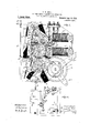
- Figure 1 is a front elevation of a multiple signal-transmitting apparatus embodying this invention, the front plate being removed.
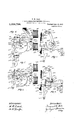
- Fig. 2 is a right-hand side elevation of the apparatus shown in Fig. 1.
- Fig. 16 i s-a diagram of the circuit and devices of a part of an electric signalsystem, involving the employment 0 the signal-transmitting device.
- Fig. 17 is a front elevation of a modified formof s1 nal-transmitting apparatus, the non 'inter ering devices be ing omitted.
- F lg. 18 is a diagram of the circuit-connections of thetransmitter.
- spur-gear represents a spur-gear connected with a barrel m containing a main-spring. Said gearengages a spur-gear m, which engages a pinicn mi, secured to a shaft m", bearing a spur-gcaIn-m, which engages a pinion m, secured to a shaft 11f, bearing a spur-gear m, which engages a pinion m, secured to a shaft m bearlng an escape-wheel m, with which cooperates asuitable pallet.
- a detent m is secured to said shaft m which is normally engaged by an arm m of a lockinglever, which is secured to the pivot-shaft of v the armature-bearing lever m; of the starting-magnet m Said magnet 15 normally rlemiagnetized and its-armature is held in its retracted position by a suitable retractile-" spring m", and the locking-lever m is thereby normally held in engagement with the detent to hold the train at rest.
- a signal-wheel m is secured to the shaft m", to be revolved thereby, and at the edge of said wheel a signal-key m is arranged,
- the electric signaling-circuit including said contactpens is thus oper'ated'to send a signal.
- adisk m f is secured see' particularly Figs. 9 and "i0 which cooperates with an arm, mi", of the locking-lever; It has a two-stepped notch m, at a single point in its periphery, which is made quite long and adapted to receive apin m, extended laterally from said arm m, to'allow the locking-lever to move into locking position and engage the detent m;
- the locking-lever when moved by the starting-magnet to disengage the detent m, is not permitted -to returnand reengage said detent and stop the train by reason of the unnotched portion of the disk moving be.- nea-th the pin m until said disk has-made a complete revolution.
- circuit-closer f is the one which is mornem. tarily closed to cause an on-duty s1gnal,.
- a pawl m is pivotally'motmted see Figs. 4 and 6, the en-' gagingend of which rests on the periphery disk m has a single notch m the radial side of which is arranged to be engaged by the pawl at or just before the end of the first round of the number transmitted,
- the pawl 151" has an extension m which extends to the edge of the disk m or thereabout, and when said pawl enters the notch m in the disk m, its extension moves over the side of the long notch in the disk m and it is during this time that the extension on the pawl is engaged and held by the pin long enough to disengage the pawl from the notch of disk m.
- the pawl m and toothed-disk m constitute a clutch, and, in lieu thereof. a clutch of other suitable form may be employed. It. will be noted that the operation of the clutch is controlled by the starting-magnet. Said clutch is employed for the purpose of connecting the signal-determining devices with the transmittingmechanism.
- the disk m as here shown,
- an emergency disengaging device is provided, see Fig. 11, consisting of a lever m pivoted to the frame,.having a projection which engages the periphery of a disk m, secured to the spur-gear m, and said disk has a raisedpo'rt-ion which will lift the lever m after the transmitter has transmitted five rounds of its code-signal number.
- a cam-disk It Fastened to and mounted on the face of the spurrgearm is a cam-disk It, onwhich restsa pivoted lever h, which is connected by a rod it with a restoringdever it, adapted to engage and move a lever h, to
- This circuit-closer h is one which is automatically closed to cause an off-duty signal when a signal from some watch substation has not been received within a certain reasonable lapse of time.
- the camdisk 713 is so proportioned, and its movement so-controlled, that it will operate to raise the lever it and thereby open the circuit closer [L at or just before two rounds of the identification number have been transmitted.
- the circuitclosers for operating the branch or other circuits connected with the starting-magnet which are employed for the purpose of operating the signal-transmitter to send other signals, vasthree rounds, four rounds, and five rounds, are all designed, when closed, to-remain closed permanently untilmanually or otherwise restored, and hence the armature of the starting-magnet will remain'in attracted position until said circuits are opened.
- additional circuit-closers are represented at a, a. controlled by a relay 0:; and at 0, controlled by a slow-responding electromagnet' t in a. circuit controlled by a circuit-closer t, and at a, a, also controlled by said relay a, see Fig. 16, and
- switches as 1 y, and 7c, are employed for opening the circuits, each comprising a pair ofnormally closed contact-pens adapted to be separated to open the circuits by the o eration of the supervisory signal-transmitter.
- the circuit-closer a a con-arises, as here shown-,s back contact tad armature of a. relay (a reference being had,to my application #555,601, and the armature of said relay normally occupies a semi attracte ed position, and when the circuit of said relay is broken or other trouble occurs whereby thearmature of said relay is caused to" fullyretract, a circuit of the start-ingma'g:
- the circuit-closer t is designed to be operated automatically in the .usual manner by a thermostat'or sprinkler of ordinary construction, reference being had to my application #555,602, and when operated to close the circuit of the electromagnet t, and said electro-magnet t has a slow responding armature which controls the operation of the circuit-closer '0, of a circuit of the starting magnet m including a switch 7', so that said magnet m responds to a prolonged closure of the circuit-closer t, and its armature will remain in 'its attracted position until the circuit of the electro-Inagnet 25 is opened by the switch j.- An automatic fire-signal; is thus sent, being a signal of four-rounds.
- the relay a is also adapted to respond to an auxiliary fire-signal, reference being had to my app ications #555,601 and #555,602,- and its armature being normally in a semi-attracted position is adapted to be moved into attracted position upon the operation of an auxiliary firesignal device, and when so moved will tripthe circuit-closer a, (r of a circuit of the starting-magnet m ncluding a switch In,
- the cam-carrying shaft m is turned for the purpose of movingthe several cams to engage and open the several switches
- cam-disks i, j, and k are arranged to engage their respective switches at different times, as, for instance, when the cam-disk h is moved in response to a signal ofmore than two rounds, as it will be if the armature of the starting-magnet remains in its attracted position, the pin '5 will turn the cam-carrying shaft to first bring the.
- cam-disk i intoengagement with the switch z, to open it, next the cam-disk '1" into en- 'the restoring-sp i as operated and the circuits including them opened, one after the oth'er,'and, when the branch-circuit which is closed by a circuitcloser that was operated to start the transmitter is opened, then the armature of the starting-magnet is free to be retracted and the transmittenstopped at the end of the round during or at the end of which the switch wasopened;
- a disk 5 is secured to the front end by a sprin 2' and a cord i, or other means see Fig. l is connected to said catch-lever for the purpose of moving it to disengau'ge the notched disk.
- a long notch is formed on the signal-wheel m t 25 also engages the'signal-i-key when both the 5 arrives bene'a N lever, and while thejsigna'l-key is raised on but the signal-key. is prevented from falling into said notch whenonly one round is sent and in the following manner:
- a lever -n, pivoted at. n, has aprojeciion at one side which is held pressed into engagementwith a cam-disk n secured to the'side of the signal-wheel m or otherwise arranged to move with the signal-wheel.
- This cam-disk n has a long notch which corresponds to b the long.
- notch betW emrounds on thesignal-wheel, andit passes beneath the pro ection on lever n slightly retarded or out of step with the movement 'of' the longnotch on the signal 'wheel beneath the engaging portion .of the signal-key; but normally both long notches are arranged beneath-the engaging-projections of their cotiperating levers.
- lever n "normally lies in the path of movement of thesignal-key, at which time said key is in raised position, with its circuit-contacts-closed, see'Figs, 1 and 17, said lever being held in such position independentlyof the signal-wheel by a pin n on the lockinglever-arm m which pin lever bearing it'and key are intheir normal positions. 7
- the locking-lever is moved, to disengage the stop-wheel, see Fig. 4', its pin is raised so as to disengage the-signal-key, but
- the signal-key be engaged orsupported by the locking-lever, hence as the long notch of the signal-wheel passes beneath the sig- .nal-key saidgkey will move into said long.
- the multiple transmitter embodying .this invention is also here shown as provided with means wherebyit is absolutely-noninterferin and successive for all its sigthe operation of the startingn'als, so tiat, regardless of how-many of such-transmitters are opera-ted simultanelousl or one after another, on a circuit, no con s on will arise at the CQHtI'IIlSiEItIOH and no'signal will be lost.
- m represents the non-interference magnet which is” included in series with others 1n'the c1rcu1t over Whl0h the signals are transmitted, and m is ts armature, which is'attached'to a lever m pivoted at Inf and bearing the non-interference lever m..
- Severalp ns or pl0]eCt XOIlS extend later m is adapted to coiiperate with the signalkey and also with a latch-lever m, which,
- the lever extends a 'shortdistance below signal-key above the notch therein and exof the pin m by the pin a onthe locking-' ranged opposite each other on the lever m.
- notched portions of said key and lever are arranged so that the lower end ofthe notchthe upper end'of the notch in the key.
- the pm 122 passes its engaging pro ection on latch-lever 4175" to unlock the non-interference lever m at such a tune before the signal-key could first open the circuit that the intervening time would be longer than the length of any closure of the circuit dur ing a signal'and ifthearmature drops away during this time, then the latch-lever will preventit returning until said latch-lever isagain moved by .pin m? 'just before the beginning of another round of the signal wheel, when the non-interference lever is again placed under'the control of the nonintcrfercnce magnet, as at the beginning of the operation.
- the latch-lever As the latch-lever is free to actat all times, except while being lifted by pin m", it can lock out the armature of the non-interference magnet at any time said armature is retracted during signaling, and, as said armature is unlocked and put under control of its signaling-circuit on every clcsn're of its signal-key, it will immediately on ⁇ out its signaling-device at any time that the signal is not being properly sent, as from any accidental or other break, and will' therefore prevent interference even though two or more transmitters had startedsimultanvously, or had sent more or less impulses in unison, as one of the tii-ins'mitters will be cut out the moment .the other opens the circuit out of unison therewith, lemiug the full control of the rircuit to one alone.
- the clutch-pawl 111"" has arranged on it a form-ml extension mi", and the pin in bn the non-inieri'crenw lever In is adapted to be moved by said lever, when said lever is rein-acted under the conditions above-named, or equivalent conditions, into position to be engaged by said extension m"- so that its pawl inwill be moved by such engagement to unclutch the disk and permit the return of the signal-determining devices which are brought into action when the members 5 of the clutch are in engagement.
- a circuit-"controlling device is provided at the transmitter, so that, whenever thecircuit breaks and stays broken-longer than any break which would be causedw by a signal, the circuit-controlling-devicev will be operated and a ground connection established over which the signal will be sent:
- Figs/1, 7 and 8 m represents a contact-pen which is connected with a ground branch circuit. It is attached to alever m pivoted at m", said lever having a bifurcated extension m, which is engagegl by a pin m on anarm m pivoted at m, and to said pivot-shaft a plate in is fixed, having its end formed with a series of steps m, and having on its side two pins m m, arranged a short distance apart, to be has a pin m adapted to be moved into position 'to engage the endof va spring-catch 5 m attached to the locking-lever arm m
- the pin borne by it first engages the pin m and acts to move the plate a short distance, but far enough for the first step thereon to engage the pin er 6n the non-interference, lever m, and inch-engagement will be effected if said nonter'ference lever is in its elevated position,-,
- the non-interference lever isi elevated position when the plate is moved,'as it will b'incase the circuit is continuously broken during or prior to the first revolution of the pinion, the first step of the plate will engage the pin m, and, during the next revolution, the pin m will engage pin m to further move the plate m, and the second steof theplate will engage-said pin m, and, at the same time, the pin at will pass over the end ofthe spring-catch m on the locking-lever, so that the plate will then 3 "second estep, and such additional upward movement of the lever will cause the pin m? to engage the arm m on the pallet and stop the train while in such most upward i position.
- lf 4h1 Cll011itflS scl'ose'd As soon as-the ground connection is thus established, lf 4h1 Cll011itflS scl'ose'd.”
- a signal may be transmitted it either as the.signalii1g-contacts-are'ponnected in circuit between the coils ofthe non-interference magnetfand thereforexmeor the'other 12E- coil will be in either 'groun'd circuitthat may be inade by-the operation ofthe' transmitter.
- m and m represent radial arms on the winding-device of the main spring ofnthe transmitter to which handles or levers may be connected, either of which 'may be operated to wind said spring. 7
- a signal-transmitter having a signalf-wheel and, mechanism 'for operating it to "transmit several different-signals, and a tag.
- a signal-transmitter having a signal- .Nheel for transmitting an identification number, and mechanism for operating itgto transmlt said number one or more times for difierent signals, and a plurality of signal-determining devices operatedby the transmitting-mechanism and adapted to control its operation to determine the number of times said number shall be trans- "mitted, substantially as described.
- a signal-transmitter having .a signalwheel adapted' for transmitting signal-im-v pulses representing a code-identification signal,-and signal-impulses in addition thereto representing other signals, means for operating it to transmit the difi'erent signals,-and a plurality of signal-determining devices operated successively by the transmitting-meChanism and adapted to control its opera-- tion to determine the signal which shall be transmitted, substantially as described.
- a signal-transmitter having a signalwheel and mechanism for operating it to transmit difi'erent signals, a starting-magnet .-for the transmitting-mechanism, and a plureality of signal-determining devices oper;
- a starting-magnet for the signal-sending mechanism connected with two signaling-circuits, each circuit having a circuit-closing device to operate the starting-magnet, and means operated by the signal-sending mechanism to open one of said circuits, substantially as described.
- a signal-transmitter having a signalwheel, and mechanism for operating it to transmit diflerent signals, a starting-magnet for said transmitting-mechanism connected with several circuits, each having a circuit operating device, and means operated by the transmitting-mechanism for opening said circuits, substantially as described.
- a signal-transmitter having a signalwheel and, mechanism for operating itto transmit diflerentsignals a starting-magnet .for said transmitting-mechanism connected with several circuits and adapted to be operated by a circuit-operating device in each circuit, and means operated-by the transmitting-mechanism for openin said circuits at different periods of tlme during the operation thereof, substantially as described.
- a signal-transmitter having a signalwheel, and mechanism for operating it, a starting-magnet for said transmitting-mechanism, connected with a circuit having a circuit operating device, andmeans operatedby the transmitting mechanism for operating the circuit' opera'tingdevice of the circuit n ti'saidstarting-magnet to open the circuit, substantially as described.
- a signal-transmitter having means for sending different signals, a starting-magnet for the signal-sending mechanism connected with a signaling-circuit havingtwo circuitoperating devices, one to close and the other to open said circuit, and means operated by the signal-sending mechanism for operating one of said circuit-operating devices to open the circuit of the starting-magnet, substanj 'tially as described.
- a signal-transmitter having means for sending difierentsignals, a starting-magnet for the signal-sending mechanism connected with two signaling-circuits, each having a j circuit-closing device, and means operated by the signal-sending mechanism for operating one of said circuit-closing open the circuit of said starting-magnet,
- a signal-transmitter having means for sending diiferentsignals, a starting-magnet fonthe signal-sending mechanism connected with several s1gnal1ng-c1rcuits,'each having a circuit-operating device, and means' operi ated by the.signal-sending mechanism for opening one of the circuits of the starting- 'magnet, and 'means operated-by thesignalsending mechanism for operating one of the .circuit-operating devices to open another I evices to circuit of the starting-magnet, substantially as described.- 12.
- a signal-transmitter havinga signalwheel and mechanism for operating 1t, .-a starting-magnet for said transmitting-mechanism, connected with a circuit having a circuit operating device, a cam-disk operated by the transmitting-mechanism, and means operated by said cam-disk. for op'-. erating the circuit-operatingdevicegof; the circuit of'said startin #magnet to o en .the said circuit, substantially as described 13.
- a signal-transmitter having a signalwheel and mechanism for-operating it to transmit different signals, a starting-magnet for said transmitting-mechanism, connected with several circuits, all having circuit-operating devices and some having switches,
- a signal-transmitter having means for sending difierent signals, a start-ingmagnet for said signal-sendingmechanism, a circuit operating-device for the 'circuit'of said startlng-magnet, a signal-determining device operated by the signal-sending mechanism and adapted'to operate said circuit-operating device to op'enthe circuit of the starting-magnet, and means operated by the starting-magnet to disconnect said signaldetermining device from the signal-sending,
- a signal-transmitter having means forsending diiierent sigi ials, a starting-magnet for said signal-sending mechanism connected with severalsignalingwircuits, each having acircuit-operating device and a switch, a. plurality of s1gnal-deterniining devices operated by thesignal-sending mech-' anism to open said switches and thereby con- .trol the operation of the starting-magnet,
- mining device operated by the transmittingmechanism and adapted to control its operation to determine the signal which shall be transmitted, and means for restoring said signal-determining device at the completion of asignal, substantially as described.
- a signal-transmitter having a signalwheel and mechanism for. operating it to transmitdifi'erent signals, ,axsignal-detcrmining device operated by the transmittingmechanism and adapted to control its operation to determinethe signal-which shall be transmitted, and means for restoring said signal-determining device independently ,of the transmittingmechanism'at the completion of a signal, substantially as described.
- a signal-transmitter having aasignalwheel and mechanism for operating it to transmit difieren't signals, a' plurality of signal-determining devices operated successivel by the transmittmg-mechanism and adapted to control its operation to determine the signal which shall be transmitted and restoring means for said signal-determining devices, substantiallyas describe 21.
- a signal transmitter having a signal- .wheel, and mechanism for operating it to i transmit different signals, a startlng-magnet for said. transmitting-mechanism, a signaldetermining device operated by the transmitting-mechanism, adapted to control the operation of the starting-magnet to deter-.
- a signal-transmitter having a signalwheel and mechanism, for operating it to transmit different signals, astartin magnet for said transmitting-mechanism, a signaldetermining device for operating the circuitoperatrng. device of a circuit for said start- 'transmit difi'erent signals, -for the t-ransmitting-mechanisi'n anda Sig-- adapted to be oping-magnet to open the circuit, and restoring means'for said signal-determining device, substantially as described.
- a signal-transmitter having means for sending different signals, a starting-magnet or said slgnal-sendmg mechanism, a c1rcu1toperating device for the circuit of said magnet, 3. signal-determining device operated by the signal-sending mechanism and adapted to operate said circuit operating device to open the circuit of the starting-magnet, and
- a signal-transmitter having means for sending different signals, a starting-magnet for said signal-sending mechanism connected with several circuits, each having a circuitoperating device and a switch, several si g nal-deter1nining devices operated by the signal-sending mechanism to respectively open said switches and thereby control" the operation. of the starting-magnet, and restoring-means for said signal-determiningdevices, substantially as described.
- a signal-transmitter having a signal-- wheel and mechanism for operating it to transmit different signals, a plurality of sig rial-determining devices adapted to besucccssivelyoperated .by mechanism to control its termine the signal which shall be transmitted, and a clutch for connecting said signal uetcrniiningdevice with said transmittingmechanism, substantially as described. 29.
- a signal-transmitter having-a signal wheel and mechanism for i the transmittingnal-determining device operation and deoperating" it to a st-arta'zfgemagnet erated. by" the transmitting-mechanism; to-
- Asig'naLtra-nsmitter having a signal wheel .and mechanism for operating it to transmit signal-impulses representing a code identification-signal and other signal-hm.
- a. starting-magnet for the transmitting-mechanism and 3 a signal-detenminin-g device adapted to be operated by the transmitt-ing-mechanism to control the operation of the startingmagnet to determine the signalwhich shall be transmitted, a clutch for connecting said signal-determining device with the transmitting-mechanism when the identification signal has been sent; andmeans controlled by the starting-magnet for disengaging the clutch when thesignal-impulses of another signal have been sent, substantially'as described.
- a signal-transmitter having a signal- Wheel and mechanism foroperating it to transmit different signals, a starting-magnet d a sigerated by the transmitting-mechanism to determine-thesignal vihich shall be transmit ted, and a clutch for' c'onnecting saidsig- 'nal determining device'wi'th the transmitting-mechanism, the operation of which is said starting-magnet, and means for restoring said'signal-detemniningdevicewhen the clutch is operated to disconsnectit from the transmitting-mechanism,
- a signal-transmitter ha'vinga signalwheel and'mechanism for revolving it to transmit signal-im ulses representing a code identification num er and additional signal-impulses representing other signals, a
- anism a signal-determining-device adapted to be operated by the transmitting-mechanism to open the circuit of the startingmagnet, to thereby determine the signal which. shall be transmitted, a clutch for connecting said signal-determining-device with the transmitting-mechanism and means opthe clutch to disconnect thelsi al-determining-device from the 'transmittingsmechanism at the endpieach grou of si al-impulses, and restoring means or sai signalsubstantially as describedj 33.
- a signal transmitter having a signalwheel and mechanism for revolving it to' transmit different signals, a starting-magnet for the transmitting-mechanism connected with several -circuits, each havinga c ircuit-operating-device, and a plurality of sigerated by the starting-magnet for operating.
- determining-devices j with the transmitting-' mechanism means operated by the starting'- magnet for controlling the operation of said clutchand means for restoring the-signaldetermining-devices when the clutch i erated to disconnect them from the transm-itting-mechanism, substantially. as described.
- a signal-transmitter' havinga 'signal-' wheel and mechanism for revolving it to transmit difi'erentsignaIs, a starting-magnet the endof a signal, a clutch for connecting for said transmittingmechanism connected with a circuit having, a circuit operating-fl device'tand also a switch for openingsaid circuit, a cam for operating said switch' at the cam-shaft bearing said cam.
- the transmitting-mechanism means 'operated the starting-magnet for operating" vsaid clutch -to' disconnect the camshaft from-the mitt-i rig-mechanism,
- a signal-transmitter havin a signalwheel and mechanism for revo trolled bythe -starting-mag iet, and means' for restoring said cam-shaft when the-clutch is operate'dfto disconnect it from'the trans-- substantially as described.
- a signal-transmitter ' having' a signalwheel with a long notch and mechanism for 4 operating it to-transi'nitdifi'er'ent signals, a
- s gnzil key for-holding the signal key from coac'ting with the signal-wheel while the longhnotch of the signal-wheel passes beneath it.o n the first round of the I signal-wheel and thereafter releasing said key, permitting it to engage the signal-wheel during the remainder of the round and 'on s gnal-key,- a'cam-disk movable with thesignal-wheel, a lever engaging said disk for holding the signalrkey from coacting with v I r i .the signal-wheel while the long notch there- 34.
- 'Asignal-transmitter having a signalwheel and mechanism'for operating it to transmit difierent signals, a starting-magnet.
- a signal-transmitter having a signal- .wheel and mechanism for operating t to transmit difierent signals, a signal-determining-device operated bythetransmittingmechanism and adapted to control its operation, to determine the signal which shall be transmitted,-a -clu.tch for connecting said sign a l determining-device wit-h thetransmitting-mechanism, a locln'ng-device for locking the signal-determiningdevice in its abnormal position and means-for restor ng said signal determiningdevice when released,
- a signal-transmitter having a signah wheel and mechanism for operating it to transmit difi'erent signals, astarting-rhagnet connected with several-circuits havin circuitoperating-devices 'and- :normally- :closedswitches, means' operated by the transmitting-mechanism; for successively opening saidswitches at the ends of the difi'erent: signals, a clutchfor connecting said switch 4 opening means with the transmit-ting-mechanism 1 controlled by the starting-magnet, whereby said switch-opening means is disconnected from the transmittingmechanism at the completion of .the signal, and alo'cklug-device for said switch opening-means'for holding .it'in'its abnormal position, and a means, substantially as described.
- a signal-transmitter having a signalwheel and mechamsm for operating it to transmit difi'erent signals, a starting-magnet them, a clutch for connecting said cam-shaft with-the transmitting-mechanism cpntl'ollerl by the st-arting-magnet,'a locking-device forrestoring-device for 'said switch-opening and means for restoring said cam-shaft whenrelcased, substantially as described.
- a noninterference signal-transmitter having means for sending several difi'erent signals and having selecting means to operate it to send the difierent signals, and a noninterference device controlled by the signalsending mechanism and the transmitting circuit over which the signal is sent, to contr ol the operation of the signal-sending mechanism, substantially as described;
- a non-interference signal-transmitter having means for 'se1di,.g.several difierent signals and having scle vting means to oper-. ate it to send the different signals, and a non-interference device controlled by the signal-sending mechanism and the transmitting circuit over which the signal is sent, to control the operation of the'signal-sending mechanism,'and also to' keep the signalsending. mechanism set when once operated stantially as described.
- a non-interference sign havin 'si nal-sendin mechanism res onsive to the operation of the signaling-circuit, a signal-determining device operated by the signal-sending;mechanism to open said signaling-circuit when the signal has been sent, a non-interference device controlled b the signal-sendin mechanism and by the circuit .overwhich't e signal is sent to control the ;operat10n of the signal-sending. mechanism and the'si mil-determining device operated thereby,-su stanti'ally asidscrib'ed.
- a non-interference signal-transmitter having a signal-wheel for sending an identification number, and mechanism" for oper ating it to send said number, one or more times for different signals, 1 plurality of signal-determining devices operated by the signal-sending mechanism and adapted to control its operation to determine the number'of times said number shall 'be sent, a non-interference device controlled by the signal-sending mechanism and circuit over which the signal is sent, to control the op'er ation of the signal-sending mechanism and I signal-determining devices operated there by, substantially asdescribed.
- a non-interference signal-transmitter comprising Signalsending, mechanism, a startingmagnet therefor, responsive to the operation of a signaling-circuit, a non interference device including-a magnet,-which is controlled by the signal-sending mechanism and the transmitting-circuit over which the signal is sent to control the operation" of the:
- a non-interference signal-transmitter comprising signal-sending mechanism adapted to send several different signals, a starting-magnet therefor, responsive to the operation of several signaling-circuits, a non-interference device including a met, which a is controlled by the signal-sending meclfa nism, and the transmitting-circuit over which the slgnal issent to control the operation'of the signal-sending mechanism and;
- a non-interference sighal-transriiitteif comprising signaLsending mechanism adapt
- A- non-interference signal-transmitter comprising signal-sending mechanism adapted to send several different signals, a starting-magnet therefor, responsive to the operation of several signaling circuits, a plurality of signal-determining devices operated by, the signal-sending mechanism adapted to control the operation of the-starting-magnet to-determine the signal vvhich shall be transmitted, a noneinterference' device including a magnet, which is controlled by the signalsending mechanism and transmit-ting-circuit over which the signal is sent, to control the operation of the signal-sending mechanism and also the signal-determining devices, substantially asfiescribed.
- a signal-transmitter comprising'signalsending mechanism'adaptd to send over a trans'mittingcircuit several different signals, a starting-magnet for said signal sending Inechanismconnected with several signailing-circuits, each having a circu-it-operat, mg device, means operated by "the s1gnal-.
- a signal-transmitter comprising sigr al-sending mechanismadaptedto send over' a transmitting-circuit s'everal' difierent signals, a starting-magnet for said signal-sends ing mechanism connected with several sig naling-circuits, each having a circuit operating device, means, operated “by the signalsending mechanism for opening said signaling-circuits at difierent'periodsiof time to controlthe operation; thereof, a magnet, re- --sponsive,eto .the operation ofthe transmitting-circuit, and .means controlled by [said magnet-for. controlling the operation of saidmeans, substantially 1 as described.-
- a signal-transmitter comprising sig nal-send iri'ggnechanlsm. adapted to. send a signal over a transmitting-circult, atstartingmagnet for saidsignal s endi ngmechanism connected with a signaherrcmthavmg a"circhit-operating device, means operated by, the signaLs'endingmechanism for operating said circuitroperating devicetoopen the ircuit,
- a signal-transmitter comprising signal-sending mechanism adapted to send different signals over a transmitting-circuit, a. starting-magnet for said signal-sending mechanism connected with several signalingcircuits, all having circuit-operating devices and some having switches, means operated by the signal-sending mechanism for operat-' ing the switches at different periods of time I to open the signaling-circuitsand thereby control the operation of the signal-sending mechanism and the signal sent by it, a mag net'responsive to the operation of the transmitting-circuit, and means controlled by said magnet for controlling the operation of said switch-operating means, substantially as described.
- a signal-transmitter comprising signal-sending mechanism adapted to send sev- "'eral difi'erent signals over a transmittingcircuit, a starting-magnet for said signal:
- a signal transmitter comprising sige nal sendlng mechanism adaptedto .send
- a signal-transmitter comprising signal-sending mechanism adapted to send several different signals over a transmit-tingcircuit, a plurality of signal-determining devices operated successively by the signalsending mechanism 'and adapted to control its operation to determine the signals which shall be sent, a magnet responsive to the operation of the transmitting-circuit, and
- a signal-transmitter comprising sig-' ting-circuit, and means cont-rolled by said magnetto control theoperation ofsaid signal-determining device, and restoring-meansfor said signal-determining device, substantially as described, v
- a signal-transmitter comprising sig naI-sending mechanism adapted to send several different signals over a transmitting- -circuit, astarting-magnet for said signal sending mechanism connected Wlt-h SC VlL-BIal signaling-circuits, each having a circuit-o1 erating device and a switch, a plurality of signal-determining devices operated by the signal-sending mechanism to open said switch'sand thereby control thevoperation of the starting-magnet, a'magnetresponsive to the operation of the transmitting-circuit, and means controlled by said magnetfor cont-rolting the operation of said signal-determining devices, and restoring-means for ,said signal-determining devices, substantially as described;
- A- signal-transmitter comprising signal-sending mechanism adapted to send several diti'erent signals over a transmittingcircuit,'a starting-magnet for said signalsending mechanism connected with several signaling-circuits, each having a circuit-operating device and a switch, a plurality of signal-determining devices operated by the signal-sending mechanism to open said switches'and thereby control the operation of the starting-magnet, a niagnet'respoi'i'sive to the operation of the transmitting-circuit, and means controlled by said magnet for controlling the operation of said signal-determining deviees,'and manually operated restoring-means for said signal-determining devices, substantially as described.
- a non-interference signal-transmitter 'stantially as described.
- non-interference magnet-and means coninterference-magnet and means controlled by said magnet for operatingsaid clutch to disconnect said .signal-determining-device. from the transmitting-med]anism, and re-- storing, means for said -s1g'nal-deternm ungdevice, whe'rebyit maybe restored preparatory to being again engaged at the beginning of a subsequent identification number, substantially as described.
- a nonfinterference signal-transmitter having a signal-wheel for transmitting an identification number, and mechanism for operating it to transmit said number one or more times for difierentsignals.
- a non-interference signal-transmitter having a signal-wheel for transmitting an identification number,- and mechanism for
Landscapes
- Business, Economics & Management (AREA)
- Emergency Management (AREA)
- Physics & Mathematics (AREA)
- General Physics & Mathematics (AREA)
- Lock And Its Accessories (AREA)
Description
. P. W. COLE ELECTRIC SIGNAL TRANSMITTING APPARATUS.
I APPLICATION TILED APR. 15, 1910. 58,728. Patented Apr. 15,1913.
ll iziias'sesg J ZZ cVZZOII WWW. M
F. W. COLE. ELECTRIC SIGNAL TRANSMITTING APPARATUS.
APPLIOATION FILED APR.15, 1910.
Patented Apr.15, 1913.
( SHETITS SHEET 2.
,1". W. COLE.
ELECTRIC SIGNAL TRANSMITTING APPARATUS. APPLIOATION FILED 111 11.15, 1910.
1,058,728. Patnted Apr. 15, 1913.
6 SHEETS-SHEET 3.
' fl ygn M'Znases 'Jizmgzzior;
F. w. 00m.
ELECTRIC SIGNAL TRANSMITTING APPARATUS.
APPLICATION FILED APR.15, 1910, 1,058,728. Patented Apr. 15, 1913.
6 SHEETS-SHEET 4,
ll/ti flasnsas'p v 4 Jim/6727074: H ab aha MM 7% H 1 JL I I r '%)M44-46'M/ asses: Hflbw. &
P. W. COLE. ELECTRIC STGNAL TRANSMITTING APPARATUS.
Patented Apr. 15, 1913.
APPLICATION FILED APR.15', 1910.
fins 72%? JLM 72 M P. W. COLE. I ELECTRIC SIGNAL TRANSMITTING APPARATUS.
APPLICATION FILED APR. 15, 1910.
Patented Apr. 15, 1913.
6 SHEETS-SHEET 6.
jfiuezzlor;
UNITED STATES PATENT OFFICE.
FREDERICK W. COLE, OF NEWTON, MASSACHUSETTS, ASSIGNOR TO THE GAMEWELL FIRE ALARM TELEGRAPH COMPANY, OF NEW YORK, N. Y., A CORPORATION OF I NEW YORK.
ELECTRIC SIGNAL-TRANSMITTING APPARATUS.
Application filed April 1-5, 1910. Serial No. 555,605.
To all whom it may concern Be it known that I, Fnnonmoii \V. Cons, of Newton, in the county of Middlesex and State of Massachusetts, have invented an 5 Improvement in Electric Signal-Transmitting Apparatus, of which the following 1s a specification.
This invention relates to electric signaltransmitting devices, and has for its ObJGCt the construction of an improved form of multiple signal-transmitting device adapted to send a number of differentsignals,
preferably with a differentiating signal impulse in connection with some of the sigmils, whereby'the signals may be received upon an electric signal-recorder of any usual or suitable construction, and those signals having a-diiferentiating signal-impulse may cause the operation of 'an'audible alarm,
y This signal-transmitting device is especially adapted to be..nse d in connection with supervisory signal-systems, such as represented in my applications for Letters Patents, Serial Numbers 555,601, 555,602, 555,603 and'555,6 0 -1. I
My invention is embodied in an apparatus adapted to send a code-signal wh ch preferably represents a number to identify its location. The identification number once 0 sent may be termed a round. The different signals are represented by the number of times this identification number is; repeated; as, for instance, the identification number once sent, or one round, will constitute a certain signal; twicesent, or two rounds, another signal; and so on: Each round may be composed of a series of signal-impulses of short duration, and between all, or at least some of the rounds, a prolonged sig- 0 nal -impulse may be employed asthe difi'erentiatingsignal-impulse. In such case the signals on the tape of a recorder w 1ll be represented dots, and the differentiating signal-impulses by dashes.
.The signal transmitting-apparatus embodyingmy invention comprehends the employment of a starting-magnet by Wli1Cl1 1t is release dfoi' caused to operate, and said magnet is connected in an electric circuit '50 which hasseveral branches, each having one or more circuit-closers, foroperating the starting-magnet according t0-the dlflferentsignals to be-sent; yet the apparatus may be otherwise operated. As the different signals are represented by a different number of rounds, the operation of the transmitter, when released to send any of them. will be governed according to the number of rounds to be transmitted by it. and, for this pur- :pose, signal-determining devices are emplayed, adapted-to be operated by the transmitting mechanism in conjmiction or coiip- ?eration with the means operated to release 5 it, to determine the number of rounds which ;shall be transmitted in response to the pari ticular releasing-means operated.
For simplicity of construction the starting-magnet maybe employed to serve also @as the controlling-magnet for the trans- Emitting mechanism-and, in such case, the
imagnet, or the branch-circuits for said circuit-closers will be respectively controlled Eby the signaldetermining devices; as, for finstauce, the circuit-closer in one branch of the circuit of the starting-magnet may be operated momentarily and be self-restoring, rand, in such case, the starting-magnet will be momentarily operated, and therefore will gmerely release or otherwise operate the 'transmitter to send a signal 'of one round; ;the circuit-closer of another branch may be operated permanently and a signal-determining device provided for opening it or restoring it to normal when a signal'of two rounds has been sent by said transmitter; :the cir cuit-pioser's of other branches of the lcircuit may be operated permanently and signal-dete'rmining devices employed for =opening these branches of the circuit when four or five rounds.
Both forms of signal-determining devices for. thus mechanically and also electrically controlling the operation or the effect of the operation of the circuit-closers are herein adopted, and they may. and preferably will .be operated by the transmitting mechanism. In the circuit of the transmitter over which the code-signals are sent, and which may be operation of suitable non-interfering 'devices connected with the signal-transmitting imechanism, whereby the signal-transmitting mechanism is both non-interfering and successive, and the correct positive transmission of any signal selectedis absolutely insured. The signal-transmitting mechanism also 'the' transmitter-has sent a signal of three or' called a supervLsory-circuit, a non-interfen' ence magnet is provided for governing the has connected with it automatic means-for,
Patented Apr. 15, 1913.
;circuit-closers for operating the startingconnecting a ground-circuit thereto, under certain condltions, or after a predetermined per od of time, so that the signal may be transmitted over a ground-circuit in casethe metallic circuit is out of order. The ground circuit will be connected to the transmittercircuit bet-ween the coils of the non-interference magnet, so that a coil of said magnet will be in circuitin either direction from said ground circuit,'and said ground circuit will be opened and closed simultaneously with the opening and closing of the signaling-contacts which will be connected in circuit between said coils, and a signal sent over the ground-circuit in either direction will therefore be non-interfering and successive, the same as though the ground-circuit was not used.
Means are provided for temporarily stopping the transmitting-mechanism to prevent it from running unnecessarily while attempts ing to send a signal over a disabled circuit.
Figure 1 is a front elevation of a multiple signal-transmitting apparatus embodying this invention, the front plate being removed. Fig. 2 is a right-hand side elevation of the apparatus shown in Fig. 1. Fig.
isan under side view. Figs. 4 to 15, inclusive, are details to be referred to. Fig. 16 i s-a diagram of the circuit and devices of a part of an electric signalsystem, involving the employment 0 the signal-transmitting device. Fig. 17 is a front elevation of a modified formof s1 nal-transmitting apparatus, the non 'inter ering devices be ing omitted. F lg. 18 is a diagram of the circuit-connections of thetransmitter. In the embodiment of my-invention, as
here shown, for purposes of illustration, 111.
represents a spur-gear connected with a barrel m containing a main-spring. Said gearengages a spur-gear m, which engages a pinicn mi, secured to a shaft m", bearing a spur-gcaIn-m, which engages a pinion m, secured to a shaft 11f, bearing a spur-gear m, which engages a pinion m, secured to a shaft m bearlng an escape-wheel m, with which cooperates asuitable pallet. A detent m is secured to said shaft m which is normally engaged by an arm m of a lockinglever, which is secured to the pivot-shaft of v the armature-bearing lever m; of the starting-magnet m Said magnet 15 normally rlemiagnetized and its-armature is held in its retracted position by a suitable retractile-" spring m", and the locking-lever m is thereby normally held in engagement with the detent to hold the train at rest.
A signal-wheel m is secured to the shaft m", to be revolved thereby, and at the edge of said wheel a signal-key m is arranged,
which is mounted loosely on a pivot-stud n. Said key an insulating pin projectmg from it, which engages one member of a pair of contact pens m, ,'m arranged on an insulating-block m, and normally holds V 1 number and a blank space, and on each complete revolution it is designed to transmit said number; but it may be otherwise constructed. When the signal-key is permitted to co-act with the signal-wheel, it engages the signal-wheel and its movements are controlled thereby, being moved in one direction by the spring-acting contact-pen m, to
permit separation of the contact-pens, when entering one of the notches 'of said wheel,
and being moved in the opposite direction to'clcse-the contact-pens when the unnotched portion of the wheel passes by it. .The electric signaling-circuit including said contactpens is thus oper'ated'to send a signal.
To the signal-wheel shaft m, adisk m f is secured see' particularly Figs. 9 and "i0 which cooperates with an arm, mi", of the locking-lever; It has a two-stepped notch m, at a single point in its periphery, which is made quite long and adapted to receive apin m, extended laterally from said arm m, to'allow the locking-lever to move into locking position and engage the detent m; The locking-lever, when moved by the starting-magnet to disengage the detent m, is not permitted -to returnand reengage said detent and stop the train by reason of the unnotched portion of the disk moving be.- nea-th the pin m until said disk has-made a complete revolution. If the starting-magnetis operated only momentarily,as by a momentary closure of its circuit, as, for instance, bythe operation of a circuit-closer the train will be released and'the locking lever will be held in abnormal position by the disk until the notch m arrives in posit-ion beneath the pin m, when said pin will enter said notch and the locking-lever will resume its normal position and engage the detent m and thereby stop the train, and a signal of one round of the identifica tion number only will be transmitted. The
circuit-closer f is the one which is mornem. tarily closed to cause an on-duty s1gnal,.
as for instance, a signal of one-round to be sent, as shown in my application #555,603.
On one side of the disk m a pawl m is pivotally'motmted see Figs. 4 and 6, the en-' gagingend of which rests on the periphery disk m has a single notch m the radial side of which is arranged to be engaged by the pawl at or just before the end of the first round of the number transmitted,
see Fig: 9, so that in case the disk m is caused or permitted to turn more than one will operate to turn the disk m.
ioo
of another disk m, see dotted lines Fig.1, a mounted loosely on the shaft m, and said- The pawl 151" has an extension m which extends to the edge of the disk m or thereabout, and when said pawl enters the notch m in the disk m, its extension moves over the side of the long notch in the disk m and it is during this time that the extension on the pawl is engaged and held by the pin long enough to disengage the pawl from the notch of disk m. The pawl m and toothed-disk m constitute a clutch, and, in lieu thereof. a clutch of other suitable form may be employed. It. will be noted that the operation of the clutch is controlled by the starting-magnet. Said clutch is employed for the purpose of connecting the signal-determining devices with the transmittingmechanism. The disk m, as here shown,
is fastened to a pinion m, mounted loosely on the shaft m, which engages a spur-gear m secured to a sleeve m 'mounted loosely on shaft m.
As soon as the pawl disengages the disk, said disk and parts connected therewith and operated by it, are immediately restored or returned to normal position by a spring m connected at its outer end to the frame and at its inner end with the sleeve m. The
stop for limiting the return movement ofsaid parts is here shown as a pin m projecting from the side of the spur-gear m,
which engages a stop-arm m, fastened to the frame. In order to insure disengagement of the clutch after the transmitterhas operated long enough to send any possible signal, an emergency disengaging device is provided, see Fig. 11, consisting of a lever m pivoted to the frame,.having a projection which engages the periphery of a disk m, secured to the spur-gear m, and said disk has a raisedpo'rt-ion which will lift the lever m after the transmitter has transmitted five rounds of its code-signal number. The end of this lever m, when thus raised, will lie in the path of the, extension at of the pawl m thereby causing said pawl to disengage the disk m, allowing it to be restored in case for any reason it had not been previously disengaged at the end of five rounds ofthe signal-wheel.
Fastened to and mounted on the face of the spurrgearm is a cam-disk It, onwhich restsa pivoted lever h, which is connected by a rod it with a restoringdever it, adapted to engage and move a lever h, to
open a circuit-closer it, see Figs. 1, 15, and 17. This circuit-closer h is one which is automatically closed to cause an off-duty signal when a signal from some watch substation has not been received within a certain reasonable lapse of time. The camdisk 713 is so proportioned, and its movement so-controlled, that it will operate to raise the lever it and thereby open the circuit closer [L at or just before two rounds of the identification number have been transmitted. If the circuit of the starting-magnet is operated, as a result of the action of the circuit-closer 72, its armature will therefore remain in attracted position until said circuit-closer is thus opened mechanically by a rising movement of the lever and, upon the circuit being thus-opened, said armature is thereafter free to retractwhen the pin m of the locking-lever is next oppositethe-notch in the disk m and the codesignal sent will have included two rounds of the identification number. The cam-disk it" and means operated by it thus serve as and constitute one of the signal-determining devices, although its construction may-be modified in many ways.
I The circuitclosers for operating the branch or other circuits connected with the starting-magnet, which are employed for the purpose of operating the signal-transmitter to send other signals, vasthree rounds, four rounds, and five rounds, are all designed, when closed, to-remain closed permanently untilmanually or otherwise restored, and hence the armature of the starting-magnet will remain'in attracted position until said circuits are opened. As here shown such additional circuit-closers are represented at a, a. controlled by a relay 0:; and at 0, controlled by a slow-responding electromagnet' t in a. circuit controlled by a circuit-closer t, and at a, a, also controlled by said relay a, see Fig. 16, and
switches, as 1 y, and 7c, are employed for opening the circuits, each comprising a pair ofnormally closed contact-pens adapted to be separated to open the circuits by the o eration of the supervisory signal-transmitter. The circuit-closer a, a con-arises, as here shown-,s back contact tad armature of a. relay (a reference being had,to my application #555,601, and the armature of said relay normally occupies a semi attracte ed position, and when the circuit of said relay is broken or other trouble occurs whereby thearmature of said relay is caused to" fullyretract, a circuit of the start-ingma'g:
' net m ,-including the switch 2' will be closed,
and atrouble-signal transmitted which-is here represented, as a three-round signal. Said circuitwill remain closed until opened by the switch 2'. The circuit-closer t is designed to be operated automatically in the .usual manner by a thermostat'or sprinkler of ordinary construction, reference being had to my application #555,602, and when operated to close the circuit of the electromagnet t, and said electro-magnet t has a slow responding armature which controls the operation of the circuit-closer '0, of a circuit of the starting magnet m including a switch 7', so that said magnet m responds to a prolonged closure of the circuit-closer t, and its armature will remain in 'its attracted position until the circuit of the electro-Inagnet 25 is opened by the switch j.- An automatic fire-signal; is thus sent, being a signal of four-rounds. The relay a is also adapted to respond to an auxiliary fire-signal, reference being had to my app ications #555,601 and #555,602,- and its armature being normally in a semi-attracted position is adapted to be moved into attracted position upon the operation of an auxiliary firesignal device, and when so moved will tripthe circuit-closer a, (r of a circuit of the starting-magnet m ncluding a switch In,
and when closed will cause said magnet to respond, and the armature of sald magnet will remain attracted until the circuit in-.
with means operated. in conjunction with them serve as and constitute signaLdetermining devices by which the signal 'to be transmitted may be determined, yet my invention includes other forms of signaLdetermining devices arranged to be operated by the transmitting-mechanisin bywhich substantially the same results may be accomplished.
The cam-carrying shaft m is turned for the purpose of movingthe several cams to engage and open the several switches,
through the medium of a pin i see Fig. 13, which projects laterally from the cam-disk h, and engages a projection i on the edge of a disk 2', which is secured to said shaft m. The movement imparted to this camshaft may be more or less, according to the number of rounds, of the signal to be transmitted, and the cam-disks i, j, and k are arranged to engage their respective switches at different times, as, for instance, when the cam-disk h is moved in response to a signal ofmore than two rounds, as it will be if the armature of the starting-magnet remains in its attracted position, the pin '5 will turn the cam-carrying shaft to first bring the. cam-disk i intoengagement with the switch z, to open it, next the cam-disk '1" into en- 'the restoring-sp i as operated and the circuits including them opened, one after the oth'er,'and, when the branch-circuit which is closed by a circuitcloser that was operated to start the transmitter is opened, then the armature of the starting-magnet is free to be retracted and the transmittenstopped at the end of the round during or at the end of which the switch wasopened; 1
When the pawl m already described,
diseng'ages the disk m, said disk and pinion 30 on which it is mounted, and the spur-gearwheel m meshing with it, together with the cam-disk 71, mounted on said gearwheel, will be returned to normal position scribed, and the parts will be stoppedtby the aft 'esaidstop-pin m on thespur-gear en-' gaging the stop-arm m When a signal has been sent, as a result before-de- 35 of the operation of a circuit-closer which remains permanently closed until manually restored, it is obvious that the starting-magnet should not be placed again under the control of such circuit-closer until the latter has been properly restored. It is desirable, therefore, when such signals are sent, that the return movement of the camshaft m shall be manually controlled, so
that the switches which are opened by the cams shall not be closed again until after or simultaneously with the restoration of said circuit-closers. To accomplish this result, a disk 5 is secured to the front end by a sprin 2' and a cord i, or other means see Fig. l is connected to said catch-lever for the purpose of moving it to disengau'ge the notched disk. Thus, whenever any one of the three switches is operated to control the transmission of a three or four or fiveround signal, as the case may be, said switch, in particular, will be held open until it 'is permitted to return by a movement of the catch-lever,
In order thata differentiating signal-im- "pulsemay be transmitted with all the signals,-except the ,one-round signal, a long notch is formed on the signal-wheel m t 25 also engages the'signal-i-key when both the 5 arrives bene'a N lever, and while thejsigna'l-key is raised on but the signal-key. is prevented from falling into said notch whenonly one round is sent and in the following manner: A lever -n, pivoted at. n, has aprojeciion at one side which is held pressed into engagementwith a cam-disk n secured to the'side of the signal-wheel m or otherwise arranged to move with the signal-wheel. This cam-disk n has a long notch which corresponds to b the long. notch betW emrounds on thesignal-wheel, andit passes beneath the pro ection on lever n slightly retarded or out of step with the movement 'of' the longnotch on the signal 'wheel beneath the engaging portion .of the signal-key; but normally both long notches are arranged beneath-the engaging-projections of their cotiperating levers. The end of lever n "normally lies in the path of movement of thesignal-key, at which time said key is in raised position, with its circuit-contacts-closed, see'Figs, 1 and 17, said lever being held in such position independentlyof the signal-wheel by a pin n on the lockinglever-arm m which pin lever bearing it'and key are intheir normal positions. 7 When the locking-lever is moved, to disengage the stop-wheel, see Fig. 4', its pin is raised so as to disengage the-signal-key, but
the leve'r n will remain beneath said signalkey while the cam-disk a revolves with the signal-wheel until 'theraised 'port ion of thecam-disk arrives injposition toylift' said lever, see Fig; 9,- and this 'occurs'just after the end of the long notch on the signal wheel." The signal-keyis th'ns held mechanically. from co-acting with the signal- I wheel orlopening its' circuit-contacts iun'til signal-keytandon 'the first round of, the
to transmit thefdifierentiating. signal-int -'A t the end of the first round of the signah-it' the' starting-magnet 'is-"deenergized, its armature will retract when the first: step .o'f'the'two-ste ped notch in the stop wheel the pin my on the lockingthe last tooth of thegsignal' wheela Such ;movementfof the;1ocking- 1ever is sufficient" to cause the in n to pass beneaththe end [of thesignal', ey and lock it' from dropping into the deep notch, but not suflicient for .the-lbcking-lever .m to be engaged by the detent m", When,-J-.ho'wever, the pin m falls o'n tol'the second, step of the notch in no the stop-wheel, then the; lever m is moved far enough to be engaged by the detent to -s'top the mechanism. The parts are so arranged that the cam-disk n arrive-sin po sition to permit. the lever n to fall and re- 55 sume its normal positipn, only after the last tooth' of the signal-wheel has passed beneath its key. If, however, the armature of the starting-magnet should remain in its 'attrae ted osition at the end of the first round, th 'mec anism will not then be stopped, nor
.wi l the signal-key be engaged orsupported by the locking-lever, hence as the long notch of the signal-wheel passes beneath the sig- .nal-key saidgkey will move into said long.
notch and 0 en itscircnit-conta'cts, so that, during the rst art of the second revolution of the signa -wheel, the circuit-contacts will beuopened'to' cause a long or diiferentiating impulse between the first and second rounds of the transmitter number. The cam-disk a would have permitted thelever n to resume its normal position during this time, but said l'v er, when falling, engages the end of the signal-key, see Fig. 10, and is thereby held, and when the signal-key is again moved by the signal-wheel-to re lease said lever, the signal-Wheel will have been. moved to the end of the long notch,
and the cam-disk a correspondingly moved, so, that said lever will be engaged by the high part of said cam-diskwhile the signalkey rests on the top ofthe first. tooth of the signal-wheel and before the first break of -.tion,o fthe signal to be transmitted, is controlled by magnet .of the said transmitter.
The multiple transmitter embodying .this invention is also here shown as provided with means wherebyit is absolutely-noninterferin and successive for all its sigthe operation of the startingn'als, so tiat, regardless of how-many of such-transmitters are opera-ted simultanelousl or one after another, on a circuit, no con s on will arise at the CQHtI'IIlSiEItIOH and no'signal will be lost.
"m" represents the non-interference magnet which is" included in series with others 1n'the c1rcu1t over Whl0h the signals are transmitted, and m is ts armature, which is'attached'to a lever m pivoted at Inf and bearing the non-interference lever m.. Severalp ns or pl0]eCt XOIlS extend later m is adapted to coiiperate with the signalkey and also with a latch-lever m, which,
ally from said lever 172, one of which. as
for convenience, is pivotally supported on the pivot-shaft-m see Figs. '1 and 4 to 8: anot ier project-ion, as m, is adapted to cooperute with an arm an on the pallet pf- G i p j 1,058,728
1n the lever extends a 'shortdistance below signal-key above the notch therein and exof the pin m by the pin a onthe locking-' ranged opposite each other on the lever m.
inoved down to a position belowthe notch .terferenee-magnet in its attracted position tracted and the lever m controlled by it the train; another, as m, see Fig, 21s adapted to cooperate with the clutch-member m, and another, as m, is adapted to coiiperate With the member controlling the application and removal of a ground-circuit connection. Said pins m and m are ar- The pivoted latch-lever m is arranged in upright position at the side of the signalkey, and the pin m is made long enough to extend over both said lever and key. This latch-lever has a notch in, in its edge, and
notched portions of said key and lever are arranged so that the lower end ofthe notchthe upper end'of the notch in the key.
When the transmitter is at: rest the armad tureof the non-interference magnet is re 'f tracted, see Fig; l, as its'magnetis shunted from. the circuit of the shunt contacts m, and said pin. m lies in the path'of the" tends across the notch in the latch-'lever,-but at such time said latch-lever is held clear lever, which is made long enough to; extend over bothsaid lever and the signal-key.
When the locking-lever is moved to release the train the shunt m is first op'enedby it so that the armature of the non-interference magnet is immediately attracted, but the pin m1? will be caught-by the shoulder on the latch-lever and held until-said lever is raised by pin mi on the signal-wheel a moment after. whereupon the armature will be further attracted until the pin-.m is
in said latch lever,-see Fig; 4. When the train is released the pin n on the lockinglever is moved up above both the lever m and the signal-key, and said key is then heldby the pivoted-lever n, until said lever n is raised to disengage the signal-key after the long notch in the signal-wheel has passed. Vhen the first tooth of the signal-wheel. has also passed beneath the signal-key, ,then said key is free to move toward the .signalwheel, see Fig. 5,'and the upper end "oi: the notched portion thereof will more m'c'r the pinmflto thereby lock the nmr-inicrfercnce' lever m with the armature of the non-inand-hold it while the circuit is opened by the key.
, Should the circuit be in use, as by the sending of a signal from another transmitter at the time this transmitter is started, or should the signaling-circuit be opened duh ing the long interval of time 'prceedingthe L sending of the first signal-impulse of tin round, then the armature of the non-interference magnet will be or will remain reraised, so that the pin at will be opposite to or enter the notch in the latch lever m, andsaid pin m will also overlie the signalkey at a point above the notchin said key, to thereby hold the signal-key from .co-act-. ing with the signal-wheel. 'If the armature is in this retracted position, after the pin 'm has passed its cooperating projection in on the latch-lever m, then the notch in said latch lever will lock the lever m from moving into its most attracted-position to allow the signal-key to thereafter efi'ectively cooperate, with the signal-wheel until said latch-lever is again raised by the pin m upon another revolution of the signal-wheel,
and no signal will be sent meanwhile by reason of the signal-key being positively and mechanically held from opening the circuit uring such revolution. In order, thereore, to prevent a possibility of interference if the transmitter'is started while another signal is being sent, its non-interference devices areplaced under. the control of the circuit before thetransmitter opens the circuit and for a time longer than any closures during signals. To accomplish this result the pm 122," passes its engaging pro ection on latch-lever 4175" to unlock the non-interference lever m at such a tune before the signal-key could first open the circuit that the intervening time would be longer than the length of any closure of the circuit dur ing a signal'and ifthearmature drops away during this time, then the latch-lever will preventit returning until said latch-lever isagain moved by .pin m? 'just before the beginning of another round of the signal wheel, when the non-interference lever is again placed under'the control of the nonintcrfercnce magnet, as at the beginning of the operation. As the latch-lever is free to actat all times, except while being lifted by pin m", it can lock out the armature of the non-interference magnet at any time said armature is retracted during signaling, and, as said armature is unlocked and put under control of its signaling-circuit on every clcsn're of its signal-key, it will immediately on} out its signaling-device at any time that the signal is not being properly sent, as from any accidental or other break, and will' therefore prevent interference even though two or more transmitters had startedsimultanvously, or had sent more or less impulses in unison, as one of the tii-ins'mitters will be cut out the moment .the other opens the circuit out of unison therewith, lemiug the full control of the rircuit to one alone.
The clutch-pawl 111"" has arranged on it a form-ml extension mi", and the pin in bn the non-inieri'crenw lever In is adapted to be moved by said lever, when said lever is rein-acted under the conditions above-named, or equivalent conditions, into position to be engaged by said extension m"- so that its pawl inwill be moved by such engagement to unclutch the disk and permit the return of the signal-determining devices which are brought into action when the members 5 of the clutch are in engagement.
When the transmission of the signal is not interfered with, the non-interference lever remains attracted and said extension 111- passes over and free from engagement with the pin m". By providing this pin m and arranging it to engage the clutchmember and disengage the clutch in-this way provision is made for restoring parts of the transmitter to normal at the end of any signal, and for the re-setting of parts in case the signal is interfered with when but partiallytransmitted, as, for instance, when two rounds of a three, four, or fiveround signal have been transmitted, and, when the parts are reset, the operation will be repeated until the complete signal is sent for which the transmitter wasstarted. It will thus be observed that the clutch is controlled not only by the non-interference magnet for the purpose of disengaging" it when the signal is not properly sent, butalso by the starting-magnet to disengage it when the proper number of rounds have been correctly sent.
For the purpose of applying a ground connection when. the transmitter is operated upon-a continuously broken circuit, so that the signal may-be sent over aground cir: cuit, a circuit-"controlling device is provided at the transmitter, so that, whenever thecircuit breaks and stays broken-longer than any break which would be causedw by a signal, the circuit-controlling-devicev will be operated and a ground connection established over which the signal will be sent:
Referring to Figs/1, 7 and 8 m represents a contact-pen which is connected with a ground branch circuit. It is attached to alever m pivoted at m", said lever having a bifurcated extension m, which is engagegl by a pin m on anarm m pivoted at m, and to said pivot-shaft a plate in is fixed, having its end formed with a series of steps m, and having on its side two pins m m, arranged a short distance apart, to be has a pin m adapted to be moved into position 'to engage the endof va spring-catch 5 m attached to the locking-lever arm m As the pinion m rerolves, the pin borne by it first engages the pin m and acts to move the plate a short distance, but far enough for the first step thereon to engage the pin er 6n the non-interference, lever m, and inch-engagement will be effected if said nonter'ference lever is in its elevated position,-, f
.caused by the retraction of the armature of the non-interference magnet, but not'other-.
5 wis n-casesaidlever is notin its elevated positiongthe plate; when thus moved, will be netfirned to its normal position bye spring attached to has soon as the pin m passes by the pin m and. releases it. Ing the normal operation of the transmitter, the in:
plate will thus be moved. repeatedly a short distance andrturned to normal'during each revdlution of the pinion. 1
If the non-interference lever isi elevated position when the plate is moved,'as it will b'incase the circuit is continuously broken during or prior to the first revolution of the pinion, the first step of the plate will engage the pin m, and, during the next revolution, the pin m will engage pin m to further move the plate m, and the second steof theplate will engage-said pin m, and, at the same time, the pin at will pass over the end ofthe spring-catch m on the locking-lever, so that the plate will then 3 "second estep, and such additional upward movement of the lever will cause the pin m? to engage the arm m on the pallet and stop the train while in such most upward i position. As soon as-the ground connection is thus established, lf 4h1 Cll011itflS scl'ose'd."
thereby over either s idel-of theline'to-the battery and free from interference, the armature of the nondnterferencemagnet will be immediately attracted and the lever. m-moved downward far enough in ,disengage the arm'onthe palletg permitting the 5 train to continue its operation, but the ground plate will still remaih locked in ahnormal position by the spring-arm on' the locking-'leve'rg-keeping its groundin operative connection with the slgna-ling-contacts 11 and will be opened and closed by them simultaneously with their operation one with relation with the other; in o-therwords,
. when the line contacts areclose'd'with'each other, they will-"also close connection withsuccessively engaged by a pin on on a hub pm of the pinion m. ,Said plate m also the ground,-and,,-when they open or'separate" f from each other, they. will also open or sepa} 'rate their connection with tl1e ..ground, so
that a signal may be transmitted it either as the.signalii1g-contacts-are'ponnected in circuit between the coils ofthe non-interference magnetfand thereforexmeor the'other 12E- coil will be in either 'groun'd circuitthat may be inade by-the operation ofthe' transmitter. 1
At the completion'iof the signal the locking-lever is permitted tonnesume its normal we position by the retraction of thearmature ,of the starting-magnet, and the ground plate thereby released and permitted to resume its normal position, disconnecting the ground. J H i In case the transmitter is started while another signal'is-being transmitted, and the circuit intermittently opened andclosed, then the ground will not be put on' for the reason that the non-interference magnet,- which may hold the plate m at its first step, will be attracted at a closure of the circuit made by the si nal being transmitted', 'whichwill be ma e before the plate can be caused to make its second step, as the parts will be so related and arranged. that the time'elapsingbetween two possible successive-steps will be much longer than the longest break in the signaling-circuit caused by any signal. I
m and m represent radial arms on the winding-device of the main spring ofnthe transmitter to which handles or levers may be connected, either of which 'may be operated to wind said spring. 7
'- I claim:
1. A signal-transmitter having a signalf-wheel and, mechanism 'for operating it to "transmit several different-signals, and a tag.
plurality of signal-determining devices operated successively by the transmittingmechanism and adapted to control its operation to determine the signalawhich shall be transmitted, substantially as described.-. 2. A signal-transmitter having a signal- .Nheel for transmitting an identification number, and mechanism for operating itgto transmlt said number one or more times for difierent signals, and a plurality of signal-determining devices operatedby the transmitting-mechanism and adapted to control its operation to determine the number of times said number shall be trans- "mitted, substantially as described.
3. A signal-transmitter having .a signalwheel adapted' for transmitting signal-im-v pulses representing a code-identification signal,-and signal-impulses in addition thereto representing other signals, means for operating it to transmit the difi'erent signals,-and a plurality of signal-determining devices operated successively by the transmitting-meChanism and adapted to control its opera-- tion to determine the signal which shall be transmitted, substantially as described.
4. A signal-transmitter having a signalwheel and mechanism for operating it to transmit difi'erent signals, a starting-magnet .-for the transmitting-mechanism, and a plureality of signal-determining devices oper;
ated successively by the 'transmitting ineclj anism, adapted-to control the operat ren'of the starting-magnet to determine the-signal I which shall be transmitted, substantially as '05. 1
described.
sending different signals, a starting-magnet for the signal-sending mechanism connected with two signaling-circuits, each circuit having a circuit-closing device to operate the starting-magnet, and means operated by the signal-sending mechanism to open one of said circuits, substantially as described.
6. A signal-transmitter having a signalwheel, and mechanism for operating it to transmit diflerent signals, a starting-magnet for said transmitting-mechanism connected with several circuits, each having a circuit operating device, and means operated by the transmitting-mechanism for opening said circuits, substantially as described.
'7. A signal-transmitter having a signalwheel and, mechanism for operating itto transmit diflerentsignals a starting-magnet .for said transmitting-mechanism connected with several circuits and adapted to be operated by a circuit-operating device in each circuit, and means operated-by the transmitting-mechanism for openin said circuits at different periods of tlme during the operation thereof, substantially as described.
-8. A signal-transmitter having a signalwheel, and mechanism for operating it, a starting-magnet for said transmitting-mechanism, connected with a circuit having a circuit operating device, andmeans operatedby the transmitting mechanism for operating the circuit' opera'tingdevice of the circuit n ti'saidstarting-magnet to open the circuit, substantially as described.
A signal-transmitter having means for sending different signals, a starting-magnet for the signal-sending mechanism connected with a signaling-circuit havingtwo circuitoperating devices, one to close and the other to open said circuit, and means operated by the signal-sending mechanism for operating one of said circuit-operating devices to open the circuit of the starting-magnet, substanj 'tially as described.
10. A signal-transmitter having means for sending difierentsignals, a starting-magnet for the signal-sending mechanism connected with two signaling-circuits, each having a j circuit-closing device, and means operated by the signal-sending mechanism for operating one of said circuit-closing open the circuit of said starting-magnet,
"substantially as described.
11. A signal-transmitter having means for sending diiferentsignals, a starting-magnet fonthe signal-sending mechanism connected with several s1gnal1ng-c1rcuits,'each having a circuit-operating device, and means' operi ated by the.signal-sending mechanism for opening one of the circuits of the starting- 'magnet, and 'means operated-by thesignalsending mechanism for operating one of the .circuit-operating devices to open another I evices to circuit of the starting-magnet, substantially as described.- 12. A signal-transmitter havinga signalwheel and mechanism for operating 1t, .-a starting-magnet for said transmitting-mechanism, connected with a circuit having a circuit operating device, a cam-disk operated by the transmitting-mechanism, and means operated by said cam-disk. for op'-. erating the circuit-operatingdevicegof; the circuit of'said startin #magnet to o en .the said circuit, substantially as described 13. A signal-transmitter having-a-signalwheel, and mechanism for operating itto t-ransmit'difl'erent signals, a starting-magnet for said transmitting-mechanism, connected withsevcral circuits, all having circuit-operating devices, and some having-switches, and means operated by the transmittingmechanism for operating the switches vat.
different periods of time to open the circuits and thereby control the operation-of the transmitting-mechanism and the signal transmitted by it, substantially as described, 14. A signal-transmitter having a signalwheel and mechanism for-operating it to transmit different signals, a starting-magnet for said transmitting-mechanism, connected with several circuits, all having circuit-operating devices and some having switches,
and'nieansoperated by .the transmittingmechanism .at difierent periods of time foroperating the circuit-operating devices and for operating said switches, to open the circuits, to therebvcontrol the signal transmitted. substantiallyas described.
15. A signal-transmitter-having means for sending different signals, a starting-magnet for said signal-sending mechanism, a signal determining device operated by-the signalsending mechanism to control the' operation of the starting-magnet to determine'the signal which shall be sent, and means operated by. the starting-magnet to disconnect said signal-determining device from the signalsending mechanism at the completion of a. signal, permitting it to be restored substantially as described.
16s A signal-transmitter having means for sending difierent signals, a start-ingmagnet for said signal-sendingmechanism, a circuit operating-device for the 'circuit'of said startlng-magnet, a signal-determining device operated by the signal-sending mechanism and adapted'to operate said circuit-operating device to op'enthe circuit of the starting-magnet, and means operated by the starting-magnet to disconnect said signaldetermining device from the signal-sending,
mechanism at the completion of a signal, permittingit to be restored, substantially as described.
17.,A signal-transmitter having means forsending diiierent sigi ials, a starting-magnet for said signal-sending mechanism connected with severalsignalingwircuits, each having acircuit-operating device and a switch, a. plurality of s1gnal-deterniining devices operated by thesignal-sending mech-' anism to open said switches and thereby con- .trol the operation of the starting-magnet,
mining device operated by the transmittingmechanism and adapted to control its operation to determine the signal which shall be transmitted, and means for restoring said signal-determining device at the completion of asignal, substantially as described.
19. A signal-transmitter having a signalwheel and mechanism for. operating it to transmitdifi'erent signals, ,axsignal-detcrmining device operated by the transmittingmechanism and adapted to control its operation to determinethe signal-which shall be transmitted, and means for restoring said signal-determining device independently ,of the transmittingmechanism'at the completion of a signal, substantially as described. 20. A signal-transmitter having aasignalwheel and mechanism for operating it to transmit difieren't signals, a' plurality of signal-determining devices operated successivel by the transmittmg-mechanism and adapted to control its operation to determine the signal which shall be transmitted and restoring means for said signal-determining devices, substantiallyas describe 21. A signal transmitter having a signal- .wheel, and mechanism for operating it to i transmit different signals, a startlng-magnet for said. transmitting-mechanism, a signaldetermining device operated by the transmitting-mechanism, adapted to control the operation of the starting-magnet to deter-.
mine the signal which shall be transmitted, and means for restoring said signal determining dcriceat the completion of a" signal, substantially, as described. i
wheel and mechanism for operating at to transmit different signals, a startin'g magtransmit diiierentLsighals, a signal-deter- 22. A signal-transmitter having a s' ialnet for said transmitting-mechanism connected with several circuits, each having a circuit-operating device, a plurality of sig nal determunng devices operated by the transmitting-mechanism which control the operationof said starting-magnet, and" means to restoreall of said signal=determining devices, substantially as described.
'23. A signal-transmitter having a signalwheel and mechanism, for operating it to transmit different signals, astartin magnet for said transmitting-mechanism, a signaldetermining device for operating the circuitoperatrng. device of a circuit for said start- 'transmit difi'erent signals, -for the t-ransmitting-mechanisi'n anda Sig-- adapted to be oping-magnet to open the circuit, and restoring means'for said signal-determining device, substantially as described.
24. A signal-transmitter having means for sending different signals, a starting-magnet or said slgnal-sendmg mechanism, a c1rcu1toperating device for the circuit of said magnet, 3. signal-determining device operated by the signal-sending mechanism and adapted to operate said circuit operating device to open the circuit of the starting-magnet, and
restoring-means for said signal-determining device, substantially as described.
25. A signal-transmitter having means for sending different signals, a starting-magnet for said signal-sending mechanism connected with several circuits, each having a circuitoperating device and a switch, several si g nal-deter1nining devices operated by the signal-sending mechanism to respectively open said switches and thereby control" the operation. of the starting-magnet, and restoring-means for said signal-determiningdevices, substantially as described.
26. A signal-transmitterhaving means for sending different signals, a starting-magnet .for said signal-sending mechanism connected with several circuits, each having a circuit;
operating device and a switch, several signal-determining devices operatedby the signal-sending mechanism to respectively open 28. A signal-transmitter having a signal-- wheel and mechanism for operating it to transmit different signals, a plurality of sig rial-determining devices adapted to besucccssivelyoperated .by mechanism to control its termine the signal which shall be transmitted, and a clutch for connecting said signal uetcrniiningdevice with said transmittingmechanism, substantially as described. 29. A signal-transmitter having-a signal wheel and mechanism for i the transmittingnal-determining device operation and deoperating" it to a st-arta'zfgemagnet erated. by" the transmitting-mechanism; to-
control the operation of the starting-magnet forthe transmitting-mechanism I mil-determining device adapted to be op-' controlled by determining-device,
to determine the signal \vhich shall be trans mitted, and a clutch forconnecting said signal-determining device with the trans- 'mitting-mechanism, the operation of which is controlled by said starting-magnet, substantially as described.
30. Asig'naLtra-nsmitter having a signal wheel .and mechanism for operating it to transmit signal-impulses representing a code identification-signal and other signal-hm.
pulses in addition thereto representing other signals, a. starting-magnet for the transmitting-mechanism and 3 a signal-detenminin-g device adapted to be operated by the transmitt-ing-mechanism to control the operation of the startingmagnet to determine the signalwhich shall be transmitted, a clutch for connecting said signal-determining device with the transmitting-mechanism when the identification signal has been sent; andmeans controlled by the starting-magnet for disengaging the clutch when thesignal-impulses of another signal have been sent, substantially'as described. ,l
31. A signal-transmitter having a signal- Wheel and mechanism foroperating it to transmit different signals, a starting-magnet d a sigerated by the transmitting-mechanism to determine-thesignal vihich shall be transmit ted, and a clutch for' c'onnecting saidsig- 'nal determining device'wi'th the transmitting-mechanism, the operation of which is said starting-magnet, and means for restoring said'signal-detemniningdevicewhen the clutch is operated to disconsnectit from the transmitting-mechanism,
substantially as described' 32. A signal-transmitter ha'vinga signalwheel and'mechanism for revolving it to transmit signal-im ulses representing a code identification num er and additional signal-impulses representing other signals, a
starting-magnetfor the transmitting-mach.
anism, a signal-determining-device adapted to be operated by the transmitting-mechanism to open the circuit of the startingmagnet, to thereby determine the signal which. shall be transmitted, a clutch for connecting said signal-determining-device with the transmitting-mechanism and means opthe clutch to disconnect thelsi al-determining-device from the 'transmittingsmechanism at the endpieach grou of si al-impulses, and restoring means or sai signalsubstantially as describedj 33. A signal transmitter having a signalwheel and mechanism for revolving it to' transmit different signals, a starting-magnet for the transmitting-mechanism connected with several -circuits, each havinga c ircuit-operating-device, and a plurality of sigerated by the starting-magnet for operating.
magnet at difi'erent periods-of time, to ,thereby determine the signal which shall be transmltted, a clutch for'connecting'said signal:
determining-devices j with the transmitting-' mechanism, means operated by the starting'- magnet for controlling the operation of said clutchand means for restoring the-signaldetermining-devices when the clutch i erated to disconnect them from the transm-itting-mechanism, substantially. as described.
. for said transmitting-mechanism which. is
connectedfwith a circuit having a'circuitoperating-device, a switch. for opening. the circuit of said magnet,'a cam for-operating said switch 'at the end of =a'signal, a clutch for connecting thecam-shaft bearing said cam -wit-htlie transmitting-mechanism, the: eperation of :which is controlledby the starting-magnet, substantially as described.
, 35. A signal-transmitter'havinga 'signal-' wheel and mechanism for revolving it to transmit difi'erentsignaIs, a starting-magnet the endof a signal, a clutch for connecting for said transmittingmechanism connected with a circuit having, a circuit operating-fl device'tand also a switch for openingsaid circuit, a cam for operating said switch' at the cam-shaft bearing said cam..'withthe transmitting-mechanism, means 'operated the starting-magnet for operating" vsaid clutch -to' disconnect the camshaft from-the mitt-i rig-mechanism,
transmitting-mechanism, and means for restoring said cam-shaft," substantially as de scribed.
36. A signal-transmitter havin a signalwheel and mechanism for revo trolled bythe -starting-mag iet, and means' for restoring said cam-shaft when the-clutch is operate'dfto disconnect it from'the trans-- substantially as described.
37. A signal-transmitter 'having' a signalwheel with a long notch and mechanism for 4 operating it to-transi'nitdifi'er'ent signals, a
s gnzil key,.means for-holding the signal key from coac'ting with the signal-wheel while the longhnotch of the signal-wheel passes beneath it.o n the first round of the I signal-wheel and thereafter releasing said key, permitting it to engage the signal-wheel during the remainder of the round and 'on s gnal-key,- a'cam-disk movable with thesignal-wheel, a lever engaging said disk for holding the signalrkey from coacting with v I r i .the signal-wheel while the long notch there- 34. 'Asignal-transmitter having a signalwheel and mechanism'for operating it to transmit difierent signals, a starting-magnet.
signal-key an hold it in normalposition it adapted to engage. said' with the circuit-contacts closed, said stopwheel being arranged to permit the lockinglever to fall and engage the signal-key before-the cam-disk permits its lever to fall and engage the signal-key, substantially as described.-
39. A signal-transmitter. having a signal- .wheel and mechanism for operating t to transmit difierent signals, a signal-determining-device operated bythetransmittingmechanism and adapted to control its operation, to determine the signal which shall be transmitted,-a -clu.tch for connecting said sign a l determining-device wit-h thetransmitting-mechanism, a locln'ng-device for locking the signal-determiningdevice in its abnormal position and means-for restor ng said signal determiningdevice when released,
substantially as described;
"40. A signal-transmitter: having a signah wheel and mechanism for operating it to transmit difi'erent signals, astarting-rhagnet connected with several-circuits havin circuitoperating-devices 'and- :normally- :closedswitches, means' operated by the transmitting-mechanism; for successively opening saidswitches at the ends of the difi'erent: signals, a clutchfor connecting said switch 4 opening means with the transmit-ting-mechanism 1 controlled by the starting-magnet, whereby said switch-opening means is disconnected from the transmittingmechanism at the completion of .the signal, and alo'cklug-device for said switch opening-means'for holding .it'in'its abnormal position, and a means, substantially as described.
41. A signal-transmitter. having a signalwheel and mechamsm for operating it to transmit difi'erent signals, a starting-magnet them, a clutch for connecting said cam-shaft with-the transmitting-mechanism cpntl'ollerl by the st-arting-magnet,'a locking-device forrestoring-device for 'said switch-opening and means for restoring said cam-shaft whenrelcased, substantially as described. p 42. A noninterference signal-transmitter having means for sending several difi'erent signals and having selecting means to operate it to send the difierent signals, and a noninterference device controlled by the signalsending mechanism and the transmitting circuit over which the signal is sent, to contr ol the operation of the signal-sending mechanism, substantially as described;
43. A non-interference signal-transmitter having means for 'se1di,.g.several difierent signals and having scle vting means to oper-. ate it to send the different signals, and a non-interference device controlled by the signal-sending mechanism and the transmitting circuit over which the signal is sent, to control the operation of the'signal-sending mechanism,'and also to' keep the signalsending. mechanism set when once operated stantially as described.
- until the signal has been correctly sent, sub- 44; A non-interference sign havin 'si nal-sendin mechanism res onsive to the operation of the signaling-circuit, a signal-determining device operated by the signal-sending;mechanism to open said signaling-circuit when the signal has been sent, a non-interference device controlled b the signal-sendin mechanism and by the circuit .overwhich't e signal is sent to control the ;operat10n of the signal-sending. mechanism and the'si mil-determining device operated thereby,-su stanti'ally asidscrib'ed.
45.v A. non-interference signal-transmitter having signal-sendingmechanism responsive to theoperation of the signarlingecircn-it, a
signal-determining device operated by the signal-sending mechanism to open said signaling-circuit when the signal hasbeen sent, a non-interference device controlled by the signal-sending mechanism and by the circuit over which the signal is'sentto control the operation of the signal-sending mechanism and the signal-determining 'device operated thereby, and to keep the signal-sending mechanism set when once operated until the signal has been correctly'sent, substantially as described. a I
46. In a non-interference signal-transmitterhaving .means for sending several different signals, a signal-determining de-' vice and means to operate it to'determine the signal which shall be transmitte'd'in re-- sponseto the particular means employed to operate the signal-sending mechanism, and means controlled by the. signal-sending mechanism and the circuitover which the -signal is sent to insure the correct transmission of the signal. substantially as desr1'ihed.
47. A non-interference signal-transmitter having meansior sending several different l-transmitter devices operated successively-by the signalsending mechanism and adapted to control its operation to determine the signals which shall-be sent, and a non-interference device controlled by the signal-sending mechanism and by the circuit over which the signal is sign-21s, a plurality of signal-determining sent, to control the operation of the s'ignalation to determine the number of times said number shall be sent, a non=interference device-controlled by the signal-sending mech' anism and by the circuit over which the signal is sent, to control the operation of the signal-sending. mechanism and 'Isigna'l-determining device operated thereby, substantially as described.
A non-interference signal-transmitter having a signal-wheel for sending an identification number, and mechanism" for oper ating it to send said number, one or more times for different signals, 1 plurality of signal-determining devices operated by the signal-sending mechanism and adapted to control its operation to determine the number'of times said number shall 'be sent, a non-interference device controlled by the signal-sending mechanism and circuit over which the signal is sent, to control the op'er ation of the signal-sending mechanism and I signal-determining devices operated there by, substantially asdescribed. w
50. A non-interference signal-transmitter, comprising Signalsending, mechanism, a startingmagnet therefor, responsive to the operation of a signaling-circuit, a non interference device including-a magnet,-which is controlled by the signal-sending mechanism and the transmitting-circuit over which the signal is sent to control the operation" of the:
signal-sending mechanism and also the signaling-circuit, substantially as described.
51. A non-interference signal-transmitter, comprising signal-sending mechanism adapted to send several different signals, a starting-magnet therefor, responsive to the operation of several signaling-circuits, a non-interference device including a met, which a is controlled by the signal-sending meclfa nism, and the transmitting-circuit over which the slgnal issent to control the operation'of the signal-sending mechanism and;
also thesignaling-circuits, substantially as described.
52. A non-interference sighal-transriiitteif comprising signaLsending mechanism adapt;
I ed to send several different signals, a starttrolling the operation of said mg-magnet therefor, responsive to the operation of several signalingcircuits, a signaldetermining device operatedby the signalsending mechani'smand adapted, to control the operation of the starting-magnet to determine the signal which shall be sent, ,a non-interference device including a magnet, which is controlled by the signal-sending mechanism and transmitting-circuit over which the signal is sent to control the opera-' tion of the signal-sending mechanism and also the signal-determining device, substantialiy as described.
53. A- non-interference signal-transmittercomprising signal-sending mechanism adapted to send several different signals, a starting-magnet therefor, responsive to the operation of several signaling circuits, a plurality of signal-determining devices operated by, the signal-sending mechanism adapted to control the operation of the-starting-magnet to-determine the signal vvhich shall be transmitted, a noneinterference' device including a magnet, which is controlled by the signalsending mechanism and transmit-ting-circuit over which the signal is sent, to control the operation of the signal-sending mechanism and also the signal-determining devices, substantially asfiescribed.
54. A signal-transmitter comprising'signalsending mechanism'adaptd to send over a trans'mittingcircuit several different signals, a starting-magnet for said signal sending Inechanismconnected with several signailing-circuits, each having a circu-it-operat, mg device, means operated by "the s1gnal-.
sending mechanism for opening said signaling-circuits, a magnet, responsive to .the operation of the transmitting-circuit, and means'controlled by said magnet for constantially as described." a
"55. A signal-transmitter comprising sigr al-sending mechanismadaptedto send over' a transmitting-circuit s'everal' difierent signals, a starting-magnet for said signal-sends ing mechanism connected with several sig naling-circuits, each having a circuit operating device, means, operated "by the signalsending mechanism for opening said signaling-circuits at difierent'periodsiof time to controlthe operation; thereof, a magnet, re- --sponsive,eto .the operation ofthe transmitting-circuit, and .means controlled by [said magnet-for. controlling the operation of saidmeans, substantially 1 as described.-
56.- A signal-transmitter comprising sig nal-send iri'ggnechanlsm. adapted to. send a signal over a transmitting-circult, atstartingmagnet for saidsignal s endi ngmechanism connected with a signaherrcmthavmg a"circhit-operating device, means operated by, the signaLs'endingmechanism for operating said circuitroperating devicetoopen the ircuit,
means, sub
a magnet, responsive'to the operation of the transmitting-circuit, and .means controlled by said magnet for controlling theoperation,
operation of the transmitting-circuit, and
means controlled by said magnet for controlling the operation of said cam-disk, substantially as described.
58. A signal-transmitter comprising signal-sending mechanism adapted to send different signals over a transmitting-circuit, a. starting-magnet for said signal-sending mechanism connected with several signalingcircuits, all having circuit-operating devices and some having switches, means operated by the signal-sending mechanism for operat-' ing the switches at different periods of time I to open the signaling-circuitsand thereby control the operation of the signal-sending mechanism and the signal sent by it, a mag net'responsive to the operation of the transmitting-circuit, and means controlled by said magnet for controlling the operation of said switch-operating means, substantially as described. v
59. A signal-transmitter comprising signal-sending mechanism adapted to send sev- "'eral difi'erent signals over a transmittingcircuit, a starting-magnet for said signal:
sending mechanism connected with several signaling-circuits, all having circuit-operating devices and some having switches,
means operated by the signal-sending mechanism, at different periods of time for opcrating the circuit-operating device'sand for operat n said switches to open the-signaling-circuits and thereby control the signal which is transmitted, a magnet, responsive to the operation of the transmitting-circuit,
and .means controlled by said magnet for controlling the operation of said means, substantially .as described.
60. :A signal transmitter comprising sige nal sendlng mechanism adaptedto .send
,severat clifi'erent signals over a transmittingcircuit, a signal-determining device operated ed to control'its operation to determine the;
signal which shall be .sent, a magnet, re-- .sponsive to. the "operation of the transmitting-c rcuit, and means controlled by said magne =c for controlling the operation of said signal-determining devlce, and restor- Zing-means for said signal-determining device, substantially as described.
by the signal-sending mechanism and ad'apt- 61. A signal-transmitter comprising signal-sending mechanism adapted to send several different signals over a transmit-tingcircuit, a plurality of signal-determining devices operated successively by the signalsending mechanism 'and adapted to control its operation to determine the signals which shall be sent, a magnet responsive to the operation of the transmitting-circuit, and
means controlled by said magnet for con-' trolling the operation of said'signal-determining device, and restoring-means for said signal-determ1n1ng device, substantially as described.
62. A signal-transmitter comprising sig-' ting-circuit, and means cont-rolled by said magnetto control theoperation ofsaid signal-determining device, and restoring-meansfor said signal-determining device, substantially as described, v
63. A signal-transmitter comprising sig naI-sending mechanism adapted to send several different signals over a transmitting- -circuit, astarting-magnet for said signal sending mechanism connected Wlt-h SC VlL-BIal signaling-circuits, each having a circuit-o1 erating device and a switch, a plurality of signal-determining devices operated by the signal-sending mechanism to open said switch'sand thereby control thevoperation of the starting-magnet, a'magnetresponsive to the operation of the transmitting-circuit, and means controlled by said magnetfor cont-rolting the operation of said signal-determining devices, and restoring-means for ,said signal-determining devices, substantially as described;
64. A- signal-transmitter comprising signal-sending mechanism adapted to send several diti'erent signals over a transmittingcircuit,'a starting-magnet for said signalsending mechanism connected with several signaling-circuits, each having a circuit-operating device and a switch, a plurality of signal-determining devices operated by the signal-sending mechanism to open said switches'and thereby control the operation of the starting-magnet, a niagnet'respoi'i'sive to the operation of the transmitting-circuit, and means controlled by said magnet for controlling the operation of said signal-determining deviees,'and manually operated restoring-means for said signal-determining devices, substantially as described.
65. A non-interference signal-transmitter 'stantially as described.
having a signal-Wheel. and mechanism for operati'ngit 'to transmit different signals, a signal-deterniuing-device adapted to be operated by the transihitting-mechanism to determinethe signal which shall be transmitted, a clutch for connecting said signaldetermining-device with the transmittingmechanism at the beginning of a signal, a
non-interference magnet-and means coninterference-magnet and means controlled by said magnet for operatingsaid clutch to disconnect said .signal-determining-device. from the transmitting-med]anism, and re-- storing, means for said -s1g'nal-deternm ungdevice, whe'rebyit maybe restored preparatory to being again engaged at the beginning of a subsequent identification number, substantially as described. y i a 67. A nonfinterference signal-transmitter having a signal-wheel for transmitting an identification number, and mechanism for operating it to transmit said number one or more times for difierentsignals. a plurality of signaldetermining-devices adapted to be operated by the transmitting-med]anism to determine the number of times said identi ficationnumber shall be transmitted, a clutch for COIIHECtIIIg SHKl signal-determining-devices with the transmitting-mechaiiisin at the beginning of an identification number, a non-interference-magnet and means controlled by it for operating said clutch to disconnect said signal-determiningdevioes from the transmitting-meohanism, restoring means for-all said signal-determining-devices adapted to, restore them preparatory to being again engaged at the beginning of a subsequent identification number, sub- 68; A non-interference signal-transmitter having a signal-wheel for transmitting an identification number,- and mechanism for
Priority Applications (1)
| Application Number | Priority Date | Filing Date | Title |
|---|---|---|---|
| US55560510A US1058728A (en) | 1910-04-15 | 1910-04-15 | Electric signal-transmitting apparatus. |
Applications Claiming Priority (1)
| Application Number | Priority Date | Filing Date | Title |
|---|---|---|---|
| US55560510A US1058728A (en) | 1910-04-15 | 1910-04-15 | Electric signal-transmitting apparatus. |
Publications (1)
| Publication Number | Publication Date |
|---|---|
| US1058728A true US1058728A (en) | 1913-04-15 |
Family
ID=3126981
Family Applications (1)
| Application Number | Title | Priority Date | Filing Date |
|---|---|---|---|
| US55560510A Expired - Lifetime US1058728A (en) | 1910-04-15 | 1910-04-15 | Electric signal-transmitting apparatus. |
Country Status (1)
| Country | Link |
|---|---|
| US (1) | US1058728A (en) |
Cited By (1)
| Publication number | Priority date | Publication date | Assignee | Title |
|---|---|---|---|---|
| US3214748A (en) * | 1959-01-28 | 1965-10-26 | Anthony W Brown | Fire alarm apparatus and systems |
-
1910
- 1910-04-15 US US55560510A patent/US1058728A/en not_active Expired - Lifetime
Cited By (1)
| Publication number | Priority date | Publication date | Assignee | Title |
|---|---|---|---|---|
| US3214748A (en) * | 1959-01-28 | 1965-10-26 | Anthony W Brown | Fire alarm apparatus and systems |
Similar Documents
| Publication | Publication Date | Title |
|---|---|---|
| US1248749A (en) | Electric signal system. | |
| USRE12364E (en) | Reissued june | |
| US961853A (en) | Fire-alarm system. | |
| US563832A (en) | young | |
| US1076304A (en) | Fire-alarm and watch-service signaling means. | |
| US370439A (en) | Electric burglar-alarm | |
| US578114A (en) | Electric signaling apparatus | |
| US1058724A (en) | Supervisory signal system. | |
| US450239A (en) | kirnan | |
| US1210398A (en) | Successive non-interference signal-box. | |
| US468473A (en) | ceane | |
| US948738A (en) | Signaling system and appliances. | |
| US1078985A (en) | Signaling system. | |
| US459013A (en) | Telegraphic transmitting apparatus | |
| US990434A (en) | Electrical system for the supervision of watchmen. | |
| US483768A (en) | Police-telegraph system | |
| US596250A (en) | Fire-telegraph repeater | |
| US332130A (en) | Automatic circuit-breaker for burglar-alarms | |
| US562034A (en) | euddick | |
| US449574A (en) | Half to moses g | |
| US749387A (en) | Automatic non-interfering repeater for fire-alarm circuits | |
| US487676A (en) | Electric signaling apparatus | |
| US329468A (en) | Automatic fire-alarm telegraph | |
| US1194524A (en) | Selective signaling means | |
| US706218A (en) | Electric signaling system and apparatus used therein. |