US10587006B2 - Rechargeable lithium ion battery, and manufacturing method for rechargeable lithium ion battery - Google Patents

Rechargeable lithium ion battery, and manufacturing method for rechargeable lithium ion battery Download PDF

Info

Publication number
US10587006B2
US10587006B2 US14/525,736 US201414525736A US10587006B2 US 10587006 B2 US10587006 B2 US 10587006B2 US 201414525736 A US201414525736 A US 201414525736A US 10587006 B2 US10587006 B2 US 10587006B2
Authority
US
United States
Prior art keywords
active material
lithium ion
ion battery
group
electrolyte solution
Prior art date
Legal status (The legal status is an assumption and is not a legal conclusion. Google has not performed a legal analysis and makes no representation as to the accuracy of the status listed.)
Active, expires
Application number
US14/525,736
Other versions
US20150118581A1 (en
Inventor
Hironari Takase
Hokuto Yokotsuji
Current Assignee (The listed assignees may be inaccurate. Google has not performed a legal analysis and makes no representation or warranty as to the accuracy of the list.)
Samsung SDI Co Ltd
Original Assignee
Samsung SDI Co Ltd
Priority date (The priority date is an assumption and is not a legal conclusion. Google has not performed a legal analysis and makes no representation as to the accuracy of the date listed.)
Filing date
Publication date
Priority claimed from JP2013224016A external-priority patent/JP6445758B2/en
Priority claimed from JP2013252175A external-priority patent/JP2015109235A/en
Priority claimed from KR1020140108631A external-priority patent/KR102272267B1/en
Application filed by Samsung SDI Co Ltd filed Critical Samsung SDI Co Ltd
Assigned to SAMSUNG SDI CO., LTD. reassignment SAMSUNG SDI CO., LTD. ASSIGNMENT OF ASSIGNORS INTEREST (SEE DOCUMENT FOR DETAILS). Assignors: TAKASE, HIRONARI, YOKOTSUJI, Hokuto
Publication of US20150118581A1 publication Critical patent/US20150118581A1/en
Application granted granted Critical
Publication of US10587006B2 publication Critical patent/US10587006B2/en
Active legal-status Critical Current
Adjusted expiration legal-status Critical

Links

Images

Classifications

    • HELECTRICITY
    • H01ELECTRIC ELEMENTS
    • H01MPROCESSES OR MEANS, e.g. BATTERIES, FOR THE DIRECT CONVERSION OF CHEMICAL ENERGY INTO ELECTRICAL ENERGY
    • H01M10/00Secondary cells; Manufacture thereof
    • H01M10/05Accumulators with non-aqueous electrolyte
    • H01M10/056Accumulators with non-aqueous electrolyte characterised by the materials used as electrolytes, e.g. mixed inorganic/organic electrolytes
    • H01M10/0564Accumulators with non-aqueous electrolyte characterised by the materials used as electrolytes, e.g. mixed inorganic/organic electrolytes the electrolyte being constituted of organic materials only
    • H01M10/0566Liquid materials
    • H01M10/0567Liquid materials characterised by the additives
    • HELECTRICITY
    • H01ELECTRIC ELEMENTS
    • H01MPROCESSES OR MEANS, e.g. BATTERIES, FOR THE DIRECT CONVERSION OF CHEMICAL ENERGY INTO ELECTRICAL ENERGY
    • H01M10/00Secondary cells; Manufacture thereof
    • H01M10/05Accumulators with non-aqueous electrolyte
    • H01M10/052Li-accumulators
    • H01M10/0525Rocking-chair batteries, i.e. batteries with lithium insertion or intercalation in both electrodes; Lithium-ion batteries
    • HELECTRICITY
    • H01ELECTRIC ELEMENTS
    • H01MPROCESSES OR MEANS, e.g. BATTERIES, FOR THE DIRECT CONVERSION OF CHEMICAL ENERGY INTO ELECTRICAL ENERGY
    • H01M10/00Secondary cells; Manufacture thereof
    • H01M10/05Accumulators with non-aqueous electrolyte
    • H01M10/056Accumulators with non-aqueous electrolyte characterised by the materials used as electrolytes, e.g. mixed inorganic/organic electrolytes
    • H01M10/0564Accumulators with non-aqueous electrolyte characterised by the materials used as electrolytes, e.g. mixed inorganic/organic electrolytes the electrolyte being constituted of organic materials only
    • H01M10/0566Liquid materials
    • H01M10/0569Liquid materials characterised by the solvents
    • HELECTRICITY
    • H01ELECTRIC ELEMENTS
    • H01MPROCESSES OR MEANS, e.g. BATTERIES, FOR THE DIRECT CONVERSION OF CHEMICAL ENERGY INTO ELECTRICAL ENERGY
    • H01M4/00Electrodes
    • H01M4/02Electrodes composed of, or comprising, active material
    • H01M4/36Selection of substances as active materials, active masses, active liquids
    • H01M4/38Selection of substances as active materials, active masses, active liquids of elements or alloys
    • H01M4/386Silicon or alloys based on silicon
    • HELECTRICITY
    • H01ELECTRIC ELEMENTS
    • H01MPROCESSES OR MEANS, e.g. BATTERIES, FOR THE DIRECT CONVERSION OF CHEMICAL ENERGY INTO ELECTRICAL ENERGY
    • H01M4/00Electrodes
    • H01M4/02Electrodes composed of, or comprising, active material
    • H01M4/36Selection of substances as active materials, active masses, active liquids
    • H01M4/48Selection of substances as active materials, active masses, active liquids of inorganic oxides or hydroxides
    • H01M4/485Selection of substances as active materials, active masses, active liquids of inorganic oxides or hydroxides of mixed oxides or hydroxides for inserting or intercalating light metals, e.g. LiTi2O4 or LiTi2OxFy
    • HELECTRICITY
    • H01ELECTRIC ELEMENTS
    • H01MPROCESSES OR MEANS, e.g. BATTERIES, FOR THE DIRECT CONVERSION OF CHEMICAL ENERGY INTO ELECTRICAL ENERGY
    • H01M4/00Electrodes
    • H01M4/02Electrodes composed of, or comprising, active material
    • H01M4/36Selection of substances as active materials, active masses, active liquids
    • H01M4/58Selection of substances as active materials, active masses, active liquids of inorganic compounds other than oxides or hydroxides, e.g. sulfides, selenides, tellurides, halogenides or LiCoFy; of polyanionic structures, e.g. phosphates, silicates or borates
    • H01M4/583Carbonaceous material, e.g. graphite-intercalation compounds or CFx
    • H01M4/587Carbonaceous material, e.g. graphite-intercalation compounds or CFx for inserting or intercalating light metals
    • HELECTRICITY
    • H01ELECTRIC ELEMENTS
    • H01MPROCESSES OR MEANS, e.g. BATTERIES, FOR THE DIRECT CONVERSION OF CHEMICAL ENERGY INTO ELECTRICAL ENERGY
    • H01M2300/00Electrolytes
    • H01M2300/0017Non-aqueous electrolytes
    • H01M2300/0025Organic electrolyte
    • YGENERAL TAGGING OF NEW TECHNOLOGICAL DEVELOPMENTS; GENERAL TAGGING OF CROSS-SECTIONAL TECHNOLOGIES SPANNING OVER SEVERAL SECTIONS OF THE IPC; TECHNICAL SUBJECTS COVERED BY FORMER USPC CROSS-REFERENCE ART COLLECTIONS [XRACs] AND DIGESTS
    • Y02TECHNOLOGIES OR APPLICATIONS FOR MITIGATION OR ADAPTATION AGAINST CLIMATE CHANGE
    • Y02EREDUCTION OF GREENHOUSE GAS [GHG] EMISSIONS, RELATED TO ENERGY GENERATION, TRANSMISSION OR DISTRIBUTION
    • Y02E60/00Enabling technologies; Technologies with a potential or indirect contribution to GHG emissions mitigation
    • Y02E60/10Energy storage using batteries
    • YGENERAL TAGGING OF NEW TECHNOLOGICAL DEVELOPMENTS; GENERAL TAGGING OF CROSS-SECTIONAL TECHNOLOGIES SPANNING OVER SEVERAL SECTIONS OF THE IPC; TECHNICAL SUBJECTS COVERED BY FORMER USPC CROSS-REFERENCE ART COLLECTIONS [XRACs] AND DIGESTS
    • Y02TECHNOLOGIES OR APPLICATIONS FOR MITIGATION OR ADAPTATION AGAINST CLIMATE CHANGE
    • Y02TCLIMATE CHANGE MITIGATION TECHNOLOGIES RELATED TO TRANSPORTATION
    • Y02T10/00Road transport of goods or passengers
    • Y02T10/60Other road transportation technologies with climate change mitigation effect
    • Y02T10/70Energy storage systems for electromobility, e.g. batteries
    • Y02T10/7011

Definitions

  • Embodiments relate to a rechargeable lithium ion battery and a method of manufacturing the rechargeable lithium ion battery.
  • a metal-based or metalloid-based active material e.g., a silicon-based active material, a tin-based active material, or the like, has been considered for a negative active material, in order to help improve energy density of a rechargeable lithium ion battery for a portable device such as a smart phone, a smart tablet, or the like and an electric vehicle, like a conventional rechargeable lithium ion battery for a laptop.
  • Embodiments are directed to a rechargeable lithium ion battery and a method of manufacturing the rechargeable lithium ion battery.
  • the embodiments may be realized by providing a rechargeable lithium ion battery including a negative active material, the negative active material including a carbon-based active material, and an electrolyte solution that includes a S ⁇ O-containing compound, the S ⁇ O-containing compound having a structure that is selected according to a G band/D band ratio of the carbon-based active material.
  • the G band/D band ratio of the carbon-based active material may be greater than 2
  • the electrolyte solution may include at least one S ⁇ O-containing compound represented by one of the following Chemical Formulae 1 to 3:
  • R 1 and R 1 ′ may be each independently a substituted or unsubstituted hydrocarbon group having a carbon number of 1 or 2
  • R 3 and R 3 ′ may be each independently a substituted or unsubstituted hydrocarbon group having a carbon number of 1 or 2
  • R 4 and R 4 ′ may be each independently a substituted or unsubstituted hydrocarbon group having a carbon number of 1 or 2.
  • the G band/D band ratio of the carbon-based active material may be less than or equal to 2
  • the electrolyte solution may include at least one S ⁇ O-containing compound represented by the following Chemical Formula 4 or 5:
  • R 5 or R 5 ′ may be a substituted or unsubstituted hydrocarbon group having a carbon number of 3 or more, and another of R 5 or R 5 ′ may be a substituted or unsubstituted hydrocarbon group having a carbon number of 1 or 2, and R 2 may be a substituted or unsubstituted hydrocarbon group having a carbon number of 1 or more.
  • the electrolyte solution may further include an additive, the additive including a compound represented by one of the following Chemical Formula 1a or 1b:
  • X may be a Group 13 element, a Group 14 element, or a Group 15 element
  • Y may be a Group 16 element
  • R 1 to R 3 may be each independently a substituted or unsubstituted C1 to C4 alkyl group.
  • the electrolyte solution may further include an additive, the additive including a compound represented by the following Chemical Formula 2a:
  • A may be a Group 1A element, a Group 2A element, or aluminum
  • M may be a transition metal
  • R 4 may be a halogen
  • Z may be —OC—R 51 —CO—, —OC—C(R 52 ) 2 —, or —OC—CO—
  • R 51 is an alkylene group, a halogenated alkylene group, an arylene group, or a halogenated arylene group
  • each R 52 is independently an alkyl group, a halogenated alkyl group, an aryl group, or a halogenated aryl group
  • a may be an integer of 1 to 4
  • b may be 0, 2, or 4
  • c, d, m, and n may be each independently integers of 1 to 3.
  • the electrolyte solution may include a first additive, the first additive including a compound represented by one of Chemical Formula 1a or 1b, and a second additive, the second additive including a compound represented by Chemical Formula 2a:
  • X may be a Group 13 element, a Group 14 element, or a Group 15 element
  • Y may be a Group 16 element
  • R 1 to R 3 may be each independently a substituted or unsubstituted C1 to C4 alkyl group
  • A may be a Group 1A element, a Group 2A element, or aluminum
  • M may be a transition metal
  • R 4 may be a halogen
  • Z may be —OC—R 51 —CO—, —OC—C(R 52 ) 2 —, or —OC—CO—
  • R 51 is an alkylene group, a halogenated alkylene group, an arylene group, or a halogenated arylene group
  • each R 52 is independently an alkyl group, a halogenated alkyl group, an aryl group, or a halogenated aryl group
  • a may be an integer of 1 to 4
  • b may be 0, 2, or 4
  • c, d, m, and n may be each independently integers of 1 to 3.
  • X may be boron or phosphorus
  • Y may be oxygen
  • the additive may include tris(trifluoromethyl)phosphoric acid.
  • M may be boron or phosphorus.
  • the additive may include at least one of lithium difluoro(oxalato-O,O′)borate and lithium difluoro bis(oxalato-O,O′)phosphate.
  • the additive may be included in the electrolyte solution in an amount of about 1 wt % to about 4 wt %, based on a total weight of the electrolyte solution.
  • the additive may be included in the electrolyte solution in an amount of greater than or equal to about 0.25 wt %, based on a total weight of the electrolyte solution.
  • the first additive may be included in the electrolyte solution in an amount of about 1 wt % to about 4 wt %, based on a total weight of the electrolyte solution
  • the second additive may be included in the electrolyte solution in an amount of greater than or equal to about 0.25 wt %, based on the total weight of the electrolyte solution
  • a total weight of the first additive and the second additive in the electrolyte solution may be less than or equal to 5 wt %, based on the total weight of the electrolyte solution.
  • the electrolyte solution may include hydrofluoroether.
  • the electrolyte solution may include at least one of a linear carbonate ester or a fluoro ethylene carbonate.
  • the negative active material may include a silicon-based active material.
  • the silicon-based active material may include Si, a Si-based alloy, SiO x , in which 0 ⁇ x ⁇ 2, or a combination thereof.
  • FIG. 1 illustrates a cross-sectional view of a rechargeable lithium ion battery according to an exemplary embodiment.
  • FIG. 2 illustrates a graph showing a correspondence relation between specific capacity of the rechargeable lithium ion battery and potential of a negative active material.
  • FIG. 3 illustrates a graph showing a correspondence relation between the potential of the negative active material and dQ/dV.
  • FIG. 4 illustrates a graph showing a correspondence relation between the potential of the negative active material and dQ/dV.
  • FIG. 5 illustrates a graph showing a correspondence relation between the potential of the negative active material and dQ/dV.
  • FIG. 6 illustrates a graph showing a correspondence relation between the number of cycles of the rechargeable lithium ion battery and its discharge capacity.
  • FIG. 7 illustrates a graph showing correspondence relationship between the number of cycles of the rechargeable lithium ion battery and its discharge capacity.
  • FIG. 8 illustrates a graph showing correspondence relationship between the number of cycles of the rechargeable lithium ion battery and its discharge capacity.
  • FIG. 9 illustrates a graph showing correspondence relationship between the number of cycles of the rechargeable lithium ion battery and its discharge capacity.
  • a rechargeable lithium ion battery 10 may include a positive electrode 20 , a negative electrode 30 , and a separator layer 40 .
  • the rechargeable lithium ion battery 10 may have a charge-reaching voltage of (e.g., an oxidation reduction potential), for example, greater than or equal to about 4.3 V (vs. Li/Li + ) and less than or equal to about 5.0 V, e.g., greater than or equal to about 4.5 V and less than or equal to about 5.0 V.
  • the rechargeable lithium ion battery 10 has no particular limit to a shape.
  • the rechargeable lithium ion battery 10 may have a suitable shape such as a cylinder, a prism laminate-type, a button, and the like.
  • the positive electrode 20 may include a current collector 21 and a positive active material layer 22 .
  • the current collector 21 may be a suitable conductor, and may include, e.g., aluminum, stainless steel, or nickel plated steel.
  • the positive active material layer 22 may include at least one positive active material, and may further include a conductive agent a binder.
  • the positive active material may include, e.g., a lithium-containing solid solution oxide.
  • the positive active material may include a suitable material that electrochemically intercalates and deintercalates lithium ions without limitation.
  • the solid solution oxide may include, e.g., Li a Mn x Co y Ni z O 2 (1.150 ⁇ a ⁇ 1.430, 0.45 ⁇ x ⁇ 0.6, 0.10 ⁇ y ⁇ 0.15, 0.20 ⁇ z ⁇ 0.28), LiMn x Co y Ni z O 2 (0.3 ⁇ x ⁇ 0.85, 0.10 ⁇ y ⁇ 0.3, and 0.10 ⁇ z ⁇ 0.3), or LiMn 1.5 Ni 0.5 O 4 .
  • the positive active material may be included in the positive electrode in an amount of, e.g., about 85 wt % to about 96 wt % or about 88 wt % to about 94 wt %, based on a total weight of the positive electrode active mass (e.g., the positive active material, the binder, and the conductive agent).
  • the positive active material is included within the range, battery characteristics (e.g., cycle-life and storage capacity) may be particularly improved.
  • the conductive agent may include, e.g., carbon black Ketjen black, acetylene black, or the like, natural graphite, artificial graphite, or the like.
  • the conductive agent may include a suitable material that helps improve conductivity of a positive electrode.
  • the conductive agent may be included in the positive active material in an amount of, e.g., about 3 wt % to about 10 wt % or about 4 wt % to about 6 wt %, based on the total weight of the positive electrode active mass. When the conductive agent is included within the range, battery characteristics may be particularly improved.
  • the binder may include, e.g., polyvinylidene fluoride, an ethylene-propylene-diene terpolymer, a styrene-butadiene rubber, an acrylonitrile-butadiene rubber, fluororubber, polyvinyl acetate, polymethyl methacrylate, polyethylene, nitrocellulose, or the like.
  • the binder may include a suitable material that binds the positive active material and the conductive agent on the current collector 21 .
  • the binder may be included in the positive electrode active material in an amount of, e.g., about 3 wt % to about 7 wt % or about 4 wt % to about 6 wt %, based on the total weight of the positive electrode active mass. When the binder is included within the range, battery characteristics may be particularly improved.
  • the positive active material layer 22 may have a suitable density (g/cm 3 ), e.g., about 2.0 to about 3.0 or about 2.5 to about 3.0. When the positive active material layer 22 has density within the range, battery characteristics may be particularly improved.
  • Maintaining the density at about 3.0 g/cm 3 or less may help prevent destruction of particles of the positive active material, thereby helping to prevent a loss in an electric contact among themselves. As a result, a utilization rate of the positive active material may be maintained and original discharge capacity may be obtained or maintained, and undesirable polarization may be avoided. In addition, charging of the positive active material up to greater than or equal to a predetermined potential may be avoided, thereby reducing and/or preventing decomposition of an electrolyte solution or elution of a transition metal as an active material, and preventing a deterioration in cycle characteristics. In this view, the positive active material layer 22 may have desirable density within the range.
  • the density of the positive active material layer 22 may be obtained by dividing planar density of the positive active material layer 22 after the compression by a thickness of the positive active material layer 22 after the compression.
  • the positive active material layer 22 may be manufactured, e.g., according the following method.
  • a positive electrode active mass may first be manufactured by dry-mixing a positive active material, a conductive agent, and a binder. Subsequently, the positive electrode active mass may be dispersed in a suitable organic solvent to form a positive electrode active mass slurry, and the positive electrode active mass slurry may be coated on a current collector 21 , dried, and compressed to form a positive active material layer.
  • the negative electrode 30 may include a current collector 31 and a negative active material layer 32 .
  • the current collector 31 may include a suitable conductor, e.g., aluminum, stainless steel, or nickel plated steel.
  • the negative active material layer 32 may include at least one negative active material, and may further include a binder.
  • the negative active material may include, e.g., a silicon-containing silicon-based active material and a carbon-based active material. For example, when the negative active material is formed of only the silicon-based active material, battery characteristics may not be sufficiently increased.
  • the battery characteristics may be improved by adding a S ⁇ O-containing compound to an electrolyte solution.
  • the S ⁇ O-containing compound may have a structure that depends on a G band/D band ratio of the carbon-based active material, which will be described in detail below.
  • the silicon-based active material may include silicon (e.g., silicon atoms) and may be a material that electrochemically intercalates and deintercalates lithium ions.
  • the silicon active material may include, e.g., a particulate of silicon elementary substance, a particulate of silicon oxide, an alloy including silicon as a basic material, or the like.
  • the silicon oxide may be represented by SiO x (0 ⁇ x ⁇ 2).
  • the alloy including silicon as a basic material may include silicon in a wt % of the total metal elements, based on a total weight of the alloy, e.g., a Si—Al—Fe alloy.
  • the carbon-based active material may include carbon (e.g., a material having carbon atoms), and may also be a material that electrochemically intercalates and deintercalates lithium ions.
  • the carbon-based active material may include, e.g., a graphite active material (e.g., artificial graphite, natural graphite, a mixture of artificial graphite and natural graphite, natural graphite coated with artificial graphite, or the like), or the like.
  • the carbon-based active material may have an intrinsic G band/D band ratio or G band/D band ratio.
  • G band and D band two peaks (G band and D band) are shown in the Raman spectrum of the carbon-based active material.
  • the G band is a peak observed in a wave number range of about 1580 ⁇ 20 cm ⁇ 1
  • the D band is a peak observed in a wave number range of about 1355 ⁇ 20 cm ⁇ 1 .
  • the G band/D band ratio may be obtained by dividing an area of the G band by an area of the D band.
  • the area of each peak may be obtained by, e.g., mensuration by division.
  • the carbon-based active material may have high reactivity (e.g., may more easily decompose the solvent of the rechargeable lithium ion battery).
  • the battery characteristics of the rechargeable lithium ion battery may be remarkably improved by including a S ⁇ O-containing compound (that has a different structure depending on a G band/D band ratio of the carbon-based active material) in an electrolyte solution, which will be described in detail below.
  • a S ⁇ O-containing compound that has a different structure depending on a G band/D band ratio of the carbon-based active material
  • the silicon-based active material and the carbon-based active material of the negative active material may be included in a suitable weight ratio.
  • the negative active material may be silicon-rich, carbon-rich, or about even.
  • the negative active material may be included in the negative electrode active material in an amount of about 90 wt % to about 98 wt %, based on a total weight of the negative electrode active mass (the negative active material and the binder). When the negative active material is included within the range, battery characteristics may be particularly improved.
  • the binder may include the same as the binder of the positive active material layer 22 .
  • carboxylmethyl cellulose hereinafter, CMC
  • CMC carboxylmethyl cellulose
  • the binder including the thickener may be used in an amount of about 1 wt % and less than or equal to about 10 wt %, based on the total weight of the negative electrode active mass.
  • battery characteristics may be particularly improved.
  • the negative active material layer 32 may have a suitable density (g/cm 3 ), e.g., about 1.0 to about 2.0. When the negative active material layer 32 has density within the range, battery characteristics may be particularly improved.
  • the negative active material layer 32 may be formed by, e.g., dispersing the negative active material and the binder into a suitable solvent (e.g., N-methyl-2-pyrrolidone or water) to form a slurry, coating this slurry on the current collector 31 , and drying it.
  • the density of the negative active material layer 32 may be obtained by dividing planar density of the negative active material layer 32 by after the compression by thickness of the negative active material layer 32 after the compression.
  • a separator layer 40 may include a separator 40 a and an electrolyte solution 43 .
  • the separator 40 a may include a substrate 41 and a porous layer 42 .
  • the substrate 41 may be formed of a material selected from, e.g., polyethylene, polypropylene, or the like, and may include a plurality of first pores (e.g., minute pores) 41 a.
  • the first pores 41 a may have a spherical shape, as illustrated in FIG. 1 , or may have various other suitable shapes.
  • the first pores 41 a may have a spherical diameter of, e.g., about 0.1 ⁇ m to about 0.5 ⁇ m.
  • the spherical diameter of the first pores 41 a may correspond to the diameter of a sphere, e.g., when the first pores 41 a are regarded as the sphere.
  • the first pores 41 a may be measured by, e.g., an automatic porosimeter AutoporeIV (Shimadzu Corporation). This measuring device may be used to measure, e.g., a diameter distribution of the first pores 41 a , and a diameter having the highest distribution may be regarded as a representative value.
  • the spherical diameter of the pores 41 a in the surface layer of the substrate 41 may be measured by, e.g., a scanning electron microscope JSM-6060 (JEOL Ltd.). This measuring device measures, e.g., the diameter of each first pore 41 a in the surface layer.
  • the substrate 41 may have porosity of, e.g., about 38-44%. When the substrate 41 has porosity within this range, cycle-life may be particularly improved.
  • the porosity of the substrate 41 may be obtained by dividing the entire volume of the first pores 41 a by the total volume of the substrate 41 (e.g., the total volume of the resin part and the first pores 41 a of the substrate 41 ).
  • the porosity of the substrate 41 may be measured by, e.g., an automatic porosimeter AutoporeIV (Shimadzu Corporation).
  • the substrate 41 may be about 6 ⁇ m to about 19 ⁇ m thick. When the substrate 41 has a thickness within the range, cycle-life may be particularly improved.
  • the porous layer 42 may be formed of a different material from the substrate 41 , e.g., polyvinylidene fluoride, polyamideimide, aramid (aromatic polyamide) or the like, and may include a plurality of second pores (e.g., minute pores) 42 a .
  • the second pores 42 a have a spherical shape as illustrated in FIG. 1 , or may have various other suitable shapes.
  • the second pores 42 a may be different from the first pores 41 a , for example, the second pores 42 a may have a larger diameter and porosity than the first pores 41 a .
  • the second pores 42 a may have a diameter of, e.g., about 1 ⁇ m to about 2 ⁇ m.
  • the second pores 42 a may have the diameter of a sphere when the second pore 42 a is regarded as a sphere and is measured by, e.g., a scanning electron microscope JSM-6060 (Joel Ltd.). This measuring device may measure the diameter of each second pore 42 a.
  • Polyvinylidene fluoride applied to the porous layer 42 may include, e.g., KF polymer #1700, #9200, #9300, or the like (KUREHA CORPORATION).
  • the polyvinylidene fluoride may have a weight average molecular weight of, e.g., about 500,000-1,000,000.
  • the porous layer 42 may be directly synthesized or commercially available.
  • the separator 40 a may have porosity of, e.g., about 39% to about 58%. When the separator 40 a has porosity within this range, cycle-life may be particularly improved.
  • the porosity of the separator 40 a may be obtained by dividing the total volume of the first pores 41 a and second pores 42 a by the total volume of the separator 40 a (e.g., the total volume of the resin part and the first pores 41 a of the substrate 41 a and the resin part of the and the second pores 42 a of the porous layer 42 ).
  • the porosity of the separator 40 a may be measured with, e.g., an automatic porosimeter AutoporeIV (Shimadzu Corporation).
  • the porosity of the separator 40 a may be larger than the porosity of the substrate 41 , and the porosity of the porous layer 42 , e.g., the porosity of the second pores 42 a , may be higher than the porosity of the substrate 41 , e.g., the porosity of the first pores 41 a.
  • the porous layer 42 may be about 1 ⁇ m to about 5 ⁇ m thick.
  • the thickness of the separator 40 a e.g., the sum of the thickness of the substrate 41 and the thickness of the porous layer 42 may be about 10 ⁇ m to 25 ⁇ m.
  • cycle-life may be particularly improved.
  • the porous layer 42 may be positioned on sides, e.g., both sides, of the substrate 41 , e.g., on the side of the positive electrode 20 and the side of the negative electrode 30 in FIG. 1 , but at least on the side of the negative electrode 30 .
  • the porous layer 42 may be formed on both sides of the substrate 41 .
  • the substrate 41 may have suitable air permeability (e.g., air permeability defined as JIS P8117), about 250 sec/100 cc to about 300 sec/100 cc.
  • the substrate 40 a may have an air permeability of, e.g., about 220 sec/100 cc to about 340 sec/100 cc.
  • air permeability of the substrate 41 and the separator 40 a is measured with, e.g., a Gurley-type air permeability meter G-B2 (TOYOSEIKI CO., LTD).
  • the separator 40 a may be formed by, e.g., coating a coating solution (including a resin and a water-soluble organic solvent) on the substrate 41 to form the porous layer 42 and then, coagulating the resin and removing the water-soluble organic solvent.
  • a coating solution including a resin and a water-soluble organic solvent
  • the separator 40 a may have a multi-layer structure of the substrate 41 and the porous layer 42 but a single structure (for example, a structure of only the substrate 41 ).
  • the electrolyte solution 43 may include a lithium salt, a solvent, and an additive.
  • the additive may include the S ⁇ O-containing compound.
  • the lithium salt may be an electrolyte of the electrolyte solution 43 .
  • the lithium salt may include, e.g., LiClO 4 , LiBF 4 , LiAsF 6 , LiSbF 6 , LiSO 3 CF 3 , LiN(SO 2 CF 3 ), LiN(SO 2 CF 2 CF 3 ), LiC(SO 2 CF 2 CF 3 ) 3 , LiC(SO 2 CF 3 ) 3 , LiI, LiCl, LiF, LiPF 5 (SO 2 CF 3 ), LiPF 4 (SO 2 CF 3 ) 2 , or the like, as well as lithium hexafluoro phosphate (LiPF 6 ).
  • the lithium salt may include, e.g., LiPF 6 , LiClO 4 , LiBF 4 , LiAsF 6 , or LiSbF 6 .
  • LiPF 6 LiPF 6
  • LiClO 4 LiBF 4
  • LiAsF 6 LiSbF 6
  • battery characteristics may be particularly improved.
  • any one lithium salt or more than one lithium salt may be dissolved therein among the above lithium salts.
  • the lithium salt may be dissolved in a concentration of about 1.15 mol/L to about 1.5 mol/L (e.g., the concentration sum of the lithium salts when more than one lithium salt is dissolved in the electrolyte solution 43 ).
  • the concentration may be, e.g., about 1.3 mol/L to about 1.45 mol/L.
  • battery characteristics may be particularly improved.
  • the solvent may include various kinds of suitable non-aqueous solvent for a rechargeable lithium ion battery.
  • the solvent may include, e.g., at least one of hydrofluoroether (HFE), linear carbonate ester, or fluoro ethylene carbonate.
  • HFE hydrofluoroether
  • linear carbonate ester linear carbonate ester
  • fluoro ethylene carbonate fluoro ethylene carbonate
  • the hydrofluoroether is an ether where a part of hydrogen is substituted with a fluorine, and may have improved oxidation resistance.
  • the hydrofluoroether may include, e.g., 2,2,2-trifluoroethylmethylether (CF 3 CH 2 OCH 3 ), 2,2,2-trifluoroethyl difluoromethyl ether (CF 3 CH 2 OCHF 2 ), 2,2,3,3,3-pentafluoropropylmethylether (CF 3 CF 2 CH 2 OCH 3 ), 2,2,3,3,3-pentafluoropropyldifluoromethyl ether (CF 3 CF 2 CH 2 OCHF 2 ), 2,2,3,3,3-penta fluoropropyl-1,1,2,2-tetrafluoroethyl ether (CF 3 CF 2 CH 2 OCF 2 CF 2 H), 1,1,2,2-tetrafluoro ethylmethylether (HCF
  • the hydrofluoroether may include one of these materials or a mixture of these materials.
  • the hydrofluoroether may be included in the electrolyte solution in an amount of about 10 volume % to about 60 volume %, e.g., about 30 volume % to about 50 volume %, based on a total volume of the solvent of the electrolyte solution 43 .
  • battery characteristics may be particularly improved.
  • the linear carbonate ester may be a carbonate ester having a linear structure.
  • the linear carbonate ester may include, e.g., dimethyl carbonate, ethyl methyl carbonate, or diethyl carbonate.
  • the electrolyte solution 43 may include one kind of the linear carbonate ester.
  • the linear carbonate ester may be included in the electrolyte solution in an amount of about 5 volume % to 60 volume %, e.g., about 20 volume % to about 50 volume %, based on the total volume of the electrolyte solution 43 . When the linear carbonate ester is included within the volume ratio, battery characteristics may be particularly improved.
  • the fluoro ethylene carbonate may be included in the electrolyte solution in an amount of about 10 volume % to about 30 volume %, e.g., about 15 volume % to about 20 volume %, based on the total volume of the electrolyte solution 43 .
  • the fluoro ethylene carbonate e.g., mono fluoro ethylene carbonate
  • the electrolyte solution 43 may additionally include suitable non-aqueous solvents used in a rechargeable lithium ion battery.
  • the S ⁇ O-containing compound is a compound including an S ⁇ O structure or moiety.
  • the S ⁇ O-containing compound may have a different structure, depending on the G band/D band ratio of a carbon-based active material.
  • a rechargeable lithium ion battery may be manufactured by using a lithium foil as a positive active material, a mixture of a silicon-based active material and a carbon-based active material as a negative active material, and ethylene carbonate as a solvent. After the rechargeable lithium ion battery is charged and discharged more than once, a correlation between behavior of the rechargeable lithium ion battery and, e.g., potential (based on Li/Li + ), of the negative active material, and dQ/dV may be examined.
  • the negative active material has a potential of about 0.4 V during the charge of the rechargeable lithium ion battery, the dQ/dV may become disordered.
  • the potential of the negative active material may be changed in a range of about 0.5 V to 10 mV after the 2nd charge and discharge.
  • the solvent e.g., ethylene carbonate
  • the solvent may be decomposed in or at the negative active material during every charge, e.g., at least during the charge.
  • the reason for insufficient battery characteristics may be that a decomposition product of the solvent may be deposited on the negative active material and may hinder lithium ions from getting in and out of the negative active material. Accordingly, an additive that satisfies the following three conditions may be added to the electrolyte solution.
  • the additive may be decomposed earlier than the solvent during the charge (e.g., at a higher potential than that of the solvent).
  • a product generated during the decomposition may help suppress the decomposition of the solvent.
  • the decomposition product of the additive may cover the negative active material and may help prevent contact between the solvent and the negative active material.
  • the decomposition product may not, or only to a small degree, hinder lithium ions from getting in and out of the negative active material.
  • an S ⁇ O-containing compound (a compound including at least one S ⁇ O bond).
  • a rechargeable lithium ion battery was manufactured by using a lithium foil as a positive active material, a mixture of a silicon-based active material and a carbon-based active material as a negative active material, and ethylene carbonate as a solvent (e.g., for an electrolyte solution).
  • the S ⁇ O-containing compound was added to an electrolyte solution.
  • the rechargeable lithium ion battery was charged and discharged more than once, and then, a correlation between behavior of the rechargeable lithium ion battery, e.g., potential of the negative active material (based on Li/Li + ), and dQ/dV was examined.
  • the S ⁇ O-containing compound may be decomposed earlier than the solvent, and its decomposition product may help suppress decomposition of the solvent and may not hinder lithium ions from getting in and out of the negative active material.
  • the S ⁇ O-containing compound may satisfy the above three conditions.
  • a kind of the carbon-based active material may vary as described above.
  • the carbon-based active materials may be selected depending on energy density or desired usage of the rechargeable lithium ion battery. Accordingly, the rechargeable lithium ion battery 10 according to an embodiment may correspond to or include various carbon-based active materials in order to be put into use.
  • the carbon-based active material may have a larger specific surface area than the silicon-based active material, and the carbon-based active material may significantly decompose the solvent (or the S ⁇ O-containing compound), e.g., to a greater degree, compared with the silicon-based active material. Accordingly, the S ⁇ O-containing compound may endure consumption (e.g., decomposition) on the carbon-based active material and may help suppress decomposition of the solvent.
  • an S ⁇ O-containing compound may be capable of improving battery characteristics despite use of any carbon-based active material as a negative active material.
  • the carbon-based active material could massively dissolve the solvent (or the S ⁇ O-containing compound), and a correlation between a G band/D band ratio of the carbon-based active material and the S ⁇ O-containing compound based on the G band/D band ratio may be a parameter showing reactivity of the carbon-based active material.
  • the desirability of various S ⁇ O-containing compounds was found out to vary depending on the G band/D band ratio of the carbon-based active material.
  • the S ⁇ O-containing compound may be classified into 4 upper limits (e.g., groups or divisions) based on the G band/D band ratio of the carbon-based active material, as shown in the following Table 1.
  • “effective” refers to improvement of battery characteristics, compared with a rechargeable lithium ion battery using an electrolyte solution without a S ⁇ O-containing compound
  • “non effective” refers to equivalent or lower battery characteristics than the rechargeable lithium ion battery using an electrolyte solution without a S ⁇ O-containing compound.
  • a structure formula in the bracket indicates an S ⁇ O bond.
  • the first upper limit or division corresponds to a G band/D band ratio>2 and simultaneously, to “effective”
  • the second upper limit or division corresponds to the G band/D band ratio ⁇ 2 and simultaneously, to “effective”.
  • the third upper limit or division corresponds to the G band/D band ratio>2 and simultaneously, to “non effective”
  • the fourth upper limit or division corresponds to the G band/D band ratio ⁇ 2 and simultaneously, to “non effective.”
  • the S ⁇ O-containing compound of the first division may be represented by one of the following Chemical Formulae 1 to 3.
  • R 1 and R 1 ′ may each independently be a C1 or C2 hydrocarbon group, and at least one part of hydrogen atoms of R 1 and R 1 ′ may be substituted.
  • R 3 and R 3 ′ may each independently be a C1 or C2 hydrocarbon group, may be linked to each other, or at least one part of hydrogen atoms of R 3 and R 3 ′ may be substituted.
  • R 4 and R 4 ′ may each independently be a C1 or C2 hydrocarbon group, or at least one part of hydrogen atoms of R 4 and R 4 ′ may be substituted.
  • the S ⁇ O-containing compound represented by Chemical Formula 1 may be, e.g., ethylmethylsulfone (EMS), diethyl sulfone (DES), or the like.
  • the S ⁇ O-containing compound represented by Chemical Formula 2 may be, e.g., dimethyl sulfurous acid (DMSI), diethyl sulfurous acid (DESI), ethylene sulfurous acid (ES), or the like.
  • the S ⁇ O-containing compound represented by Chemical Formula 3 may be, e.g., dimethyl sulfuric acid (DMSA), diethyl sulfuric acid (DESA), or the like.
  • the S ⁇ O-containing compound of the second division may be represented by one of the following Chemical Formulae 4 and 5.
  • R 5 and R 5 ′ may be a hydrocarbon group having a carbon number of 3 or more, another may be a C1 or C2 hydrocarbon group, and at least one part of hydrogen atoms of R 5 and R 5 ′ may be substituted.
  • R 2 may be a hydrocarbon group having a carbon number of 1 or more, and at least one part of hydrogen atoms of R 2 may be substituted.
  • the S ⁇ O-containing compound represented by Chemical Formula 4 may be, e.g., ethylisopropylsulfone (EiPS), ethylbutylsulfone (EBS) and butylisopropylsulfone (BiPS), or the like.
  • the S ⁇ O-containing compound represented by Chemical Formula 5 may be, e.g., butane sultone (BS), or the like.
  • the S ⁇ O-containing compound of the third division may be, e.g. sulfolane (SL), and the S ⁇ O-containing compound of the fourth upper limit may be, e.g. propanesultone (PS).
  • SL sulfolane
  • PS propanesultone
  • the electrolyte solution 43 may include at least one S ⁇ O-containing compound of the first division when the carbon-based active material has a G band/D band ratio of greater than about 2.
  • the electrolyte solution 43 may include at least one S ⁇ O-containing compound of the second division.
  • the S ⁇ O-containing compound may be included in the electrolyte in an amount of about 0.5 volume % to about 5.0 volume %, e.g., about 3.0 volume % to about 5.0 volume % or about 3.0 volume %, based on a total volume of the solvent.
  • Maintaining the amount of the S ⁇ O-containing compound at about 0.5 volume % or greater may help ensure that the S ⁇ O-containing compound has sufficient effects. Maintaining the amount of the S ⁇ O-containing compound at about 5 volume % or less may help prevent an undesirably excessive increase in viscosity of the electrolyte solution. Thus electrolyte solution may be sufficiently soaked in each active material, and deterioration in ion conductivity of the electrolyte solution and discharge capacity may be reduced and/or prevented.
  • various additives may be added to the electrolyte solution 43 .
  • the additives may include, e.g., an additive for a cathodic behavior, an additive for an anodic behavior, an ester-based additive, a carbonate ester-based additive, a sulfate ester-based additive, a phosphate ester-based additive, a borate ester-based additive, an acid anhydride-based additive, an electrolyte-based additive, or the like.
  • One of these additives may be added to the electrolyte solution 43 alone, or a mixture of more than one thereof may be added thereto.
  • the additives may be added in an amount of, e.g., 0.01 wt % to about 5.0 wt % based on the total weight of an electrolyte and a solvent (including the S ⁇ O-containing compound) of the electrolyte solution 43 .
  • battery characteristics may be particularly improved.
  • the electrolyte solution 42 may include a first additive represented by the following Chemical Formula 1a or 1b.
  • X may be an element selected from a Group 13 element, a Group 14 element, and a Group 15 element,
  • Y may be a Group 16 element
  • R 1 to R 3 may be independently a substituted or unsubstituted C1 to C4 alkyl group.
  • the electrolyte solution 43 may include one kind or more than one kind of the first additive.
  • X may be one kind of element selected from the group consisting of a Group 13 element, a Group 14 element and a Group 15 element, e.g., boron or phosphorus.
  • Y may be a Group 16 element, e.g., oxygen.
  • R 1 to R 3 may be each independently a substituted or unsubstituted C1 to C4 alkyl group.
  • Examples of the first additive may include compounds represented by the following Chemical Formulae 1-1 to 1-3.
  • an additive having a structure represented by Chemical Formula 1-1 is referred to be an additive 1-1
  • an additive having a structure represented by Chemical Formula 1-2 is referred to be an additive 1-2
  • an additive having a structure represented by Chemical Formula 1-3 is referred to be an additive 1-3.
  • electrolyte solution 43 may include a second additive represented by the following Chemical Formula 2a.
  • A may be an element selected from a Group 1A element, a Group 2A element, and aluminum, in a short form of the Periodic Table,
  • M may be element selected from a transition metal, a Group 3B element, a Group 4B element, and a Group 5B element in a short form of the Periodic Table,
  • R 4 may be a halogen element
  • Z may be —OC—R 51 —CO—, —OC—C(R 52 ) 2 —, or —OC—CO—, in which R 51 may be an alkylene group, a halogenated alkylene group, an arylene group, or a halogenated arylene group, and each R 52 may independently be an alkyl group, a halogenated alkyl group, an aryl group, or a halogenated aryl group,
  • a may be an integer of 1 to 4,
  • b may be 0, 2, or 4, and
  • c, d, m, and n may each independently be integers of 1 to 3.
  • the electrolyte solution 43 may include one kind or more than one kind of the second additive.
  • A may be one kind of element selected from a Group 1A element, a Group 2A element, and aluminum in a short form of the Periodic Table.
  • M may be one kind element selected from transition metal, a Group 3B element, a Group 4B element, a Group 5B element in a short form of the Periodic Table, e.g., boron or phosphorus.
  • R 4 may be a halogen
  • Z may be —OC—R 51 —CO—, —OC—C(R 52 ) 2 —, or —OC—CO—
  • R 51 may be an alkylene group, a halogenated alkylene group, an arylene group, or a halogenated arylene group
  • each R 52 may independently be an alkyl group, a halogenated alkyl group, an aryl group, or a halogenated aryl group
  • a may be an integer of 1 to 4
  • b may be 0, 2, or 4
  • c, d, m, and n may each independently be integers of 1 to 3.
  • Examples of the second additive may include, e.g., compounds represented by the following Chemical Formulae 2-1 to 2-5.
  • an additive having a structure represented by Chemical Formula 2-1 is referred to be an additive 2-1
  • an additive having a structure represented by Chemical Formula 2-2 is referred to be an additive 2-2
  • an additive having a structure represented by Chemical Formula 2-3 is referred to be an additive 2-3
  • an additive having a structure represented by Chemical Formula 2-4 is referred to be an additive 2-4
  • an additive having a structure represented by Chemical Formula 2-5 is referred to be an additive 2-5.
  • the electrolyte solution may include the first additive represented by the above Chemical Formula 1a or 1b, and the second additive represented by the above Chemical Formula 2a.
  • An electrolyte solution was manufactured by mixing fluoro ethylene carbonate (FEC), dimethyl carbonate (DMC), and HFE (herein, H(CF 2 ) 2 OCH 2 (CF 2 ) 2 H) in a volume ratio of 15:45:40 to prepare a solvent, and dissolving lithium hexafluoro phosphate in a concentration of 1.3 mol/L therein. Then, a lithium foil was used as a positive active material, and a silicon-based active material or a carbon-based active material was used as the negative active material, and the electrolyte solution was used to manufacture a rechargeable lithium ion battery cell for a test.
  • FEC fluoro ethylene carbonate
  • DMC dimethyl carbonate
  • HFE H(CF 2 ) 2 OCH 2 (CF 2 ) 2 H
  • a graph (L 1 ) is a curved line, e.g., a discharge curved line showing a correlation between a potential of the carbon-based active material (based on Li/Li + , hereinafter, the same) and discharge capacity of the rechargeable lithium ion battery cell during the discharge.
  • a graph (L 2 ) is a curved line, e.g., a charge curved line showing potential of the carbon-based active material and discharge capacity of the rechargeable lithium ion battery cell during the charge.
  • a graph (L 3 ) is a discharge curved line of the silicon-based active material, and a graph (L 4 ) is a charge curved line of the silicon-based active material.
  • a graph (L 5 ) shows a correlation between potential of the carbon-based active material and the dQ/dV
  • a graph (L 6 ) shows a correlation between a potential of the silicon-based active material and the dQ/dV.
  • the graph showing a correlation between potential of the negative active material and the dQ/dV shows disorder (peak) when the solvent was decomposed.
  • the solvent was less decomposed, as the dQ/dV was less changed, until the rechargeable lithium ion battery was full-charged.
  • the negative active material showed a peak (disordered) (A 1 ) in the dQ/dV at a potential of about 1.7 V to about 2.0 V and another peak (A 2 ) in the dQ/dV at 0.6 V.
  • the peak (A 1 ) was caused by decomposition of HFE, and the peak (A 2 ) was caused by decomposition of FEC.
  • silicon-based active material was used as a negative active material, the dQ/dV was deteriorated down to a potential of less than or equal to about 1.05 V.
  • the HFE was first decomposed on the negative active material, and then, the FEC was decomposed as the rechargeable lithium ion battery cell charged.
  • the HFE was decomposed but did not form a valid passivation film on the carbon-based active material (e.g., did not suppress decomposition of the solvent).
  • the silicon-based active material was used as a negative active material, all the solvent was decomposed at a potential of less than or equal to about 1.05 V as the rechargeable lithium ion battery cell charged.
  • the potential of the negative active material was changed between about 0.5 V and 10 mV from the 2 nd cycle during the charge and discharge.
  • the solvent was decomposed on the negative active material at least during the charge, e.g., FEC was decomposed during every charge.
  • a decomposition product of the solvent was deposited on the negative active material and hindered lithium ions from getting in and out of the negative active material and resultantly, caused insufficient battery characteristics.
  • the additive may be decomposed earlier than the solvent during the charge (e.g., at a higher potential of the solvent).
  • a product from the decomposition of the additive may help suppress decomposition of the solvent.
  • the decomposition product may cover the negative active material and may help prevent the solvent from contacting with the negative active material.
  • the decomposition product may not or may not significantly hinder lithium ions from getting in and out of the negative active material.
  • the additive satisfying the above condition was thoroughly examined.
  • the following experiment by using first and second additives was performed.
  • a rechargeable lithium ion battery cell without the additives a rechargeable lithium ion battery cell including an additive 1-1, a rechargeable lithium ion battery cell including an additive 2-2, and a rechargeable lithium ion battery cell including both of the additives 1-1 and 2-2 were manufactured and experimented as described above.
  • the results are provided in FIGS. 4 and 5 .
  • FIG. 4 shows a correlation showing a potential of a carbon-based active material and dQ/dV.
  • a graph (L 7 ) shows a correlation showing potential of the carbon-based active material and dQ/dV when the additive is not added to an electrolyte solution.
  • the graph (L 7 ) corresponds to the above graph (L 5 ) and has a peak (A 3 ).
  • the peak (A 3 ) corresponds to decomposition of FEC.
  • the graph (L 7 ) shows almost no peak corresponding to decomposition of FIFE, but the HFE is regarded to be decomposed as described above.
  • the graph (L 8 ) shows a correlation between potential of a carbon-based active material and dQ/dV when the additive 1-1 was added to the electrolyte solution.
  • the graph (L 9 ) shows a correlation between potential of the carbon-based active material and the dQ/dV when the additive 2-2 was added to the electrolyte solution.
  • the graph (L 10 ) shows a correlation between potential of the carbon-based active material and the dQ/dV when the additives 2-1 and 2-2 were added to the electrolyte solution.
  • the graph (L 8 ) shows a peak (A 4 ) at a higher potential than the peak (A 3 ).
  • This peak A 4 was possibly caused by decomposition of the additive 1-1.
  • a peak corresponding to decomposition of the HFE and FEC was almost not observed.
  • cycle-life was improved when the additive 1-1 was added to the electrolyte solution.
  • the graph (L 9 ) shows a peak (A 3 ) and a peak (A 5 ) at a higher potential than the peak (A 4 ).
  • the peak (A 5 ) may be caused by decomposition of the additive 2-2.
  • a peak corresponding to decomposition of the HFE and FEC was almost not observed.
  • cycle-life was improved when the additive 2-1 similar to the additive 2-2 was added to the electrolyte solution.
  • the graph (L 10 ) has a peak (A 5 ) at a higher potential than the peak (A 3 ).
  • This peak (A 5 ) may be caused by decomposition of the additives 1-1 and 2-2.
  • a peak corresponding to decomposition of the FIFE and FEC was almost not observed.
  • the dQ/dV was less changed than the graphs L 7 -L 10 over all the potential of the negative active material.
  • cycle-life was improved.
  • FIG. 6 shows a correlation between potential of the silicon-based active material and dQ/dV. Specifically, a graph (L 11 ) shows a correlation when the additive was not added to the electrolyte solution. The graph (L 11 ) corresponds to the above graph (L 6 ).
  • a graph (L 12 ) shows a correlation when the additive 1-1 was added to the electrolyte solution.
  • a graph (L 13 ) shows a correlation when the additive 2-2 was added to the electrolyte solution.
  • a graph (L 14 ) shows a correlation when the additives 1-1 and 2-2 were added to the electrolyte solution.
  • the graph (L 12 ) has a peak (A 7 ).
  • This peak (A 7 ) may be caused by decomposition of the additive 1-1.
  • a peak corresponding to decomposition of HFE and FEC was almost not observed.
  • the dQ/dV in the graph (L 12 ) was less changed than the graph (L 11 ) over almost all potential of the negative active material.
  • cycle-life was improved when the additive 1-1 was added to the electrolyte solution.
  • the graph (L 13 ) has a peak (A 8 ) at a higher potential than the peak (A 7 ).
  • This peak (A 8 ) may be caused by decomposition of the additive 2-2.
  • a peak corresponding to decomposition of the FIFE and FEC was almost not observed.
  • the dQ/dV was less changed than graph (L 11 ) almost all over the potential of the negative active material.
  • cycle-life was improved when the additive 2-1 (similar to the additive 2-2) was added to the electrolyte solution.
  • a graph (L 14 ) has a peak (A 9 ) at a higher potential than the peak (A 7 ).
  • This peak (A 9 ) may be caused by decomposition of the additives 1-1 and 2-2.
  • a peak corresponding to decomposition of the HFE and FEC was not almost observed.
  • the dQ/dV was less changed than the graph (L 11 ) almost all over the potential of the negative active material. As shown in the following Examples, cycle-life was improved when the additives 1-1 and 2-2 were added to the electrolyte solution.
  • the first and second additives were earlier decomposed than the solvent, and a product from the decomposition covered the negative active material and thus, suppressed decomposition of the solvent and simultaneously, did not or only slightly hindered lithium ions from getting in and out of the negative active material.
  • these first and second additives all satisfied the above three conditions.
  • the cycle-life of the rechargeable lithium ion battery cell was remarkably improved.
  • the reason may be that the second additive was earlier decomposed than the first additive, a product from the decomposition of the second additive covered most of the negative active material (e.g., most of the surface contacting with the electrolyte solution), and then, a product from the decomposition of the first additive filled the gap of the decomposition product of the second additive.
  • a rechargeable lithium ion battery cell using a mixture of the carbon-based active material and the silicon-based active material as the negative active material showed the most excellent cycle-life.
  • the mixture of the carbon-based active material and the silicon-based active material were the most compatible with the first and second additives.
  • the carbon-based active material had a G band/D band ratio of less than or equal to about 2, cycle-life was the most excellent.
  • the structure of the decomposition product of the second additive was estimated according to a molecular orbital computation.
  • the estimated structure of the decomposition product of the additive 2-1 is illustrated.
  • the additive 2-1 may be reversibly changed by the following compound (I) or (II).
  • the following compound (IV) may be produced when the following compounds (III) and (I) derived from the solvent are bonded.
  • a compound (V), e.g., a product from the decomposition of the additive 2-1 may be produced when the compounds (IV) and (III) are bonded.
  • a compound produced by a bond of the first additive and the compound (I) other than the above compounds may cover the negative active material.
  • the first additive may be added in an amount of about 1 wt % to about 4 wt %, based on the total weight of the electrolyte solution.
  • the second additive may be included in an amount of greater than or equal to about 0.25 wt %, based on the total weight of the electrolyte solution.
  • the first and second additives may be included in an amount of less than or equal to about 5 wt %, based on the total weight of the electrolyte solution. Maintaining the amount of the first and second additives as described may help ensure that the first and second additives exhibit sufficient effects. Maintaining the amount of the first additive at about 4 wt % or less may help prevent an excessive increase in the viscosity of the electrolyte solution.
  • the electrolyte solution may be sufficiently soaked in or permeate into each active material.
  • the electrolyte solution may be sufficiently soaked in or permeate into each active material.
  • the electrolyte solution may be soaked in each active material layer, a large amount of vapor may be generated while the electrolyte solution is absorbed. Accordingly, discharge capacity may be deteriorated.
  • the first and second additives are included in an amount of about 5 wt %, the second additive may be eluted.
  • the rechargeable lithium ion battery 10 may be used at a greater than or equal to about 20° C. of the electrolyte solution. When the electrolyte solution is at a temperature of less than about 20° C., the second additive may be eluted.
  • various additives may be added to the electrolyte solution 43 .
  • additives may include, e.g., an additive for a negative electrode behavior, an additive for a positive electrode behavior, an ester-based additive, a carbonate ester-based additive, a sulfate ester-based additive, a phosphate ester-based additive, a borate ester-based additive, an acid anhydride-based additive, an electrolyte-based additive, or the like.
  • one of these additives or a mixture of more than one thereof may be added to the electrolyte solution 43 .
  • a positive electrode 20 may be manufactured as follows.
  • a positive active material, a conductive agent, and a binder may be mixed in a desired ratio and then, dispersed into an organic solvent (e.g., N-methyl-2-pyrrolidone), forming a slurry. Subsequently, the slurry may be provided on a current collector 21 (e.g., coated) and dried, forming a positive active material layer 22 .
  • an organic solvent e.g., N-methyl-2-pyrrolidone
  • the coating may have no particular limit.
  • the coating may be performed by using, e.g., a knife coater, a gravure coater, or the like.
  • the following coating process may be performed in the same method.
  • the positive active material layer 22 may be pressed to have density within a desired range by using a press. In this way, the positive electrode 20 may be manufactured.
  • a negative electrode 30 may be manufactured in the same method as the positive electrode 20 .
  • a negative active material and a binder may be mixed in a desired ratio and dispersed into an organic solvent (e.g., N-methyl-2-pyrrolidone), forming a slurry.
  • an organic solvent e.g., N-methyl-2-pyrrolidone
  • the slurry may be formed (e.g., coated) on a current collector 31 and dried, forming a negative active material layer 32 .
  • the negative active material layer 32 may be pressed to have density within a desired range by using a press. In this way, the negative electrode 30 is manufactured.
  • a separator 40 a may be manufactured as follows.
  • a resin composing the porous layer 42 and a water-soluble organic solvent may be mixed in a weight ratio of about 5 to 10:90 to 95 to prepare a coating solution.
  • the water-soluble organic solvent may include, e.g., N-methyl-2-pyrrolidone, dimethyl acetamido (DMAc), tripropylene glycol (TPG), or the like.
  • this coating solution may be formed (e.g., coated) to be about 1 ⁇ m to 5 ⁇ m thick on one side or both sides of the substrate 41 .
  • the coated substrate 41 may be treated with a coagulation solution to coagulate the resin in the coating solution.
  • the treatment with the coagulation solution may include, e.g., impregnation of the coated substrate 41 in the coagulation solution, pouring the coagulation solution on the coated substrate 41 , or the like.
  • the separator 40 a may be manufactured.
  • the coagulation solution may be obtained by mixing, e.g., the water-soluble organic solvent with water. An amount of the water may be about 40 volume % to about 80 volume %, based on the total volume of the coagulation solution. Subsequently, the separator 40 a may be washed and dried to remove the water and the water-soluble organic solvent from the separator 40 a.
  • the separator 40 a may be interposed between the positive electrode 20 and the negative electrode 30 , manufacturing an electrode structure.
  • the porous layer 42 is formed only on one side of the substrate 41
  • the negative electrode 30 may be positioned to face the porous layer 42 .
  • the electrode structure may be processed to have a desired shape (e.g., a cylinder, a prism, a laminate type, a button, or the like) and inserted into a container having the same shape.
  • an electrolyte solution having the composition may be injected into the container to impregnate the electrolyte solution into each pore in the separator 40 a .
  • the S ⁇ O-containing compound may be added to the electrolyte solution and may selectively belong to the first upper limit (when the carbon-based active material has a G band/D band ratio of greater than about 2) and to the second upper limit (when the carbon-based active material has a G band/D band ratio of less than or equal to about 2). In this way, the rechargeable lithium ion battery may be manufactured.
  • each parameter (for example, a spherical diameter) in the Examples was measured by the above device.
  • Example 1 was performed in order to examine cycle-life improvement effects of an S ⁇ O-containing compound.
  • a rechargeable lithium ion battery cell 10 was manufactured as follows.
  • a positive electrode 20 was manufactured by dispersing 90 wt % of Li 2 CoO 2 , 6 wt % of KETJEN BLACK, and 4 wt % of polyvinylidene fluoride into N-methyl-2-pyrrolidone to form a slurry.
  • the slurry was coated on an aluminum thin film as a current collector 21 and dried to form a positive active material layer 22 .
  • the positive active material layer 22 was pressed with a press to have density of 2.3 g/cm 3 . In this way, the positive electrode 20 was manufactured.
  • 81.8 wt % of a carbon-based active material 81.8 wt % of a carbon-based active material
  • 8.0 wt % of a poly acrylic acid-based binder were dispersed into
  • the silicon-based active material and the carbon-based active material had a weight ratio of about 10/80.
  • a separator 40 a As for a separator 40 a , Aramid (poly[N,M-(1,3-phenylene)isophthalamide] made by Sigma-Aldrich, Inc. Japan) and a water-soluble organic solvent were mixed in a ratio of 5.5:94.5 wt % to prepare a coating solution.
  • Aramid poly[N,M-(1,3-phenylene)isophthalamide] made by Sigma-Aldrich, Inc. Japan
  • a water-soluble organic solvent As for a separator 40 a , Aramid (poly[N,M-(1,3-phenylene)isophthalamide] made by Sigma-Aldrich, Inc. Japan) and a water-soluble organic solvent were mixed in a ratio of 5.5:94.5 wt % to prepare a coating solution.
  • the water-soluble organic solvent was prepared by mixing DMAc and TPG in a weight ratio of 50:50.
  • a porous polyethylene film (a thickness: 13 ⁇ m, porosity: 42%) was used as a substrate 41 .
  • the coating solution was coated to be 2 ⁇ m thick on both sides of the substrate 41 .
  • the coated substrate 41 was impregnated in a coagulation solution to coagulate the resin in the coating solution.
  • the separator 40 a was manufactured.
  • the coagulation solution was prepared by mixing water, DMAc and TPG in a ratio of 50:25:25.
  • the separator 40 a was washed and dried to remove the water and the water-soluble organic solvent.
  • the separator 40 a was interposed between the positive electrode 20 and the negative electrode 30 , manufacturing an electrode structure.
  • the electrode structure was inserted in a container for a test.
  • An electrolyte solution was prepared by mixing ethylene carbonate (EC), an S ⁇ O-containing compound, ethyl methyl carbonate (EMC), and diethyl carbonate (DEC) in a volume ratio of 27:3:50:20, and dissolving lithium hexafluoro phosphate in a concentration of 1.3 mol/L in the mixed solvent.
  • each pore in the separator 40 a was impregnated with the electrolyte solution by injecting the electrolyte solution into the test container.
  • the rechargeable lithium ion battery cell 10 for evaluation was manufactured.
  • other rechargeable lithium ion battery cells 10 were manufactured by changing the combination of the carbon-based active material and the S ⁇ O-containing compound as shown in Table 2, below.
  • a charge and discharge cycle was repeated 100 times by performing a constant current constant voltage charge at 3 mA/cm 2 until its cell voltage became 4.40 V and a constant current discharge until the cell voltage became 2.75 V. Then, discharge capacities at the first cycle and the 100th cycle were measured.
  • the discharge capacity of any rechargeable lithium ion battery cells 10 at the first cycle was 200 mAh.
  • the discharge capacity (mAh) at the 100 th cycle is shown in the following Table 2.
  • Table 2 shows a correspondence relation between the combination of the carbon-based active material and the S ⁇ O-containing compound and the discharge capacity at the 100th cycle.
  • the G band/D band ratio shown in Table 2 was measured as follows. Raman spectra of the carbon-based active materials 1-6 were obtained through Raman spectroscopy. Then, the area of G and D bands of the Raman spectra were obtained through mensuration by division.
  • the area of the G band was divided by the area of the D band to calculate the G band/D band ratio of the carbon-based active materials 1-6.
  • “Ref” indicates a rechargeable lithium ion battery cell manufactured by substituting EC for the S ⁇ O-containing compound in the above manufacturing method.
  • a value corresponding to the combination of the carbon-based active material and the S ⁇ O-containing indicates discharge capacity at the 100 cycles.
  • the discharge capacity is larger than the discharge capacity of the “Ref.”
  • DMSI, DMSA, ES, and EMS all improved cycle-life, when combined with the carbon-based active materials 3-6 having a G band/D band ratio of larger than 2. Accordingly, these S ⁇ O-containing compounds belonged to the first upper limit group of Table 1.
  • the EiPS, EBS, and BS improved cycle-life when combined with the carbon-based active materials 1-2 having a G band/D band ratio of less than or equal to 2. Accordingly, these S ⁇ O-containing compounds belonged to the second division.
  • Example 2 was performed in order to examine improvement of cycle-life without following a mixing ratio of the silicon-based active material and the carbon-based active material.
  • a rechargeable lithium ion battery cell 10 according to Example 2 was manufactured according to the same method as Example 1 except for the following.
  • a solid solution of LiMnCoNiO 2 and Li 2 MnO 3 was used as a positive active material.
  • a negative electrode 30 included 47.0 wt % of a silicon alloy, 47.0 wt % of a carbon-based active material, and 6.0 wt % of a poly acrylic acid-based binder.
  • the negative electrode 30 included the silicon-based active material and the carbon-based active material in a weight ratio of 50/50.
  • a solvent had a composition (a material and a volume ratio) of fluoro ethylene carbonate (FEC):S ⁇ O-containing compound:dimethyl carbonate (DMC):HCF 22 CH 2 OCF 2 H in a ratio of 10:5:45:40.
  • FEC fluoro ethylene carbonate
  • DMC dimethyl carbonate
  • each rechargeable lithium ion battery cell 10 was cycle-tested. Specifically, a charge and discharge cycle was repeated 100 times by performing a constant current constant voltage charge at 3 mA/cm 2 until a cell voltage became 4.55 V and a constant current discharge until the cell voltage became 2.50 V. Then, discharge capacities at the first cycle and the 100th cycle were measured.
  • the initial discharge capacity of any rechargeable lithium ion battery cells 10 at the first cycle was 200 mAh.
  • the discharge capacities (mAh) at the 100th cycle are provided in the following Table 3.
  • Ref indicates a rechargeable lithium ion battery cell manufactured by substituting the S ⁇ O-containing compound with FEC in the above manufacturing method.
  • Example 3 was performed to examine improvement of cycle-life without following a mixing ratio of the silicon-based active material and the carbon-based active material.
  • a rechargeable lithium ion battery cell 10 of Example 3 was manufactured according to the same method as Example 1.
  • a solid solution of LiMnCoNiO 2 and Li 2 MnO 3 was used as a positive active material.
  • the positive active material had a specific composition of Li 1.20 Mn 0.55 Co 0.10 Ni 0.15 O 2 .
  • a negative electrode 30 included 81.8 wt % of a silicon alloy, 10.2 wt % of a carbon-based active material, and 6.0 wt % of a poly acrylic acid-based binder.
  • the negative electrode 30 included the silicon-based active material and the carbon-based active material in a weight ratio of about 80/10.
  • a solvent had a composition (a material and a volume ratio) of FEC:S ⁇ O-containing compound:DMC:H(CF 2 ) 2 CH 2 O(CF 2 )H in a ratio of 10:5:45:40.
  • each rechargeable lithium ion battery cell 10 was cycle-tested according to the same method as Example 2.
  • Table 4 shows a correspondence relation between combination of the carbon-based active material and the S ⁇ O-containing compound and the discharge capacity at the 100th cycle.
  • Ref indicates a rechargeable lithium ion battery cell manufactured by substituting the S ⁇ O-containing compound with FEC in the above manufacturing method.
  • Example 4 was performed in order to examine improvement of storage capacity by the S ⁇ O-containing compound.
  • a rechargeable lithium ion battery cell 10 was manufactured according to the same method as Example 1.
  • a charge and discharge cycle was repeated twice by performing a constant current constant voltage charge at 0.3 mA/cm 2 until a cell voltage became 4.40 V and a constant current discharge until the cell voltage became 2.75V. Then, the discharge capacity at the 2nd cycle was measured and used as an initial value.
  • the initial value was 200 mAh.
  • the rechargeable lithium ion battery cell 10 was moved to a 25° C. thermostat and allowed to stand for 12 hours. Subsequently, discharge capacity of the rechargeable lithium ion battery cell 10 was measured by performing a constant current discharge at 0.3 mA/cm 2 until the cell voltage became 2.75 V. The discharge capacity was used as residual capacity.
  • the residual capacity is an index for evaluating how much a passivation film (formed by a decomposition product of the S ⁇ O-containing compound) remained when the rechargeable lithium ion battery cell 10 was stored for a long time after the charge.
  • a charge and discharge cycle was performed once by performing a constant current constant voltage charge at 0.3 mA/cm 2 until the cell voltage became 4.40 V, and a constant current discharge until the cell voltage became 2.75 V, and herein, the discharge capacity was regarded as recovery capacity.
  • the above tests were all performed at 25° C.
  • the discharge capacity was measured by using TOSCAT3000 made by TOYO SYSTEM Co., Ltd.
  • Table 5, below shows a correspondence relation between combinations of the carbon-based active material and the S ⁇ O-containing compound and the residual capacity
  • Table 6, below shows a correspondence relation between combinations of the carbon-based active material and the S ⁇ O-containing compound and the recovery capacity.
  • Example 5 was performed to examine improvement of storage capacity without following a mixing ratio of the silicon-based active material and the carbon-based active material.
  • a rechargeable lithium ion battery cell 10 was manufactured according to the same method as Example 3.
  • a charge and discharge cycle was repeated (i.e., performed twice) by performing a constant current constant voltage charge at 0.3 mA/cm 2 until the cell voltage became 4.55 V and a constant current discharge until the cell voltage became 2.50 V.
  • the initial value was 200 mAh.
  • the rechargeable lithium ion battery cell 10 was moved to a 25° C. thermostat-controlled environment and allowed to stand for 12 hours. Subsequently, a constant current discharge at 0.3 mA/cm 2 was performed until the cell voltage became 2.50 V, and then, discharge capacity of the rechargeable lithium ion battery cell 10 was measured. This discharge capacity was used as residual capacity.
  • the above tests were all performed at 25° C.
  • the discharge capacity was performed by using TOSCAT3000 made by TOYO System Co., Ltd.
  • Table 7, below shows a correspondence relation between combinations of the carbon-based active material and the S ⁇ O-containing compound and the residual capacity
  • Table 8, below, shows a correspondence relation between combinations of the carbon-based active material and the S ⁇ O-containing compound and the recovery capacity.
  • Ref indicates a rechargeable lithium ion battery cell manufactured by substituting the S ⁇ O-containing compound with FEC in the above manufacturing method. “-” shows that a measurement was not performed. In addition, “EiPS_10%” indicates that EiPS was used in an amount of 10 volume %.
  • the electrolyte solution 43 may include the S ⁇ O-containing compound having a structure that varies or is selected depending on the G band/D band ratio of the carbon-based active material, and battery characteristics are improved.
  • the S ⁇ O-containing compound belonging to the first division or group may be used when the carbon-based active material had a G band/D band ratio of greater than 2, and the S ⁇ O-containing compound belonging to the second division or group may be used when the carbon-based active material had a G band/D band ratio of less than or equal to 2. Accordingly, battery characteristics of the cell may be improved.
  • the second pores 42 a in the porous layer 42 may have different characteristics from the first pores 41 a in the substrate 41 .
  • the electrolyte solution 43 may include hydrofluoroether. Accordingly, cycle-life of the rechargeable lithium ion battery cell 10 may be remarkably improved. For example, the electrolyte solution around electrodes may be heavily held by the porous layer 42 .
  • the porous layer 42 may help prevent electrochemical decomposition of the separator 40 a.
  • the hydrofluoroether may help prevent electrochemical oxidation and decomposition of the electrolyte solution 43 . These factors may remarkably improve cycle-life.
  • porous layer 42 may be formed on both sides of the substrate 41 .
  • cycle-life may be further improved.
  • the second pores 42 a may have a larger spherical diameter than that of the first pores 41 a and may help prevent the separator 40 a from clogging by a sediment. Accordingly, cycle-life may be improved.
  • porosity of the porous layer 42 e.g., porosity of the second pore 42 a may be larger than porosity of the first pore 41 a , e.g., porosity of the substrate 41 , and may help prevent the separator 40 a from clogging by a sediment. Accordingly, cycle-life may be improved.
  • the hydrofluoroether may be selected from 2,2,2-trifluoroethylmethylether, 2,2,2-trifluoroethyl difluoromethyl ether, 2,2,3,3,3-pentafluoropropylmethylether, 2,2,3,3,3-pentafluoropropyldifluoromethyl ether, 2,2,3,3,3-penta fluoropropyl-1,1,2,2-tetrafluoroethyl ether, 1,1,2,2-tetrafluoro ethylmethylether, 1,1,2,2-tetrafluoro ethylethylether, 1,1,2,2-tetrafluoro ethylpropylether, 1,1,2,2-tetrafluoro ethylbutylether, 1,1,2,2-tetrafluoro ethylisobutylether, 1,1,2,2-tetrafluoro ethylisopentylether, 1,1,2,2-tetrafluoroethyl
  • the electrolyte solution 43 may include the hydrofluoroether in an amount of 10 volume % to 60 volume %, based on the total volume of the electrolyte solution 43 , and cycle-life may also be remarkably improved.
  • the electrolyte solution may include at least one of linear carbonate ester and fluoro ethylene carbonate, and battery characteristics may be much improved.
  • Example 6 was performed to examine improvement of cycle-life by the first and second additives.
  • a rechargeable lithium ion battery cell 10 was manufactured as follows.
  • a positive electrode 20 For a positive electrode 20 , 78.4 wt % of LiCoO 2 , 19.6 wt % of LiNi 0.5 Co 0.2 Mn 0.3 O 2 , 1 wt % of polyvinylidene fluoride, and 1 wt % of KETJEN BLACK were dispersed into N-methyl-2-pyrrolidone, forming a slurry. Subsequently, the slurry was coated on an aluminum thin film as a current collector 21 and dried to form a positive active material layer 22 . Subsequently, the positive active material layer 22 was pressed with a press to have a density of 4.0 g/cm 3 . In this way, the positive electrode 20 was manufactured.
  • the carbon-based active material had a G band/D band ratio measured as follows. First, a Raman spectrum of the carbon-based active material was obtained through Raman spectroscopy. The area of G and D bands of the Raman spectrum was obtained by mensuration by division. The area of the G band was divided by the area of the D band to calculate the G band/D band ratio of the carbon-based active material.
  • a separator 40 a Aramid (poly[N,N′-(1,3-phenylene)isophthalamide], Sigma-Aldrich Co. Japan) and a water-soluble organic solvent were mixed in a ratio of 5.5:94.5 wt %, preparing a coating solution.
  • the water-soluble organic solvent was prepared by mixing DMAc and TPG in a weight ratio of 50:50.
  • a porous polyethylene film (a thickness of 13 ⁇ m, porosity of 42%) was used as a substrate 41 .
  • a coating solution was coated to be 2 ⁇ m thick on both sides of the substrate.
  • the coated substrate 41 was impregnated in a coagulation solution to coagulate the resin in the coating solution.
  • the separator 40 a was manufactured.
  • the coagulation solution was prepared by mixing DMAc and TPG in a ratio of 50:25:25.
  • the separator 40 a was washed and dried to remove the water-soluble organic solvent from the separator 40 a .
  • the separator 40 a had a spherical diameter distribution of 0.1-2 ⁇ m, porosity of 50%, and air permeability of 260 (sec/100 cc).
  • the separator 40 a was interposed between the positive electrode 20 and the negative electrode 30 , manufacturing an electrode structure. Then, the electrode structure was inserted in a test container.
  • a basic electrolyte solution was manufactured by mixing FEC, DMC, and HCF 2 CF 2 OCH 2 CF 2 CF 2 H in a volume ratio of 15:45:40 to prepare a solvent and dissolving lithium hexafluoro phosphate in a concentration of 1.3 mol/L in the mixed solvent.
  • the additives 1-1 and 2-1 were added to the basic electrolyte solution to prepare an experimental electrolyte solution.
  • the additive 1-1 was added in an amount of 2 wt % to the experimental electrolyte solution based on the total weight of the experimental electrolyte solution, and the additive 2-1 was added in an amount of 0.6 wt %, based on the total weight f the experimental electrolyte solution.
  • the electrolyte solution was injected into the test container to impregnate each pore in the separator 40 a with the electrolyte solution. In this way, the rechargeable lithium ion battery cell 10 for an evaluation was manufactured.
  • a cycle test on each rechargeable lithium ion battery cell 10 was performed. Specifically, the rechargeable lithium ion battery cell was first charged and discharged at 25° C. by performing a constant current constant voltage charge at 0.3 mA/cm 2 until the cell voltage became 4.45 V and a discharge until the cell voltage became 2.75 V. Subsequently, 100 charge and discharge cycles were performed by performing a constant current constant voltage charge cell voltage at 3 mA/cm 2 until the cell voltage became 4.45 V and a constant current discharge at 3 mA/cm 2 until the cell voltage became 2.75 V. Then, discharge capacity (mAh) at each cycle was measured. On the other hand, the above test was performed at 45° C. from the 2 nd cycle (only the first cycle was performed at 25° C.). The discharge capacity was measured by using TOSCAT3000 (TOYO SYSTEM CO., LTD.).
  • Example 2 The same treatment as Example 1 was performed, except for changing a kind of and the amount of the additives added to the basic electrolyte solution as shown in Table 9, below.
  • Comparative Example 1 included neither first nor second additive (the basic electrolyte solution itself was used as an experimental electrolyte solution).
  • FIG. 6 shows a correlation between discharge capacity of Examples 6-9 and Comparative Example 1 and the number of cycles.
  • FIG. 6 shows a discharge capacity trend curve from the 2 nd cycle to the 101th cycle.
  • cycle-life discharge capacity
  • Example 10 a rechargeable lithium ion battery cell 10 was manufactured through the following treatment.
  • a positive electrode 20 was manufactured through the same treatment as Example 6 except for changing the composition of the solid solution in the positive active material into Li 1.20 Mn 0.55 Co 0.10 Ni 0.15 O 2 and using the solid solution, polyvinylidene fluoride and KETJEN BLACK in a weight ratio of 90:4:6.
  • the negative electrode 30 was manufactured according to the same treatment as Example 6 except for this above change.
  • a basic electrolyte solution was prepared according to the same procedure as Example 6.
  • the additives 1-1 and 2-2 were added to the basic electrolyte solution to prepare an experimental electrolyte solution.
  • the additive 1-1 was included in an amount of 1.0 wt % based on the total weight of the experimental electrolyte solution
  • the additive 2-2 was included in an amount of 1.0 wt % based on the total amount of the experimental electrolyte solution.
  • a rechargeable lithium ion battery cell 10 was manufactured according to the same treatment as Example 6 except for this above change.
  • a cycle test was performed on the rechargeable lithium ion battery cell 10 .
  • the cell was first charged and discharged at 25° C. and then, constant current constant voltage charged at 0.3 mA/cm 2 until the cell voltage became 4.65 V and discharged until the cell voltage became 2.00 V.
  • 300 charge and discharge cycles were repeated by performing a constant current constant voltage charge cell voltage at 3 mA/cm 2 until the cell voltage became 4.55 V and a constant current discharge at 3 mA/cm 2 until the cell voltage became 2.00 V.
  • discharge capacity (mAh) of the cell at each cycle was measured. The test was performed at 45° C. after the 2 nd cycle.
  • Example 10 The same treatment as Example 10 was performed by changing the kind of and the amount of additives added to the basic electrolyte solution as shown in Table 10, below.
  • the values in Table 10 indicate wt % of the additives based on the total weight of the experimental electrolyte solution (the basic electrolyte solution+additives). In addition, “-” indicates no addition of the additives. Accordingly, neither first nor second additive in Comparative Example 2 was added (the basic electrolyte solution itself was used as an experimental electrolyte solution).
  • FIG. 7 shows a correlation between discharge capacity of Examples 10-15 and Comparative Example 2 and the number of cycles.
  • FIG. 7 shows a discharge capacity trend curve from the 2 nd cycle to the 301st cycle. As shown in FIG. 7 , when the first and second additives were added to the basic electrolyte solution within the above wt % range, cycle-life was remarkably improved.
  • Example 16-18 and Comparative Example 3 were performed to examine if the same effect was obtained when a kind of the second additive was changed.
  • An experimental electrolyte solution of Example 16 was obtained by performing the same treatment as Example 10.
  • a basic electrolyte solution was prepared by mixing FEC, ethylisopropylsulfone (EiPS), DMC, and C 2 F 5 CH 2 OCF 2 CHFCF 3 in a volume ratio of 5:10:45:40 to prepare a solvent and dissolving lithium hexafluoro phosphate in a concentration of 1.3 mol/L in the mixed solvent. Subsequently, additives 1-1 and 2-1 were added to the basic electrolyte solution to prepare an experimental electrolyte solution. The additive 1-1 was added in an amount of 2 wt % to the experimental electrolyte solution, and the additive 2-1 was added in an amount of 1.0 wt % to the experimental electrolyte solution.
  • Example 16 The same treatment as Example 16 was performed except for changing a kind of and the amount of additive added to the basic electrolyte solution as shown in Table 11, below.
  • FIG. 8 shows a correlation between discharge capacity of Examples 16-18 and Comparative Example 3 and the number of cycles.
  • FIG. 8 shows a discharge capacity trend curve from the 2 nd cycle to the 301 st cycle.
  • cycle-life may be remarkably improved.
  • Example 19 and Comparative Example 4 were performed to examine an increase effect by the S ⁇ O-containing compound and the first and second additives, depending on the G band/D band ratio of the carbon-based active material.
  • a rechargeable lithium ion battery cell 10 was manufactured through the following treatments.
  • a positive electrode 20 was manufactured by performing the same treatment as Example 6 except for changing the composition of a solid solution in the positive active material into Li 1.20 Mn 0.55 Co 0.10 Ni 0.15 O 2 and then, mixing the solid solution, polyvinylidene fluoride and KETJEN BLACK in a weight ratio of 90:4:6.
  • the negative electrode 30 was manufactured by performing the same treatment as Example 6 except for the above change.
  • a basic electrolyte solution was prepared by mixing FEC, EMS, DMC, and C 2 F 5 CH 2 OCF 2 CHFCF 3 in a volume ratio of 12:3:45:40 to prepare a solvent and dissolving lithium hexafluoro phosphate in a concentration of 1.3 mol/L in the mixed solution.
  • the additives 1-1 and 2-1 were added to the basic electrolyte solution to prepare an experimental electrolyte solution.
  • the additive 1-1 was included in an amount of 2 wt % based on the total weight of the experimental electrolyte solution
  • the additive 2-1 was included in an amount of 0.5 wt % based on the total weight of the experimental electrolyte solution.
  • FIG. 9 shows a correlation between discharge capacity of Example 19 and Comparative Example 4 and the number of cycles.
  • FIG. 9 shows a discharge capacity trend curve from the 2 nd cycle to the 301 st cycle.
  • S ⁇ O-containing compound as well as the first and second additives was added to the electrolyte solution 43 depending on the G band/D band ratio of the carbon-based active material, cycle-life may be much improved.
  • the rechargeable lithium ion battery cell 10 may include an electrolyte solution including the first additive having a structure represented by the above Chemical Formula 1a or 1b and the second additive having a structure represented by the above Chemical Formula 2a, and may exhibit much improved cycle-life.
  • the rechargeable lithium ion battery cell were to be operated at current density satisfying a level of practical application, its cycle-life may be improved.
  • X may be boron or phosphorus
  • Y may be oxygen.
  • cycle-life may be much improved.
  • the first additive may include tris(trifluoromethyl)phosphoric acid, and cycle-life may be much improved.
  • M may be boron or phosphorus, and herein, cycle-life may be much improved.
  • the second additive may include one of lithium difluoro(oxalato-O,O′)borate and lithium difluoro bis(oxalato-O,O′)phosphate, and herein, cycle-life may be much improved.
  • the electrolyte solution 43 may include hydrofluoroether. Accordingly, the rechargeable lithium ion battery cell 10 may exhibit remarkably improved cycle-life.
  • the electrolyte solution around the electrode may be firmly retained by the porous layer 42 .
  • the porous layer 42 may help prevent electrochemical decomposition of the separator 40 a .
  • the hydrofluoroether may help prevent electrochemical decomposition of the electrolyte solution 43 . These factors may help remarkably improve cycle-life.
  • the porous layer 42 may be formed on both sides of the substrate 41 .
  • cycle-life may be much improved.
  • the second pore 42 a may have a larger diameter than that of the first pore 41 a and thus, may help prevent clogging of the separator 40 a by a sediment. Accordingly, cycle-life may be improved.
  • porosity of the porous layer 42 e.g., porosity of the second pore 42 a may be larger than porosity of the first pore 41 a , e.g., porosity of the substrate 41 , and clogging (by a sediment) of the separator 40 a may be prevented. Accordingly, cycle-life may be improved.
  • the hydrofluoroether may be selected from, e.g., 2,2,2-trifluoroethylmethylether, 2,2,2-trifluoroethyl difluoromethyl ether, 2,2,3,3,3-pentafluoropropylmethylether, 2,2,3,3,3-pentafluoropropyldifluoromethyl ether, 2,2,3,3,3-penta fluoropropyl-1,1,2,2-tetrafluoroethyl ether, 1,1,2,2-tetrafluoro ethylmethylether, 1,1,2,2-tetrafluoro ethylethylether, 1,1,2,2-tetrafluoro ethylpropylether, 1,1,2,2-tetrafluoro ethylbutylether, 1,1,2,2-tetrafluoro ethylisobutylether, 1,1,2,2-tetrafluoro ethylisopentylether, 1,1,2,2-tetra
  • the electrolyte solution 43 may include 10-60 volume % of hydrofluoroether based on the total volume of the electrolyte solution 43 , and cycle-life may be much improved.
  • the electrolyte solution may include one of linear carbonate ester or fluoro ethylene carbonate, and battery characteristics may be much improved.
  • the metal-based or metalloid-based active material has a high specific capacity (mAh/g) and is used as a negative active material for a rechargeable lithium ion battery
  • the rechargeable lithium ion battery may have high energy density.
  • a silicon-based active material may be particularly easily reacted with or decomposed by LiPF 6 and ethylene carbonate as a main solvent during charge, unlike a graphite active material.
  • the silicon-based active material may have a greater volume change than that of the graphite active material during charge and discharge and thus, may have an unreacted side (a newly produced side due to the breakage by the volume expansion of the silicon-based active material) with the LiPF 6 and the ethylene carbonate during every charge and discharge.
  • the LiPF 6 and the ethylene carbonate may react with the new side of the silicon-based active material and thus, may be decomposed during every charge and discharge. Accordingly, a rechargeable lithium ion battery using a silicon-based active material may exhibit remarkably deteriorated charge and discharge efficiency and a sharply deteriorated cycle-life.
  • a negative active material may be formed of an amorphous or non-crystalline silicon thin film and a carbonate compound substituted with a fluorine atom easily bonding with a silicon atom for a hydrogen atom as an electrolyte solution.
  • Another negative active material may be formed of silicon and a transition metal and internally having a pore thereinside.
  • An electrolyte may include tris(trimethylsilyl)phosphoric acid) and difluoro(oxolato-O,O′)lithium borate in order to help improve the cycle-life characteristics of the rechargeable lithium ion battery.
  • the embodiments may provide a rechargeable lithium ion battery having excellent practical characteristics.

Landscapes

  • Chemical & Material Sciences (AREA)
  • Chemical Kinetics & Catalysis (AREA)
  • Electrochemistry (AREA)
  • General Chemical & Material Sciences (AREA)
  • Engineering & Computer Science (AREA)
  • Inorganic Chemistry (AREA)
  • Manufacturing & Machinery (AREA)
  • Physics & Mathematics (AREA)
  • Condensed Matter Physics & Semiconductors (AREA)
  • General Physics & Mathematics (AREA)
  • Materials Engineering (AREA)
  • Secondary Cells (AREA)

Abstract

A rechargeable lithium ion battery including a negative active material, the negative active material including a carbon-based active material, and an electrolyte solution that includes a S═O-containing compound, the S═O-containing compound having a structure that is selected according to a G band/D band ratio of the carbon-based active material.

Description

CROSS-REFERENCE TO RELATED APPLICATIONS
Japanese Patent Application Nos. 2013-224016, filed on Oct. 29, 2013, and 2013-252175, filed on Dec. 5, 2013, in the Japanese Patent Office, and Korean Patent Application No. 10-2014-0108631 filed on Aug. 20, 2014, in the Korean Intellectual Property Office, and entitled: “Rechargeable Lithium Ion Battery, and Manufacturing Method for Rechargeable Lithium Ion Battery,” are incorporated by reference herein in their entirety.
BACKGROUND
1. Field
Embodiments relate to a rechargeable lithium ion battery and a method of manufacturing the rechargeable lithium ion battery.
2. Description of the Related Art
A metal-based or metalloid-based active material, e.g., a silicon-based active material, a tin-based active material, or the like, has been considered for a negative active material, in order to help improve energy density of a rechargeable lithium ion battery for a portable device such as a smart phone, a smart tablet, or the like and an electric vehicle, like a conventional rechargeable lithium ion battery for a laptop.
SUMMARY
Embodiments are directed to a rechargeable lithium ion battery and a method of manufacturing the rechargeable lithium ion battery.
The embodiments may be realized by providing a rechargeable lithium ion battery including a negative active material, the negative active material including a carbon-based active material, and an electrolyte solution that includes a S═O-containing compound, the S═O-containing compound having a structure that is selected according to a G band/D band ratio of the carbon-based active material.
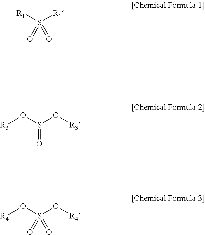
The G band/D band ratio of the carbon-based active material may be greater than 2, the electrolyte solution may include at least one S═O-containing compound represented by one of the following Chemical Formulae 1 to 3:
Figure US10587006-20200310-C00001
R1 and R1′ may be each independently a substituted or unsubstituted hydrocarbon group having a carbon number of 1 or 2, R3 and R3′ may be each independently a substituted or unsubstituted hydrocarbon group having a carbon number of 1 or 2, and R4 and R4′ may be each independently a substituted or unsubstituted hydrocarbon group having a carbon number of 1 or 2.
The G band/D band ratio of the carbon-based active material may be less than or equal to 2, the electrolyte solution may include at least one S═O-containing compound represented by the following Chemical Formula 4 or 5:
Figure US10587006-20200310-C00002
one of R5 or R5′ may be a substituted or unsubstituted hydrocarbon group having a carbon number of 3 or more, and another of R5 or R5′ may be a substituted or unsubstituted hydrocarbon group having a carbon number of 1 or 2, and R2 may be a substituted or unsubstituted hydrocarbon group having a carbon number of 1 or more.
The electrolyte solution may further include an additive, the additive including a compound represented by one of the following Chemical Formula 1a or 1b:
Figure US10587006-20200310-C00003
X may be a Group 13 element, a Group 14 element, or a Group 15 element, Y may be a Group 16 element, and R1 to R3 may be each independently a substituted or unsubstituted C1 to C4 alkyl group.
The electrolyte solution may further include an additive, the additive including a compound represented by the following Chemical Formula 2a:
Figure US10587006-20200310-C00004
A may be a Group 1A element, a Group 2A element, or aluminum, M may be a transition metal, a Group 3B element, a Group 4B element, or a Group 5B element, R4 may be a halogen, Z may be —OC—R51—CO—, —OC—C(R52)2—, or —OC—CO—, in which R51 is an alkylene group, a halogenated alkylene group, an arylene group, or a halogenated arylene group, and each R52 is independently an alkyl group, a halogenated alkyl group, an aryl group, or a halogenated aryl group, a may be an integer of 1 to 4, b may be 0, 2, or 4, and c, d, m, and n may be each independently integers of 1 to 3.
The electrolyte solution may include a first additive, the first additive including a compound represented by one of Chemical Formula 1a or 1b, and a second additive, the second additive including a compound represented by Chemical Formula 2a:
Figure US10587006-20200310-C00005
X may be a Group 13 element, a Group 14 element, or a Group 15 element, Y may be a Group 16 element, and R1 to R3 may be each independently a substituted or unsubstituted C1 to C4 alkyl group,
Figure US10587006-20200310-C00006
A may be a Group 1A element, a Group 2A element, or aluminum, M may be a transition metal, a Group 3B element, a Group 4B element, or a Group 5B element, R4 may be a halogen, Z may be —OC—R51—CO—, —OC—C(R52)2—, or —OC—CO—, in which R51 is an alkylene group, a halogenated alkylene group, an arylene group, or a halogenated arylene group, and each R52 is independently an alkyl group, a halogenated alkyl group, an aryl group, or a halogenated aryl group, a may be an integer of 1 to 4, b may be 0, 2, or 4, and c, d, m, and n may be each independently integers of 1 to 3.
X may be boron or phosphorus, and Y may be oxygen.
The additive may include tris(trifluoromethyl)phosphoric acid.
M may be boron or phosphorus.
The additive may include at least one of lithium difluoro(oxalato-O,O′)borate and lithium difluoro bis(oxalato-O,O′)phosphate.
The additive may be included in the electrolyte solution in an amount of about 1 wt % to about 4 wt %, based on a total weight of the electrolyte solution.
The additive may be included in the electrolyte solution in an amount of greater than or equal to about 0.25 wt %, based on a total weight of the electrolyte solution.
The first additive may be included in the electrolyte solution in an amount of about 1 wt % to about 4 wt %, based on a total weight of the electrolyte solution, the second additive may be included in the electrolyte solution in an amount of greater than or equal to about 0.25 wt %, based on the total weight of the electrolyte solution, and a total weight of the first additive and the second additive in the electrolyte solution may be less than or equal to 5 wt %, based on the total weight of the electrolyte solution.
The electrolyte solution may include hydrofluoroether.
The electrolyte solution may include at least one of a linear carbonate ester or a fluoro ethylene carbonate.
The negative active material may include a silicon-based active material.
The silicon-based active material may include Si, a Si-based alloy, SiOx, in which 0<x<2, or a combination thereof.
BRIEF DESCRIPTION OF THE DRAWINGS
Features will be apparent to those of skill in the art by describing in detail exemplary embodiments with reference to the attached drawings in which:
FIG. 1 illustrates a cross-sectional view of a rechargeable lithium ion battery according to an exemplary embodiment.
FIG. 2 illustrates a graph showing a correspondence relation between specific capacity of the rechargeable lithium ion battery and potential of a negative active material.
FIG. 3 illustrates a graph showing a correspondence relation between the potential of the negative active material and dQ/dV.
FIG. 4 illustrates a graph showing a correspondence relation between the potential of the negative active material and dQ/dV.
FIG. 5 illustrates a graph showing a correspondence relation between the potential of the negative active material and dQ/dV.
FIG. 6 illustrates a graph showing a correspondence relation between the number of cycles of the rechargeable lithium ion battery and its discharge capacity.
FIG. 7 illustrates a graph showing correspondence relationship between the number of cycles of the rechargeable lithium ion battery and its discharge capacity.
FIG. 8 illustrates a graph showing correspondence relationship between the number of cycles of the rechargeable lithium ion battery and its discharge capacity.
FIG. 9 illustrates a graph showing correspondence relationship between the number of cycles of the rechargeable lithium ion battery and its discharge capacity.
DETAILED DESCRIPTION
Example embodiments will now be described more fully hereinafter with reference to the accompanying drawings; however, they may be embodied in different forms and should not be construed as limited to the embodiments set forth herein. Rather, these embodiments are provided so that this disclosure will be thorough and complete, and will fully convey exemplary implementations to those skilled in the art.
In the drawing figures, the dimensions of layers and regions may be exaggerated for clarity of illustration. Like reference numerals refer to like elements throughout.
Structure of Rechargeable Lithium Ion Battery
The structures of a rechargeable lithium ion battery 10 according to an embodiment are described with a reference with FIG. 1.
A rechargeable lithium ion battery 10 may include a positive electrode 20, a negative electrode 30, and a separator layer 40. The rechargeable lithium ion battery 10 may have a charge-reaching voltage of (e.g., an oxidation reduction potential), for example, greater than or equal to about 4.3 V (vs. Li/Li+) and less than or equal to about 5.0 V, e.g., greater than or equal to about 4.5 V and less than or equal to about 5.0 V. The rechargeable lithium ion battery 10 has no particular limit to a shape. For example, the rechargeable lithium ion battery 10 may have a suitable shape such as a cylinder, a prism laminate-type, a button, and the like.
The positive electrode 20 may include a current collector 21 and a positive active material layer 22.
The current collector 21 may be a suitable conductor, and may include, e.g., aluminum, stainless steel, or nickel plated steel. The positive active material layer 22 may include at least one positive active material, and may further include a conductive agent a binder.
The positive active material may include, e.g., a lithium-containing solid solution oxide. In an implementation, the positive active material may include a suitable material that electrochemically intercalates and deintercalates lithium ions without limitation.
The solid solution oxide may include, e.g., LiaMnxCoyNizO2 (1.150≤a≤1.430, 0.45≤x≤0.6, 0.10≤y≤0.15, 0.20≤z≤0.28), LiMnxCoyNizO2 (0.3≤x≤0.85, 0.10≤y≤0.3, and 0.10≤z≤0.3), or LiMn1.5Ni0.5O4.
The positive active material may be included in the positive electrode in an amount of, e.g., about 85 wt % to about 96 wt % or about 88 wt % to about 94 wt %, based on a total weight of the positive electrode active mass (e.g., the positive active material, the binder, and the conductive agent). When the positive active material is included within the range, battery characteristics (e.g., cycle-life and storage capacity) may be particularly improved.
The conductive agent may include, e.g., carbon black Ketjen black, acetylene black, or the like, natural graphite, artificial graphite, or the like. In an implementation, the conductive agent may include a suitable material that helps improve conductivity of a positive electrode.
The conductive agent may be included in the positive active material in an amount of, e.g., about 3 wt % to about 10 wt % or about 4 wt % to about 6 wt %, based on the total weight of the positive electrode active mass. When the conductive agent is included within the range, battery characteristics may be particularly improved.
The binder may include, e.g., polyvinylidene fluoride, an ethylene-propylene-diene terpolymer, a styrene-butadiene rubber, an acrylonitrile-butadiene rubber, fluororubber, polyvinyl acetate, polymethyl methacrylate, polyethylene, nitrocellulose, or the like. In an implementation, the binder may include a suitable material that binds the positive active material and the conductive agent on the current collector 21.
The binder may be included in the positive electrode active material in an amount of, e.g., about 3 wt % to about 7 wt % or about 4 wt % to about 6 wt %, based on the total weight of the positive electrode active mass. When the binder is included within the range, battery characteristics may be particularly improved.
The positive active material layer 22 may have a suitable density (g/cm3), e.g., about 2.0 to about 3.0 or about 2.5 to about 3.0. When the positive active material layer 22 has density within the range, battery characteristics may be particularly improved.
Maintaining the density at about 3.0 g/cm3 or less may help prevent destruction of particles of the positive active material, thereby helping to prevent a loss in an electric contact among themselves. As a result, a utilization rate of the positive active material may be maintained and original discharge capacity may be obtained or maintained, and undesirable polarization may be avoided. In addition, charging of the positive active material up to greater than or equal to a predetermined potential may be avoided, thereby reducing and/or preventing decomposition of an electrolyte solution or elution of a transition metal as an active material, and preventing a deterioration in cycle characteristics. In this view, the positive active material layer 22 may have desirable density within the range.
The density of the positive active material layer 22 may be obtained by dividing planar density of the positive active material layer 22 after the compression by a thickness of the positive active material layer 22 after the compression.
The positive active material layer 22 may be manufactured, e.g., according the following method. For example, a positive electrode active mass may first be manufactured by dry-mixing a positive active material, a conductive agent, and a binder. Subsequently, the positive electrode active mass may be dispersed in a suitable organic solvent to form a positive electrode active mass slurry, and the positive electrode active mass slurry may be coated on a current collector 21, dried, and compressed to form a positive active material layer.
The negative electrode 30 may include a current collector 31 and a negative active material layer 32. The current collector 31 may include a suitable conductor, e.g., aluminum, stainless steel, or nickel plated steel.
The negative active material layer 32 may include at least one negative active material, and may further include a binder. The negative active material may include, e.g., a silicon-containing silicon-based active material and a carbon-based active material. For example, when the negative active material is formed of only the silicon-based active material, battery characteristics may not be sufficiently increased.
The battery characteristics may be improved by adding a S═O-containing compound to an electrolyte solution. The S═O-containing compound may have a structure that depends on a G band/D band ratio of the carbon-based active material, which will be described in detail below.
The silicon-based active material may include silicon (e.g., silicon atoms) and may be a material that electrochemically intercalates and deintercalates lithium ions. The silicon active material may include, e.g., a particulate of silicon elementary substance, a particulate of silicon oxide, an alloy including silicon as a basic material, or the like. The silicon oxide may be represented by SiOx (0≤x≤2). The alloy including silicon as a basic material may include silicon in a wt % of the total metal elements, based on a total weight of the alloy, e.g., a Si—Al—Fe alloy.
The carbon-based active material may include carbon (e.g., a material having carbon atoms), and may also be a material that electrochemically intercalates and deintercalates lithium ions. The carbon-based active material may include, e.g., a graphite active material (e.g., artificial graphite, natural graphite, a mixture of artificial graphite and natural graphite, natural graphite coated with artificial graphite, or the like), or the like.
The carbon-based active material may have an intrinsic G band/D band ratio or G band/D band ratio. For example, two peaks (G band and D band) are shown in the Raman spectrum of the carbon-based active material. The G band is a peak observed in a wave number range of about 1580±20 cm−1, and the D band is a peak observed in a wave number range of about 1355±20 cm−1. Then, the G band/D band ratio may be obtained by dividing an area of the G band by an area of the D band.
The area of each peak may be obtained by, e.g., mensuration by division. As the G band/D band ratio is higher, the carbon-based active material may have high reactivity (e.g., may more easily decompose the solvent of the rechargeable lithium ion battery).
Accordingly, the battery characteristics of the rechargeable lithium ion battery may be remarkably improved by including a S═O-containing compound (that has a different structure depending on a G band/D band ratio of the carbon-based active material) in an electrolyte solution, which will be described in detail below.
The silicon-based active material and the carbon-based active material of the negative active material may be included in a suitable weight ratio. For example, the negative active material may be silicon-rich, carbon-rich, or about even.
The negative active material may be included in the negative electrode active material in an amount of about 90 wt % to about 98 wt %, based on a total weight of the negative electrode active mass (the negative active material and the binder). When the negative active material is included within the range, battery characteristics may be particularly improved.
The binder may include the same as the binder of the positive active material layer 22. When the positive active material layer 22 is coated on a current collector 21, carboxylmethyl cellulose (hereinafter, CMC) as a thickener may be used in an amount of greater than or equal to about 1/10 of the binder and less than and equal to the amount of the binder. The binder including the thickener may be used in an amount of about 1 wt % and less than or equal to about 10 wt %, based on the total weight of the negative electrode active mass. When the binder including the thickener is used within the range, battery characteristics may be particularly improved.
The negative active material layer 32 may have a suitable density (g/cm3), e.g., about 1.0 to about 2.0. When the negative active material layer 32 has density within the range, battery characteristics may be particularly improved. The negative active material layer 32 may be formed by, e.g., dispersing the negative active material and the binder into a suitable solvent (e.g., N-methyl-2-pyrrolidone or water) to form a slurry, coating this slurry on the current collector 31, and drying it. The density of the negative active material layer 32 may be obtained by dividing planar density of the negative active material layer 32 by after the compression by thickness of the negative active material layer 32 after the compression.
A separator layer 40 may include a separator 40 a and an electrolyte solution 43. The separator 40 a may include a substrate 41 and a porous layer 42. The substrate 41 may be formed of a material selected from, e.g., polyethylene, polypropylene, or the like, and may include a plurality of first pores (e.g., minute pores) 41 a.
The first pores 41 a may have a spherical shape, as illustrated in FIG. 1, or may have various other suitable shapes. The first pores 41 a may have a spherical diameter of, e.g., about 0.1 μm to about 0.5 μm. The spherical diameter of the first pores 41 a may correspond to the diameter of a sphere, e.g., when the first pores 41 a are regarded as the sphere. The first pores 41 a may be measured by, e.g., an automatic porosimeter AutoporeIV (Shimadzu Corporation). This measuring device may be used to measure, e.g., a diameter distribution of the first pores 41 a, and a diameter having the highest distribution may be regarded as a representative value.
The spherical diameter of the pores 41 a in the surface layer of the substrate 41 may be measured by, e.g., a scanning electron microscope JSM-6060 (JEOL Ltd.). This measuring device measures, e.g., the diameter of each first pore 41 a in the surface layer.
The substrate 41 may have porosity of, e.g., about 38-44%. When the substrate 41 has porosity within this range, cycle-life may be particularly improved. The porosity of the substrate 41 may be obtained by dividing the entire volume of the first pores 41 a by the total volume of the substrate 41 (e.g., the total volume of the resin part and the first pores 41 a of the substrate 41).
The porosity of the substrate 41 may be measured by, e.g., an automatic porosimeter AutoporeIV (Shimadzu Corporation). The substrate 41 may be about 6 μm to about 19 μm thick. When the substrate 41 has a thickness within the range, cycle-life may be particularly improved.
The porous layer 42 may be formed of a different material from the substrate 41, e.g., polyvinylidene fluoride, polyamideimide, aramid (aromatic polyamide) or the like, and may include a plurality of second pores (e.g., minute pores) 42 a. In an implementation, the second pores 42 a have a spherical shape as illustrated in FIG. 1, or may have various other suitable shapes.
The second pores 42 a may be different from the first pores 41 a, for example, the second pores 42 a may have a larger diameter and porosity than the first pores 41 a. In an implementation, the second pores 42 a may have a diameter of, e.g., about 1 μm to about 2 μm.
The second pores 42 a may have the diameter of a sphere when the second pore 42 a is regarded as a sphere and is measured by, e.g., a scanning electron microscope JSM-6060 (Joel Ltd.). This measuring device may measure the diameter of each second pore 42 a.
Polyvinylidene fluoride applied to the porous layer 42 may include, e.g., KF polymer #1700, #9200, #9300, or the like (KUREHA CORPORATION). The polyvinylidene fluoride may have a weight average molecular weight of, e.g., about 500,000-1,000,000. The porous layer 42 may be directly synthesized or commercially available.
The separator 40 a may have porosity of, e.g., about 39% to about 58%. When the separator 40 a has porosity within this range, cycle-life may be particularly improved. Herein, the porosity of the separator 40 a may be obtained by dividing the total volume of the first pores 41 a and second pores 42 a by the total volume of the separator 40 a (e.g., the total volume of the resin part and the first pores 41 a of the substrate 41 a and the resin part of the and the second pores 42 a of the porous layer 42). The porosity of the separator 40 a may be measured with, e.g., an automatic porosimeter AutoporeIV (Shimadzu Corporation). The porosity of the separator 40 a may be larger than the porosity of the substrate 41, and the porosity of the porous layer 42, e.g., the porosity of the second pores 42 a, may be higher than the porosity of the substrate 41, e.g., the porosity of the first pores 41 a.
The porous layer 42 may be about 1 μm to about 5 μm thick. The thickness of the separator 40 a, e.g., the sum of the thickness of the substrate 41 and the thickness of the porous layer 42 may be about 10 μm to 25 μm. When the porous layer 42 or the separator 40 a has a thickness within these ranges, cycle-life may be particularly improved.
In an implementation, the porous layer 42 may be positioned on sides, e.g., both sides, of the substrate 41, e.g., on the side of the positive electrode 20 and the side of the negative electrode 30 in FIG. 1, but at least on the side of the negative electrode 30. In terms of cycle-life improvement of a rechargeable lithium ion battery, the porous layer 42 may be formed on both sides of the substrate 41.
The substrate 41 may have suitable air permeability (e.g., air permeability defined as JIS P8117), about 250 sec/100 cc to about 300 sec/100 cc. In an implementation, the substrate 40 a may have an air permeability of, e.g., about 220 sec/100 cc to about 340 sec/100 cc. When the substrate 41 and the separator 40 a have air permeability within the ranges, cycle-life may be particularly improved. The air permeability of the substrate 41 and the separator 40 a is measured with, e.g., a Gurley-type air permeability meter G-B2 (TOYOSEIKI CO., LTD).
The separator 40 a may be formed by, e.g., coating a coating solution (including a resin and a water-soluble organic solvent) on the substrate 41 to form the porous layer 42 and then, coagulating the resin and removing the water-soluble organic solvent. In this way, the separator 40 a may have a multi-layer structure of the substrate 41 and the porous layer 42 but a single structure (for example, a structure of only the substrate 41).
The electrolyte solution 43 may include a lithium salt, a solvent, and an additive. The additive may include the S═O-containing compound. The lithium salt may be an electrolyte of the electrolyte solution 43. The lithium salt may include, e.g., LiClO4, LiBF4, LiAsF6, LiSbF6, LiSO3CF3, LiN(SO2CF3), LiN(SO2CF2CF3), LiC(SO2CF2CF3)3, LiC(SO2CF3)3, LiI, LiCl, LiF, LiPF5(SO2CF3), LiPF4(SO2CF3)2, or the like, as well as lithium hexafluoro phosphate (LiPF6). In an implementation, the lithium salt may include, e.g., LiPF6, LiClO4, LiBF4, LiAsF6, or LiSbF6. When these lithium salts are dissolved in the electrolyte solution 43, battery characteristics may be particularly improved.
In the electrolyte solution 43, any one lithium salt or more than one lithium salt may be dissolved therein among the above lithium salts.
The lithium salt may be dissolved in a concentration of about 1.15 mol/L to about 1.5 mol/L (e.g., the concentration sum of the lithium salts when more than one lithium salt is dissolved in the electrolyte solution 43). In an implementation, the concentration may be, e.g., about 1.3 mol/L to about 1.45 mol/L. When the lithium salt is included with the concentration range, battery characteristics may be particularly improved.
The solvent may include various kinds of suitable non-aqueous solvent for a rechargeable lithium ion battery. The solvent may include, e.g., at least one of hydrofluoroether (HFE), linear carbonate ester, or fluoro ethylene carbonate.
The hydrofluoroether is an ether where a part of hydrogen is substituted with a fluorine, and may have improved oxidation resistance. Considering resistance for a charge voltage and current density of a positive electrode material, the hydrofluoroether may include, e.g., 2,2,2-trifluoroethylmethylether (CF3CH2OCH3), 2,2,2-trifluoroethyl difluoromethyl ether (CF3CH2OCHF2), 2,2,3,3,3-pentafluoropropylmethylether (CF3CF2CH2OCH3), 2,2,3,3,3-pentafluoropropyldifluoromethyl ether (CF3CF2CH2OCHF2), 2,2,3,3,3-penta fluoropropyl-1,1,2,2-tetrafluoroethyl ether (CF3CF2CH2OCF2CF2H), 1,1,2,2-tetrafluoro ethylmethylether (HCF2CF2OCH3), 1,1,2,2-tetrafluoro ethylethylether (HCF2CF2OCH2CH3), 1,1,2,2-tetrafluoro ethylpropylether (HCF2CF2OC3H7), 1,1,2,2-tetrafluoro ethylbutylether (HCF2CF2OC4H9), 1,1,2,2-tetrafluoro ethylisobutylether (HCF2CF2OCH2CH(CH3)2), 1,1,2,2-tetrafluoro ethylisopentylether (HCF2CF2OCH2C(CH3)3), 1,1,2,2-tetrafluoroethyl-2,2,2-trifluoro ethylether (HCF2CF2OCH2CF3), 1,1,2,2-tetrafluoroethyl-2,2,3,3-tetrafluoro propylether (HCF2CF2OCH2CF2CF2H), hexafluoro isopropylmethylether ((CF3)2CHOCH3), 1,1,3,3,3-pentafluoro-2-trifluoro methylpropylmethylether ((CF3)2CHCF2OCH3), 1,1,2,3,3,3-hexafluoro propylmethylether (CF3CHFCF2OCH3), 1,1,2,3,3,3-hexafluoro propylethylether (CF3CHFCF2OCH2CH3) or 2,2,3,4,4,4-hexafluoro butyldifluoromethylether (CF3CHFCF2CH2OCHF2). The hydrofluoroether may include one of these materials or a mixture of these materials. The hydrofluoroether may be included in the electrolyte solution in an amount of about 10 volume % to about 60 volume %, e.g., about 30 volume % to about 50 volume %, based on a total volume of the solvent of the electrolyte solution 43. When the hydrofluoroether is included within the described volume ratio, battery characteristics may be particularly improved.
The linear carbonate ester may be a carbonate ester having a linear structure. The linear carbonate ester may include, e.g., dimethyl carbonate, ethyl methyl carbonate, or diethyl carbonate. In an implementation, the electrolyte solution 43 may include one kind of the linear carbonate ester. The linear carbonate ester may be included in the electrolyte solution in an amount of about 5 volume % to 60 volume %, e.g., about 20 volume % to about 50 volume %, based on the total volume of the electrolyte solution 43. When the linear carbonate ester is included within the volume ratio, battery characteristics may be particularly improved.
The fluoro ethylene carbonate may be included in the electrolyte solution in an amount of about 10 volume % to about 30 volume %, e.g., about 15 volume % to about 20 volume %, based on the total volume of the electrolyte solution 43. When the fluoro ethylene carbonate, e.g., mono fluoro ethylene carbonate, is included in this amount, cycle-life may be particularly improved. In an implementation, the electrolyte solution 43 may additionally include suitable non-aqueous solvents used in a rechargeable lithium ion battery.
According to one embodiment, the S═O-containing compound is a compound including an S═O structure or moiety. The S═O-containing compound may have a different structure, depending on the G band/D band ratio of a carbon-based active material. In an implementation, a rechargeable lithium ion battery may be manufactured by using a lithium foil as a positive active material, a mixture of a silicon-based active material and a carbon-based active material as a negative active material, and ethylene carbonate as a solvent. After the rechargeable lithium ion battery is charged and discharged more than once, a correlation between behavior of the rechargeable lithium ion battery and, e.g., potential (based on Li/Li+), of the negative active material, and dQ/dV may be examined. As a result, when the negative active material has a potential of about 0.4 V during the charge of the rechargeable lithium ion battery, the dQ/dV may become disordered. In an implementation, the potential of the negative active material may be changed in a range of about 0.5 V to 10 mV after the 2nd charge and discharge.
As a result, the solvent (e.g., ethylene carbonate) may be decomposed in or at the negative active material during every charge, e.g., at least during the charge. The reason for insufficient battery characteristics may be that a decomposition product of the solvent may be deposited on the negative active material and may hinder lithium ions from getting in and out of the negative active material. Accordingly, an additive that satisfies the following three conditions may be added to the electrolyte solution.
The additive may be decomposed earlier than the solvent during the charge (e.g., at a higher potential than that of the solvent).
A product generated during the decomposition may help suppress the decomposition of the solvent. For example, the decomposition product of the additive may cover the negative active material and may help prevent contact between the solvent and the negative active material.
The decomposition product may not, or only to a small degree, hinder lithium ions from getting in and out of the negative active material.
An additive satisfying the above conditions is described below.
The following experiment was performed based on an S═O-containing compound (a compound including at least one S═O bond). For example, a rechargeable lithium ion battery was manufactured by using a lithium foil as a positive active material, a mixture of a silicon-based active material and a carbon-based active material as a negative active material, and ethylene carbonate as a solvent (e.g., for an electrolyte solution). In addition, the S═O-containing compound was added to an electrolyte solution. Then, the rechargeable lithium ion battery was charged and discharged more than once, and then, a correlation between behavior of the rechargeable lithium ion battery, e.g., potential of the negative active material (based on Li/Li+), and dQ/dV was examined.
As a result, when the rechargeable lithium ion battery had a potential of higher than about 0.4V during the charge, the dQ/dV became disordered, and when the rechargeable lithium ion battery had a potential of about 0.4V, the dQ/dV was almost not disordered. In addition, battery characteristics of the rechargeable lithium ion battery were clearly improved (see the below-described Examples).
Accordingly, the S═O-containing compound may be decomposed earlier than the solvent, and its decomposition product may help suppress decomposition of the solvent and may not hinder lithium ions from getting in and out of the negative active material. For example, the S═O-containing compound may satisfy the above three conditions.
In an implementation, a kind of the carbon-based active material may vary as described above. The carbon-based active materials may be selected depending on energy density or desired usage of the rechargeable lithium ion battery. Accordingly, the rechargeable lithium ion battery 10 according to an embodiment may correspond to or include various carbon-based active materials in order to be put into use.
The carbon-based active material may have a larger specific surface area than the silicon-based active material, and the carbon-based active material may significantly decompose the solvent (or the S═O-containing compound), e.g., to a greater degree, compared with the silicon-based active material. Accordingly, the S═O-containing compound may endure consumption (e.g., decomposition) on the carbon-based active material and may help suppress decomposition of the solvent.
Accordingly, an S═O-containing compound according to an embodiment may be capable of improving battery characteristics despite use of any carbon-based active material as a negative active material. For example, the carbon-based active material could massively dissolve the solvent (or the S═O-containing compound), and a correlation between a G band/D band ratio of the carbon-based active material and the S═O-containing compound based on the G band/D band ratio may be a parameter showing reactivity of the carbon-based active material.
As a result, the desirability of various S═O-containing compounds was found out to vary depending on the G band/D band ratio of the carbon-based active material. For example, the S═O-containing compound may be classified into 4 upper limits (e.g., groups or divisions) based on the G band/D band ratio of the carbon-based active material, as shown in the following Table 1.
TABLE 1
G/D S═O Compound
ratio Effective
Gr >2 [—S═O(═O)]  
Figure US10587006-20200310-C00007
[—OS═O(═O)] [—O(O)S═O]  
Figure US10587006-20200310-C00008
[—O(O)S═O(═O)]  
Figure US10587006-20200310-C00009
≤2 [—S═O(═O)]  
Figure US10587006-20200310-C00010
[—OS═O(═O)]  
Figure US10587006-20200310-C00011
[—O(O)S═O] [—O(O)S═O(═O)]
G/D S═O Compound
ratio Non effective
Gr >2 [—S═O(═O)]  
Figure US10587006-20200310-C00012
[—OS═O(═O)] [—O(O)S═O] [—O(O)S═O(═O)]
≤2 [—S═O(═O)] [—OS═O(═O)]  
Figure US10587006-20200310-C00013
[—O(O)S═O] [—O(O)S═O(═O)]
Herein, in Table 1, “Gr” refers to a carbon-based active material.
In addition, “effective” refers to improvement of battery characteristics, compared with a rechargeable lithium ion battery using an electrolyte solution without a S═O-containing compound, and “non effective” refers to equivalent or lower battery characteristics than the rechargeable lithium ion battery using an electrolyte solution without a S═O-containing compound.
A structure formula in the bracket indicates an S═O bond.
In addition, the first upper limit or division corresponds to a G band/D band ratio>2 and simultaneously, to “effective”, and the second upper limit or division corresponds to the G band/D band ratio≤2 and simultaneously, to “effective”. The third upper limit or division corresponds to the G band/D band ratio>2 and simultaneously, to “non effective”, and the fourth upper limit or division corresponds to the G band/D band ratio≤2 and simultaneously, to “non effective.”
The S═O-containing compound of the first division may be represented by one of the following Chemical Formulae 1 to 3.
Figure US10587006-20200310-C00014
Herein, R1 and R1′ may each independently be a C1 or C2 hydrocarbon group, and at least one part of hydrogen atoms of R1 and R1′ may be substituted. R3 and R3′ may each independently be a C1 or C2 hydrocarbon group, may be linked to each other, or at least one part of hydrogen atoms of R3 and R3′ may be substituted. R4 and R4′ may each independently be a C1 or C2 hydrocarbon group, or at least one part of hydrogen atoms of R4 and R4′ may be substituted.
The S═O-containing compound represented by Chemical Formula 1 may be, e.g., ethylmethylsulfone (EMS), diethyl sulfone (DES), or the like. The S═O-containing compound represented by Chemical Formula 2 may be, e.g., dimethyl sulfurous acid (DMSI), diethyl sulfurous acid (DESI), ethylene sulfurous acid (ES), or the like. The S═O-containing compound represented by Chemical Formula 3 may be, e.g., dimethyl sulfuric acid (DMSA), diethyl sulfuric acid (DESA), or the like.
The S═O-containing compound of the second division may be represented by one of the following Chemical Formulae 4 and 5.
Figure US10587006-20200310-C00015
Herein, one of R5 and R5′ may be a hydrocarbon group having a carbon number of 3 or more, another may be a C1 or C2 hydrocarbon group, and at least one part of hydrogen atoms of R5 and R5′ may be substituted. R2 may be a hydrocarbon group having a carbon number of 1 or more, and at least one part of hydrogen atoms of R2 may be substituted.
The S═O-containing compound represented by Chemical Formula 4 may be, e.g., ethylisopropylsulfone (EiPS), ethylbutylsulfone (EBS) and butylisopropylsulfone (BiPS), or the like. The S═O-containing compound represented by Chemical Formula 5 may be, e.g., butane sultone (BS), or the like.
The S═O-containing compound of the third division may be, e.g. sulfolane (SL), and the S═O-containing compound of the fourth upper limit may be, e.g. propanesultone (PS).
Accordingly, in the present exemplary embodiment, the electrolyte solution 43 may include at least one S═O-containing compound of the first division when the carbon-based active material has a G band/D band ratio of greater than about 2.
In an implementation, when the carbon-based active material has a G band/D band ratio of less than or equal to about 2, the electrolyte solution 43 may include at least one S═O-containing compound of the second division.
The S═O-containing compound may be included in the electrolyte in an amount of about 0.5 volume % to about 5.0 volume %, e.g., about 3.0 volume % to about 5.0 volume % or about 3.0 volume %, based on a total volume of the solvent.
Maintaining the amount of the S═O-containing compound at about 0.5 volume % or greater may help ensure that the S═O-containing compound has sufficient effects. Maintaining the amount of the S═O-containing compound at about 5 volume % or less may help prevent an undesirably excessive increase in viscosity of the electrolyte solution. Thus electrolyte solution may be sufficiently soaked in each active material, and deterioration in ion conductivity of the electrolyte solution and discharge capacity may be reduced and/or prevented.
In an implementation, various additives may be added to the electrolyte solution 43. The additives may include, e.g., an additive for a cathodic behavior, an additive for an anodic behavior, an ester-based additive, a carbonate ester-based additive, a sulfate ester-based additive, a phosphate ester-based additive, a borate ester-based additive, an acid anhydride-based additive, an electrolyte-based additive, or the like.
One of these additives may be added to the electrolyte solution 43 alone, or a mixture of more than one thereof may be added thereto. The additives may be added in an amount of, e.g., 0.01 wt % to about 5.0 wt % based on the total weight of an electrolyte and a solvent (including the S═O-containing compound) of the electrolyte solution 43. When the additives are added within this range, battery characteristics may be particularly improved.
For example, the electrolyte solution 42 may include a first additive represented by the following Chemical Formula 1a or 1b.
Figure US10587006-20200310-C00016
In the above Chemical Formulae 1a and 1b,
X may be an element selected from a Group 13 element, a Group 14 element, and a Group 15 element,
Y may be a Group 16 element, and
R1 to R3 may be independently a substituted or unsubstituted C1 to C4 alkyl group.
In an implementation, the electrolyte solution 43 may include one kind or more than one kind of the first additive.
In the above Chemical Formulae 1a and 1b, X may be one kind of element selected from the group consisting of a Group 13 element, a Group 14 element and a Group 15 element, e.g., boron or phosphorus.
Y may be a Group 16 element, e.g., oxygen. R1 to R3 may be each independently a substituted or unsubstituted C1 to C4 alkyl group. Examples of the first additive may include compounds represented by the following Chemical Formulae 1-1 to 1-3.
Hereinafter, an additive having a structure represented by Chemical Formula 1-1 is referred to be an additive 1-1, an additive having a structure represented by Chemical Formula 1-2 is referred to be an additive 1-2, and an additive having a structure represented by Chemical Formula 1-3 is referred to be an additive 1-3.
Figure US10587006-20200310-C00017
In an implementation, electrolyte solution 43 may include a second additive represented by the following Chemical Formula 2a.
Figure US10587006-20200310-C00018
In the above Chemical Formula 2a,
A may be an element selected from a Group 1A element, a Group 2A element, and aluminum, in a short form of the Periodic Table,
M may be element selected from a transition metal, a Group 3B element, a Group 4B element, and a Group 5B element in a short form of the Periodic Table,
R4 may be a halogen element,
Z may be —OC—R51—CO—, —OC—C(R52)2—, or —OC—CO—, in which R51 may be an alkylene group, a halogenated alkylene group, an arylene group, or a halogenated arylene group, and each R52 may independently be an alkyl group, a halogenated alkyl group, an aryl group, or a halogenated aryl group,
a may be an integer of 1 to 4,
b may be 0, 2, or 4, and
c, d, m, and n may each independently be integers of 1 to 3.
In an implementation, the electrolyte solution 43 may include one kind or more than one kind of the second additive.
In the above Chemical Formula 2a, A may be one kind of element selected from a Group 1A element, a Group 2A element, and aluminum in a short form of the Periodic Table. M may be one kind element selected from transition metal, a Group 3B element, a Group 4B element, a Group 5B element in a short form of the Periodic Table, e.g., boron or phosphorus.
R4 may be a halogen, Z may be —OC—R51—CO—, —OC—C(R52)2—, or —OC—CO—, in which R51 may be an alkylene group, a halogenated alkylene group, an arylene group, or a halogenated arylene group, and each R52 may independently be an alkyl group, a halogenated alkyl group, an aryl group, or a halogenated aryl group,
a may be an integer of 1 to 4, b may be 0, 2, or 4, and c, d, m, and n may each independently be integers of 1 to 3. Examples of the second additive may include, e.g., compounds represented by the following Chemical Formulae 2-1 to 2-5. Hereinafter, an additive having a structure represented by Chemical Formula 2-1 is referred to be an additive 2-1, an additive having a structure represented by Chemical Formula 2-2 is referred to be an additive 2-2, and an additive having a structure represented by Chemical Formula 2-3 is referred to be an additive 2-3. In addition, an additive having a structure represented by Chemical Formula 2-4 is referred to be an additive 2-4, and an additive having a structure represented by Chemical Formula 2-5 is referred to be an additive 2-5.
Figure US10587006-20200310-C00019
In an implementation, the electrolyte solution may include the first additive represented by the above Chemical Formula 1a or 1b, and the second additive represented by the above Chemical Formula 2a.
An electrolyte solution was manufactured by mixing fluoro ethylene carbonate (FEC), dimethyl carbonate (DMC), and HFE (herein, H(CF2)2OCH2(CF2)2H) in a volume ratio of 15:45:40 to prepare a solvent, and dissolving lithium hexafluoro phosphate in a concentration of 1.3 mol/L therein. Then, a lithium foil was used as a positive active material, and a silicon-based active material or a carbon-based active material was used as the negative active material, and the electrolyte solution was used to manufacture a rechargeable lithium ion battery cell for a test.
The rechargeable lithium ion battery cell was charged and discharged once according to a charge and discharge curved line shown in FIG. 2. A graph (L1) is a curved line, e.g., a discharge curved line showing a correlation between a potential of the carbon-based active material (based on Li/Li+, hereinafter, the same) and discharge capacity of the rechargeable lithium ion battery cell during the discharge. A graph (L2) is a curved line, e.g., a charge curved line showing potential of the carbon-based active material and discharge capacity of the rechargeable lithium ion battery cell during the charge. A graph (L3) is a discharge curved line of the silicon-based active material, and a graph (L4) is a charge curved line of the silicon-based active material.
Then, a correlation between behavior of each rechargeable lithium ion battery cell during the charge, e.g., potential of the negative active material and dQ/dV (quantity of electricity relative to a potential change) was examined. The results are provided in FIG. 3. A graph (L5) shows a correlation between potential of the carbon-based active material and the dQ/dV, and a graph (L6) shows a correlation between a potential of the silicon-based active material and the dQ/dV.
The graph showing a correlation between potential of the negative active material and the dQ/dV shows disorder (peak) when the solvent was decomposed. In addition, the solvent was less decomposed, as the dQ/dV was less changed, until the rechargeable lithium ion battery was full-charged.
As shown in the graph (L5), when the carbon-based active material was used as a negative active material, the negative active material showed a peak (disordered) (A1) in the dQ/dV at a potential of about 1.7 V to about 2.0 V and another peak (A2) in the dQ/dV at 0.6 V. The peak (A1) was caused by decomposition of HFE, and the peak (A2) was caused by decomposition of FEC. On the other hand, when silicon-based active material was used as a negative active material, the dQ/dV was deteriorated down to a potential of less than or equal to about 1.05 V.
As a result, when the carbon-based active material was used as a negative active material, the HFE was first decomposed on the negative active material, and then, the FEC was decomposed as the rechargeable lithium ion battery cell charged. In addition, the HFE was decomposed but did not form a valid passivation film on the carbon-based active material (e.g., did not suppress decomposition of the solvent). Furthermore, when the silicon-based active material was used as a negative active material, all the solvent was decomposed at a potential of less than or equal to about 1.05 V as the rechargeable lithium ion battery cell charged.
In addition, when each rechargeable lithium ion battery cell was charged and discharged more than once, the potential of the negative active material was changed between about 0.5 V and 10 mV from the 2nd cycle during the charge and discharge.
As a result, the solvent was decomposed on the negative active material at least during the charge, e.g., FEC was decomposed during every charge. In addition, a decomposition product of the solvent was deposited on the negative active material and hindered lithium ions from getting in and out of the negative active material and resultantly, caused insufficient battery characteristics.
Accordingly, an additive satisfying the following three conditions was added to the electrolyte solution.
The additive may be decomposed earlier than the solvent during the charge (e.g., at a higher potential of the solvent).
A product from the decomposition of the additive may help suppress decomposition of the solvent. For example, the decomposition product may cover the negative active material and may help prevent the solvent from contacting with the negative active material.
The decomposition product may not or may not significantly hinder lithium ions from getting in and out of the negative active material.
The additive satisfying the above condition was thoroughly examined. As a result, the following experiment by using first and second additives was performed. For example, a rechargeable lithium ion battery cell without the additives, a rechargeable lithium ion battery cell including an additive 1-1, a rechargeable lithium ion battery cell including an additive 2-2, and a rechargeable lithium ion battery cell including both of the additives 1-1 and 2-2 were manufactured and experimented as described above. The results are provided in FIGS. 4 and 5.
FIG. 4 shows a correlation showing a potential of a carbon-based active material and dQ/dV. Specifically, a graph (L7) shows a correlation showing potential of the carbon-based active material and dQ/dV when the additive is not added to an electrolyte solution. The graph (L7) corresponds to the above graph (L5) and has a peak (A3). The peak (A3) corresponds to decomposition of FEC. On the other hand, the graph (L7) shows almost no peak corresponding to decomposition of FIFE, but the HFE is regarded to be decomposed as described above.
The graph (L8) shows a correlation between potential of a carbon-based active material and dQ/dV when the additive 1-1 was added to the electrolyte solution. The graph (L9) shows a correlation between potential of the carbon-based active material and the dQ/dV when the additive 2-2 was added to the electrolyte solution. The graph (L10) shows a correlation between potential of the carbon-based active material and the dQ/dV when the additives 2-1 and 2-2 were added to the electrolyte solution.
The graph (L8) shows a peak (A4) at a higher potential than the peak (A3). This peak A4 was possibly caused by decomposition of the additive 1-1. In addition, a peak corresponding to decomposition of the HFE and FEC was almost not observed. Furthermore, as shown in the following Examples, cycle-life was improved when the additive 1-1 was added to the electrolyte solution.
The graph (L9) shows a peak (A3) and a peak (A5) at a higher potential than the peak (A4). The peak (A5) may be caused by decomposition of the additive 2-2. In addition, a peak corresponding to decomposition of the HFE and FEC was almost not observed. Furthermore, as shown in the following Examples, cycle-life was improved when the additive 2-1 similar to the additive 2-2 was added to the electrolyte solution.
The graph (L10) has a peak (A5) at a higher potential than the peak (A3). This peak (A5) may be caused by decomposition of the additives 1-1 and 2-2. In addition, a peak corresponding to decomposition of the FIFE and FEC was almost not observed. Furthermore, the dQ/dV was less changed than the graphs L7-L10 over all the potential of the negative active material. In addition, as shown in the following Examples, when the additives 1-1 and 2-2 were added to the electrolyte solution, cycle-life was improved.
FIG. 6 shows a correlation between potential of the silicon-based active material and dQ/dV. Specifically, a graph (L11) shows a correlation when the additive was not added to the electrolyte solution. The graph (L11) corresponds to the above graph (L6).
A graph (L12) shows a correlation when the additive 1-1 was added to the electrolyte solution. A graph (L13) shows a correlation when the additive 2-2 was added to the electrolyte solution. A graph (L14) shows a correlation when the additives 1-1 and 2-2 were added to the electrolyte solution.
The graph (L12) has a peak (A7). This peak (A7) may be caused by decomposition of the additive 1-1. In addition, a peak corresponding to decomposition of HFE and FEC was almost not observed. Furthermore, the dQ/dV in the graph (L12) was less changed than the graph (L11) over almost all potential of the negative active material. In addition, as shown in the following Examples, cycle-life was improved when the additive 1-1 was added to the electrolyte solution.
The graph (L13) has a peak (A8) at a higher potential than the peak (A7). This peak (A8) may be caused by decomposition of the additive 2-2. In addition, a peak corresponding to decomposition of the FIFE and FEC was almost not observed. Furthermore, the dQ/dV was less changed than graph (L11) almost all over the potential of the negative active material. In addition, as shown in the following Examples, cycle-life was improved when the additive 2-1 (similar to the additive 2-2) was added to the electrolyte solution.
A graph (L14) has a peak (A9) at a higher potential than the peak (A7). This peak (A9) may be caused by decomposition of the additives 1-1 and 2-2. In addition, a peak corresponding to decomposition of the HFE and FEC was not almost observed. Furthermore, the dQ/dV was less changed than the graph (L11) almost all over the potential of the negative active material. As shown in the following Examples, cycle-life was improved when the additives 1-1 and 2-2 were added to the electrolyte solution.
Based on the above experimental results, the first and second additives were earlier decomposed than the solvent, and a product from the decomposition covered the negative active material and thus, suppressed decomposition of the solvent and simultaneously, did not or only slightly hindered lithium ions from getting in and out of the negative active material. For example, these first and second additives all satisfied the above three conditions.
In addition, when first and second additives were added to the electrolyte solution, the cycle-life of the rechargeable lithium ion battery cell was remarkably improved. The reason may be that the second additive was earlier decomposed than the first additive, a product from the decomposition of the second additive covered most of the negative active material (e.g., most of the surface contacting with the electrolyte solution), and then, a product from the decomposition of the first additive filled the gap of the decomposition product of the second additive.
In addition, when the same experiment was performed by changing a kind of the negative active material, a rechargeable lithium ion battery cell using a mixture of the carbon-based active material and the silicon-based active material as the negative active material showed the most excellent cycle-life. For example, the mixture of the carbon-based active material and the silicon-based active material were the most compatible with the first and second additives. In addition, when the carbon-based active material had a G band/D band ratio of less than or equal to about 2, cycle-life was the most excellent.
On the other hand, the structure of the decomposition product of the second additive was estimated according to a molecular orbital computation. Hereinafter, the estimated structure of the decomposition product of the additive 2-1 is illustrated. First of all, the additive 2-1 may be reversibly changed by the following compound (I) or (II).
Figure US10587006-20200310-C00020
The following compound (IV) may be produced when the following compounds (III) and (I) derived from the solvent are bonded.
Figure US10587006-20200310-C00021
A compound (V), e.g., a product from the decomposition of the additive 2-1 may be produced when the compounds (IV) and (III) are bonded.
Figure US10587006-20200310-C00022
On the other hand, a compound produced by a bond of the first additive and the compound (I) other than the above compounds may cover the negative active material.
The first additive may be added in an amount of about 1 wt % to about 4 wt %, based on the total weight of the electrolyte solution. In an implementation, the second additive may be included in an amount of greater than or equal to about 0.25 wt %, based on the total weight of the electrolyte solution. The first and second additives may be included in an amount of less than or equal to about 5 wt %, based on the total weight of the electrolyte solution. Maintaining the amount of the first and second additives as described may help ensure that the first and second additives exhibit sufficient effects. Maintaining the amount of the first additive at about 4 wt % or less may help prevent an excessive increase in the viscosity of the electrolyte solution. Thus, ion conductivity of the electrolyte solution may be maintained, and the electrolyte solution may be sufficiently soaked in or permeate into each active material. For example, when the electrolyte solution is soaked in each active material layer, a large amount of vapor may be generated while the electrolyte solution is absorbed. Accordingly, discharge capacity may be deteriorated. In addition, when the first and second additives are included in an amount of about 5 wt %, the second additive may be eluted. In an implementation, the rechargeable lithium ion battery 10 may be used at a greater than or equal to about 20° C. of the electrolyte solution. When the electrolyte solution is at a temperature of less than about 20° C., the second additive may be eluted.
In an implementation, various additives, other than the first and second additives, may be added to the electrolyte solution 43. These additives may include, e.g., an additive for a negative electrode behavior, an additive for a positive electrode behavior, an ester-based additive, a carbonate ester-based additive, a sulfate ester-based additive, a phosphate ester-based additive, a borate ester-based additive, an acid anhydride-based additive, an electrolyte-based additive, or the like. In an implementation, one of these additives or a mixture of more than one thereof may be added to the electrolyte solution 43.
Method of Manufacturing Rechargeable Lithium Ion Battery
Hereinafter, a method of manufacturing the rechargeable lithium ion battery cell 10 is described.
A positive electrode 20 may be manufactured as follows.
First, a positive active material, a conductive agent, and a binder may be mixed in a desired ratio and then, dispersed into an organic solvent (e.g., N-methyl-2-pyrrolidone), forming a slurry. Subsequently, the slurry may be provided on a current collector 21 (e.g., coated) and dried, forming a positive active material layer 22.
On the other hand, the coating may have no particular limit.
The coating may be performed by using, e.g., a knife coater, a gravure coater, or the like. The following coating process may be performed in the same method. Subsequently, the positive active material layer 22 may be pressed to have density within a desired range by using a press. In this way, the positive electrode 20 may be manufactured.
A negative electrode 30 may be manufactured in the same method as the positive electrode 20.
First, a negative active material and a binder may be mixed in a desired ratio and dispersed into an organic solvent (e.g., N-methyl-2-pyrrolidone), forming a slurry. Subsequently, the slurry may be formed (e.g., coated) on a current collector 31 and dried, forming a negative active material layer 32. Subsequently, the negative active material layer 32 may be pressed to have density within a desired range by using a press. In this way, the negative electrode 30 is manufactured.
A separator 40 a may be manufactured as follows.
First, a resin composing the porous layer 42 and a water-soluble organic solvent may be mixed in a weight ratio of about 5 to 10:90 to 95 to prepare a coating solution. The water-soluble organic solvent may include, e.g., N-methyl-2-pyrrolidone, dimethyl acetamido (DMAc), tripropylene glycol (TPG), or the like. Then, this coating solution may be formed (e.g., coated) to be about 1 μm to 5 μm thick on one side or both sides of the substrate 41. Subsequently, the coated substrate 41 may be treated with a coagulation solution to coagulate the resin in the coating solution.
The treatment with the coagulation solution may include, e.g., impregnation of the coated substrate 41 in the coagulation solution, pouring the coagulation solution on the coated substrate 41, or the like. In this way, the separator 40 a may be manufactured. Herein, the coagulation solution may be obtained by mixing, e.g., the water-soluble organic solvent with water. An amount of the water may be about 40 volume % to about 80 volume %, based on the total volume of the coagulation solution. Subsequently, the separator 40 a may be washed and dried to remove the water and the water-soluble organic solvent from the separator 40 a.
Subsequently, the separator 40 a may be interposed between the positive electrode 20 and the negative electrode 30, manufacturing an electrode structure. When the porous layer 42 is formed only on one side of the substrate 41, the negative electrode 30 may be positioned to face the porous layer 42. Subsequently, the electrode structure may be processed to have a desired shape (e.g., a cylinder, a prism, a laminate type, a button, or the like) and inserted into a container having the same shape.
Subsequently, an electrolyte solution having the composition may be injected into the container to impregnate the electrolyte solution into each pore in the separator 40 a. The S═O-containing compound may be added to the electrolyte solution and may selectively belong to the first upper limit (when the carbon-based active material has a G band/D band ratio of greater than about 2) and to the second upper limit (when the carbon-based active material has a G band/D band ratio of less than or equal to about 2). In this way, the rechargeable lithium ion battery may be manufactured.
EXAMPLES
Hereinafter, more Examples are described. On the other hand, each parameter (for example, a spherical diameter) in the Examples was measured by the above device.
The following Examples and Comparative Examples are provided in order to highlight characteristics of one or more embodiments, but it will be understood that the Examples and Comparative Examples are not to be construed as limiting the scope of the embodiments, nor are the Comparative Examples to be construed as being outside the scope of the embodiments. Further, it will be understood that the embodiments are not limited to the particular details described in the Examples and Comparative Examples.
Example 1
[Manufacture of Rechargeable Lithium Ion Battery Cell]
The following Example 1 was performed in order to examine cycle-life improvement effects of an S═O-containing compound.
First, a rechargeable lithium ion battery cell 10 was manufactured as follows.
A positive electrode 20 was manufactured by dispersing 90 wt % of Li2CoO2, 6 wt % of KETJEN BLACK, and 4 wt % of polyvinylidene fluoride into N-methyl-2-pyrrolidone to form a slurry.
Subsequently, the slurry was coated on an aluminum thin film as a current collector 21 and dried to form a positive active material layer 22. The positive active material layer 22 was pressed with a press to have density of 2.3 g/cm3. In this way, the positive electrode 20 was manufactured.
As for a negative electrode 30, 10.2 wt % of a silicon alloy (Si:Al:Fe=55:29:16 (a weight ratio)), 81.8 wt % of a carbon-based active material, and 8.0 wt % of a poly acrylic acid-based binder were dispersed into N-methyl-2-pyrrolidone to form a slurry. Subsequently, the slurry was coated on an aluminum thin film as a current collector 31 and dried to form a negative active material layer 32. The negative active material layer 32 was pressed to have density of 1.45 g/cm3. In this way, the negative electrode 30 was manufactured.
In the negative electrode 30, the silicon-based active material and the carbon-based active material had a weight ratio of about 10/80.
As for a separator 40 a, Aramid (poly[N,M-(1,3-phenylene)isophthalamide] made by Sigma-Aldrich, Inc. Japan) and a water-soluble organic solvent were mixed in a ratio of 5.5:94.5 wt % to prepare a coating solution.
Herein, the water-soluble organic solvent was prepared by mixing DMAc and TPG in a weight ratio of 50:50.
A porous polyethylene film (a thickness: 13 μm, porosity: 42%) was used as a substrate 41.
Then, the coating solution was coated to be 2 μm thick on both sides of the substrate 41. Subsequently, the coated substrate 41 was impregnated in a coagulation solution to coagulate the resin in the coating solution. In this way, the separator 40 a was manufactured. Herein, the coagulation solution was prepared by mixing water, DMAc and TPG in a ratio of 50:25:25.
Subsequently, the separator 40 a was washed and dried to remove the water and the water-soluble organic solvent. The separator 40 a was interposed between the positive electrode 20 and the negative electrode 30, manufacturing an electrode structure. Subsequently, the electrode structure was inserted in a container for a test. An electrolyte solution was prepared by mixing ethylene carbonate (EC), an S═O-containing compound, ethyl methyl carbonate (EMC), and diethyl carbonate (DEC) in a volume ratio of 27:3:50:20, and dissolving lithium hexafluoro phosphate in a concentration of 1.3 mol/L in the mixed solvent. Subsequently, each pore in the separator 40 a was impregnated with the electrolyte solution by injecting the electrolyte solution into the test container. In this way, the rechargeable lithium ion battery cell 10 for evaluation was manufactured. Herein, other rechargeable lithium ion battery cells 10 were manufactured by changing the combination of the carbon-based active material and the S═O-containing compound as shown in Table 2, below.
[Cycle Test]
Then, a cycle test was performed about each rechargeable lithium ion battery cell 10.
Specifically, a charge and discharge cycle was repeated 100 times by performing a constant current constant voltage charge at 3 mA/cm2 until its cell voltage became 4.40 V and a constant current discharge until the cell voltage became 2.75 V. Then, discharge capacities at the first cycle and the 100th cycle were measured. The discharge capacity of any rechargeable lithium ion battery cells 10 at the first cycle was 200 mAh. The discharge capacity (mAh) at the 100th cycle is shown in the following Table 2.
The tests were all performed at 25° C. The discharge capacity was measured by using a device (TOYO SYSTEM Co., Ltd.). Table 2 shows a correspondence relation between the combination of the carbon-based active material and the S═O-containing compound and the discharge capacity at the 100th cycle.
TABLE 2
G
band/D
band
ratio Ref EiPS EBS BS DMSI DMSA ES EMS PS SL
Carbon-based active 1.4 154 190 172 170 142 152 140 134 150 13
material 1
Carbon-based active 2 150 176 168 162 138 140 128 146 152 4
material 2
Carbon-based active 2.3 135 122 111 135 146 143 148 156 130 88
material 3
Carbon-based active 2.5 135 132 128 136 146 148 140 156 135 90
material 4
Carbon-based active 4.4 131 113 110 98 139 145 150 149 124 44
material 5
Carbon-based active 8.9 126 101 88 52 134 136 141 149 124 56
material 6
The G band/D band ratio shown in Table 2 was measured as follows. Raman spectra of the carbon-based active materials 1-6 were obtained through Raman spectroscopy. Then, the area of G and D bands of the Raman spectra were obtained through mensuration by division.
The area of the G band was divided by the area of the D band to calculate the G band/D band ratio of the carbon-based active materials 1-6. “Ref” indicates a rechargeable lithium ion battery cell manufactured by substituting EC for the S═O-containing compound in the above manufacturing method.
In addition, a value corresponding to the combination of the carbon-based active material and the S═O-containing indicates discharge capacity at the 100 cycles. The discharge capacity is larger than the discharge capacity of the “Ref.”
Referring to Table 1, DMSI, DMSA, ES, and EMS all improved cycle-life, when combined with the carbon-based active materials 3-6 having a G band/D band ratio of larger than 2. Accordingly, these S═O-containing compounds belonged to the first upper limit group of Table 1. In addition, the EiPS, EBS, and BS improved cycle-life when combined with the carbon-based active materials 1-2 having a G band/D band ratio of less than or equal to 2. Accordingly, these S═O-containing compounds belonged to the second division.
Example 2
[Manufacture of Rechargeable Lithium Ion Battery Cell]
Example 2 was performed in order to examine improvement of cycle-life without following a mixing ratio of the silicon-based active material and the carbon-based active material.
A rechargeable lithium ion battery cell 10 according to Example 2 was manufactured according to the same method as Example 1 except for the following.
A solid solution of LiMnCoNiO2 and Li2MnO3 was used as a positive active material.
It had a specific composition of Li1.20Mn0.55Co0.10Ni0.15O2.
(2) A negative electrode 30 included 47.0 wt % of a silicon alloy, 47.0 wt % of a carbon-based active material, and 6.0 wt % of a poly acrylic acid-based binder.
Accordingly, the negative electrode 30 included the silicon-based active material and the carbon-based active material in a weight ratio of 50/50.
(3) A solvent had a composition (a material and a volume ratio) of fluoro ethylene carbonate (FEC):S═O-containing compound:dimethyl carbonate (DMC):HCF22CH2OCF2H in a ratio of 10:5:45:40.
[Cycle Test]
Next, each rechargeable lithium ion battery cell 10 was cycle-tested. Specifically, a charge and discharge cycle was repeated 100 times by performing a constant current constant voltage charge at 3 mA/cm2 until a cell voltage became 4.55 V and a constant current discharge until the cell voltage became 2.50 V. Then, discharge capacities at the first cycle and the 100th cycle were measured.
The initial discharge capacity of any rechargeable lithium ion battery cells 10 at the first cycle was 200 mAh. The discharge capacities (mAh) at the 100th cycle are provided in the following Table 3.
The above tests were all performed at 25° C. The discharge capacities were measured by using TOSCAT 3000 made by TOYO SYSTEM Co., Ltd. Table 3 shows a correspondence relation between the combination of the carbon-based active material and the S═O-containing compound and the discharge capacity at the 100th cycle.
TABLE 3
G
band/D
band
ratio Ref EiPS EBS BS DMSI DMSA ES EMS PS SL
Carbon-based 1.4 80 108 105 97 72 66 50 56 72 0
active material 1
Carbon-based 2 73 83 86 78 55 48 38 57 74 0
active material 2
Carbon-based 2.3 76 68 62 76 82 80 83 87 73 49
active material 3
Carbon-based 2.5 76 74 72 76 82 83 78 87 76 50
active material 4
Carbon-based 5.9 73 63 62 55 78 81 84 83 69 25
active material 5
Carbon-based 6.3 58 62 57 40 75 80 77 80
active material 6
Each parameter in Table 3 is the same as those in Table 2.
However, “Ref” indicates a rechargeable lithium ion battery cell manufactured by substituting the S═O-containing compound with FEC in the above manufacturing method.
“-” indicates that a measurement was not performed.
Referring to Table 3, when the carbon-based active material and the S═O-containing compound were appropriately combined, without following a mixing ratio of the silicon-based active material and the carbon-based active material, cycle-life was improved.
Example 3
[Manufacture of Rechargeable Lithium Ion Battery Cell]
Example 3 was performed to examine improvement of cycle-life without following a mixing ratio of the silicon-based active material and the carbon-based active material.
A rechargeable lithium ion battery cell 10 of Example 3 was manufactured according to the same method as Example 1.
A solid solution of LiMnCoNiO2 and Li2MnO3 was used as a positive active material.
The positive active material had a specific composition of Li1.20Mn0.55Co0.10Ni0.15O2.
(2) A negative electrode 30 included 81.8 wt % of a silicon alloy, 10.2 wt % of a carbon-based active material, and 6.0 wt % of a poly acrylic acid-based binder.
Accordingly, the negative electrode 30 included the silicon-based active material and the carbon-based active material in a weight ratio of about 80/10.
(3) A solvent had a composition (a material and a volume ratio) of FEC:S═O-containing compound:DMC:H(CF2)2CH2O(CF2)H in a ratio of 10:5:45:40.
[Cycle Test]
Next, each rechargeable lithium ion battery cell 10 was cycle-tested according to the same method as Example 2.
Table 4, below, shows a correspondence relation between combination of the carbon-based active material and the S═O-containing compound and the discharge capacity at the 100th cycle.
TABLE 4
G
band/D
band
ratio Ref EiPS EBS BS DMSI DMSA ES EMS PS SL
Carbon-based 0.6 80 130 130 110 10 35 46 50 0 0
active material 9
Carbon-based 2 35 85 76 53 18 21 30 40 0 0
active material 2
Carbon-based 2.3 26 30 33 31 99 116 125 138 0 0
active material 3
Carbon-based 5.9 30 30 32 30 84 88 90 102 0 0
active material 7
Carbon-based 6.3 30 28 22 18 71 78 81 82 0 0
active material 8
Each parameter in Table 4 indicates the same as that in Table 2.
“Ref” indicates a rechargeable lithium ion battery cell manufactured by substituting the S═O-containing compound with FEC in the above manufacturing method.
Referring to Table 4, when the carbon-based active material was appropriately combined with the S═O-containing compound, regardless of a mixing ratio of the silicon-based active material and the carbon-based active material, cycle-life was improved.
Example 4
[Manufacture of Rechargeable Lithium Ion Battery Cell]
Example 4 was performed in order to examine improvement of storage capacity by the S═O-containing compound. A rechargeable lithium ion battery cell 10 was manufactured according to the same method as Example 1.
[Storage Capacity Evaluation]
Next, a storage capacity evaluation was performed on each rechargeable lithium ion battery 10.
Specifically, a charge and discharge cycle was repeated twice by performing a constant current constant voltage charge at 0.3 mA/cm2 until a cell voltage became 4.40 V and a constant current discharge until the cell voltage became 2.75V. Then, the discharge capacity at the 2nd cycle was measured and used as an initial value.
The initial value was 200 mAh.
Then, a constant current constant voltage charge was performed at 0.3 mA/cm2 until a cell voltage became 4.40 V, and the rechargeable lithium ion battery cell 10 was moved to a 60° C. thermostat after the charge and then, allowed to stand for 30 days.
Subsequently, the rechargeable lithium ion battery cell 10 was moved to a 25° C. thermostat and allowed to stand for 12 hours. Subsequently, discharge capacity of the rechargeable lithium ion battery cell 10 was measured by performing a constant current discharge at 0.3 mA/cm2 until the cell voltage became 2.75 V. The discharge capacity was used as residual capacity.
The residual capacity is an index for evaluating how much a passivation film (formed by a decomposition product of the S═O-containing compound) remained when the rechargeable lithium ion battery cell 10 was stored for a long time after the charge.
A charge and discharge cycle was performed once by performing a constant current constant voltage charge at 0.3 mA/cm2 until the cell voltage became 4.40 V, and a constant current discharge until the cell voltage became 2.75 V, and herein, the discharge capacity was regarded as recovery capacity.
The above tests were all performed at 25° C. The discharge capacity was measured by using TOSCAT3000 made by TOYO SYSTEM Co., Ltd. Table 5, below, shows a correspondence relation between combinations of the carbon-based active material and the S═O-containing compound and the residual capacity, and Table 6, below, shows a correspondence relation between combinations of the carbon-based active material and the S═O-containing compound and the recovery capacity.
TABLE 5
G
band/D
band
Residual ratio Ref EiPS EBS BS DMSI DMSA ES EMS PS SL
Carbon-based 1.4 74 85 85 82 46 42 50 73 38 9
active material 1
Carbon-based 2 65 77 80 80 48 42 48 60 52 9
active material 2
Carbon-based 2.3 50 42 38 50 63 65 69 69 61 4
active material 3
Carbon-based 2.5 70 54 40 60 76 72 77 80 66 9
active material 4
TABLE 6
G
band/D
band
Recovery ratio Ref EiPS EBS BS DMSI DMSA ES EMS PS SL
Carbon-based 1.4 80 94 92 92 51 47 61 80 55 71
active material 1
Carbon-based 2 76 84 86 87 55 50 58 74 63 64
active material 2
Carbon-based 2.3 63 63 63 61 74 71 74 78 63 63
active material 3
Carbon-based 2.5 80 78 64 74 88 83 78 90 83 16
active material 4
Each parameter in Tables 5 and 6 indicates the same as that in Table 2.
“-” indicates that a measurement was not performed.
Referring to Tables 5 and 6, when the carbon-based active material was appropriately combined with the S═O-containing compound, storage capacity (i.e., residual capacity and recovery capacity) was improved.
Example 5
[Manufacture of Rechargeable Lithium Ion Battery Cell]
Example 5 was performed to examine improvement of storage capacity without following a mixing ratio of the silicon-based active material and the carbon-based active material. In Example 5, a rechargeable lithium ion battery cell 10 was manufactured according to the same method as Example 3.
[Storage Capacity Evaluation]
Next, storage capacity of each rechargeable lithium ion battery cell 10 was evaluated.
Specifically, a charge and discharge cycle was repeated (i.e., performed twice) by performing a constant current constant voltage charge at 0.3 mA/cm2 until the cell voltage became 4.55 V and a constant current discharge until the cell voltage became 2.50 V.
Then, discharge capacity at the 2nd cycle was measured and regarded as an initial value. The initial value was 200 mAh.
Then, a constant current constant voltage charge at 0.3 mA/cm2 was performed until the cell voltage became 4.55 V, and the rechargeable lithium ion battery cell 10 was moved to a 60° C. thermostat after the charge and allowed to stand for 30 days.
Subsequently, the rechargeable lithium ion battery cell 10 was moved to a 25° C. thermostat-controlled environment and allowed to stand for 12 hours. Subsequently, a constant current discharge at 0.3 mA/cm2 was performed until the cell voltage became 2.50 V, and then, discharge capacity of the rechargeable lithium ion battery cell 10 was measured. This discharge capacity was used as residual capacity.
Then, a charge and discharge cycle was performed once by performing a constant current constant voltage charge at 0.3 mA/cm2 until the cell voltage became 4.55 V and a constant current discharge until the cell voltage became 2.50 V, and herein, the discharge capacity was regarded as recovery capacity.
The above tests were all performed at 25° C. The discharge capacity was performed by using TOSCAT3000 made by TOYO System Co., Ltd. Table 7, below shows a correspondence relation between combinations of the carbon-based active material and the S═O-containing compound and the residual capacity, and Table 8, below, shows a correspondence relation between combinations of the carbon-based active material and the S═O-containing compound and the recovery capacity.
TABLE 7
G
band/D
band
Residual ratio Ref EiPS EiPS_10% BS DMSI DMSA ES EMS PS SL
Carbon-based 0.6 60 80 88 72 55 44 53 59 0 0
active material 9
Carbon-based 5.9 46 44 28 22 58 52 58 78 5 3
active material 7
TABLE 8
G
band/D
band
Recovery ratio Ref EiPS EiPS_10% BS DMSI DMSA ES EMS PS SL
Carbon-based 0.6 71 90 95 83 68 52 62 68 0 5
active material 9
Carbon-based 5.9 68 64 30 27 72 70 73 93 14 9
active material 7
Each parameter of Tables 7 and 8 indicate the same as that of Table 2.
“Ref” indicates a rechargeable lithium ion battery cell manufactured by substituting the S═O-containing compound with FEC in the above manufacturing method. “-” shows that a measurement was not performed. In addition, “EiPS_10%” indicates that EiPS was used in an amount of 10 volume %.
Referring to Tables 7 and 8, when the carbon-based active material was appropriately combined with the S═O-containing compound without following a mixing ratio of the silicon-based active material and the carbon-based active material, storage capacity (i.e., residual capacity and recovery capacity) was improved.
Therefore, in the rechargeable lithium ion battery cell 10 according to the present exemplary embodiment, the electrolyte solution 43 may include the S═O-containing compound having a structure that varies or is selected depending on the G band/D band ratio of the carbon-based active material, and battery characteristics are improved.
For example, in the rechargeable lithium ion battery cell 10, the S═O-containing compound belonging to the first division or group may be used when the carbon-based active material had a G band/D band ratio of greater than 2, and the S═O-containing compound belonging to the second division or group may be used when the carbon-based active material had a G band/D band ratio of less than or equal to 2. Accordingly, battery characteristics of the cell may be improved.
In addition, the second pores 42 a in the porous layer 42 may have different characteristics from the first pores 41 a in the substrate 41. Furthermore, the electrolyte solution 43 may include hydrofluoroether. Accordingly, cycle-life of the rechargeable lithium ion battery cell 10 may be remarkably improved. For example, the electrolyte solution around electrodes may be heavily held by the porous layer 42.
The porous layer 42 may help prevent electrochemical decomposition of the separator 40 a.
The hydrofluoroether may help prevent electrochemical oxidation and decomposition of the electrolyte solution 43. These factors may remarkably improve cycle-life.
In addition, the porous layer 42 may be formed on both sides of the substrate 41. Thus, cycle-life may be further improved.
In addition, the second pores 42 a may have a larger spherical diameter than that of the first pores 41 a and may help prevent the separator 40 a from clogging by a sediment. Accordingly, cycle-life may be improved.
In addition, porosity of the porous layer 42, e.g., porosity of the second pore 42 a may be larger than porosity of the first pore 41 a, e.g., porosity of the substrate 41, and may help prevent the separator 40 a from clogging by a sediment. Accordingly, cycle-life may be improved.
The hydrofluoroether may be selected from 2,2,2-trifluoroethylmethylether, 2,2,2-trifluoroethyl difluoromethyl ether, 2,2,3,3,3-pentafluoropropylmethylether, 2,2,3,3,3-pentafluoropropyldifluoromethyl ether, 2,2,3,3,3-penta fluoropropyl-1,1,2,2-tetrafluoroethyl ether, 1,1,2,2-tetrafluoro ethylmethylether, 1,1,2,2-tetrafluoro ethylethylether, 1,1,2,2-tetrafluoro ethylpropylether, 1,1,2,2-tetrafluoro ethylbutylether, 1,1,2,2-tetrafluoro ethylisobutylether, 1,1,2,2-tetrafluoro ethylisopentylether, 1,1,2,2-tetrafluoroethyl-2,2,2-trifluoro ethylether, 1,1,2,2-tetrafluoroethyl-2,2,3,3-tetrafluoro propylether, hexafluoro isopropylmethylether, 1,1,3,3,3-penta fluoro-2-trifluoro methylpropylmethylether, 1,1,2,3,3,3-hexafluoro propylmethylether, 1,1,2,3,3,3-hexafluoro propylethylether, or 2,2,3,4,4,4-hexafluoro butyldifluoromethylether.
As shown in the Examples, above, when the hydrofluoroether is these above materials, cycle-life may be remarkably improved.
In an implementation, the electrolyte solution 43 may include the hydrofluoroether in an amount of 10 volume % to 60 volume %, based on the total volume of the electrolyte solution 43, and cycle-life may also be remarkably improved.
Furthermore, the electrolyte solution may include at least one of linear carbonate ester and fluoro ethylene carbonate, and battery characteristics may be much improved.
Examples 6-9 and Comparative Example 1
[Manufacture of Rechargeable Lithium Ion Battery Cell]
Example 6 was performed to examine improvement of cycle-life by the first and second additives. First, a rechargeable lithium ion battery cell 10 was manufactured as follows. For a positive electrode 20, 78.4 wt % of LiCoO2, 19.6 wt % of LiNi0.5Co0.2Mn0.3O2, 1 wt % of polyvinylidene fluoride, and 1 wt % of KETJEN BLACK were dispersed into N-methyl-2-pyrrolidone, forming a slurry. Subsequently, the slurry was coated on an aluminum thin film as a current collector 21 and dried to form a positive active material layer 22. Subsequently, the positive active material layer 22 was pressed with a press to have a density of 4.0 g/cm3. In this way, the positive electrode 20 was manufactured.
As for a negative electrode 30, 7.0 wt % of a silicon alloy (Si:Al:Fe=55:29:16 (a weight ratio)), 91.0 wt % of a carbon-based active material having a G band/D band ratio of 6.3, 0.7 wt % of a styrene butadiene rubber (SBR), and 0.3 wt % of carboxylmethylcellulose sodium (CMC-Na) were dispersed into water, forming a slurry. Subsequently, the slurry was coated on an aluminum thin film as a current collector 31 and dried to form a negative active material layer 32. Subsequently, the negative active material layer 32 was pressed with a press to have a density of 1.45 g/cm3.
Herein, the carbon-based active material had a G band/D band ratio measured as follows. First, a Raman spectrum of the carbon-based active material was obtained through Raman spectroscopy. The area of G and D bands of the Raman spectrum was obtained by mensuration by division. The area of the G band was divided by the area of the D band to calculate the G band/D band ratio of the carbon-based active material.
For a separator 40 a, Aramid (poly[N,N′-(1,3-phenylene)isophthalamide], Sigma-Aldrich Co. Japan) and a water-soluble organic solvent were mixed in a ratio of 5.5:94.5 wt %, preparing a coating solution. Herein, the water-soluble organic solvent was prepared by mixing DMAc and TPG in a weight ratio of 50:50.
A porous polyethylene film (a thickness of 13 μm, porosity of 42%) was used as a substrate 41. Subsequently, a coating solution was coated to be 2 μm thick on both sides of the substrate. Then, the coated substrate 41 was impregnated in a coagulation solution to coagulate the resin in the coating solution. In this way, the separator 40 a was manufactured. Herein, the coagulation solution was prepared by mixing DMAc and TPG in a ratio of 50:25:25. Subsequently, the separator 40 a was washed and dried to remove the water-soluble organic solvent from the separator 40 a. The separator 40 a had a spherical diameter distribution of 0.1-2 μm, porosity of 50%, and air permeability of 260 (sec/100 cc).
Subsequently, the separator 40 a was interposed between the positive electrode 20 and the negative electrode 30, manufacturing an electrode structure. Then, the electrode structure was inserted in a test container. A basic electrolyte solution was manufactured by mixing FEC, DMC, and HCF2CF2OCH2CF2CF2H in a volume ratio of 15:45:40 to prepare a solvent and dissolving lithium hexafluoro phosphate in a concentration of 1.3 mol/L in the mixed solvent. Subsequently, the additives 1-1 and 2-1 were added to the basic electrolyte solution to prepare an experimental electrolyte solution. Herein, the additive 1-1 was added in an amount of 2 wt % to the experimental electrolyte solution based on the total weight of the experimental electrolyte solution, and the additive 2-1 was added in an amount of 0.6 wt %, based on the total weight f the experimental electrolyte solution.
Subsequently, the electrolyte solution was injected into the test container to impregnate each pore in the separator 40 a with the electrolyte solution. In this way, the rechargeable lithium ion battery cell 10 for an evaluation was manufactured.
[Cycle Test]
Next, a cycle test on each rechargeable lithium ion battery cell 10 was performed. Specifically, the rechargeable lithium ion battery cell was first charged and discharged at 25° C. by performing a constant current constant voltage charge at 0.3 mA/cm2 until the cell voltage became 4.45 V and a discharge until the cell voltage became 2.75 V. Subsequently, 100 charge and discharge cycles were performed by performing a constant current constant voltage charge cell voltage at 3 mA/cm2 until the cell voltage became 4.45 V and a constant current discharge at 3 mA/cm2 until the cell voltage became 2.75 V. Then, discharge capacity (mAh) at each cycle was measured. On the other hand, the above test was performed at 45° C. from the 2nd cycle (only the first cycle was performed at 25° C.). The discharge capacity was measured by using TOSCAT3000 (TOYO SYSTEM CO., LTD.).
Examples 7 to 9 and Comparative Example 1
The same treatment as Example 1 was performed, except for changing a kind of and the amount of the additives added to the basic electrolyte solution as shown in Table 9, below.
TABLE 9
First additive (wt %) Second additive (wt %)
(1-1) (2-1) (2-2)
Example 6 2.0 0.6
Example 7 2.0 1.4
Example 8 0.6
Example 9 2.0
Comparative Example 1
The numbers in Table 9 indicate wt % based on the total weight of the experimental electrolyte solution (the basic electrolyte solution+additives). In addition, “-” indicates no addition of the additives. Accordingly, Comparative Example 1 included neither first nor second additive (the basic electrolyte solution itself was used as an experimental electrolyte solution).
FIG. 6 shows a correlation between discharge capacity of Examples 6-9 and Comparative Example 1 and the number of cycles. FIG. 6 shows a discharge capacity trend curve from the 2nd cycle to the 101th cycle. As shown in FIG. 6, when either one of the first and second additives was added to the basic electrolyte solution, cycle-life (discharge capacity) was a little improved, but when both of the additives were added to the basic electrolyte solution, cycle-life was remarkably improved.
Examples 10-15 and Comparative Example 2
[Manufacture of Rechargeable Lithium Ion Battery Cell]
Examples 10-15 and Comparative Example 2 were performed to examine a boundary value of the content of each additive. In Example 10, a rechargeable lithium ion battery cell 10 was manufactured through the following treatment.
A positive electrode 20 was manufactured through the same treatment as Example 6 except for changing the composition of the solid solution in the positive active material into Li1.20Mn0.55Co0.10Ni0.15O2 and using the solid solution, polyvinylidene fluoride and KETJEN BLACK in a weight ratio of 90:4:6.
(2) As for a negative electrode 30, 80 wt % of a silicon alloy (Si:Al:Fe=55:29:16 (a weight ratio)), 10 wt % of a carbon-based active material having a G band/D band ratio of 0.6, 6.0 wt % of polyimide (PI), and 4.0 wt % of KETJEN BLACK were dispersed into N-methyl-2-pyrrolidone to form a slurry. The negative electrode 30 was manufactured according to the same treatment as Example 6 except for this above change.
(3) A basic electrolyte solution was prepared according to the same procedure as Example 6. The additives 1-1 and 2-2 were added to the basic electrolyte solution to prepare an experimental electrolyte solution. The additive 1-1 was included in an amount of 1.0 wt % based on the total weight of the experimental electrolyte solution, and the additive 2-2 was included in an amount of 1.0 wt % based on the total amount of the experimental electrolyte solution. A rechargeable lithium ion battery cell 10 was manufactured according to the same treatment as Example 6 except for this above change.
[Cycle Test]
Next, a cycle test was performed on the rechargeable lithium ion battery cell 10. Specifically, the cell was first charged and discharged at 25° C. and then, constant current constant voltage charged at 0.3 mA/cm2 until the cell voltage became 4.65 V and discharged until the cell voltage became 2.00 V. Subsequently, 300 charge and discharge cycles were repeated by performing a constant current constant voltage charge cell voltage at 3 mA/cm2 until the cell voltage became 4.55 V and a constant current discharge at 3 mA/cm2 until the cell voltage became 2.00 V. Then, discharge capacity (mAh) of the cell at each cycle was measured. The test was performed at 45° C. after the 2nd cycle.
Examples 11-15 and Comparative Example 2
The same treatment as Example 10 was performed by changing the kind of and the amount of additives added to the basic electrolyte solution as shown in Table 10, below.
TABLE 10
First additive (wt %) Second additive (wt %)
(1-1) (2-1) (2-2)
Example 10 1.0 1.0
Example 11 1.0 0.5
Example 12 4.0 0.5
Example 13 2.0 0.5
Example 14 2.0 0.25
Example 15 2.0 1.0
Comparative Example 2
The values in Table 10 indicate wt % of the additives based on the total weight of the experimental electrolyte solution (the basic electrolyte solution+additives). In addition, “-” indicates no addition of the additives. Accordingly, neither first nor second additive in Comparative Example 2 was added (the basic electrolyte solution itself was used as an experimental electrolyte solution).
FIG. 7 shows a correlation between discharge capacity of Examples 10-15 and Comparative Example 2 and the number of cycles. FIG. 7 shows a discharge capacity trend curve from the 2nd cycle to the 301st cycle. As shown in FIG. 7, when the first and second additives were added to the basic electrolyte solution within the above wt % range, cycle-life was remarkably improved.
Examples 16-18 and Comparative Example 3
[Manufacture of Rechargeable Lithium Ion Battery Cell]
Examples 16-18 and Comparative Example 3 were performed to examine if the same effect was obtained when a kind of the second additive was changed. An experimental electrolyte solution of Example 16 was obtained by performing the same treatment as Example 10.
A basic electrolyte solution was prepared by mixing FEC, ethylisopropylsulfone (EiPS), DMC, and C2F5CH2OCF2CHFCF3 in a volume ratio of 5:10:45:40 to prepare a solvent and dissolving lithium hexafluoro phosphate in a concentration of 1.3 mol/L in the mixed solvent. Subsequently, additives 1-1 and 2-1 were added to the basic electrolyte solution to prepare an experimental electrolyte solution. The additive 1-1 was added in an amount of 2 wt % to the experimental electrolyte solution, and the additive 2-1 was added in an amount of 1.0 wt % to the experimental electrolyte solution.
Examples 17-18 and Comparative Example 3
The same treatment as Example 16 was performed except for changing a kind of and the amount of additive added to the basic electrolyte solution as shown in Table 11, below.
TABLE 11
First additive (wt %) Second additive (wt %)
(1-1) (2-1) (2-5) (2-6)
Example 16 2.0 1.0
Example 17 2.0 1.0
Example 18 2.0 1.0
Comparative Example 3
The values in Table 11 indicate wt % based on the total weight of the experimental electrolyte solution (the basic electrolyte solution+additives). In addition, “-” indicates no addition of the additives. Accordingly, in Comparative Example 3, neither first nor second additive was added (a basic electrolyte solution itself was used as an experimental electrolyte solution).
FIG. 8 shows a correlation between discharge capacity of Examples 16-18 and Comparative Example 3 and the number of cycles. FIG. 8 shows a discharge capacity trend curve from the 2nd cycle to the 301st cycle. As shown in FIG. 8, when the second additive was changed to the additives 2-5 and 2-6 and combined with the first additive, cycle-life may be remarkably improved.
Example 19 and Comparative Example 4
[Manufacture of Rechargeable Lithium Ion Battery Cell]
Example 19 and Comparative Example 4 were performed to examine an increase effect by the S═O-containing compound and the first and second additives, depending on the G band/D band ratio of the carbon-based active material. In Example 19, a rechargeable lithium ion battery cell 10 was manufactured through the following treatments.
A positive electrode 20 was manufactured by performing the same treatment as Example 6 except for changing the composition of a solid solution in the positive active material into Li1.20Mn0.55Co0.10Ni0.15O2 and then, mixing the solid solution, polyvinylidene fluoride and KETJEN BLACK in a weight ratio of 90:4:6.
For a negative electrode 30, 45 wt % of a silicon alloy (Si:Al:Fe=55:29:16 (a weight ratio)), 45 wt % of a carbon-based active material having a G band/D band ratio of 8.0, 6.0 wt % of polyimide (PI), and 4.0 wt % of KETJEN BLACK were dispersed into N-methyl-2-pyrrolidone to form a slurry. The negative electrode 30 was manufactured by performing the same treatment as Example 6 except for the above change.
For an electrolyte solution 43, a basic electrolyte solution was prepared by mixing FEC, EMS, DMC, and C2F5CH2OCF2CHFCF3 in a volume ratio of 12:3:45:40 to prepare a solvent and dissolving lithium hexafluoro phosphate in a concentration of 1.3 mol/L in the mixed solution. Subsequently, the additives 1-1 and 2-1 were added to the basic electrolyte solution to prepare an experimental electrolyte solution. The additive 1-1 was included in an amount of 2 wt % based on the total weight of the experimental electrolyte solution, and the additive 2-1 was included in an amount of 0.5 wt % based on the total weight of the experimental electrolyte solution.
Then, the same cycle test as Example 10 was performed. FIG. 9 shows a correlation between discharge capacity of Example 19 and Comparative Example 4 and the number of cycles. FIG. 9 shows a discharge capacity trend curve from the 2nd cycle to the 301st cycle. As shown in FIG. 9, when the S═O-containing compound as well as the first and second additives was added to the electrolyte solution 43 depending on the G band/D band ratio of the carbon-based active material, cycle-life may be much improved.
The rechargeable lithium ion battery cell 10 according to an embodiment may include an electrolyte solution including the first additive having a structure represented by the above Chemical Formula 1a or 1b and the second additive having a structure represented by the above Chemical Formula 2a, and may exhibit much improved cycle-life. In addition, if the rechargeable lithium ion battery cell were to be operated at current density satisfying a level of practical application, its cycle-life may be improved.
Furthermore, in Chemical Formulae 1a and 1b, X may be boron or phosphorus, and Y may be oxygen. Herein, cycle-life may be much improved.
In addition, the first additive may include tris(trifluoromethyl)phosphoric acid, and cycle-life may be much improved.
Furthermore, in Chemical Formula 2a, M may be boron or phosphorus, and herein, cycle-life may be much improved.
In addition, the second additive may include one of lithium difluoro(oxalato-O,O′)borate and lithium difluoro bis(oxalato-O,O′)phosphate, and herein, cycle-life may be much improved.
Furthermore, characteristics of the second pores 42 a in the porous layer 42 may be different from the first pores 41 a in the substrate 41. In addition, the electrolyte solution 43 may include hydrofluoroether. Accordingly, the rechargeable lithium ion battery cell 10 may exhibit remarkably improved cycle-life. For example, the electrolyte solution around the electrode may be firmly retained by the porous layer 42. The porous layer 42 may help prevent electrochemical decomposition of the separator 40 a. The hydrofluoroether may help prevent electrochemical decomposition of the electrolyte solution 43. These factors may help remarkably improve cycle-life.
In an implementation, the porous layer 42 may be formed on both sides of the substrate 41. Herein, cycle-life may be much improved.
In addition, the second pore 42 a may have a larger diameter than that of the first pore 41 a and thus, may help prevent clogging of the separator 40 a by a sediment. Accordingly, cycle-life may be improved.
In an implementation, porosity of the porous layer 42, e.g., porosity of the second pore 42 a may be larger than porosity of the first pore 41 a, e.g., porosity of the substrate 41, and clogging (by a sediment) of the separator 40 a may be prevented. Accordingly, cycle-life may be improved.
The hydrofluoroether may be selected from, e.g., 2,2,2-trifluoroethylmethylether, 2,2,2-trifluoroethyl difluoromethyl ether, 2,2,3,3,3-pentafluoropropylmethylether, 2,2,3,3,3-pentafluoropropyldifluoromethyl ether, 2,2,3,3,3-penta fluoropropyl-1,1,2,2-tetrafluoroethyl ether, 1,1,2,2-tetrafluoro ethylmethylether, 1,1,2,2-tetrafluoro ethylethylether, 1,1,2,2-tetrafluoro ethylpropylether, 1,1,2,2-tetrafluoro ethylbutylether, 1,1,2,2-tetrafluoro ethylisobutylether, 1,1,2,2-tetrafluoro ethylisopentylether, 1,1,2,2-tetrafluoroethyl-2,2,2-trifluoro ethylether, 1,1,2,2-tetrafluoroethyl-2,2,3,3-tetrafluoro propylether, hexafluoro isopropylmethylether, 1,1,3,3,3-penta fluoro-2-trifluoro methylpropylmethylether, 1,1,2,3,3,3-hexafluoro propylmethylether, 1,1,2,3,3,3-hexafluoro propylethylether, or 2,2,3,4,4,4-hexafluoro butyldifluoromethylether. As shown in the above Examples, when the hydrofluoroether includes these materials, cycle-life may be much improved.
In an implementation, the electrolyte solution 43 may include 10-60 volume % of hydrofluoroether based on the total volume of the electrolyte solution 43, and cycle-life may be much improved.
In an implementation, the electrolyte solution may include one of linear carbonate ester or fluoro ethylene carbonate, and battery characteristics may be much improved.
By way of summation and review, when the metal-based or metalloid-based active material has a high specific capacity (mAh/g) and is used as a negative active material for a rechargeable lithium ion battery, the rechargeable lithium ion battery may have high energy density.
A silicon-based active material may be particularly easily reacted with or decomposed by LiPF6 and ethylene carbonate as a main solvent during charge, unlike a graphite active material. In addition, the silicon-based active material may have a greater volume change than that of the graphite active material during charge and discharge and thus, may have an unreacted side (a newly produced side due to the breakage by the volume expansion of the silicon-based active material) with the LiPF6 and the ethylene carbonate during every charge and discharge.
The LiPF6 and the ethylene carbonate may react with the new side of the silicon-based active material and thus, may be decomposed during every charge and discharge. Accordingly, a rechargeable lithium ion battery using a silicon-based active material may exhibit remarkably deteriorated charge and discharge efficiency and a sharply deteriorated cycle-life.
A negative active material may be formed of an amorphous or non-crystalline silicon thin film and a carbonate compound substituted with a fluorine atom easily bonding with a silicon atom for a hydrogen atom as an electrolyte solution. Another negative active material may be formed of silicon and a transition metal and internally having a pore thereinside.
An electrolyte may include tris(trimethylsilyl)phosphoric acid) and difluoro(oxolato-O,O′)lithium borate in order to help improve the cycle-life characteristics of the rechargeable lithium ion battery.
Some rechargeable lithium ion batteries still show insufficient practical characteristics in terms of cycle-life or storage capacity.
The embodiments may provide a rechargeable lithium ion battery having excellent practical characteristics.
Example embodiments have been disclosed herein, and although specific terms are employed, they are used and are to be interpreted in a generic and descriptive sense only and not for purpose of limitation. In some instances, as would be apparent to one of ordinary skill in the art as of the filing of the present application, features, characteristics, and/or elements described in connection with a particular embodiment may be used singly or in combination with features, characteristics, and/or elements described in connection with other embodiments unless otherwise specifically indicated. Accordingly, it will be understood by those of skill in the art that various changes in form and details may be made without departing from the spirit and scope of the present invention as set forth in the following claims.

Claims (18)

What is claimed is:
1. A rechargeable lithium ion battery, comprising
a negative electrode including a negative active material, the negative active material including a carbon-based active material,
a positive electrode including a compressed positive active material layer, the compressed positive active material layer in the rechargeable lithium ion battery having a density of 2.0 g/cm3 to 3.0 g/cm3; and
an electrolyte solution that includes a S═O-containing compound, the S═O-containing compound including dimethyl sulfurous acid, diethyl sulfurous acid, ethylene sulfurous acid, dimethyl sulfuric acid, or diethyl sulfuric acid, and
the S═O-containing compound is included in the electrolyte in an amount of about 0.5 volume % to less than 5.0 volume %, based on a total volume of the electrolyte solution.
2. The rechargeable lithium ion battery as claimed in claim 1, wherein:
the electrolyte solution further includes an additive, the additive including a compound represented by one of the following Chemical Formula 1a or 1b:
Figure US10587006-20200310-C00023
X is a Group 13 element, a Group 14 element, or a Group 15 element,
Y is a Group 16 element, and
R1 to R3 are each independently a substituted or unsubstituted C1 to C4 alkyl group.
3. The rechargeable lithium ion battery as claimed in claim 1, wherein:
the electrolyte solution further includes an additive, the additive including a compound represented by the following Chemical Formula 2a:
Figure US10587006-20200310-C00024
A is a Group 1A element, a Group 2A element, or aluminum,
M is a transition metal, a Group 3B element, a Group 4B element, or a Group 5B element,
R4 is a halogen,
Z is —OC—R51—CO—, —OC—C(R52)2—, or —OC—CO—, in which R51 is an alkylene group, a halogenated alkylene group, an arylene group, or a halogenated arylene group, and each R52 is independently an alkyl group, a halogenated alkyl group, an aryl group, or a halogenated aryl group,
a is an integer of 1 to 4,
b is 0, 2, or 4, and
c, d, m, and n are each independently integers of 1 to 3.
4. The rechargeable lithium ion battery as claimed in claim 1, wherein:
the electrolyte solution includes:
a first additive, the first additive including a compound represented by one of Chemical Formula 1a or 1b, and
a second additive, the second additive including a compound represented by Chemical Formula 2a:
Figure US10587006-20200310-C00025
X is a Group 13 element, a Group 14 element, or a Group 15 element,
Y is a Group 16 element, and
R1 to R3 are each independently a substituted or unsubstituted C1 to C4 alkyl group,
Figure US10587006-20200310-C00026
A is a Group 1A element, a Group 2A element, or aluminum,
M is a transition metal, a Group 3B element, a Group 4B element, or a Group 5B element,
R4 is a halogen,
Z is —OC—R51—CO—, —OC—C(R52)2—, or —OC—CO—, in which R51 is an alkylene group, a halogenated alkylene group, an arylene group, or a halogenated arylene group, and each R52 is independently an alkyl group, a halogenated alkyl group, an aryl group, or a halogenated aryl group,
a is an integer of 1 to 4,
b is 0, 2, or 4, and
c, d, m, and n are each independently integers of 1 to 3.
5. The rechargeable lithium ion battery as claimed in claim 2, wherein:
X is boron or phosphorus, and
Y is oxygen.
6. The rechargeable lithium ion battery as claimed in claim 2, wherein the additive includes tris(trifluoromethyl)phosphoric acid.
7. The rechargeable lithium ion battery as claimed in claim 3, wherein M is boron or phosphorus.
8. The rechargeable lithium ion battery as claimed in claim 3, wherein the additive includes at least one of lithium difluoro(oxalato-O,O′) borate and lithium difluoro bis(oxalato-O,O′)phosphate.
9. The rechargeable lithium ion battery as claimed in claim 2, wherein the additive is included in the electrolyte solution in an amount of about 1 wt % to about 4 wt %, based on a total weight of the electrolyte solution.
10. The rechargeable lithium ion battery as claimed in claim 3, wherein the additive is included in the electrolyte solution in an amount of greater than or equal to about 0.25 wt %, based on a total weight of the electrolyte solution.
11. The rechargeable lithium ion battery as claimed in claim 4, wherein:
the first additive is included in the electrolyte solution in an amount of about 1 wt % to about 4 wt %, based on a total weight of the electrolyte solution,
the second additive is included in the electrolyte solution in an amount of greater than or equal to about 0.25 wt %, based on the total weight of the electrolyte solution, and
a total weight of the first additive and the second additive in the electrolyte solution is less than or equal to 5 wt %, based on the total weight of the electrolyte solution.
12. The rechargeable lithium ion battery as claimed in claim 1, wherein the electrolyte solution includes hydrofluoroether.
13. The rechargeable lithium ion battery as claimed in claim 1, wherein the electrolyte solution includes at least one of a linear carbonate ester or a fluoro ethylene carbonate.
14. The rechargeable lithium ion battery as claimed in claim 1, wherein the negative active material includes a silicon-based active material.
15. The rechargeable lithium ion battery as claimed in claim 14, wherein the silicon-based active material includes Si, a Si-based alloy, SiOx, in which 0<x<2, or a combination thereof.
16. The rechargeable lithium ion battery as claimed in claim 1, wherein the compressed positive active material layer in the rechargeable lithium ion battery has a density of 2.5 g/cm3 to 3.0 g/cm3.
17. The rechargeable lithium ion battery as claimed in claim 1, wherein the S═O-containing compound includes dimethyl sulfurous acid, diethyl sulfurous acid, ethylene sulfurous acid, or diethyl sulfuric acid.
18. The rechargeable lithium ion battery as claimed in claim 1, wherein the S═O-containing compound includes dimethyl sulfurous acid, ethylene sulfurous acid, or diethyl sulfuric acid.
US14/525,736 2013-10-29 2014-10-28 Rechargeable lithium ion battery, and manufacturing method for rechargeable lithium ion battery Active 2036-08-19 US10587006B2 (en)

Applications Claiming Priority (6)

Application Number Priority Date Filing Date Title
JP2013224016A JP6445758B2 (en) 2013-10-29 2013-10-29 Lithium ion secondary battery and method for manufacturing lithium ion secondary battery
JP2013-224016 2013-10-29
JP2013-252175 2013-12-05
JP2013252175A JP2015109235A (en) 2013-12-05 2013-12-05 Lithium ion secondary battery
KR1020140108631A KR102272267B1 (en) 2013-10-29 2014-08-20 Rechargeable lithium ion battery, and menufacturing method for rechargeable lithium ion battery
KR10-2014-0108631 2014-08-20

Publications (2)

Publication Number Publication Date
US20150118581A1 US20150118581A1 (en) 2015-04-30
US10587006B2 true US10587006B2 (en) 2020-03-10

Family

ID=52995818

Family Applications (1)

Application Number Title Priority Date Filing Date
US14/525,736 Active 2036-08-19 US10587006B2 (en) 2013-10-29 2014-10-28 Rechargeable lithium ion battery, and manufacturing method for rechargeable lithium ion battery

Country Status (1)

Country Link
US (1) US10587006B2 (en)

Families Citing this family (10)

* Cited by examiner, † Cited by third party
Publication number Priority date Publication date Assignee Title
CN107787530A (en) * 2015-06-22 2018-03-09 巴斯夫欧洲公司 Impedance forms the Li-ion batteries piles electrolyte reduced
JP6536557B2 (en) * 2016-12-26 2019-07-03 トヨタ自動車株式会社 Driving support device
CN111033866A (en) 2017-08-10 2020-04-17 株式会社杰士汤浅国际 Nonaqueous electrolytes and nonaqueous electrolyte storage elements
CN110391457B (en) 2018-04-23 2021-11-02 宁德时代新能源科技股份有限公司 Electrolyte and Lithium Ion Batteries
CN110707359A (en) * 2018-07-09 2020-01-17 中国科学院福建物质结构研究所 A kind of electrolyte for high voltage lithium ion battery
KR102891568B1 (en) * 2019-01-14 2025-11-25 바텔리 메모리얼 인스티튜트 Locally super-concentrated electrolyte for silicon anodes
EP4088338A4 (en) 2020-01-09 2024-11-20 Battelle Memorial Institute ELECTROLYTES FOR LITHIUM-ION BATTERIES WITH CARBON AND/OR SILICON ANODES
US11705580B2 (en) 2020-01-09 2023-07-18 Battelle Memorial Institute Electrolytes for lithium-ion batteries operating at extreme conditions
US20240308376A1 (en) * 2023-03-14 2024-09-19 StoreDot Ltd. High throughput charging of fast charging electrical vehicles
US20240322272A1 (en) 2023-03-14 2024-09-26 StoreDot, Ltd. Li-ion cells with rechargeable battery cell with pressurized interface between anode and cathode

Citations (30)

* Cited by examiner, † Cited by third party
Publication number Priority date Publication date Assignee Title
JPH09120837A (en) 1995-10-27 1997-05-06 Sony Corp Non-aqueous electrolyte secondary battery
WO1999016144A1 (en) 1997-09-19 1999-04-01 Mitsubishi Chemical Corporation Non-aqueous electrolyte cell
JP2004281073A (en) 2003-03-12 2004-10-07 Mitsubishi Chemicals Corp Non-aqueous electrolyte and non-aqueous electrolyte battery
JP2005243508A (en) 2004-02-27 2005-09-08 Jfe Chemical Corp Composite graphite particles for negative electrode material of lithium ion secondary battery, negative electrode and lithium ion secondary battery
US20060286459A1 (en) * 2005-06-07 2006-12-21 Hitachi Maxell, Ltd. Non-aqueous secondary battery
US20070048607A1 (en) * 2003-12-15 2007-03-01 Mitsubishi Chemical Corporation Nonaqueous-electrolyte secondary battery
US20070077490A1 (en) * 2005-09-23 2007-04-05 Kim Han-Su Anode active material, method of manufacturing the same, and lithium battery using the same
US20070178379A1 (en) 2004-09-17 2007-08-02 Noriyuki Tamura Non-aqueous electrolyte secondary battery and non-aqueous electrolyte
KR20070088534A (en) 2004-12-22 2007-08-29 마쯔시다덴기산교 가부시키가이샤 Composite Cathode Active Material, Manufacturing Method and Nonaqueous Electrolyte Secondary Battery
CN101202360A (en) * 2006-12-14 2008-06-18 上海比亚迪有限公司 Electrolytic solution of lithium ion secondary battery and battery containing the electrolytic solution
US20090181296A1 (en) * 2004-12-28 2009-07-16 Boston-Power, Inc. Lithium-Ion secondary battery
JP2009176534A (en) 2008-01-23 2009-08-06 Sanyo Electric Co Ltd Non-aqueous electrolyte secondary battery
US20090226808A1 (en) * 2005-10-12 2009-09-10 Mitsui Chemicals, Inc. Nonaqueous Electrolyte Solution and Lithium Secondary Battery Using Same
US20090280413A1 (en) * 2006-08-31 2009-11-12 Toyo Tanso Co., Ltd Carbon material for lithium-ion secondary battery negative electrode, low-crystalline carbon impregnated carbon material for lithium-ion secondary battery negative electrode, negative electrode plate, and lithium-ion secondary battery
US20100086856A1 (en) * 2006-12-26 2010-04-08 Mitsubishi Chemical Corporation Composite graphite particles for nonaqueous secondary battery, negative-electrode material containing the same, negative electrode, and nonaqueous secondary battery
US20110053003A1 (en) * 2009-02-06 2011-03-03 Masaki Deguchi Lithium ion secondary battery and method for producing lithium ion secondary battery
WO2011030832A1 (en) 2009-09-11 2011-03-17 旭硝子株式会社 Non-aqueous electrolytic solution for power storage device, and power storage device
US20120009452A1 (en) * 2009-09-01 2012-01-12 Hitachi Vehicle Energy, Ltd. Nonaqueous electrolyte secondary battery
US20120028128A1 (en) * 2009-03-18 2012-02-02 Santoku Corporation All-solid-state lithium battery
JP2012038737A (en) 2011-10-05 2012-02-23 Mitsubishi Chemicals Corp Nonaqueous electrolyte secondary battery and nonaqueous electrolyte
JP2012178287A (en) 2011-02-28 2012-09-13 Hitachi Ltd Negative electrode for non-aqueous secondary battery and non-aqueous secondary battery
US20120244427A1 (en) * 2009-12-09 2012-09-27 Nippon Shokubai Co., Ltd. Electrolyte material, and battery material and secondary battery using said electrolyte material
US20120315551A1 (en) * 2011-06-09 2012-12-13 Wildcat Discovery Technologies, Inc. Materials for Battery Electrolytes and Methods for Use
US20130040203A1 (en) * 2009-12-21 2013-02-14 Sang-Young Yoon Anode material
JP2013053105A (en) * 2011-09-05 2013-03-21 Nagoya Institute Of Technology Mesoionic compound, electrolytic solution comprising the same for use in cell, and cell comprising the electrolytic solution
US20130089784A1 (en) * 2011-10-05 2013-04-11 Yu-Jeong Cho Negative active material and lithium battery containing the negative active material
US20130122378A1 (en) 2011-11-14 2013-05-16 Samsung Sdi Co., Ltd. Electrolyte for rechargeable lithium battery, and rechargeable lithium battery including the same
KR20130061733A (en) 2010-08-25 2013-06-11 오사카 티타늄 테크놀로지스 캄파니 리미티드 Powder for negative electrode material of lithium ion secondary battery, negative electrode for lithium ion secondary battery and negative electrode for capacitor using same, and lithium ion secondary battery and capacitor
JP2013131325A (en) 2011-12-20 2013-07-04 Sony Corp Active material for secondary battery, secondary battery, and electronic device
US20130266847A1 (en) * 2010-12-07 2013-10-10 Nec Energy Devices, Ltd. Lithium secondary battery

Patent Citations (35)

* Cited by examiner, † Cited by third party
Publication number Priority date Publication date Assignee Title
JPH09120837A (en) 1995-10-27 1997-05-06 Sony Corp Non-aqueous electrolyte secondary battery
WO1999016144A1 (en) 1997-09-19 1999-04-01 Mitsubishi Chemical Corporation Non-aqueous electrolyte cell
JP2004281073A (en) 2003-03-12 2004-10-07 Mitsubishi Chemicals Corp Non-aqueous electrolyte and non-aqueous electrolyte battery
US20070048607A1 (en) * 2003-12-15 2007-03-01 Mitsubishi Chemical Corporation Nonaqueous-electrolyte secondary battery
JP2005243508A (en) 2004-02-27 2005-09-08 Jfe Chemical Corp Composite graphite particles for negative electrode material of lithium ion secondary battery, negative electrode and lithium ion secondary battery
US20070178379A1 (en) 2004-09-17 2007-08-02 Noriyuki Tamura Non-aqueous electrolyte secondary battery and non-aqueous electrolyte
US20090004564A1 (en) 2004-12-22 2009-01-01 Matsushita Electric Industrial Co., Ltd. Composite Negative Electrode Active Material, Method For Producing The Same And Non-Aqueous Electrolyte Secondary Battery
KR20070088534A (en) 2004-12-22 2007-08-29 마쯔시다덴기산교 가부시키가이샤 Composite Cathode Active Material, Manufacturing Method and Nonaqueous Electrolyte Secondary Battery
US20090181296A1 (en) * 2004-12-28 2009-07-16 Boston-Power, Inc. Lithium-Ion secondary battery
US20060286459A1 (en) * 2005-06-07 2006-12-21 Hitachi Maxell, Ltd. Non-aqueous secondary battery
US20070077490A1 (en) * 2005-09-23 2007-04-05 Kim Han-Su Anode active material, method of manufacturing the same, and lithium battery using the same
US20090226808A1 (en) * 2005-10-12 2009-09-10 Mitsui Chemicals, Inc. Nonaqueous Electrolyte Solution and Lithium Secondary Battery Using Same
US20090280413A1 (en) * 2006-08-31 2009-11-12 Toyo Tanso Co., Ltd Carbon material for lithium-ion secondary battery negative electrode, low-crystalline carbon impregnated carbon material for lithium-ion secondary battery negative electrode, negative electrode plate, and lithium-ion secondary battery
CN101202360A (en) * 2006-12-14 2008-06-18 上海比亚迪有限公司 Electrolytic solution of lithium ion secondary battery and battery containing the electrolytic solution
US20100086856A1 (en) * 2006-12-26 2010-04-08 Mitsubishi Chemical Corporation Composite graphite particles for nonaqueous secondary battery, negative-electrode material containing the same, negative electrode, and nonaqueous secondary battery
JP2009176534A (en) 2008-01-23 2009-08-06 Sanyo Electric Co Ltd Non-aqueous electrolyte secondary battery
US20110053003A1 (en) * 2009-02-06 2011-03-03 Masaki Deguchi Lithium ion secondary battery and method for producing lithium ion secondary battery
US20120028128A1 (en) * 2009-03-18 2012-02-02 Santoku Corporation All-solid-state lithium battery
US20120009452A1 (en) * 2009-09-01 2012-01-12 Hitachi Vehicle Energy, Ltd. Nonaqueous electrolyte secondary battery
WO2011030832A1 (en) 2009-09-11 2011-03-17 旭硝子株式会社 Non-aqueous electrolytic solution for power storage device, and power storage device
US20120164542A1 (en) * 2009-09-11 2012-06-28 Asahi Glass Company, Limited Non-aqueous electrolyte solution for storage battery devices, and storage battery device
US20120244427A1 (en) * 2009-12-09 2012-09-27 Nippon Shokubai Co., Ltd. Electrolyte material, and battery material and secondary battery using said electrolyte material
US20130040203A1 (en) * 2009-12-21 2013-02-14 Sang-Young Yoon Anode material
KR20130061733A (en) 2010-08-25 2013-06-11 오사카 티타늄 테크놀로지스 캄파니 리미티드 Powder for negative electrode material of lithium ion secondary battery, negative electrode for lithium ion secondary battery and negative electrode for capacitor using same, and lithium ion secondary battery and capacitor
US20130149606A1 (en) 2010-08-25 2013-06-13 Osaka Titanium Technologies Co., Ltd Negative electrode material powder for lithium-ion secondary battery, negative electrode for lithium-ion secondary battery and negative electrode for capacitor using the same, and lithium-ion secondary battery and capacitor
US20130266847A1 (en) * 2010-12-07 2013-10-10 Nec Energy Devices, Ltd. Lithium secondary battery
JP2012178287A (en) 2011-02-28 2012-09-13 Hitachi Ltd Negative electrode for non-aqueous secondary battery and non-aqueous secondary battery
US20120315551A1 (en) * 2011-06-09 2012-12-13 Wildcat Discovery Technologies, Inc. Materials for Battery Electrolytes and Methods for Use
JP2013053105A (en) * 2011-09-05 2013-03-21 Nagoya Institute Of Technology Mesoionic compound, electrolytic solution comprising the same for use in cell, and cell comprising the electrolytic solution
JP2012038737A (en) 2011-10-05 2012-02-23 Mitsubishi Chemicals Corp Nonaqueous electrolyte secondary battery and nonaqueous electrolyte
US20130089784A1 (en) * 2011-10-05 2013-04-11 Yu-Jeong Cho Negative active material and lithium battery containing the negative active material
US20130122378A1 (en) 2011-11-14 2013-05-16 Samsung Sdi Co., Ltd. Electrolyte for rechargeable lithium battery, and rechargeable lithium battery including the same
JP2013105745A (en) 2011-11-14 2013-05-30 Samsung Sdi Co Ltd Electrolyte for rechargeable lithium battery, and rechargeable lithium battery including the same
JP2013131325A (en) 2011-12-20 2013-07-04 Sony Corp Active material for secondary battery, secondary battery, and electronic device
US20140349187A1 (en) 2011-12-20 2014-11-27 Sony Corporation Secondary battery-use active material, secondary battery, and electronic apparatus

Non-Patent Citations (4)

* Cited by examiner, † Cited by third party
Title
Abstract of: JP 2013-053105 A, Araki et al., Mar. 21, 2013. *
Full Abstract in English of: Fu, Li, CN-101202360 A1, Jun. 18, 2008. *
Japanese Office action dated Sep. 5, 2017 for corresponding Japanese Patent Application No. 2013-224016.
Machine Translation of: JP 2013-053105 A, Araki et al., Mar. 21, 2013. *

Also Published As

Publication number Publication date
US20150118581A1 (en) 2015-04-30

Similar Documents

Publication Publication Date Title
US10587006B2 (en) Rechargeable lithium ion battery, and manufacturing method for rechargeable lithium ion battery
CN103855428B (en) Electrolyte for lithium rechargeable battery and the lithium rechargeable battery including it
US9905882B2 (en) Positive active material layer for rechargeable lithium battery, separator for rechargeable lithium battery, and rechargeable lithium battery including at least one of same
KR101854718B1 (en) Electrolyte for rechargeable lithium battery and rechargeable lithium battery including the same
KR101845878B1 (en) Positive electrode for rechargeable lithium battery, and rechargeable lithium battery including same
EP2942827A1 (en) Lithium electrode and lithium secondary battery comprising same
US20180233772A1 (en) Lithium ion secondary battery, and method for producing the same and method for evaluating the same
US20130040185A1 (en) Separator for rechargeable lithium battery, and electrode structure and rechargeable lithium battery including the same
CN105742702A (en) Rechargeable lithium battery
CN105074968A (en) Lithium electrode and lithium secondary battery comprising same
JP2015109235A (en) Lithium ion secondary battery
KR101613766B1 (en) Gel polymer electrolyte and secondary battery comprising the same
JP6445758B2 (en) Lithium ion secondary battery and method for manufacturing lithium ion secondary battery
US10818928B2 (en) Electrode for rechargeable lithium battery, rechargeable lithium battery, and method of fabricating electrode for rechargeable lithium battery
US20200313240A1 (en) Electrolyte additive, electrolyte and lithium ion secondary battery containing the same
KR102272267B1 (en) Rechargeable lithium ion battery, and menufacturing method for rechargeable lithium ion battery
JP5925792B2 (en) Nonaqueous electrolyte and nonaqueous electrolyte secondary battery
JP7159848B2 (en) secondary battery
KR20190040769A (en) Efficient Electrolyte to Improve the Surface Stability of Graphite Anodes and lithium ion rechargeable battery including thereof
WO2023219102A1 (en) Electrolytic solution for lithium ion secondary battery, and lithium ion secondary battery

Legal Events

Date Code Title Description
AS Assignment

Owner name: SAMSUNG SDI CO., LTD., KOREA, REPUBLIC OF

Free format text: ASSIGNMENT OF ASSIGNORS INTEREST;ASSIGNORS:TAKASE, HIRONARI;YOKOTSUJI, HOKUTO;REEL/FRAME:034077/0355

Effective date: 20141027

STPP Information on status: patent application and granting procedure in general

Free format text: NON FINAL ACTION MAILED

STPP Information on status: patent application and granting procedure in general

Free format text: NON FINAL ACTION MAILED

STPP Information on status: patent application and granting procedure in general

Free format text: NOTICE OF ALLOWANCE MAILED -- APPLICATION RECEIVED IN OFFICE OF PUBLICATIONS

STPP Information on status: patent application and granting procedure in general

Free format text: PUBLICATIONS -- ISSUE FEE PAYMENT VERIFIED

STCF Information on status: patent grant

Free format text: PATENTED CASE

MAFP Maintenance fee payment

Free format text: PAYMENT OF MAINTENANCE FEE, 4TH YEAR, LARGE ENTITY (ORIGINAL EVENT CODE: M1551); ENTITY STATUS OF PATENT OWNER: LARGE ENTITY

Year of fee payment: 4