US10583517B2 - Three-dimensional laminating and shaping apparatus, three-dimensional lamenting and shaping apparatus control method, and three-dimensional laminating and shaping apparatus control program - Google Patents
Three-dimensional laminating and shaping apparatus, three-dimensional lamenting and shaping apparatus control method, and three-dimensional laminating and shaping apparatus control program Download PDFInfo
- Publication number
- US10583517B2 US10583517B2 US15/122,836 US201615122836A US10583517B2 US 10583517 B2 US10583517 B2 US 10583517B2 US 201615122836 A US201615122836 A US 201615122836A US 10583517 B2 US10583517 B2 US 10583517B2
- Authority
- US
- United States
- Prior art keywords
- shaping
- dimensional
- cover
- metal cover
- shaping apparatus
- Prior art date
- Legal status (The legal status is an assumption and is not a legal conclusion. Google has not performed a legal analysis and makes no representation as to the accuracy of the status listed.)
- Expired - Fee Related, expires
Links
- 238000007493 shaping process Methods 0.000 title claims abstract description 149
- 238000010030 laminating Methods 0.000 title claims abstract description 69
- 238000000034 method Methods 0.000 title claims description 16
- 239000002184 metal Substances 0.000 claims abstract description 63
- 229910052751 metal Inorganic materials 0.000 claims abstract description 63
- 238000010894 electron beam technology Methods 0.000 claims abstract description 36
- 239000000463 material Substances 0.000 claims abstract description 34
- 238000000151 deposition Methods 0.000 description 52
- 239000000843 powder Substances 0.000 description 51
- 230000007246 mechanism Effects 0.000 description 11
- 238000001354 calcination Methods 0.000 description 7
- 239000000779 smoke Substances 0.000 description 7
- 230000008018 melting Effects 0.000 description 5
- 238000002844 melting Methods 0.000 description 5
- 239000007789 gas Substances 0.000 description 4
- 238000010438 heat treatment Methods 0.000 description 4
- 230000007480 spreading Effects 0.000 description 3
- 239000010936 titanium Substances 0.000 description 3
- RTAQQCXQSZGOHL-UHFFFAOYSA-N Titanium Chemical compound [Ti] RTAQQCXQSZGOHL-UHFFFAOYSA-N 0.000 description 2
- 230000007423 decrease Effects 0.000 description 2
- 230000008021 deposition Effects 0.000 description 2
- 230000005684 electric field Effects 0.000 description 2
- 239000012212 insulator Substances 0.000 description 2
- 230000001678 irradiating effect Effects 0.000 description 2
- 239000002245 particle Substances 0.000 description 2
- 230000008569 process Effects 0.000 description 2
- 229910052719 titanium Inorganic materials 0.000 description 2
- 230000001154 acute effect Effects 0.000 description 1
- 229910045601 alloy Inorganic materials 0.000 description 1
- 239000000956 alloy Substances 0.000 description 1
- 150000001875 compounds Chemical class 0.000 description 1
- 230000000694 effects Effects 0.000 description 1
- 230000014509 gene expression Effects 0.000 description 1
- 239000011261 inert gas Substances 0.000 description 1
- 230000010365 information processing Effects 0.000 description 1
- 150000002500 ions Chemical class 0.000 description 1
- 238000012986 modification Methods 0.000 description 1
- 230000004048 modification Effects 0.000 description 1
- 238000006386 neutralization reaction Methods 0.000 description 1
- 238000004544 sputter deposition Methods 0.000 description 1
- 239000010935 stainless steel Substances 0.000 description 1
- 229910001220 stainless steel Inorganic materials 0.000 description 1
Images


Classifications
-
- B—PERFORMING OPERATIONS; TRANSPORTING
- B23—MACHINE TOOLS; METAL-WORKING NOT OTHERWISE PROVIDED FOR
- B23K—SOLDERING OR UNSOLDERING; WELDING; CLADDING OR PLATING BY SOLDERING OR WELDING; CUTTING BY APPLYING HEAT LOCALLY, e.g. FLAME CUTTING; WORKING BY LASER BEAM
- B23K15/00—Electron-beam welding or cutting
- B23K15/0026—Auxiliary equipment
-
- B—PERFORMING OPERATIONS; TRANSPORTING
- B23—MACHINE TOOLS; METAL-WORKING NOT OTHERWISE PROVIDED FOR
- B23K—SOLDERING OR UNSOLDERING; WELDING; CLADDING OR PLATING BY SOLDERING OR WELDING; CUTTING BY APPLYING HEAT LOCALLY, e.g. FLAME CUTTING; WORKING BY LASER BEAM
- B23K15/00—Electron-beam welding or cutting
- B23K15/0046—Welding
- B23K15/0086—Welding welding for purposes other than joining, e.g. built-up welding
-
- B—PERFORMING OPERATIONS; TRANSPORTING
- B22—CASTING; POWDER METALLURGY
- B22F—WORKING METALLIC POWDER; MANUFACTURE OF ARTICLES FROM METALLIC POWDER; MAKING METALLIC POWDER; APPARATUS OR DEVICES SPECIALLY ADAPTED FOR METALLIC POWDER
- B22F12/00—Apparatus or devices specially adapted for additive manufacturing; Auxiliary means for additive manufacturing; Combinations of additive manufacturing apparatus or devices with other processing apparatus or devices
- B22F12/60—Planarisation devices; Compression devices
- B22F12/67—Blades
-
- B22F3/1055—
-
- B—PERFORMING OPERATIONS; TRANSPORTING
- B33—ADDITIVE MANUFACTURING TECHNOLOGY
- B33Y—ADDITIVE MANUFACTURING, i.e. MANUFACTURING OF THREE-DIMENSIONAL [3-D] OBJECTS BY ADDITIVE DEPOSITION, ADDITIVE AGGLOMERATION OR ADDITIVE LAYERING, e.g. BY 3-D PRINTING, STEREOLITHOGRAPHY OR SELECTIVE LASER SINTERING
- B33Y10/00—Processes of additive manufacturing
-
- B—PERFORMING OPERATIONS; TRANSPORTING
- B33—ADDITIVE MANUFACTURING TECHNOLOGY
- B33Y—ADDITIVE MANUFACTURING, i.e. MANUFACTURING OF THREE-DIMENSIONAL [3-D] OBJECTS BY ADDITIVE DEPOSITION, ADDITIVE AGGLOMERATION OR ADDITIVE LAYERING, e.g. BY 3-D PRINTING, STEREOLITHOGRAPHY OR SELECTIVE LASER SINTERING
- B33Y30/00—Apparatus for additive manufacturing; Details thereof or accessories therefor
-
- B—PERFORMING OPERATIONS; TRANSPORTING
- B33—ADDITIVE MANUFACTURING TECHNOLOGY
- B33Y—ADDITIVE MANUFACTURING, i.e. MANUFACTURING OF THREE-DIMENSIONAL [3-D] OBJECTS BY ADDITIVE DEPOSITION, ADDITIVE AGGLOMERATION OR ADDITIVE LAYERING, e.g. BY 3-D PRINTING, STEREOLITHOGRAPHY OR SELECTIVE LASER SINTERING
- B33Y40/00—Auxiliary operations or equipment, e.g. for material handling
- B33Y40/10—Pre-treatment
-
- B—PERFORMING OPERATIONS; TRANSPORTING
- B33—ADDITIVE MANUFACTURING TECHNOLOGY
- B33Y—ADDITIVE MANUFACTURING, i.e. MANUFACTURING OF THREE-DIMENSIONAL [3-D] OBJECTS BY ADDITIVE DEPOSITION, ADDITIVE AGGLOMERATION OR ADDITIVE LAYERING, e.g. BY 3-D PRINTING, STEREOLITHOGRAPHY OR SELECTIVE LASER SINTERING
- B33Y50/00—Data acquisition or data processing for additive manufacturing
- B33Y50/02—Data acquisition or data processing for additive manufacturing for controlling or regulating additive manufacturing processes
-
- B—PERFORMING OPERATIONS; TRANSPORTING
- B22—CASTING; POWDER METALLURGY
- B22F—WORKING METALLIC POWDER; MANUFACTURE OF ARTICLES FROM METALLIC POWDER; MAKING METALLIC POWDER; APPARATUS OR DEVICES SPECIALLY ADAPTED FOR METALLIC POWDER
- B22F10/00—Additive manufacturing of workpieces or articles from metallic powder
- B22F10/20—Direct sintering or melting
- B22F10/28—Powder bed fusion, e.g. selective laser melting [SLM] or electron beam melting [EBM]
-
- B—PERFORMING OPERATIONS; TRANSPORTING
- B22—CASTING; POWDER METALLURGY
- B22F—WORKING METALLIC POWDER; MANUFACTURE OF ARTICLES FROM METALLIC POWDER; MAKING METALLIC POWDER; APPARATUS OR DEVICES SPECIALLY ADAPTED FOR METALLIC POWDER
- B22F12/00—Apparatus or devices specially adapted for additive manufacturing; Auxiliary means for additive manufacturing; Combinations of additive manufacturing apparatus or devices with other processing apparatus or devices
- B22F12/50—Means for feeding of material, e.g. heads
- B22F12/52—Hoppers
-
- B22F2003/1056—
-
- Y—GENERAL TAGGING OF NEW TECHNOLOGICAL DEVELOPMENTS; GENERAL TAGGING OF CROSS-SECTIONAL TECHNOLOGIES SPANNING OVER SEVERAL SECTIONS OF THE IPC; TECHNICAL SUBJECTS COVERED BY FORMER USPC CROSS-REFERENCE ART COLLECTIONS [XRACs] AND DIGESTS
- Y02—TECHNOLOGIES OR APPLICATIONS FOR MITIGATION OR ADAPTATION AGAINST CLIMATE CHANGE
- Y02P—CLIMATE CHANGE MITIGATION TECHNOLOGIES IN THE PRODUCTION OR PROCESSING OF GOODS
- Y02P10/00—Technologies related to metal processing
- Y02P10/25—Process efficiency
-
- Y02P10/295—
Definitions
- the present invention relates to a three-dimensional laminating and shaping apparatus, a three-dimensional laminating and shaping apparatus control method, and a three-dimensional laminating and shaping apparatus control program.
- patent literature 1 has disclosed a technique of supplying an inert gas as an auxiliary gas into a vacuum chamber.
- Patent literature 1 Japanese PCT National Publication No. 2010-526694
- the present invention enables to provide a technique of solving the above-described problem.
- One aspect of the present invention provides a three-dimensional laminating and shaping apparatus comprising:
- a material recoater that recoats a material of a three-dimensional laminated and shaped object onto a shaping surface on which the three-dimensional laminated and shaped object is to be shaped;
- an application unit that applies a positive voltage to the cover.
- Another aspect of the present invention provides a three-dimensional laminating and shaping apparatus control method comprising:
- a material recoater to recoat a material of a three-dimensional laminated and shaped object onto a shaping surface on which the three-dimensional laminated and shaped object is to be shaped;
- Still another aspect of the present invention provides a three-dimensional laminating and shaping apparatus control program for causing a computer to execute a method, comprising:
- a material recoater to recoat a material of a three-dimensional laminated and shaped object onto a shaping surface on which the three-dimensional laminated and shaped object is to be shaped;
- the present invention can effectively suppress the generation of scattered electrons such as secondary electrons and backscattered electrons.
- FIG. 1 is view showing the arrangement of a three-dimensional laminating and shaping apparatus according to the first embodiment of the present invention
- FIG. 2 is a partially enlarged view showing the arrangement of the three-dimensional laminating and shaping apparatus according to the first embodiment of the present invention
- FIG. 3 is a flowchart for explaining the procedure of the three-dimensional laminating and shaping apparatus according to the first embodiment of the present invention
- FIG. 4 is a view showing an example of the arrangement of a three-dimensional laminating and shaping apparatus according to the technical premise of the three-dimensional laminating and shaping apparatus according to the first embodiment of the present invention
- FIG. 5 is a view for explaining a mechanism of generating a smoke phenomenon by the three-dimensional laminating and shaping apparatus according to the technical premise of the three-dimensional laminating and shaping apparatus according to the first embodiment of the present invention
- FIG. 6 is a partially enlarged view showing the arrangement of an anti-deposition cover of a three-dimensional laminating and shaping apparatus according to the second embodiment of the present invention.
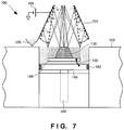
- FIG. 7 is a partially enlarged view showing the arrangement of an anti-deposition cover of a three-dimensional laminating and shaping apparatus according to the third embodiment of the present invention.
- FIG. 8A is a partially enlarged view showing the arrangement of an anti-deposition cover of a three-dimensional laminating and shaping apparatus according to the fourth embodiment of the present invention.
- FIG. 8B is a partially enlarged view showing the arrangement of another example of the anti-deposition cover of the three-dimensional laminating and shaping apparatus according to the fourth embodiment of the present invention.
- FIG. 9 is a partially enlarged view showing the arrangement of an anti-deposition cover of a three-dimensional laminating and shaping apparatus according to the fifth embodiment of the present invention.
- the three-dimensional laminating and shaping apparatus 100 is a powder bed type apparatus.
- the three-dimensional laminating and shaping apparatus 100 irradiates a material spread on a shaping surface by a recoater or the like with an electron beam, thereby melting the material, solidifying the material, and completing laminating of one layer of the material.
- the three-dimensional laminating and shaping apparatus 100 moves down a shaping table by a height equivalent to the height of one layer, and spreads (recoats) the material of the next layer by the recoater or the like.
- the three-dimensional laminating and shaping apparatus 100 After spreading the material, the three-dimensional laminating and shaping apparatus 100 irradiates the material with the electron beam, thereby melting the material, solidifying the material, and completing laminating of the material of the next one layer.
- the three-dimensional laminating and shaping apparatus 100 shapes a desired three-dimensional laminated and shaped object by repeating this operation.
- FIG. 4 is a view showing an example of the arrangement of a three-dimensional laminating and shaping apparatus according to the technical premise of the three-dimensional laminating and shaping apparatus according to this embodiment.
- An electron gun 402 is attached to a vacuum vessel 401 , and a shaping frame table (shaping box) 403 having a circular or square section is installed in the vacuum vessel 401 .
- a Z-axis driving mechanism 404 is installed in a lower portion inside the shaping frame table 403 , and capable of driving a powder table 440 in the Z direction by a rack-and-pinion, ball screw, or the like.
- a heat-resistant flexible seal 460 is formed in the gap between the shaping frame table 403 and powder table 440 , thereby giving slidability and sealability by the flexible seal 460 and the inner sliding surface of the shaping frame table 403 .
- a vacuum pump (not shown) evacuates the vacuum vessel 401 and maintains the interior of the vacuum vessel 401 in a vacuum state.
- a shaping plate (base plate) 406 on which a three-dimensional laminated and shaped object 430 is to be shaped is arranged in a state in which it is floated by a metal powder.
- the shaping plate 406 is grounded to the powder table 440 at a GND potential by a GND line 450 .
- the three-dimensional laminated and shaped object 430 is shaped on the shaping plate 406 .
- a linear funnel (recoater) 405 filled with a metal powder spreads the metal powder to almost the same height as that of the upper surface of the shaping frame table 403 (a spread powder 452 ).
- a hopper (not shown) appropriately replenishes the metal powder to the linear funnel 405 .
- the three-dimensional laminated and shaped object 430 is constructed by two-dimensionally melting the spread (unsintered) powder 452 in a one-layer region of the three-dimensional laminated and shaped object 430 by an electron beam from the electron gun 402 , and overlaying the layers.
- a region of the powder 452 spread on the shaping plate 406 except for the three-dimensional laminated and shaped object 430 is a powder (spread (calcined) powder) 451 calcined by the electron beam from the electron gun 402 , and has conductivity.
- An anti-deposition cover 407 is attached between the shaping surface and electron gun 402 , and prevents deposition of a metal vapor generated during shaping and deposition of metal sputtering by fireworks to the inner walls of the vacuum vessel 401 .
- the upper surface of the shaping plate 406 covered with the metal powder in three directions is set at almost the same height as that of the upper surface of the shaping frame table 403 , and a region slightly narrower than the whole region of the upper surface of the shaping plate 406 is irradiated with the electron beam from the electron gun 402 , thereby preheating the region to a temperature at which the metal powder is calcined.
- the Z-axis driving mechanism 404 slightly moves down the powder table 440 such that the upper surface of the shaping plate 406 is arranged in a position slightly lower than the upper surface of the shaping frame table 403 .
- ⁇ Z as this slight lowering is equivalent to the layer thickness in the Z direction after that.
- the linear funnel 405 filled with the metal powder is moved to the opposite side along the upper surface of the shaping plate 406 , and the region of ⁇ Z slightly narrower than the shaping plate 406 is irradiated with the electron beam from the electron gun 402 , thereby heating the irradiated region, and reliably calcining the metal powder in the irradiated region.
- this two-dimensional region is melted by the electron beam from the electron gun 402 .
- the region slightly narrower than the shaping plate 406 is irradiated with the electron beam from the electron gun 402 again, thereby heating the irradiated region, and preparing for spreading of the powder.
- the electron beam is turned off, the Z-axis driving mechanism 404 moves down the powder table 440 by ⁇ Z, and the linear funnel 405 is moved to the opposite side along the upper surface of the shaping frame table 403 again. Then, the metal powder is spread on the preceding layer by ⁇ Z and reliably calcined by the electron beam from the electron gun 402 , and a two-dimensional-shape region corresponding to the layer is melted.
- the three-dimensional laminated and shaped object 430 is shaped by repeating this process.
- FIG. 5 is a view for explaining a mechanism of generating a smoke phenomenon by the three-dimensional laminating and shaping apparatus according to the technical premise of the three-dimensional laminating and shaping apparatus according to this embodiment.
- FIG. 5 is an enlarged view of a portion below the electron gun 402 shown in FIG. 4 .
- FIG. 5 when the electron beam is emitted for calcination or melting, a large amount of backscattered electrons and secondary electrons are generated from the irradiation position.
- the backscattered electrons collide against the inner walls of the anti-deposition cover 407 above the irradiation position, thereby further emitting backscattered electrons and secondary electrons.
- FIG. 1 is a view showing the arrangement of the three-dimensional laminating and shaping apparatus according to this embodiment.
- FIG. 2 is a partially enlarged view showing the arrangement of the three-dimensional laminating and shaping apparatus according to this embodiment.
- the three-dimensional laminating and shaping apparatus 100 includes a vacuum vessel 101 , an electron gun 102 , a shaping frame table 103 , a Z-axis driving mechanism 104 , a linear funnel 105 , a shaping plate 106 , an anti-deposition cover 107 , and a DC power supply 108 . Note that the three-dimensional laminating and shaping apparatus 100 will be explained below by taking a powder bed type shaping apparatus as an example.
- the anti-deposition cover 107 is a metal cover, attached to the distal end portion of the electron gun 102 , and electrically floated by an insulator 171 .
- the positive DC power supply 108 is externally connected to the anti-deposition cover 107 , and applies a voltage of +30 [V] or more, preferably, a voltage of +50 to +100 [V] to the anti-deposition cover 107 . It is also possible to set the anti-deposition cover 107 at a GND potential, instead of applying the positive voltage.
- the DC power supply 108 is arranged in the vacuum vessel 101 .
- typical examples of the material of the anti-deposition cover 107 are a metal such as titanium (Ti), a titanium-based compound, and an alloy such as stainless steel.
- the material is not limited to them as long as the material emits no large amount of secondary electrons.
- the thickness of the anti-deposition cover 107 is about 0.5 mm, but is not limited to this, and may also be smaller or larger than this.
- the upper surface of the shaping plate 106 covered with the metal powder in three directions is set at almost the same height as that of the upper surface of the shaping frame table 103 , thereby covering the metal powder between the shaping plate 106 and shaping frame table 103 .
- the whole region of the upper surface of the shaping plate 106 is irradiated with the electron beam from the electron gun 102 , thereby preheating the shaping plate 106 to a temperature at which the metal powder is completely calcined.
- the Z-axis driving mechanism 104 moves down the shaping table 140 so that the upper surface of the shaping plate 106 is arranged in a position slightly lower than the upper surface of the shaping frame table 103 . ⁇ Z as this slight lowering is equivalent to the layer thickness in the Z direction after that.
- the linear funnel (recoater) 105 as a material recoater filled with the metal powder is moved to the opposite side along the upper surface of the shaping plate 106 , and the metal powder corresponding to ⁇ Z is recoated and spread on and around the shaping plate 106 .
- the metal powder spread on the shaping plate 106 is irradiated with the electron beam from the electron gun 102 , thereby heating the irradiated region, and reliably calcining the metal powder in the irradiated region.
- this two-dimensional-shape region is melted by the electron beam from the electron gun 102 .
- the region slightly narrower than the shaping plate 106 is irradiated with the electron beam from the electron gun 102 again, thereby heating the irradiated region, and preparing for spreading of the metal powder.
- the electron beam is turned off.
- the Z-axis driving mechanism 104 moves down the powder table 140 by ⁇ Z, the linear funnel 105 is moved to the opposite side along the upper surface of the shaping frame table 103 again, and the metal powder is spread on the preceding layer by ⁇ Z. After the newly spread metal powder is irradiated with the electron beam from the electron gun 102 and reliably calcined, a two-dimensional-shape region corresponding to the layer is melted.
- the three-dimensional laminating and shaping apparatus 100 shapes a three-dimensional laminated and shaped object 130 by repeating this process.
- FIG. 3 is a flowchart for explaining the procedure of the three-dimensional laminating and shaping apparatus 100 according to this embodiment.
- the three-dimensional laminating and shaping apparatus 100 acquires shaping data of the three-dimensional laminated and shaped object 130 .
- the three-dimensional laminating and shaping apparatus 100 recoats and spreads the metal powder on the shaping surface. Note that before recoating the metal powder on the shaping surface, the base plate is preheated to a calcination temperature.
- step S 305 the three-dimensional laminating and shaping apparatus 100 applies a predetermined voltage to the anti-deposition cover 107 .
- step S 307 the three-dimensional laminating and shaping apparatus 100 performs calcination by irradiating the recoated metal powder with an electron beam.
- step S 309 the three-dimensional laminating and shaping apparatus 100 performs final melting by irradiating the calcined metal powder with the electron beam.
- step S 311 the three-dimensional laminating and shaping apparatus 100 determines whether shaping of the three-dimensional laminated and shaped object 130 is complete. If the three-dimensional laminating and shaping apparatus 100 determines that shaping of the three-dimensional laminated and shaped object 130 is complete (YES in step S 311 ), the three-dimensional laminating and shaping apparatus 100 terminates the shaping. If the three-dimensional laminating and shaping apparatus 100 determines that shaping is not complete (NO in step S 311 ), the three-dimensional laminating and shaping apparatus 100 repeats the steps from step S 303 .
- a material which generates no large amount of secondary electrons is used, and a positive voltage is applied to the anti-deposition cover. Therefore, the generation of secondary electrons can effectively be suppressed. Also, since the generation of secondary electrons is suppressed, it is possible to suppress charge-up of the metal powder in an unsintered region, and suppress the occurrence of a smoke phenomenon.
- FIG. 6 is a view for explaining the arrangement of an anti-deposition cover of a three-dimensional laminating and shaping apparatus 600 according to this embodiment.
- An anti-deposition cover 607 is arranged perpendicularly to a shaping frame table 103 .
- the anti-deposition cover 607 is moved up to give a passing space to the linear funnel 105 .
- the anti-deposition cover 607 When a new metal powder is spread by the linear funnel 105 by recoating the metal powder of one layer, the anti-deposition cover 607 is moved down to a position where the anti-deposition cover 607 is in contact with the recoated metal powder, and an electron beam is emitted. Consequently, no electron beam arrives at an unsintered portion which is not to be irradiated with the electron beam, so charge-up of the unsintered portion can be suppressed.
- This embodiment can suppress the generation of secondary electrons by using a material which emits no large amount of secondary electrons, and applying a positive voltage to the anti-deposition cover.
- FIG. 7 is a view for explaining the arrangement of an anti-deposition cover of a three-dimensional laminating and shaping apparatus 700 according to this embodiment.
- An anti-deposition cover 707 has a conical shape, and has a large opening near a shaping frame table 103 .
- the anti-deposition cover 707 is movable and leaps up when a liner funnel 105 spreads a metal powder on a shaping surface, and the linear funnel 105 moves in a space between the anti-deposition cover 707 and shaping surface.
- the anti-deposition cover 707 moves down (the dotted lines in FIG. 7 ), so that only a portion above a shaping plate 106 is irradiated with the electron beam.
- This embodiment can suppress the generation of secondary electrons by using a material which emits no large amount of secondary electrons, and applying a positive voltage to the anti-deposition cover.
- FIG. 8A is a view for explaining the arrangement of an anti-deposition cover of a three-dimensional laminating and shaping apparatus 800 according to this embodiment.
- FIG. 8B is a view for explaining the arrangement of another example of the anti-deposition cover of the three-dimensional laminating and shaping apparatus 800 according to this embodiment.
- an anti-deposition cover 807 has a structure including fins 871 inside.
- the material of the fins 871 can be the same as or different from the material of the anti-deposition cover 807 .
- an attachment angle at which the fins 871 are attached to the anti-deposition cover 807 can be either an acute angle or obtuse angle, and can also be an arbitrary angle.
- the surface area of the anti-deposition cover 807 can further be increased by giving a wave-like shape to the anti-deposition cover, and combining the anti-deposition cover 807 with the fins 871 .
- the shape of the anti-deposition cover 807 is not limited to the wave-like shape, and may also be a stepwise shape, zigzag shape, or the like.
- the fins 871 may all have the same length or may have different lengths, and the length of the fin 871 nearest to the shaping surface may be made larger than those of other fins 871 .
- the anti-deposition cover 807 has a GND potential, but it is also possible to apply a positive voltage to the anti-deposition cover 807 as in the abovementioned second embodiment and the like.
- the surface area of the trap mechanism for trapping backscattered electrons and secondary electrons can be increased. Accordingly, it is possible to trap more backscattered electrons and secondary electrons, and suppress the occurrence of a smoke phenomenon.
- FIG. 9 is a view for explaining the arrangement of an anti-deposition cover of the three-dimensional laminating and shaping apparatus 900 according to this embodiment.
- An anti-deposition cover 907 has a GND-potential ground portion 971 inside.
- the ground portion 971 is formed inside the anti-deposition cover 907 , and the electric field from the anti-deposition cover 907 is fixed to the GND level by the ground portion 971 .
- the ground portion 971 is attached to be electrically floated from the anti-deposition cover 907 by an insulator.
- the ground portion is formed, and this makes it possible to trap secondary electrons and backscattered electrons generated from the anti-deposition cover, thereby reducing scattered electrons near a shaping surface. In addition, it is possible to suppress charge-up of a metal powder in an unsintered region, and suppress the occurrence of a smoke phenomenon.
- the present invention is applicable to a system including a plurality of devices or a single apparatus.
- the present invention is also applicable even when an information processing program for implementing the functions of the embodiments is supplied to the system or apparatus directly or from a remote site.
- the present invention also incorporates the program installed in a computer to implement the functions of the present invention by the computer, a medium storing the program, and a WWW (World Wide Web) server that causes a user to download the program.
- the present invention incorporates at least a non-transitory computer readable medium storing a program that causes a computer to execute processing steps included in the above-described embodiments.
Landscapes
- Engineering & Computer Science (AREA)
- Chemical & Material Sciences (AREA)
- Manufacturing & Machinery (AREA)
- Materials Engineering (AREA)
- Mechanical Engineering (AREA)
- Powder Metallurgy (AREA)
Abstract
Description
Claims (7)
Applications Claiming Priority (1)
| Application Number | Priority Date | Filing Date | Title |
|---|---|---|---|
| PCT/JP2016/059644 WO2017163404A1 (en) | 2016-03-25 | 2016-03-25 | 3d additive manufacturing device, control method for 3d additive manufacturing device, and control program for 3d additive manufacturing device |
Publications (2)
| Publication Number | Publication Date |
|---|---|
| US20180147654A1 US20180147654A1 (en) | 2018-05-31 |
| US10583517B2 true US10583517B2 (en) | 2020-03-10 |
Family
ID=59899876
Family Applications (1)
| Application Number | Title | Priority Date | Filing Date |
|---|---|---|---|
| US15/122,836 Expired - Fee Related US10583517B2 (en) | 2016-03-25 | 2016-03-25 | Three-dimensional laminating and shaping apparatus, three-dimensional lamenting and shaping apparatus control method, and three-dimensional laminating and shaping apparatus control program |
Country Status (4)
| Country | Link |
|---|---|
| US (1) | US10583517B2 (en) |
| EP (1) | EP3248717B1 (en) |
| JP (1) | JP6231695B1 (en) |
| WO (1) | WO2017163404A1 (en) |
Families Citing this family (9)
| Publication number | Priority date | Publication date | Assignee | Title |
|---|---|---|---|---|
| US10549346B2 (en) * | 2016-03-30 | 2020-02-04 | Canon Kabushiki Kaisha | Three-dimensional modeling apparatus, three-dimensional model body manufacturing method, and three-dimensional modeling data |
| US11059123B2 (en) | 2017-04-28 | 2021-07-13 | Arcam Ab | Additive manufacturing of three-dimensional articles |
| US10898968B2 (en) * | 2017-04-28 | 2021-01-26 | Divergent Technologies, Inc. | Scatter reduction in additive manufacturing |
| JP7007152B2 (en) | 2017-10-19 | 2022-01-24 | 株式会社アドバンテスト | Three-dimensional laminated modeling equipment and laminated modeling method |
| US11167375B2 (en) | 2018-08-10 | 2021-11-09 | The Research Foundation For The State University Of New York | Additive manufacturing processes and additively manufactured products |
| JP7293588B2 (en) * | 2018-08-27 | 2023-06-20 | 三菱電機株式会社 | LAMINATED MAKING APPARATUS AND LAMINATED MAKING METHOD |
| WO2020059060A1 (en) * | 2018-09-19 | 2020-03-26 | 技術研究組合次世代3D積層造形技術総合開発機構 | Evaluation method for powder for metal additive manufacturing, evaluation program, manufacturing method, information processing device, and metal additive manufacturing device |
| SE544890C2 (en) * | 2020-04-17 | 2022-12-20 | Freemelt Ab | Preheating of powder bed |
| JP7229977B2 (en) * | 2020-09-17 | 2023-02-28 | 日本電子株式会社 | Three-dimensional layered manufacturing apparatus and three-dimensional layered manufacturing method. |
Citations (11)
| Publication number | Priority date | Publication date | Assignee | Title |
|---|---|---|---|---|
| JPH07138741A (en) | 1993-11-17 | 1995-05-30 | Canon Inc | Vacuum vapor deposition device |
| US6326635B1 (en) * | 1999-07-30 | 2001-12-04 | Etec Systems, Inc. | Minimization of electron fogging in electron beam lithography |
| US20040262261A1 (en) * | 2003-06-27 | 2004-12-30 | Fink Jeffrey E. | Methods and systems for creating layer-formed plastic elements with improved properties |
| US20070145269A1 (en) * | 2005-09-30 | 2007-06-28 | Applied Materials, Inc. | Electron anti-fogging baffle used as a detector |
| WO2008147306A1 (en) | 2007-05-15 | 2008-12-04 | Arcam Ab | Method and device for producing three-dimensional objects |
| US20090042050A1 (en) * | 2003-12-05 | 2009-02-12 | Paolo Matteazzi | Method and Apparatus for Sintering of Inorganic Materials as Well as Resulting Objects |
| US20140277671A1 (en) | 2013-03-15 | 2014-09-18 | Marc Andrew Kronenberg | Method and system of manufacturing a golf club, and a manufactured golf club head |
| WO2014170127A1 (en) | 2013-04-18 | 2014-10-23 | Arcam Ab | Method and apparatus for additive manufacturing |
| US20140370323A1 (en) | 2011-12-28 | 2014-12-18 | Arcam Ab | Method and apparatus for increasing the resolution in additively manufactured three-dimensional articles |
| JP2015175012A (en) | 2014-03-13 | 2015-10-05 | 日本電子株式会社 | Three-dimensional lamination molding device and method |
| CN104959724A (en) | 2015-07-15 | 2015-10-07 | 桂林狮达机电技术工程有限公司 | Electron beam rapid forming device characteristic point data collecting device and method |
-
2016
- 2016-03-25 WO PCT/JP2016/059644 patent/WO2017163404A1/en active Application Filing
- 2016-03-25 EP EP16825690.7A patent/EP3248717B1/en active Active
- 2016-03-25 US US15/122,836 patent/US10583517B2/en not_active Expired - Fee Related
- 2016-03-25 JP JP2016547108A patent/JP6231695B1/en not_active Expired - Fee Related
Patent Citations (17)
| Publication number | Priority date | Publication date | Assignee | Title |
|---|---|---|---|---|
| JPH07138741A (en) | 1993-11-17 | 1995-05-30 | Canon Inc | Vacuum vapor deposition device |
| US6326635B1 (en) * | 1999-07-30 | 2001-12-04 | Etec Systems, Inc. | Minimization of electron fogging in electron beam lithography |
| US20040262261A1 (en) * | 2003-06-27 | 2004-12-30 | Fink Jeffrey E. | Methods and systems for creating layer-formed plastic elements with improved properties |
| US20090042050A1 (en) * | 2003-12-05 | 2009-02-12 | Paolo Matteazzi | Method and Apparatus for Sintering of Inorganic Materials as Well as Resulting Objects |
| US20070145269A1 (en) * | 2005-09-30 | 2007-06-28 | Applied Materials, Inc. | Electron anti-fogging baffle used as a detector |
| US9162394B2 (en) | 2007-05-15 | 2015-10-20 | Arcam Ab | Method and device for producing three-dimensional objects |
| JP2010526694A (en) | 2007-05-15 | 2010-08-05 | アルカム アーベー | Method and apparatus for making a three-dimensional object |
| WO2008147306A1 (en) | 2007-05-15 | 2008-12-04 | Arcam Ab | Method and device for producing three-dimensional objects |
| US9162393B2 (en) | 2007-05-15 | 2015-10-20 | Arcam Ab | Method and device for producing three-dimensional objects |
| US20140370323A1 (en) | 2011-12-28 | 2014-12-18 | Arcam Ab | Method and apparatus for increasing the resolution in additively manufactured three-dimensional articles |
| US20140277671A1 (en) | 2013-03-15 | 2014-09-18 | Marc Andrew Kronenberg | Method and system of manufacturing a golf club, and a manufactured golf club head |
| WO2014170127A1 (en) | 2013-04-18 | 2014-10-23 | Arcam Ab | Method and apparatus for additive manufacturing |
| US20170080495A1 (en) | 2013-04-18 | 2017-03-23 | Arcam Ab | Method and apparatus for additive manufacturing |
| US20170080494A1 (en) | 2013-04-18 | 2017-03-23 | Arcam Ab | Method and apparatus for additive manufacturing |
| JP2015175012A (en) | 2014-03-13 | 2015-10-05 | 日本電子株式会社 | Three-dimensional lamination molding device and method |
| US20150306700A1 (en) * | 2014-03-13 | 2015-10-29 | Jeol Ltd. | Machine and Method for Additive Manufacturing |
| CN104959724A (en) | 2015-07-15 | 2015-10-07 | 桂林狮达机电技术工程有限公司 | Electron beam rapid forming device characteristic point data collecting device and method |
Non-Patent Citations (6)
| Title |
|---|
| Espacenet English abstract of CN 104959724 A. |
| International Search Report (ISR) dated Jun. 21, 2016 for International Application No. PCT/JP2016/059644. |
| J-PlatPat English abstract of JP 2015-175012 A. |
| J-PlatPat English abstract of JP 7-138741 A. |
| Supplementary European Search Report (SESR) dated Sep. 21, 2018 in connection with corresponding European Patent Application No. 16 82 5690.7. |
| Written Opinion (WO) dated Jun. 21, 2016 for International Application No. PCT/JP2016/059644. |
Also Published As
| Publication number | Publication date |
|---|---|
| JP6231695B1 (en) | 2017-11-15 |
| EP3248717A1 (en) | 2017-11-29 |
| WO2017163404A1 (en) | 2017-09-28 |
| EP3248717A4 (en) | 2018-10-24 |
| US20180147654A1 (en) | 2018-05-31 |
| EP3248717B1 (en) | 2020-09-02 |
| JPWO2017163404A1 (en) | 2018-03-29 |
Similar Documents
| Publication | Publication Date | Title |
|---|---|---|
| US10583517B2 (en) | Three-dimensional laminating and shaping apparatus, three-dimensional lamenting and shaping apparatus control method, and three-dimensional laminating and shaping apparatus control program | |
| US10610957B2 (en) | Three-dimensional laminating and shaping apparatus, three-dimensional laminating and shaping apparatus control method, and three-dimensional laminating and shaping apparatus control program | |
| RU2496606C2 (en) | Method and device for marking 3d structures | |
| EP2937163B1 (en) | Method for additive manufacturing | |
| WO2019088091A1 (en) | Three-dimensional shaping device and three-dimensional shaping method | |
| JP6919714B2 (en) | 3D modeling device and 3D modeling method | |
| US11554442B2 (en) | Additive manufacturing device and additive manufacturing method | |
| JP6866931B2 (en) | 3D modeling device and 3D modeling method | |
| JP2023115028A (en) | Additive manufacturing device and additive manufacturing method | |
| JP2021031756A (en) | Three-dimensional shaping method | |
| US20230150201A1 (en) | Preheating of powder bed |
Legal Events
| Date | Code | Title | Description |
|---|---|---|---|
| AS | Assignment |
Owner name: TECHNOLOGY RESEARCH ASSOCIATION FOR FUTURE ADDITIVE MANUFACTURING, JAPAN Free format text: ASSIGNMENT OF ASSIGNORS INTEREST;ASSIGNORS:KITAMURA, SHINICHI;MANABE, HIRONOBU;REEL/FRAME:039605/0037 Effective date: 20160826 Owner name: TECHNOLOGY RESEARCH ASSOCIATION FOR FUTURE ADDITIV Free format text: ASSIGNMENT OF ASSIGNORS INTEREST;ASSIGNORS:KITAMURA, SHINICHI;MANABE, HIRONOBU;REEL/FRAME:039605/0037 Effective date: 20160826 |
|
| AS | Assignment |
Owner name: TECHNOLOGY RESEARCH ASSOCIATION FOR FUTURE ADDITIVE MANUFACTURING, JAPAN Free format text: ASSIGNMENT OF ASSIGNORS INTEREST;ASSIGNORS:KITAMURA, SHINICHI;MANABE, HIRONOBU;REEL/FRAME:040366/0214 Effective date: 20160926 Owner name: TECHNOLOGY RESEARCH ASSOCIATION FOR FUTURE ADDITIV Free format text: ASSIGNMENT OF ASSIGNORS INTEREST;ASSIGNORS:KITAMURA, SHINICHI;MANABE, HIRONOBU;REEL/FRAME:040366/0214 Effective date: 20160926 |
|
| STPP | Information on status: patent application and granting procedure in general |
Free format text: NON FINAL ACTION MAILED |
|
| STPP | Information on status: patent application and granting procedure in general |
Free format text: RESPONSE TO NON-FINAL OFFICE ACTION ENTERED AND FORWARDED TO EXAMINER |
|
| STPP | Information on status: patent application and granting procedure in general |
Free format text: FINAL REJECTION MAILED |
|
| STPP | Information on status: patent application and granting procedure in general |
Free format text: NOTICE OF ALLOWANCE MAILED -- APPLICATION RECEIVED IN OFFICE OF PUBLICATIONS |
|
| ZAAA | Notice of allowance and fees due |
Free format text: ORIGINAL CODE: NOA |
|
| ZAAB | Notice of allowance mailed |
Free format text: ORIGINAL CODE: MN/=. |
|
| STPP | Information on status: patent application and granting procedure in general |
Free format text: PUBLICATIONS -- ISSUE FEE PAYMENT RECEIVED |
|
| STCF | Information on status: patent grant |
Free format text: PATENTED CASE |
|
| CC | Certificate of correction | ||
| FEPP | Fee payment procedure |
Free format text: MAINTENANCE FEE REMINDER MAILED (ORIGINAL EVENT CODE: REM.); ENTITY STATUS OF PATENT OWNER: LARGE ENTITY |
|
| LAPS | Lapse for failure to pay maintenance fees |
Free format text: PATENT EXPIRED FOR FAILURE TO PAY MAINTENANCE FEES (ORIGINAL EVENT CODE: EXP.); ENTITY STATUS OF PATENT OWNER: LARGE ENTITY |
|
| STCH | Information on status: patent discontinuation |
Free format text: PATENT EXPIRED DUE TO NONPAYMENT OF MAINTENANCE FEES UNDER 37 CFR 1.362 |
|
| FP | Lapsed due to failure to pay maintenance fee |
Effective date: 20240310 |