US10582891B2 - System and methods for monitoring physical therapy and rehabilitation of joints - Google Patents
System and methods for monitoring physical therapy and rehabilitation of joints Download PDFInfo
- Publication number
- US10582891B2 US10582891B2 US15/422,299 US201715422299A US10582891B2 US 10582891 B2 US10582891 B2 US 10582891B2 US 201715422299 A US201715422299 A US 201715422299A US 10582891 B2 US10582891 B2 US 10582891B2
- Authority
- US
- United States
- Prior art keywords
- patient
- sensor unit
- pivot point
- sensor
- point distance
- Prior art date
- Legal status (The legal status is an assumption and is not a legal conclusion. Google has not performed a legal analysis and makes no representation as to the accuracy of the status listed.)
- Active
Links
- 238000012544 monitoring process Methods 0.000 title claims abstract description 27
- 238000000554 physical therapy Methods 0.000 title abstract description 23
- 238000000034 method Methods 0.000 title description 65
- 238000005259 measurement Methods 0.000 claims abstract description 43
- 238000004891 communication Methods 0.000 claims description 51
- 210000003127 knee Anatomy 0.000 claims description 35
- 239000000853 adhesive Substances 0.000 claims description 28
- 230000001070 adhesive effect Effects 0.000 claims description 28
- 230000009471 action Effects 0.000 claims description 24
- 210000002414 leg Anatomy 0.000 claims description 19
- 210000000689 upper leg Anatomy 0.000 claims description 14
- 238000007670 refining Methods 0.000 claims description 3
- 210000003484 anatomy Anatomy 0.000 abstract description 2
- 230000000399 orthopedic effect Effects 0.000 description 26
- 239000007943 implant Substances 0.000 description 22
- 238000003860 storage Methods 0.000 description 19
- 230000000694 effects Effects 0.000 description 18
- 238000001356 surgical procedure Methods 0.000 description 17
- 238000010586 diagram Methods 0.000 description 16
- 210000001519 tissue Anatomy 0.000 description 12
- 239000000463 material Substances 0.000 description 11
- 210000003423 ankle Anatomy 0.000 description 9
- 210000001624 hip Anatomy 0.000 description 9
- 210000002303 tibia Anatomy 0.000 description 9
- XLYOFNOQVPJJNP-UHFFFAOYSA-N water Substances O XLYOFNOQVPJJNP-UHFFFAOYSA-N 0.000 description 9
- 238000004458 analytical method Methods 0.000 description 8
- 230000005021 gait Effects 0.000 description 7
- 210000001503 joint Anatomy 0.000 description 7
- 230000008569 process Effects 0.000 description 7
- 230000035939 shock Effects 0.000 description 7
- 230000008859 change Effects 0.000 description 6
- 230000003287 optical effect Effects 0.000 description 6
- 239000000758 substrate Substances 0.000 description 6
- 210000002435 tendon Anatomy 0.000 description 6
- 238000004364 calculation method Methods 0.000 description 5
- 230000036407 pain Effects 0.000 description 5
- 239000003826 tablet Substances 0.000 description 5
- 238000002560 therapeutic procedure Methods 0.000 description 5
- 238000009529 body temperature measurement Methods 0.000 description 4
- 239000003990 capacitor Substances 0.000 description 4
- 238000004590 computer program Methods 0.000 description 4
- 230000001939 inductive effect Effects 0.000 description 4
- 210000004243 sweat Anatomy 0.000 description 4
- 238000012360 testing method Methods 0.000 description 4
- 238000002604 ultrasonography Methods 0.000 description 4
- 230000001133 acceleration Effects 0.000 description 3
- 238000001514 detection method Methods 0.000 description 3
- 238000005516 engineering process Methods 0.000 description 3
- 239000000835 fiber Substances 0.000 description 3
- 239000012530 fluid Substances 0.000 description 3
- 230000006870 function Effects 0.000 description 3
- 239000002245 particle Substances 0.000 description 3
- 229920003023 plastic Polymers 0.000 description 3
- 239000004033 plastic Substances 0.000 description 3
- 229920001296 polysiloxane Polymers 0.000 description 3
- 239000013598 vector Substances 0.000 description 3
- 210000000707 wrist Anatomy 0.000 description 3
- 206010061218 Inflammation Diseases 0.000 description 2
- 206010023204 Joint dislocation Diseases 0.000 description 2
- 235000014676 Phragmites communis Nutrition 0.000 description 2
- 230000002411 adverse Effects 0.000 description 2
- 238000009207 exercise therapy Methods 0.000 description 2
- 210000003414 extremity Anatomy 0.000 description 2
- 230000035876 healing Effects 0.000 description 2
- 230000006872 improvement Effects 0.000 description 2
- 230000004054 inflammatory process Effects 0.000 description 2
- 210000003041 ligament Anatomy 0.000 description 2
- 230000005055 memory storage Effects 0.000 description 2
- 210000003205 muscle Anatomy 0.000 description 2
- 229920002635 polyurethane Polymers 0.000 description 2
- 239000004814 polyurethane Substances 0.000 description 2
- 238000012545 processing Methods 0.000 description 2
- 238000013139 quantization Methods 0.000 description 2
- 238000011084 recovery Methods 0.000 description 2
- 206010039722 scoliosis Diseases 0.000 description 2
- 210000002832 shoulder Anatomy 0.000 description 2
- 230000008961 swelling Effects 0.000 description 2
- 238000011282 treatment Methods 0.000 description 2
- 206010002091 Anaesthesia Diseases 0.000 description 1
- 206010017577 Gait disturbance Diseases 0.000 description 1
- 206010023230 Joint stiffness Diseases 0.000 description 1
- 244000089486 Phragmites australis subsp australis Species 0.000 description 1
- 206010040829 Skin discolouration Diseases 0.000 description 1
- 206010040880 Skin irritation Diseases 0.000 description 1
- 208000027418 Wounds and injury Diseases 0.000 description 1
- 230000005856 abnormality Effects 0.000 description 1
- 230000004913 activation Effects 0.000 description 1
- 230000037005 anaesthesia Effects 0.000 description 1
- 210000000544 articulatio talocruralis Anatomy 0.000 description 1
- 238000005452 bending Methods 0.000 description 1
- 230000008901 benefit Effects 0.000 description 1
- 210000000746 body region Anatomy 0.000 description 1
- 210000000988 bone and bone Anatomy 0.000 description 1
- 210000001217 buttock Anatomy 0.000 description 1
- 230000010267 cellular communication Effects 0.000 description 1
- 230000001413 cellular effect Effects 0.000 description 1
- 230000000052 comparative effect Effects 0.000 description 1
- 230000006835 compression Effects 0.000 description 1
- 238000007906 compression Methods 0.000 description 1
- 238000012790 confirmation Methods 0.000 description 1
- 238000012937 correction Methods 0.000 description 1
- 230000002596 correlated effect Effects 0.000 description 1
- 230000000875 corresponding effect Effects 0.000 description 1
- 230000008878 coupling Effects 0.000 description 1
- 238000010168 coupling process Methods 0.000 description 1
- 238000005859 coupling reaction Methods 0.000 description 1
- 230000006378 damage Effects 0.000 description 1
- 238000001804 debridement Methods 0.000 description 1
- 230000007547 defect Effects 0.000 description 1
- 230000007812 deficiency Effects 0.000 description 1
- 230000002939 deleterious effect Effects 0.000 description 1
- 210000002310 elbow joint Anatomy 0.000 description 1
- 238000011156 evaluation Methods 0.000 description 1
- 210000003811 finger Anatomy 0.000 description 1
- 210000001145 finger joint Anatomy 0.000 description 1
- 229920002457 flexible plastic Polymers 0.000 description 1
- 210000002683 foot Anatomy 0.000 description 1
- -1 for example Substances 0.000 description 1
- 230000005484 gravity Effects 0.000 description 1
- 238000003306 harvesting Methods 0.000 description 1
- 230000036541 health Effects 0.000 description 1
- 210000004394 hip joint Anatomy 0.000 description 1
- 238000005304 joining Methods 0.000 description 1
- 238000013150 knee replacement Methods 0.000 description 1
- 238000010801 machine learning Methods 0.000 description 1
- 238000012423 maintenance Methods 0.000 description 1
- 238000004519 manufacturing process Methods 0.000 description 1
- 230000007246 mechanism Effects 0.000 description 1
- 239000002184 metal Substances 0.000 description 1
- 230000000474 nursing effect Effects 0.000 description 1
- 230000000737 periodic effect Effects 0.000 description 1
- 230000002035 prolonged effect Effects 0.000 description 1
- 230000004044 response Effects 0.000 description 1
- 238000005096 rolling process Methods 0.000 description 1
- 238000007788 roughening Methods 0.000 description 1
- 230000000276 sedentary effect Effects 0.000 description 1
- 210000000323 shoulder joint Anatomy 0.000 description 1
- 230000037370 skin discoloration Effects 0.000 description 1
- 230000036556 skin irritation Effects 0.000 description 1
- 231100000475 skin irritation Toxicity 0.000 description 1
- 210000004872 soft tissue Anatomy 0.000 description 1
- 238000011477 surgical intervention Methods 0.000 description 1
- 239000004753 textile Substances 0.000 description 1
- 210000003813 thumb Anatomy 0.000 description 1
- 210000001226 toe joint Anatomy 0.000 description 1
- 238000012549 training Methods 0.000 description 1
- 230000007723 transport mechanism Effects 0.000 description 1
- 230000003442 weekly effect Effects 0.000 description 1
- 210000003857 wrist joint Anatomy 0.000 description 1
Images


Classifications
-
- A—HUMAN NECESSITIES
- A61—MEDICAL OR VETERINARY SCIENCE; HYGIENE
- A61B—DIAGNOSIS; SURGERY; IDENTIFICATION
- A61B5/00—Measuring for diagnostic purposes; Identification of persons
- A61B5/48—Other medical applications
- A61B5/4851—Prosthesis assessment or monitoring
-
- A—HUMAN NECESSITIES
- A61—MEDICAL OR VETERINARY SCIENCE; HYGIENE
- A61B—DIAGNOSIS; SURGERY; IDENTIFICATION
- A61B1/00—Instruments for performing medical examinations of the interior of cavities or tubes of the body by visual or photographical inspection, e.g. endoscopes; Illuminating arrangements therefor
- A61B1/04—Instruments for performing medical examinations of the interior of cavities or tubes of the body by visual or photographical inspection, e.g. endoscopes; Illuminating arrangements therefor combined with photographic or television appliances
- A61B1/041—Capsule endoscopes for imaging
-
- A—HUMAN NECESSITIES
- A61—MEDICAL OR VETERINARY SCIENCE; HYGIENE
- A61B—DIAGNOSIS; SURGERY; IDENTIFICATION
- A61B5/00—Measuring for diagnostic purposes; Identification of persons
- A61B5/0002—Remote monitoring of patients using telemetry, e.g. transmission of vital signals via a communication network
- A61B5/0004—Remote monitoring of patients using telemetry, e.g. transmission of vital signals via a communication network characterised by the type of physiological signal transmitted
- A61B5/0013—Medical image data
-
- A—HUMAN NECESSITIES
- A61—MEDICAL OR VETERINARY SCIENCE; HYGIENE
- A61B—DIAGNOSIS; SURGERY; IDENTIFICATION
- A61B5/00—Measuring for diagnostic purposes; Identification of persons
- A61B5/0002—Remote monitoring of patients using telemetry, e.g. transmission of vital signals via a communication network
- A61B5/0015—Remote monitoring of patients using telemetry, e.g. transmission of vital signals via a communication network characterised by features of the telemetry system
- A61B5/002—Monitoring the patient using a local or closed circuit, e.g. in a room or building
-
- A—HUMAN NECESSITIES
- A61—MEDICAL OR VETERINARY SCIENCE; HYGIENE
- A61B—DIAGNOSIS; SURGERY; IDENTIFICATION
- A61B5/00—Measuring for diagnostic purposes; Identification of persons
- A61B5/0002—Remote monitoring of patients using telemetry, e.g. transmission of vital signals via a communication network
- A61B5/0015—Remote monitoring of patients using telemetry, e.g. transmission of vital signals via a communication network characterised by features of the telemetry system
- A61B5/0022—Monitoring a patient using a global network, e.g. telephone networks, internet
-
- A—HUMAN NECESSITIES
- A61—MEDICAL OR VETERINARY SCIENCE; HYGIENE
- A61B—DIAGNOSIS; SURGERY; IDENTIFICATION
- A61B5/00—Measuring for diagnostic purposes; Identification of persons
- A61B5/0002—Remote monitoring of patients using telemetry, e.g. transmission of vital signals via a communication network
- A61B5/0031—Implanted circuitry
-
- A—HUMAN NECESSITIES
- A61—MEDICAL OR VETERINARY SCIENCE; HYGIENE
- A61B—DIAGNOSIS; SURGERY; IDENTIFICATION
- A61B5/00—Measuring for diagnostic purposes; Identification of persons
- A61B5/0033—Features or image-related aspects of imaging apparatus classified in A61B5/00, e.g. for MRI, optical tomography or impedance tomography apparatus; arrangements of imaging apparatus in a room
- A61B5/0035—Features or image-related aspects of imaging apparatus classified in A61B5/00, e.g. for MRI, optical tomography or impedance tomography apparatus; arrangements of imaging apparatus in a room adapted for acquisition of images from more than one imaging mode, e.g. combining MRI and optical tomography
-
- A—HUMAN NECESSITIES
- A61—MEDICAL OR VETERINARY SCIENCE; HYGIENE
- A61B—DIAGNOSIS; SURGERY; IDENTIFICATION
- A61B5/00—Measuring for diagnostic purposes; Identification of persons
- A61B5/0059—Measuring for diagnostic purposes; Identification of persons using light, e.g. diagnosis by transillumination, diascopy, fluorescence
- A61B5/0082—Measuring for diagnostic purposes; Identification of persons using light, e.g. diagnosis by transillumination, diascopy, fluorescence adapted for particular medical purposes
- A61B5/0084—Measuring for diagnostic purposes; Identification of persons using light, e.g. diagnosis by transillumination, diascopy, fluorescence adapted for particular medical purposes for introduction into the body, e.g. by catheters
- A61B5/0086—Measuring for diagnostic purposes; Identification of persons using light, e.g. diagnosis by transillumination, diascopy, fluorescence adapted for particular medical purposes for introduction into the body, e.g. by catheters using infrared radiation
-
- A—HUMAN NECESSITIES
- A61—MEDICAL OR VETERINARY SCIENCE; HYGIENE
- A61B—DIAGNOSIS; SURGERY; IDENTIFICATION
- A61B5/00—Measuring for diagnostic purposes; Identification of persons
- A61B5/01—Measuring temperature of body parts ; Diagnostic temperature sensing, e.g. for malignant or inflamed tissue
-
- A—HUMAN NECESSITIES
- A61—MEDICAL OR VETERINARY SCIENCE; HYGIENE
- A61B—DIAGNOSIS; SURGERY; IDENTIFICATION
- A61B5/00—Measuring for diagnostic purposes; Identification of persons
- A61B5/02—Detecting, measuring or recording pulse, heart rate, blood pressure or blood flow; Combined pulse/heart-rate/blood pressure determination; Evaluating a cardiovascular condition not otherwise provided for, e.g. using combinations of techniques provided for in this group with electrocardiography or electroauscultation; Heart catheters for measuring blood pressure
- A61B5/024—Detecting, measuring or recording pulse rate or heart rate
-
- A—HUMAN NECESSITIES
- A61—MEDICAL OR VETERINARY SCIENCE; HYGIENE
- A61B—DIAGNOSIS; SURGERY; IDENTIFICATION
- A61B5/00—Measuring for diagnostic purposes; Identification of persons
- A61B5/07—Endoradiosondes
- A61B5/076—Permanent implantations
-
- A—HUMAN NECESSITIES
- A61—MEDICAL OR VETERINARY SCIENCE; HYGIENE
- A61B—DIAGNOSIS; SURGERY; IDENTIFICATION
- A61B5/00—Measuring for diagnostic purposes; Identification of persons
- A61B5/103—Detecting, measuring or recording devices for testing the shape, pattern, colour, size or movement of the body or parts thereof, for diagnostic purposes
- A61B5/107—Measuring physical dimensions, e.g. size of the entire body or parts thereof
- A61B5/1071—Measuring physical dimensions, e.g. size of the entire body or parts thereof measuring angles, e.g. using goniometers
-
- A—HUMAN NECESSITIES
- A61—MEDICAL OR VETERINARY SCIENCE; HYGIENE
- A61B—DIAGNOSIS; SURGERY; IDENTIFICATION
- A61B5/00—Measuring for diagnostic purposes; Identification of persons
- A61B5/103—Detecting, measuring or recording devices for testing the shape, pattern, colour, size or movement of the body or parts thereof, for diagnostic purposes
- A61B5/11—Measuring movement of the entire body or parts thereof, e.g. head or hand tremor, mobility of a limb
- A61B5/112—Gait analysis
-
- A—HUMAN NECESSITIES
- A61—MEDICAL OR VETERINARY SCIENCE; HYGIENE
- A61B—DIAGNOSIS; SURGERY; IDENTIFICATION
- A61B5/00—Measuring for diagnostic purposes; Identification of persons
- A61B5/103—Detecting, measuring or recording devices for testing the shape, pattern, colour, size or movement of the body or parts thereof, for diagnostic purposes
- A61B5/11—Measuring movement of the entire body or parts thereof, e.g. head or hand tremor, mobility of a limb
- A61B5/1121—Determining geometric values, e.g. centre of rotation or angular range of movement
-
- A—HUMAN NECESSITIES
- A61—MEDICAL OR VETERINARY SCIENCE; HYGIENE
- A61B—DIAGNOSIS; SURGERY; IDENTIFICATION
- A61B5/00—Measuring for diagnostic purposes; Identification of persons
- A61B5/103—Detecting, measuring or recording devices for testing the shape, pattern, colour, size or movement of the body or parts thereof, for diagnostic purposes
- A61B5/11—Measuring movement of the entire body or parts thereof, e.g. head or hand tremor, mobility of a limb
- A61B5/1126—Measuring movement of the entire body or parts thereof, e.g. head or hand tremor, mobility of a limb using a particular sensing technique
-
- A—HUMAN NECESSITIES
- A61—MEDICAL OR VETERINARY SCIENCE; HYGIENE
- A61B—DIAGNOSIS; SURGERY; IDENTIFICATION
- A61B5/00—Measuring for diagnostic purposes; Identification of persons
- A61B5/45—For evaluating or diagnosing the musculoskeletal system or teeth
- A61B5/4528—Joints
-
- A—HUMAN NECESSITIES
- A61—MEDICAL OR VETERINARY SCIENCE; HYGIENE
- A61B—DIAGNOSIS; SURGERY; IDENTIFICATION
- A61B5/00—Measuring for diagnostic purposes; Identification of persons
- A61B5/45—For evaluating or diagnosing the musculoskeletal system or teeth
- A61B5/4538—Evaluating a particular part of the muscoloskeletal system or a particular medical condition
- A61B5/4585—Evaluating the knee
-
- A—HUMAN NECESSITIES
- A61—MEDICAL OR VETERINARY SCIENCE; HYGIENE
- A61B—DIAGNOSIS; SURGERY; IDENTIFICATION
- A61B5/00—Measuring for diagnostic purposes; Identification of persons
- A61B5/48—Other medical applications
- A61B5/4848—Monitoring or testing the effects of treatment, e.g. of medication
-
- A—HUMAN NECESSITIES
- A61—MEDICAL OR VETERINARY SCIENCE; HYGIENE
- A61B—DIAGNOSIS; SURGERY; IDENTIFICATION
- A61B5/00—Measuring for diagnostic purposes; Identification of persons
- A61B5/68—Arrangements of detecting, measuring or recording means, e.g. sensors, in relation to patient
- A61B5/6801—Arrangements of detecting, measuring or recording means, e.g. sensors, in relation to patient specially adapted to be attached to or worn on the body surface
- A61B5/683—Means for maintaining contact with the body
- A61B5/6832—Means for maintaining contact with the body using adhesives
- A61B5/6833—Adhesive patches
-
- A—HUMAN NECESSITIES
- A61—MEDICAL OR VETERINARY SCIENCE; HYGIENE
- A61B—DIAGNOSIS; SURGERY; IDENTIFICATION
- A61B5/00—Measuring for diagnostic purposes; Identification of persons
- A61B5/68—Arrangements of detecting, measuring or recording means, e.g. sensors, in relation to patient
- A61B5/6846—Arrangements of detecting, measuring or recording means, e.g. sensors, in relation to patient specially adapted to be brought in contact with an internal body part, i.e. invasive
- A61B5/6847—Arrangements of detecting, measuring or recording means, e.g. sensors, in relation to patient specially adapted to be brought in contact with an internal body part, i.e. invasive mounted on an invasive device
- A61B5/686—Permanently implanted devices, e.g. pacemakers, other stimulators, biochips
-
- A—HUMAN NECESSITIES
- A61—MEDICAL OR VETERINARY SCIENCE; HYGIENE
- A61B—DIAGNOSIS; SURGERY; IDENTIFICATION
- A61B5/00—Measuring for diagnostic purposes; Identification of persons
- A61B5/68—Arrangements of detecting, measuring or recording means, e.g. sensors, in relation to patient
- A61B5/6846—Arrangements of detecting, measuring or recording means, e.g. sensors, in relation to patient specially adapted to be brought in contact with an internal body part, i.e. invasive
- A61B5/6867—Arrangements of detecting, measuring or recording means, e.g. sensors, in relation to patient specially adapted to be brought in contact with an internal body part, i.e. invasive specially adapted to be attached or implanted in a specific body part
- A61B5/6878—Bone
-
- A—HUMAN NECESSITIES
- A61—MEDICAL OR VETERINARY SCIENCE; HYGIENE
- A61B—DIAGNOSIS; SURGERY; IDENTIFICATION
- A61B5/00—Measuring for diagnostic purposes; Identification of persons
- A61B5/74—Details of notification to user or communication with user or patient ; user input means
- A61B5/742—Details of notification to user or communication with user or patient ; user input means using visual displays
-
- G—PHYSICS
- G01—MEASURING; TESTING
- G01C—MEASURING DISTANCES, LEVELS OR BEARINGS; SURVEYING; NAVIGATION; GYROSCOPIC INSTRUMENTS; PHOTOGRAMMETRY OR VIDEOGRAMMETRY
- G01C22/00—Measuring distance traversed on the ground by vehicles, persons, animals or other moving solid bodies, e.g. using odometers, using pedometers
- G01C22/006—Pedometers
-
- A—HUMAN NECESSITIES
- A61—MEDICAL OR VETERINARY SCIENCE; HYGIENE
- A61B—DIAGNOSIS; SURGERY; IDENTIFICATION
- A61B90/00—Instruments, implements or accessories specially adapted for surgery or diagnosis and not covered by any of the groups A61B1/00 - A61B50/00, e.g. for luxation treatment or for protecting wound edges
- A61B90/30—Devices for illuminating a surgical field, the devices having an interrelation with other surgical devices or with a surgical procedure
- A61B2090/309—Devices for illuminating a surgical field, the devices having an interrelation with other surgical devices or with a surgical procedure using white LEDs
-
- A—HUMAN NECESSITIES
- A61—MEDICAL OR VETERINARY SCIENCE; HYGIENE
- A61B—DIAGNOSIS; SURGERY; IDENTIFICATION
- A61B2505/00—Evaluating, monitoring or diagnosing in the context of a particular type of medical care
- A61B2505/09—Rehabilitation or training
-
- A—HUMAN NECESSITIES
- A61—MEDICAL OR VETERINARY SCIENCE; HYGIENE
- A61B—DIAGNOSIS; SURGERY; IDENTIFICATION
- A61B2560/00—Constructional details of operational features of apparatus; Accessories for medical measuring apparatus
- A61B2560/02—Operational features
- A61B2560/0204—Operational features of power management
- A61B2560/0214—Operational features of power management of power generation or supply
-
- A—HUMAN NECESSITIES
- A61—MEDICAL OR VETERINARY SCIENCE; HYGIENE
- A61B—DIAGNOSIS; SURGERY; IDENTIFICATION
- A61B2562/00—Details of sensors; Constructional details of sensor housings or probes; Accessories for sensors
- A61B2562/02—Details of sensors specially adapted for in-vivo measurements
- A61B2562/0219—Inertial sensors, e.g. accelerometers, gyroscopes, tilt switches
-
- A—HUMAN NECESSITIES
- A61—MEDICAL OR VETERINARY SCIENCE; HYGIENE
- A61B—DIAGNOSIS; SURGERY; IDENTIFICATION
- A61B2562/00—Details of sensors; Constructional details of sensor housings or probes; Accessories for sensors
- A61B2562/02—Details of sensors specially adapted for in-vivo measurements
- A61B2562/0223—Magnetic field sensors
-
- A—HUMAN NECESSITIES
- A61—MEDICAL OR VETERINARY SCIENCE; HYGIENE
- A61B—DIAGNOSIS; SURGERY; IDENTIFICATION
- A61B2562/00—Details of sensors; Constructional details of sensor housings or probes; Accessories for sensors
- A61B2562/02—Details of sensors specially adapted for in-vivo measurements
- A61B2562/0247—Pressure sensors
Definitions
- the present invention is directed to the area of physical therapy, orthopedic implants, and rehabilitation.
- the present invention is also directed to systems and methods for monitoring physical therapy and rehabilitation of joints.
- Joint replacement surgery is a common orthopedic procedure for joints such as the shoulder, hip, knee, ankle, and wrist. In situations where the patient has worn-out or damaged a joint, it is possible to replace the joint with an implant that can merge with the skeletal structure and restore pain free movement and function.
- a surgeon Prior to implanting prosthetic components in a joint of a patient, a surgeon generally resects at least a portion of the patient's native bone in order to create a platform, recess, or cavity for receiving at least a portion of the prosthetic components being implanted. During the process of implanting the prosthetic components muscles and tendons must be repositioned and reattached.
- the patient must go through physical therapy in order to recover from this major surgery.
- the patient must exercise regularly as well as push for flexibility and balance in muscles that have been displaced. While the goal is to have the patient extend their range of motion, there can be an increased risk of falls or over-extension that can damage the implant and injure the patient. If the patient does not push their rehabilitation and achieve the needed range of motion, they will find themselves with a stiff joint which may require an additional surgical operation (MUA—Manipulation Under Anesthesia) to achieve an adequate range of motion to maintain their active lifestyle. Measuring or monitoring the progress of the physical therapy can be problematic but is very useful for maintaining the patient's dedication and participation.
- One embodiment is a system for monitoring a patient.
- the system includes a sensor unit configured and arranged to be disposed on or within the patient, the sensor unit including an accelerometer and a communication arrangement.
- the system also includes a patient device configured and arranged for communication with the sensor unit.
- the patient device includes a display, a tilt angle sensor, a memory, and a processor coupled to the display and memory.
- the processor is configured and arranged for performing actions including determining a tilt angle of the patient device, when sitting on a thigh of the patient, using the tilt angle sensor of the patient device; obtaining a tilt angle of the sensor unit disposed on or within a portion of a leg of the patient below a knee of the patient; and determining an extension or flexion of the knee of the patient using the tilt angle of the patient device and the tilt angle of the sensor unit.
- obtaining the tilt angle of the sensor unit includes obtaining the tilt angle of the sensor unit that has been determined by the processor of the sensor unit. In at least some embodiments, obtaining the tilt angle of the sensor unit includes obtaining at least one position value of the accelerometer of the sensor unit and calculating the tilt angle from the at least one position value.
- determining the extension or flexion includes determining a maximum flexion of the knee using the tilt angle of the sensor unit at a maximum forward extension of the knee. In at least some embodiments, determining the extension or flexion includes determining a maximum extension of the knee using the tilt angle of the sensor unit at a maximum backward extension of the knee. In at least some embodiments, the actions further include determining an estimated quadricep force using the tilt angle of the sensor unit.
- the system includes at least one sensor unit configured and arranged to be disposed on or within the patient, the at least one sensor unit, in combination, including at least two accelerometers and a communication arrangement.
- the system also includes a patient device configured and arranged for communication with the at least one sensor unit.
- the patient device includes a display, a memory, and a processor coupled to the display and memory.
- the processor is configured and arranged for performing actions including, during performance of an exercise, obtaining a pivot point distance using the at least two accelerometers of the at least one sensor unit; comparing the determined pivot point distance with pre-determined pivot point distances for a plurality of exercises; and, based on the comparison, identifying the exercise being performed as a one of the plurality of exercises.
- obtaining the pivot point distance includes obtaining the pivot point distance that has been determined by the processor of at least one of the at least one sensor unit. In at least some embodiments, obtaining the pivot point distance includes obtaining at least one position value from each of two of the accelerometers and calculating the pivot point distance from the obtained position values. In at least some embodiments, obtaining a pivot point distance includes obtaining an average pivot point distance over a period of time.
- the pre-determined pivot point distances for the plurality of exercises are average pivot point distances for the plurality of exercises for a population of patients. In at least some embodiments, the pre-determined pivot point distances for the plurality of exercises are determined from one or more anatomical measurements of the patient. In at least some embodiments, the actions further including determining a number of repetitions of the exercise being performed.
- Yet another embodiment is a system for monitoring a patient.
- the system includes at least one sensor unit configured and arranged to be disposed on or within the patient, the at least one sensor unit, in combination, including at least two accelerometers and a communication arrangement.
- the system also includes a patient device configured and arranged for communication with the at least one sensor unit.
- the patient device includes a display, a memory, and a processor coupled to the display and memory.
- the processor is configured and arranged for performing actions including a) predicting average pivot point distances for a plurality of exercises; b) during performance of a one of the exercises, obtaining a pivot point distance using the at least two accelerometers of the at least one sensor unit; c) using the predicted average pivot point distances, identifying the exercise being performed; and d) refining the predicted average pivot point distance for the exercise being performed with the obtained pivot point distance.
- the actions further include repeating steps b)-d) for the one of the exercises, using the refined predicted average pivot point distance instead of the predicted average pivot point distance. In at least some embodiments, the actions further include repeating steps b)-d) for an additional one or more of the exercises.
- obtaining the pivot point distance includes obtaining the pivot point distance that has been determined by the processor of at least one of the at least one sensor unit. In at least some embodiments, obtaining the pivot point distance includes obtaining at least one position value from each of two of the accelerometers and calculating the pivot point distance from the obtained position values.
- the actions further include obtaining anatomical information for the patient, wherein predicting average pivot point distances for a plurality of exercises includes predicting the average pivot point distances for the plurality of exercises using the anatomical information.
- the anatomical information includes a height of the patient.
- Yet another embodiment is a method for performing the actions recited for any of the systems described above.
- a further embodiment is a non-transitory computer readable medium comprising instructions for performing the actions recited for any of the systems described above.
- FIG. 1 is a schematic diagram of one embodiment of a system for monitoring rehabilitation of a patient after implant surgery, according to the invention
- FIG. 2 is a schematic diagram of one embodiment of a computing device for use in the system of FIG. 1 , according to the invention
- FIG. 3A is a top view of one embodiment of a sensor module that contains sensors for monitoring rehabilitation of a patient, according to the invention
- FIG. 3B is a bottom view of the sensor module of FIG. 3A , according to the invention.
- FIG. 4A is a perspective side view of another embodiment of a sensor unit and a base disengaged from each other, according to the invention.
- FIG. 4B is a side view of the sensor unit and base of FIG. 4A engaged with each other, according to the invention.
- FIG. 4C is a top view of the sensor unit and base of FIG. 4A engaged with each other, according to the invention.
- FIG. 4D is an exploded view of the sensor unit of FIG. 4A , according to the invention.
- FIG. 4E is an exploded view of one embodiment of a housing of the sensor unit of FIG. 4A , according to the invention.
- FIG. 5A is a diagram of one embodiment of a method for determining a tilt angle of a sensor unit, according to the invention.
- FIG. 5B is a diagram of one embodiment of a method for determining extension and flexion, according to the invention.
- FIG. 5C is a flowchart of one embodiment of a method for determining extension and flexion; according to the invention.
- FIG. 6A is a diagram of one embodiment of a method for determining quadricep force, according to the invention.
- FIG. 6B is a flowchart of one embodiment of a method for determining quadricep force; according to the invention.
- FIG. 7 is a diagram for analyzing gait, according to the invention.
- FIG. 8A is a diagram of one embodiment of a method for determining a pivot point distance, according to the invention.
- FIG. 8B is a graph of pivot point distance over time for four different exercise, according to the invention.
- FIG. 8C is a graph of average pivot point distance for four different exercise, according to the invention.
- FIG. 8D is a flowchart of one embodiment of a method for identifying or classifying exercises using pivot point distance; according to the invention.
- FIG. 8E is a flowchart of one embodiment of a method for refining average pivot point distances for use in the method of FIG. 8D ; according to the invention.
- FIG. 9 is a diagram of one embodiment of a user interface for a mobile device to display information obtained from a sensor unit, according to the invention.
- FIG. 10 is a diagram of one embodiment of a user interface for a mobile device to display a range of motion measurement, according to the invention.
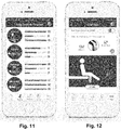
- FIG. 11 is a diagram of one embodiment of a user interface for a mobile device to display a summary of repetitions of exercises, according to the invention.
- FIG. 12 is a diagram of one embodiment of a user interface for a mobile device to display information obtained from a sensor unit, according to the invention.
- FIG. 13 is a diagram of another embodiment of a user interface to display information obtained from a sensor unit, according to the invention.
- FIG. 14 is a diagram of a further embodiment of a user interface to display information obtained from a sensor unit, according to the invention.
- FIG. 15 is a diagram of yet another embodiment of a user interface to display information obtained from a sensor unit, according to the invention.
- the present invention is directed to the area of physical therapy, orthopedic implants, and rehabilitation.
- the present invention is also directed to systems and methods for monitoring physical therapy and rehabilitation of joints.
- a system can be used to monitor physical therapy or the healing process or rehabilitation of the patient after surgery, as well as monitor or verify the extent of the patient's activity.
- the system includes one or more sensors that can communicate with a processor that can produce information, based on the sensor readings and data, that can facilitate the patient or another user, such as a clinician, doctor, physical therapist, nurse, care coordinator, or other appropriate person, monitoring the patient's activity, the status of an orthopedic implant or surrounding tissues, or the effects of rehabilitation or other therapy.
- a clinician, doctor, physical therapist, nurse, care coordinator, or other appropriate person monitoring the patient's activity, the status of an orthopedic implant or surrounding tissues, or the effects of rehabilitation or other therapy.
- the sensors described below, are placed near a physical therapy or rehabilitation site, such as a surgical site or the body portion to be rehabilitated.
- the system may also provide alerts if patient tissue becomes inflamed or if the effectiveness of, or compliance to, physical or rehabilitation therapy is insufficient.
- the system includes a wearable device with one or more sensors.
- one or more sensors may be provided on a wearable device that is applied to the skin of the patient.
- the one or more sensors communicate with a sensor processor on the device containing the sensors.
- the sensor processor or, alternatively or additionally, the sensors, communicate with a processor of a patient device, such as a mobile phone, tablet, computer or the like, or with a processor of a clinician device, such as a mobile phone, tablet, computer or the like.
- FIG. 1 illustrates one embodiment of a system 100 for monitoring an orthopedic implant and rehabilitation after orthopedic replacement surgery.
- the system 100 includes one or more sensors 102 , an optional sensor processor 104 , a patient device 106 (such as a mobile phone, tablet, computer or the like), a clinician device 108 , and a network 60 .
- the one or more sensors 102 and, preferably, the sensor processor 104 are provided in a wearable device 112 that is external to the patient such as, for example, a device that is applied to the skin of the patient or is carried in a brace or other article or textile that is worn by the patient.
- one or more of the sensors 102 and, optionally, the sensor processor can be implanted in the patient.
- one or more of the sensors 102 are implanted and a sensor processor and, optionally, one or more additional sensors are provided in a wearable device.
- the system may include fewer or more components than those illustrated in FIG. 1 , but the system typically includes the sensor(s) 102 and a processor (such as sensor processor 104 , patient device 106 , or clinician device 108 ) to communicate with the sensor(s) and provide information based on the sensor data.
- the wearable device 112 includes the sensors 102 and sensor processor 104 , but it will be understood that other sensors may be included that are not part of the wearable device 112 .
- one or more additional sensors may be combined into another wearable device that may also include a sensor processor.
- the wearable device 102 may not include a sensor processor 104 or the sensor processor 104 may have limited capabilities (such as, for example, obtaining and transmitting sensor readings without (or with limited) analysis of the sensor readings.
- the solid lines indicate communication between components in at least some embodiments of the system. Dotted lines indicate alternative or additional modes of communication between components.
- the sensor processor 104 or sensors 102 may also communicate directly with the clinician device. Communications can include, but is not limited to, wireless communication, wired communication, optical communication, ultrasonic communication, or the combination thereof. Satellite communication, cellular communication, BluetoothTM, near field communications (NFC), Infrared Data Association standard (IrDA), wireless fidelity (WiFi), and worldwide interoperability for microwave access (WiMAX) are non-limiting examples of wireless communication that can be used for communications. Ethernet, digital subscriber line (DSL), fiber to the home (FTTH), and plain old telephone service (POTS) are non-limiting examples of wired communication that can be used for communications.
- DSL digital subscriber line
- FTTH fiber to the home
- POTS plain old telephone service
- the network 60 can be any suitable type of network including, but not limited to, a personal area network (PAN), local area network (LAN), metropolitan area network (MAN), wide area network (WAN), the Internet, or any combination thereof. In at least some embodiments, the network 60 can be bypassed to provide direct connection between components. It will be understood that other devices, such as a server or server farm, memory storage device, or the like can be connected to the patient device 106 or clinician device 108 through the network 60 or directly. For example, a server may be coupled to the patient device 106 or clinician device 108 that stores patient or other medical information, applications, user interfaces, a web interface, or the like for access by the patient device 106 or clinician device 108 .
- PAN personal area network
- LAN local area network
- MAN metropolitan area network
- WAN wide area network
- the Internet or any combination thereof.
- the network 60 can be bypassed to provide direct connection between components.
- other devices such as a server or server farm, memory storage device, or the like can be connected to
- the patient device 106 and the clinician device 108 can be any of a variety of devices, such as computers (for example, a notebook computer, a mobile medical station or computer, a server, a mainframe computer, or a desktop computer), mobile devices (for example, a cellular phone or smartphone, personal digital assistant, or a tablet), or any other suitable device.
- the clinician device 108 can be incorporated into a medical station or system.
- FIG. 2 illustrates one embodiment of a computing device 201 for use as the patient device 106 or clinician device 108 .
- the computing device 201 includes a processor 214 and a memory 216 , a display 218 , and an input device 220 .
- the computing device 201 can be local to the user or can include components that are non-local to the computer including one or both of the processor 214 or memory 216 (or portions thereof). For example, in some embodiments, the user may operate a terminal that is connected to a non-local processor or memory.
- the computing device 201 can utilize any suitable processor 214 including one or more hardware processors that may be local to the user or non-local to the user or other components of the computing device.
- the processor 214 is configured to execute instructions provided to the processor. Such instructions can include any of the steps of methods or processes described herein.
- the memory 216 illustrates a type of computer-readable media, namely computer-readable storage media.
- Computer-readable storage media may include, but is not limited to, nonvolatile, non-transitory, removable, and non-removable computer-readable media implemented in any method or technology for storage of information, such as computer readable instructions, data structures, program modules, or other data. Examples of computer-readable storage media include RAM, ROM, EEPROM, flash memory, or other memory technology, CD-ROM, digital versatile disks (“DVD”) or other optical storage, magnetic cassettes, magnetic tape, magnetic disk storage or other magnetic storage devices, or any other medium which can be used to store the desired information and which can be accessed by a computing device.
- Communication methods provide another type of computer readable media; namely communication media.
- Communication media typically embodies computer-readable instructions, data structures, program modules, or other data in a modulated data signal such as a carrier wave, data signal, or other transport mechanism and include any information delivery media.
- modulated data signal and “carrier-wave signal” includes a signal that has one or more of its characteristics set or changed in such a manner as to encode information, instructions, data, and the like, in the signal.
- communication media includes wired media such as twisted pair, coaxial cable, fiber optics, wave guides, and other wired media and wireless media such as acoustic, RF, infrared, BluetoothTM, near field communication, and other wireless media.
- wired media such as twisted pair, coaxial cable, fiber optics, wave guides, and other wired media
- wireless media such as acoustic, RF, infrared, BluetoothTM, near field communication, and other wireless media.
- the display 218 can be any suitable display device, such as a monitor, screen, display, or the like, and can include a printer.
- the input device 220 can be, for example, a keyboard, mouse, touch screen, track ball, joystick, voice recognition system, camera, microphone, or any combination thereof, or the like.
- the sensor processor 104 can be any suitable processor including one or more hardware processors.
- the sensor processor 104 is configured to execute instructions provided to the processor.
- the sensor processor 104 is configured to receive sensor data from the sensor(s) and communicate with the patient device 106 , network 60 , clinician device 108 , or any combination thereof.
- the sensor processor 104 may also process or analyze the sensor data and may have instructions stored thereon to perform such processing or analysis including, for example, instructions to perform the steps of any of the processing or analysis described herein.
- one or more of the sensor(s) 102 can each include a processor that perhaps some or all of the functions of the sensor processor 104 .
- the one or more sensors 102 are provided to monitor an orthopedic implant and surrounding tissue or monitor rehabilitation after orthopedic surgery whether an implant was required or not, or to provide preparatory therapy in advance of a surgery, or any combination thereof.
- This disclosure will use an orthopedic knee implant as an example, but it will be understood that other joint implants, such as, for example, implants for the shoulder, hip, ankle, wrist, or any other joint, or any other orthopedic device, such as an orthopedic spinal implant, whether joint replacement, joint resurfacing, soft tissue reconstruction, debridement, limb correction surgery, ligament replacement, or the like.
- any suitable type of sensor 102 can be used including, but not limited to, accelerometers, magnetometers, gyroscopes, proximity sensors, infrared sensors, ultrasound sensors, thermistors or other temperature sensors, cameras, piezoelectric or other pressure sensors, sonar sensors, external fluid sensor, skin discoloration sensor, pH sensor, microphone, or the like or any combination thereof.
- the system 100 includes at least one, two, three, four, five, six, or more different types of sensors 102 .
- the system may include at least one, two, three, four, five, six, eight, ten, or more sensors 102 .
- Further examples of suitable sensors and their arrangement and use can be found at U.S. patent application Ser. Nos. 15/077,809 and 15/077,793 and U.S. Provisional Patent Applications Ser. Nos. 62/136,892 and 62/136,925, all of which are incorporated herein by reference.
- the one or more sensors 102 can be used to measure, monitor, or otherwise observe one or more aspects of the orthopedic device, surrounding tissue, or patient activity, or the like.
- a system 100 can observe or measure one or more of these items or any combination of the items.
- One or more sensors may count steps or repetitions of an exercise or number of joint movements or other actions experienced by the sensor, and may be utilized to determine what type of exercise or movement is occurring. This can be used, for example, to monitor patient activity, monitor compliance with exercise therapy, or monitor possible signs of pain or other conditions that may hinder or aid rehabilitation.
- the sensor data may also be used to monitor changes in activity or trends in activity.
- One or more sensors may sense or detect or compute the range of motion of the sensor, joint, or other portion of the patient body or the flexion of the joint. This can be used, for example, to monitor patient rehabilitation, patient activity, monitor compliance with exercise therapy, or monitor possible signs of pain or other conditions that may hinder or aid rehabilitation. These sensors or other sensors may be used to monitor shock to, or impact on, the orthopedic device or tissue around the orthopedic device. The sensor data may also be used to monitor changes in range of motion or flexion or trends in range of motion or flexion.
- two proximity sensors for example, a magnetometer and a magnet—such as a permanent magnet, electromagnet, or polymagnet or the like
- the distance between the two proximity sensors can be detected, measured, or otherwise observed.
- the distance between the two proximity sensors can be correlated to flexion or range of motion of the patient's joint.
- the variation in the distance between the two proximity sensors can be used to measure number of repetitions of joint motion or to monitor compliance with patient therapy.
- the variation in distance among repetitions or the trend in the variation among repetitions may be used to monitor improvement in joint flexibility or may indicate pain or other deleterious physical conditions of orthopedic implant or surrounding tissue. This information can be used to measure progress in the physical therapy following the surgery.
- one or more accelerometers can measure the acceleration from joint movement.
- a ratio of measured acceleration between accelerometers of known distance apart can be used to assess the joint movement and region of motion or flexion by calculating the center of rotation about which the device is being rotated. This information can be used for the same purposes as described in the preceding example.
- an accelerometer and 2) a gyroscope or magnetometer can be used to measure range of motion, rate of motion, number of repetitions, or the like. This information can be used for the same purposes as described in the preceding two examples.
- a single sensor such as an accelerometer, gyroscope, or magnetometer can be used to measure or otherwise observe range of motion, rate of motion, number of repetitions, or the like.
- these measurements or other observations are determined using the sensor data and one or more assumptions about the sensor or sensor data based on, for example, the recognition of patterns in the sensor data, the upper and lower limits of the range in the data collected, or the like. Such information can be used in a manner similar to that in the preceding three examples.
- One or more sensors may sense or detect or compute a temperature or a change in temperature or a temperature trend.
- the temperature may be a skin temperature or ambient temperature.
- the temperature measurements may be used, for example, to indicate the possibility of inflammation or pain or another condition that may hinder rehabilitation or patient health.
- the temperature measurement may also be used, for example, to monitor if icing is being performed effectively, which can help reduce inflammation and aid healing.
- These sensors may also or alternatively be used to sense, detect, or measure a pulse, a change in pulse, trends in the patient's pulse, a pulse profile, or heart rate recovery after patient activity (such as exercise or other exertion).
- One or more sensors can sense or detect or compute particles or density of particles or a particle density trend. These sensors may also be used to sense the tissue surrounding the orthopedic device, detect wear or dimensional changes on the orthopedic device or surrounding tissue, or the like. Ultrasound and sonar sensors may also be used to determine how close other parts of the knee (or other joint) are to the implant.
- One or more sensors can sense or detect or compute pressure or load with or around the sensor or orthopedic device.
- the sensor data may also be used to monitor changes in range of pressure or load bearing or trends in pressure or load bearing.
- These sensors or other sensors may be used to monitor shock to, or impact on, the orthopedic device or tissue around the orthopedic device.
- a pressure or load bearing sensor may also be used to detect swelling of the tissue around the orthopedic implant.
- Multiple pressure or load bearing sensors may also be used to detect flexion (which may be indicated by a uniaxial stretching of the tissue) and swelling (which may be indicated by biaxial stretching of the tissue.)
- Power can be provided to the sensors 102 and optional sensor processor 104 using any suitable power source including, but not limited to, primary cells, rechargeable batteries, storage capacitors, other power storage devices, or the like or any combination thereof.
- the power can be provided by a kinetic energy power source that utilizes the movements of the patient's body to generate power for the components or to or to charge a battery or storage capacitor or other power storage device coupled to the components.
- wireless power sources can be used in place of (or in addition to) the battery, storage capacitor, or other power storage device.
- a charging port can be provided for charging the battery or storage capacitor or other power storage device from a source such as a wall socket.
- a source such as a wall socket.
- wireless charging systems and methods can also be used. It will be understood that in some embodiments there may be multiple methods for providing power to the component or to a power storage device associated with the component. All of the sensors and optional sensor processor may be coupled to the same power source or some of the sensors (or even all of the sensors) and sensor processor may have individual power sources.
- the sensors and optional sensor processor can be active at all times to measure, monitor, or otherwise observe.
- one or more of the sensors and optional sensor processor can be active periodically (with a period of, for example, 15 or 30 seconds or 1, 5, 10, 15, or 30 minutes or 1, 2, 3, 4, 6, 7, or 24 hours) or randomly to measure, monitor, or otherwise observe.
- the period may be programmable.
- the period may be optionally altered based on data from one or more of the sensors.
- one or more of the sensors and optional sensor processor may be activated manually or automatically by the sensor module, patient device, clinician device, or other device.
- the sensors and optional sensor processor may have different activation schedules (continuous, periodic, random, or manual). For example, a sensor to measure temperature may do so periodically, a sensor to measure number of steps or movement of the joint may be continuous, and a sensor to measure range of motion may be activated manually by the wearable device, patient device, or clinician device when the patient performs rehabilitation exercises.
- the systems and methods will be described herein with reference to an orthopedic knee implant or other knee surgery. Similar systems and methods can be used with other joints including, but not limited to, the finger joint, wrist joint, elbow joint, shoulder joint, hip joint, ankle joint, or toe joint.
- the systems and methods can be used to monitor physical therapy for any reason including, but not limited to, rehabilitation associated with other treatments including treatments for ligament or fracture surgery.
- FIGS. 3A and 3B are top and bottom views, respectively, of one embodiment of a sensor unit 358 that can be adhered, or otherwise placed adjacent, to the skin of the patient.
- the sensor unit includes a housing 360 , optional adhesive pad 370 , sensors 302 a , 302 b , 302 c , power source 362 , communications unit 366 , and sensor processor 304 . It will be recognized that other sensor units may have more or fewer sensors and that the sensors may be the same or of different types.
- the housing 360 can be made of any suitable material, such as plastic materials (for example, silicone), and preferably has sufficient flexibility to fit comfortably on the patient's skin following the anatomical contours and to also flex as the patient moves. In at least some embodiments, the housing 360 is also water resistant to resist ingress of sweat, rain, and other fluids into the interior of the housing. In at least some embodiments, the housing 360 is sufficiently water resistant to allow the patient to shower with the sensor unit 358 remaining attached to the skin of the patient and without any covering over the sensor unit. In some embodiments, the housing 360 is sufficiently water resistant to allow the patient to bathe or swim without any covering over the sensor unit 358 .
- plastic materials for example, silicone
- the housing 360 has a shape or indicia on the housing that visually indicates or suggests the orientation of the device when the housing is attached to the patient.
- one end of the device is narrower than the other end which indicates or suggests to the user that the narrow end is pointed toward the knee or other joint.
- the illustrated embodiment also features a power light 372 that is lit when the sensor unit 358 is functioning to assure the patient that the device is operating.
- the power light 372 may also flash or change color to indicate device functions such as, for example, a low battery, pairing with another device (for example, the patient device 106 , clinician device 108 , or network 110 of FIG. 1 ), actively taking readings using one or more of the sensors (particularly for sensors that are manually or periodically activated), alert the patient that it is time to perform exercises, change adhesives or the like.
- the illustrated embodiment also features a power button 374 that can be activated to turn the device on and, optionally, to turn the device off.
- the power button 374 may also be activated to manually direct one or more of the sensors to take readings.
- the optional adhesive pad 370 is designed to hold the sensor unit 358 on the patient's skin.
- the adhesive pad 370 can have, for example, a substrate with adhesive on both sides of the substrate so that one side can be adhered to the patient's skin and the other side adhered to the housing 360 .
- the adhesive pad 370 can be periodically replaced (for example, every 1, 2, 5, or 3 days or every 2, 3, 4, or more weeks) as the adhesive next to the patient's skin or the housing 360 may degrade or otherwise lose some or all of its adhesiveness.
- at least the adhesive to be adhered to the patient's skin is selected to prevent or resist causing skin irritation.
- the adhesive on both sides of the substrate is selected to be water resistant and resist losing adherence due to contact with sweat.
- the adhesive pad 370 extends around the circumference of the sensor unit 358 , but includes one or more openings so allow the housing 360 to make contact with the skin of the patient or access to the patient without an intervening portion of the adhesive pad 370 .
- adhesive may be applied directly to the housing for adhering the housing with the directly to the skin.
- the sensor unit instead of adhering the sensor unit to the skin, the sensor unit can be inserted into a brace or other item to be worn by the patient and hold the sensor unit in place at the desired position on the body.
- This wearable item such as a brace, optionally includes an opening that allows the sensor unit to make contact with the skin of the patient.
- the sensors 302 a , 302 b , 302 c , power source 362 , communications unit 366 , and sensor processor 304 can be disposed within the housing 360 .
- a portion of one or more of the sensors such as a temperature, pulse, or pressure sensor; moisture sensor, strain gage, may extend through the housing to provide contact with the skin or access to the patient without an intervening portion of the housing 360 or other parts of the sensor unit 358 .
- sensor 302 a is an accelerometer
- sensor 302 b is a gyroscope
- sensor 302 c is a temperature sensor.
- the temperature sensor can be, for example, a thermistor or an infrared sensor.
- the accelerometer 302 a and gyroscope 302 b can be used to measure range of motion, number of steps, type of exercise, number of exercise repetitions or joint movements, and the like.
- the sensors 302 a , 302 b can both be accelerometers that are optionally in-line with each other to increase accuracy in range of motion observations, and can be further utilized in the calculation of the point about which the motion is rotating.
- the sensors include an accelerometer, a magnetometer, and a temperature sensor.
- any suitable sensor described above can be included in the sensor unit and any combination of those sensors can be used in the sensor unit. It is also understood that multiple sensor units can be utilized together to provide data refinement or to provide comparative information, such as to show improvement in limp, or more accurately define the positions of both sides of the joint.
- the power source 362 can be a primary cell and may have an expected lifetime under normal usage of at least 1, 2, or 4 weeks or at least 1, 2, 3, 4, 6, 8, 10, 12, 15, 18, 24, months or more.
- the power source 362 is rechargeable using, for example, a recharge port in the sensor unit 358 or is capable of being wirelessly charged such as with an inductive recharge device (such as an inductive mat or sleeve), or using WiFi or ultrasonic charging as described above.
- the power could be provided to the device by energy harvesting means, such as with cantilevered piezo reeds, a generator and pendulum setup, passive magnets rolling/sliding/bouncing through or by coils, or the like to convert some amount of kinetic energy into electrical energy to be used by the device.
- the power source 362 provides power to the sensors 302 a , 302 b , 302 c , communications unit 366 , sensor processor 304 , and any other components in the sensor unit.
- the sensor processor 304 can be any suitable processor and may include, or be coupled to, a memory unit for storing sensor data.
- the sensor processor 304 can be wired or wirelessly coupled to the sensor 302 a , 302 b , 302 c for receiving data from the sensors.
- the sensor processor 304 may include analysis algorithms for analyzing or partially analyzing the sensor data.
- the sensor processor 304 may be primarily designed to receive, store, and transmit sensor data.
- the communications unit 366 can be any suitable communications arrangement that can transmit information from the sensor processor 304 or sensors 302 a , 302 b , 302 c to another device (such as the patient device 106 , clinician device 108 , or network 110 of FIG. 1 .)
- the communications unit 366 can transmit this information by any suitable wired or wireless technique including, but not limited to, BluetoothTM, near field communications, WiFi, infrared, radio frequency, acoustic, optical, or using a wired connection through a data port in the sensor unit or any other communications technique presented herein or the like.
- sensor units including implantable sensor units
- FIGS. 4A-4E illustrate one embodiment of a wearable device 412 that includes a sensor unit 422 and a base 424 .
- the sensor unit 422 is removable from the base 424 , as illustrated in FIG. 4A .
- the wearable device 412 as illustrated in FIGS. 4B and 4C , is disposed on the patient's skin with the base 424 adhered to the skin.
- the base 424 includes a flexible receiving shell 426 , a magnet 428 , an optional opening 430 for a temperature sensor, an optional tab 432 , adhesive disposed on a bottom surface 434 of the shell, and an optional magnet holder 436 disposed on the shell.
- the magnet 428 of the base 424 magnetically attaches to a similar magnet 454 ( FIG. 4C ) in the sensor unit 422 when the sensor unit 422 is attached to the base 424 .
- the magnets 428 , 454 are intended to maintain attachment of the sensor unit 422 to the base 424 during normal activity, exercise, and other physical therapy unless a patient or other person disengages the sensor unit from the base.
- a magnet holder 436 fits over (entirely or only a perimeter of) the magnet 428 to hold the magnet to the shell 426 .
- the shell 426 of the base 424 is sufficiently flexible for adhesion to the skin of a patient as the patient moves during normal activity or physical therapy exercises.
- the shell may be made of any suitable material including, but not limited to, flexible plastics such as silicone or polyurethane.
- the shell 426 may also removably grip the sensor unit 422 to provide further maintenance of the attachment of the sensor unit to the base 424 .
- the shell 426 defines a receiving cavity 438 with sidewalls 440 around the cavity and a rim 442 around the sidewalls. In operation, the shell 426 receives a portion of the sensor unit 422 , as illustrated in FIGS. 4B and 4C .
- the sidewalls 440 or rim 442 may be resiliently flexible to expand when the portion of the sensor unit 422 is received in the cavity 438 and then compress against a perimeter of the received portion of the sensor unit 422 .
- the rim 442 or sidewalls 440 (or both) of the base 424 are made of a material that grips the sensor unit 422 by adhesion, compression, or the like or any combination thereof.
- the sensor unit 422 may have a groove 490 that can receive the rim 442 to further facilitate maintaining the attachment of the sensor unit to the base 424 .
- the sidewalls 440 slope outwardly and downwardly from the rim 442 to form an undercut region below the rim.
- the sensor unit 422 can be similarly formed with a sloping housing to fit in the undercut below the rim 442 of the base 424 to further facilitate maintaining engagement between the sensor unit and the base. It will be recognized that in addition or as an alternative to the magnets (or magnet and magnetically attracted material) any other suitable type of mechanical fastener can be used to fasten the sensor unit 422 to the base 424 .
- the adhesive can be applied to the base 424 or can be an adhesive disposed on two sides of a substrate with one side of the substrate adhered to the base 424 .
- the adhesive is selected to be water resistant and resist losing adherence due to contact with sweat.
- the base 424 or the adhesive on the base is intended for use for at least one, two, three, five, seven, or ten days or two, three, or four weeks or more under normal usage conditions before replacement or reapplication of adhesive.
- the adhesive is selected to maintain adhesion to the skin when the user takes a shower.
- the adhesive is selected to maintain adhesion to the skin when the user takes a bath, swims in a pool, or sits in jacuzzi, hot tub, or rehabilitation pool.
- the base 424 optionally includes a tab 432 disposed at any suitable position relative to the shell 426 .
- the tab 432 can facilitate removal of the sensor unit 422 from the base 424 by pushing or pulling on the tab 432 to deform the shell 426 to free the sensor unit.
- operation of the tab 432 to disengage the sensor unit 422 can be performed while maintaining attachment of the base 424 to the skin of the patient.
- operation of the tab 432 can also facilitate engagement of the sensor unit 422 with the base 424 .
- the illustrated sensor unit 422 includes an upper housing 450 , a lower housing 452 , a magnet 454 , an electronics assembly 456 , a power source 458 , a light emission arrangement 460 , and adhesive 462 , 464 , as illustrated in FIG. 4D .
- the upper housing 450 can include a main housing 466 and a gripping element 468 .
- the sensor unit 422 can include more or fewer components than those illustrated in FIG. 4D .
- the upper housing 450 and lower housing 452 form a cavity within which at least the electronics assembly 456 and power 458 source reside.
- the upper housing 450 and lower housing 452 can be made of any suitable material, such as metal or plastic materials (preferably, rigid plastic materials) or any combination thereof.
- the upper housing 450 and lower housing 452 as well as the joining of the upper housing to the lower housing, are water resistant to resist ingress of water, sweat, rain, and other fluids into the interior of the housing.
- the sensor unit 422 is sufficiently water resistant to allow the patient to shower without any covering over the sensor unit. In some embodiments, the sensor unit 422 is sufficiently water resistant to allow the patient to bathe or swim without any covering over the sensor unit.
- the optional gripping element 468 can have a roughened or otherwise non-smooth surface on at least a portion of the gripping element. This non-smooth surface facilitates gripping of the sensor unit 422 , particularly for engaging or disengaging the sensor unit from the base 424 .
- the gripping element 468 is a separate element that is overmolded, adhered, or otherwise attached to the main housing 466 .
- the gripping element 468 may be made of a different, more flexible material than the main housing 466 , such as silicone or polyurethane.
- the gripping element 468 is formed as part of the main housing 466 by roughening or otherwise making at least a portion of the surface of the main housing non-smooth.
- the magnet 454 is arranged for magnetically coupling to the magnet 428 of the base 424 .
- one of the magnets 454 , 428 can be replaced with a magnetically attracted material that will then couple with the other magnet 454 , 428 to magnetically coupled the base 424 to the sensor unit 422 .
- the magnet 454 is attached to the lower housing 452 by adhesive 464 which can be a layer of adhesive or adhesive disposed on both sides of a substrate.
- the magnet 454 may be attached to the lower housing 452 by any other suitable method or may be disposed within the cavity formed by the upper housing 450 and lower housing 452 .
- the power source 458 can be any suitable power source.
- the power source 458 can be a primary cell (e.g., a battery) and may have an expected lifetime, under normal usage, of at least 7, 10, 20, 40, 60, 90, 100, 70, or 180 days or more.
- the primary cell may be replaceable.
- the power source 458 is rechargeable using, for example, a recharge port or an inductive recharge device (such as an inductive mat or sleeve), or using WiFi or ultrasonic charging or any other suitable recharging method.
- the primary cell e.g., battery
- the primary cell can be the magnetically attractive material that the magnet 428 of the base 424 can be magnetically coupled to.
- the electronics assembly 456 can contain any suitable components for operation of the sensor unit 422 .
- the electronics assembly 456 comprises a circuit board 468 , a sensor processor 404 , a temperature sensor 470 , an accelerometer 472 , at least one LED 474 , a communications arrangement 476 , and a magnetic switch 478 .
- Adhesive 462 can couple the circuit board 468 to the lower housing 452 .
- Other adhesive may couple the circuit board or other components to the upper housing 450 .
- the sensor processor 404 can be similar to the sensor processor 104 described above and may have more or fewer capabilities than that sensor processor 104 .
- the sensor processor 404 may include analysis algorithms for analyzing or partially analyzing the sensor data.
- the sensor processor 404 may be primarily designed to receive, store, and transmit sensor data.
- the illustrated sensor unit 422 includes a temperature sensor 470 and an accelerometer 472 , but other embodiments can contain more or different sensors, in any suitable combination, as described above.
- the temperature sensor 470 is a thermistor which extends away from the circuit board 468 and through an opening 466 in the lower housing 452 .
- a portion of the temperature sensor 470 extends through the opening 430 in the base 424 so that the temperature sensor 470 is exposed to the skin of the patient and may be in contact with the skin of the patient.
- the communications arrangement 476 operates with the sensor processor 404 to communicate with patient or clinician devices or other devices, as described above.
- Any suitable communications method or protocol can be used including, but not limited to WiFi, BluetoothTM, near field communications, infrared, radio frequency, acoustic, optical, or the like.
- the electronic assembly 456 also includes a magnetic switch 478 , such as a reed switch, that is coupled to the sensor processor 404 so that when positioned near the magnet 428 of the base 424 is actuated to place the sensor unit 422 in an active mode.
- a magnetic switch 478 such as a reed switch
- the sensor unit 422 may include a button, mechanical switch, or other mechanism to place the sensor into the active mode or into an inactive or standby mode or to toggle between modes or to turn the sensor unit on or off.
- the sensor unit 422 may be placed into the one of these modes (or toggled between modes) using signals from a patient or clinician device or other device communicating with the sensor unit 422 .
- the sensor unit 422 in the inactive or standby mode, continues to be receptive to signals from an external source (such as the patient or clinician device).
- the sensor unit 422 in the inactive or standby mode, also maintains an internal clock.
- the at least one LED 474 is coupled to the light emission arrangement 460 to provide light to the light emission arrangement.
- the light emission arrangement 460 includes a light emitter 480 and a light pipe 482 to direct light from the LED(s) 474 to the light emitter.
- the light emission arrangement 460 provides an indication of operation of the device to a user or patient. For example, the light emission arrangement 460 may be lit when the sensor unit 422 is operating or is in the active mode. In some embodiments, the color of light emitted by the light emission arrangement may indicate which mode (active or inactive/standby) the sensor unit is currently in or may indicate operations being performed by the sensor unit (for example, transmitting, sensing, not sensing, synching with a patient or clinician device, or the like).
- flashing of the light or brightness of the light may be used to indicate mode or operations.
- a flashing blue light may indicate synching with a patient or clinician device
- a green light may indicate the active mode
- the absence of light may indicate the inactive/standby mode.
- a second sensor unit can be used.
- the second sensor unit can be placed on or within the same leg on the other side of the joint.
- a second sensor unit may be placed on the other leg for use in detecting or observing limp or other gait deficiencies or placed on the torso to detect or observe body orientation.
- a second sensor unit (or more additional sensor units) may also be used when two or more replacements are implanted in the body, for example, with multiple joint or vertebra replacements, to detect or observe, for example, subluxations, changes or defects in posture, scoliosis, or the like.
- the two sensor units optionally can communicate or sync with each other.
- the two sensor units can sync to each other and know where each one is in space and their location from each other in terms of distance and orientation.
- the two sensor units may triangulate their positions using a patient or clinician device.
- the patient device or other sensor unit is advised.
- the system can determine the location or distance of the new sensor unit relative to the other sensor unit.
- the sensors in the two sensor units can be used to measure flexion angles; range of motion; calculate vectors, angles, rays, planes or distances; and the like. Temperature sensors on the two sensor units can be used to determine temperature differences between two portions of the body. The sensors from the two sensor units can be used to calculate angles or other information that can be used to send signals to the patient if the patient is exceeding limitations on movement of range of movement during physical therapy or rehabilitation.
- an implanted or wearable sensor unit, a sensor processor, or a sensor can communicate with a patient device or clinician device to provide sensor data or information derived from the sensor data.
- the sensor data can be used to determine range of motion measurements, exercise information, and the like.
- the implanted or wearable sensor unit (or a combination of implanted or wearable sensor units) contains a temperature sensor and one or two accelerometers. These sensors can provide sensor data corresponding to skin temperature, number of steps (which might also be obtained from a patient device such as a smartphone), and x, y, and z positions of the accelerometers.
- Such sensor data may be used to determine a tilt angle of the sensor unit; range of motion measurements such as pivot point distance, temperature trends (for example, a 5 or 7 day temperature trend), range of motion angle, extension, flexion, or quadriceps or joint force; indications of notable events, such as fall; indication of limp or other gait abnormalities; exercise counts; or identification or classification of exercises; or the like or any combination thereof.
- range of motion measurements such as pivot point distance, temperature trends (for example, a 5 or 7 day temperature trend), range of motion angle, extension, flexion, or quadriceps or joint force
- indications of notable events such as fall
- indication of limp or other gait abnormalities such as fall
- exercise counts for example, exercise counts; or identification or classification of exercises; or the like or any combination thereof.
- This systems and methods can allow the patient, clinician, physical therapist, or hospital or nursing personnel to passively and accurately monitor the patient's range of motion throughout the rehabilitation process. Utilizing machine learning tools to enhance the evaluation of the sensor data in accuracy over time providing better measurements with updates of the system using new training data sets.
- the patient will not be required to notify the device when the exercise is being performed. The patient would only be required to wear the device.
- the methods described below can be applied in firmware, in software, in a patient device application, or on a server or any combination thereof.
- FIG. 5A illustrates one method of determining a tilt angle of the sensor unit using a single accelerometer.
- the tilt angle determination assumes that at a tilt angle of 0 degrees (Position 1 in FIG. 5A ) the accelerometer values for the x, y, and z positions are 0, 1, 0, respectively and that at a tilt angle of 90 degrees (Position 3 in FIG. 5A ) the accelerometer values for the x, y, and z positions are 1, 0, 0, respectively.
- the x, y, and z positions of the accelerometer can be calibrated and normalize to provide these values.
- the calculations described herein can be modified to account for other values of the x, y, and z positions of the accelerometer.
- the system may request that the patient or clinician or other individual calibrate the accelerometer by positioning the sensor unit at 0 and 90 degrees or any two known angles. This may be performed before or after attaching the sensor unit to the patient.
- the readings of the accelerometer may also be normalized to give values of 1, as indicated above.
- the tilt angle, ⁇ (in degrees) at any position is equal to:
- Acc_x, Acc_y, and Acc_z are the x, y, and z positions of the accelerometer that are normalized and calibrated as described above. Additionally, gyroscopic and accelerometer readings can be integrated to increase accuracy of the reading. Gyros respond quickly, but drift over time. Accelerometers respond slowly, but are accurate over time. A Kalman filter or complimentary filter can be applied to the data set to enhance accuracy and response time.
- Figure B is one example of a diagram for determining tilt angle where line 590 represents the patient's femur and lines 592 a , 592 b represent the patient's tibia at first and second positions, respectively. The illustrated positions can correspond to the patient performing a sitting lift exercise.
- the femur angle, ⁇ can be determined using the patient device 106 ( FIG. 1 —for example, a smart phone) that is rested on the patient's thigh and measures the angle of the patient device 106 (using, for example, a gyroscope or accelerometer or the like in the patient device).
- Angles ⁇ 1 and ⁇ 2 correspond to angles of the patient's femur at two extreme positions during the sitting lift exercise.
- the range of motion measurements of flexion, extension, and range of motion can be determined from these angles.
- Extension is equal to ⁇ 1 ⁇ .
- Flexion is equal to ⁇ 2 - ⁇ .
- Range of motion (“ROM”) is equal to ⁇ 2 ⁇ 1 .
- FIG. 5C is a flow chart of one method of determining extension or flexion of the knee using the sensor unit.
- the tilt angle of the patient device is determined.
- the patient device may include a tilt angle sensor that can be used to determine the tilt angle of the patient device as it rests on the thigh of the patient.
- a tilt angle of the patient device may instead have an assumed value based on data from a population of patients or an estimate of the tilt angle or the tilt angle of the device may be ignored in the subsequent steps or assumed to be zero degrees or other value.
- the tilt angle of the sensor unit is determined. In some embodiments, the tilt angle of the sensor unit is determined by the processor of the sensor unit and then communicated to the patient device.
- the sensor unit communicates the sensor data to the patient device which then determines the tilt angle of the sensor unit from the sensor data using the processor of the patient device.
- a portion of the determination may be performed by the processor of the sensor unit and another portion may be performed by the processor of the patient device.
- the extension or flexion of the knee can be determined using the tilt angles of the patient device and sensor unit.
- the maximum extension can be determined with the leg of the patient at the maximum backward extension and the maximum flexion can be determined with the leg of the patient at the maximum forward extension.
- Other range of motion measurements can be made in a similar manner with one or more sensor units disposed on respective portions of the body. For example, measurements of backward extension, forward flexion, left flexion, and right flexion of the back can be determined. With respect to the neck, extension, flexion, lateral bending to the left and right, and left and right rotation can be determined. With respect to the hip, backward extension, left and right flexion (with the knee flexed or extended), left and right adduction, and left and right abduction can be determined. With respect to the shoulder, flexion, extension, adduction, and abduction can be determined. With respect to the elbow, flexion, extension, pronation, and supination can be determined.
- flexion, extension, inversion, and eversion can be determined.
- extension and flexion can be determined.
- flexion can be determined. It will be recognized that other range of motion measurements can be made on those joints and other portions of the body. The method illustrated in FIG. 5C can be adapted to determine any of these range of motion measurements.
- FIG. 6A is one example of a diagram for calculating the quadriceps force.
- the femur angle is assumed to be zero
- line 690 corresponds to the femur
- line 692 corresponds to the tibia
- point 694 corresponds to the center of mass of the tibia
- point 696 corresponds to the position of the tendon of the joint
- line 698 corresponds to the tendon line of action.
- the tendon has a line of action at an angle, ⁇ , with respect to the tibia.
- the force, F x in line with the femur is assumed to equal 0 in the sitting lift.
- the values for m, d 1 , d 2 , and ⁇ can be measured or otherwise determined for the patient, can be estimated by the clinician or based on factors such as height and weight of the patient, or can be selected from average values for a population of patients or by any other method.
- the angle ⁇ 1 can be determined as described above or by another other suitable method.
- FIG. 6B is a flow chart of one method of determining quadricep force using the sensor unit.
- anatomical values such as m, d 1 , d 2 , and ⁇ are determined. Any of the methods described above can be used to determine these values.
- the tilt angle of the sensor unit is determined. In some embodiments, the tilt angle of the sensor unit is determined by the processor of the sensor unit and then communicated to the patient device. In other embodiments, the sensor unit communicates the sensor data to the patient device which then determines the tilt angle of the sensor unit from the sensor data using the processor of the patient device. Alternatively, a portion of the determination may be performed by the processor of the sensor unit and another portion may be performed by the processor of the patient device.
- the quadricep force can be determined using the tilt angle of the patient device and anatomic values, as described above.
- FIG. 7 illustrates a normal gait of a person with the leg nearest the viewer of FIG. 7 being a solid line and the leg furthest from the viewer being a dotted line.
- the sensor unit can be utilized to characterize and evaluate a patient's gait by, for example, monitoring the tilt angle or the movement and tilting of the sensor unit through space.
- the sensor data from the sensor unit can be utilized to detect limping. For example, a limp can be identified when the tilt angle does not pass through the back of the leg indicating that the swing phase ( FIG. 7 ) of the gait is not completed fully.
- the sensor data may be useful for detecting notable events, such as falls. These events may be recognized from the sensor data as shocks to the data or rapid, unexplained changes in tilt angle or other measurements determined from the data.
- the patient device may execute a warning or alert or may request confirmation from the patient that the patient has fallen.
- the sensor unit or patient device may send a warning or alert to the clinician device when a notable event, such as a fall is detected or if multiple notable events (at least two, three, four or more) occur within a short period of time (for example, within 10 minutes, 30 minutes, one hour, two hours, or more).
- the sensor data can be used to identify or classify the type of exercise a patient is doing and to count the number of repetitions.
- FIG. 8A illustrates one measurement that can be derived from the sensor data to assist in identifying or classifying an exercise.
- the sensor unit contains two accelerometers or two sensor units, with one accelerometer each, are positioned on the patient.
- the distance between the two accelerometers is known or at least constant.
- Many, if not all, of the exercises have a pivot point associated with the exercise. For the heel slide, the pivot point is the ankle; for the straight leg raise, the pivot point is the hip; for the sitting lift, the pivot point is the hip, and for the knee to chest exercise, there is no pivot point.
- the distances can be three-dimensional distances. In other embodiments, the distances may be two-dimensional distances taken in a plane. FIG.
- FIG. 8B illustrates a measurement of pivot point distance over time for heel slide 803 , sitting lift 805 , straight leg raise 807 , and knee to chest 809 and FIG. 8C is an average pivot point distance for these exercises.
- the average pivot point distance for the exercises are as follows: heel slide ⁇ 15 in (about ⁇ 38 cm); sitting lift 2 in (about 5 cm); straight leg raise 19 in (about 48 cm); and knee to chest 0 in (0 cm).
- each of these exercises has a different value for average pivot point distance.
- the average pivot point distance for each exercise can be determined by having the patient perform the exercise while determining the average pivot point distance.
- the average pivot point distance for each exercise may be selected from a database of all or a subset of patients or may be estimated for the patient based on height or length/distance measurements (e.g., length of tibial portion of leg and length of femur portion of the leg or distance from sensor unit to ankle, hip, knee, or the like).
- the average pivot point distance can then be determined as the patient exercises and can be compared to previously established values for each exercise to determine which exercise the patient is currently performing. In this manner, the patient is not required to identify which exercise is being performed on the patient device.
- the number of repetitions of an exercise may be determined by noting excursions in the pivot point distance determinations or by patterns or the like in the tilt angle determined from the sensor unit or the like or any other suitable method.
- FIG. 8D is a flow chart of one method of identifying or classifying an exercise based on sensor data.
- a pivot point distance is determined, as described above, during an exercise.
- an average pivot point distance may be determined over a period of time instead of at a single point in time.
- the determined pivot point distance is compared with pre-determined average pivot point distances for a number of different exercises.
- the pre-determined average pivot point distances can be obtained by any suitable method including those described above.
- the identification or classification is based simply on comparison.
- algorithms such as K-Nearest Neighbor Learning Vector Quantization can be used to facilitate the identification or classification.
- the current exercise is identified or classified based on the comparison, as described above.
- the pre-determined average pivot points for exercises can be provided to the system from previous calculations for the patient or from a database of values for a particular patient population or from any other suitable source. It may be desirable to improve those pre-determined average pivot points.
- FIG. 8E illustrates one method of improving the classification of exercises.
- anatomical information is input. This anatomical information may be, for example, the height of the patient or, more measurements may be input such as measured distances from the knee to the ankle or hip.
- pivot point distances are then predicted, based on the input anatomical information, for multiple exercises.
- step 821 is skipped the pivot point distances are estimated by the clinician or from averages for a particular population of patients (e.g., averages for adult males or adult females or the like).
- step 825 the patient preforms an exercise and the system determines the pivot point distance. Using the determined pivot point distance, the system identifies or classifies the exercise that is being performed. In some embodiments, the identification or classification is based simply on comparison. In some embodiments, algorithms such as K-Nearest Neighbor Learning Vector Quantization can be used to facilitate the identification or classification.
- step 827 the user identifies the exercise being performed and compares that with the identification or classification made by the system.
- step 829 he results can be used to modify the initial pivot point distances associated with the exercises to refine the predictions. Steps 825 - 829 can be performed repeatedly for each exercise and for different exercises to refine the pivot point distance for each exercise.
- the determination of a pivot point may facilitate identification of the position of the sensor unit relative to a wound. This may be useful for assessing accuracy of temperature readings or for providing feedback to the patient regarding better placement of the sensor unit.
- the determination of the pivot point may facilitate understanding of the patient anatomy by, for example, providing estimates of the length of the femur or tibia using pivot point measurements related to the ankle, knee, or hip. In some embodiments, more accurate femur or tibia lengths can improve analysis of gate, stride length, limp detection, or fall detection/classification.
- FIGS. 9-12 illustrate screenshots of one embodiment of an application or user interface for the patient device or clinician device. Additional description of the application or user interface, as well as other embodiments of applications and user interfaces, can be found at U.S. patent application Ser. Nos. 15/077,809 and 15/077,793 and U.S. Provisional Patent Applications Ser. Nos. 62/136,892 and 62/136,925, all of which are incorporated herein by reference, as well as U.S. patent application Ser. No. 15/422,312, entitled “Systems and Methods using a Wearable Device for Monitoring an Orthopedic Implant and Rehabilitation”, and U.S. patent application Ser. No.
- the illustrated user application interface is particularly useful for a mobile device such as a smartphone or tablet, but can also be used with other devices such as desktop or laptop computers.
- FIG. 9 illustrates another page of the user interface or application that provides information such as steps per day (or number of repetitions of an exercise or the like) and a temperature measurement as shown in section 992 .
- the user interface 990 may also include a section 994 that shows graphs of the data such as the hourly number of steps, as illustrated in FIG. 9 .
- the illustrated user interface permits the user to select from other charts such as exercise history (labeled “ROM”), temperature or temperature trends, and number of impacts or shocks to the sensor module. It will be understood that other measurement or observations from the sensor described above can be graphed.
- the user may also be able to select the time period of the graph to display data in periods of time such as, for example, minutes, hours, days, or weeks.
- This user interface can be useful in monitoring patient activity and progress.
- the graphs in section 994 may be useful for showing patient exercise history and progress.
- the user interface may also allow the user to set goals such as, for example, a number of steps or a number of exercise repetitions over a particular period (for example, 1, 2, 4, 6, or 7 hours or 1 day or 1 week).
- the user interface may also display the current status towards attaining those goals.
- the user interface may also highlight notable events, such as, for example, the largest number of steps or exercise repetitions, elevated temperature readings, large numbers of impacts or shocks, or the like.
- the user interface may also highlight the attainment of goals.
- FIG. 10 illustrates another page of the user interface or application that displays information related to particular patient measurements that can be tracked to monitor rehabilitation or physical therapy.
- the patient measurements are flexion and extension related to a patient's knee. These patient measurements can include, but are not limited to, range of motion measurements such as flexion and extension.
- the page also illustrates a chart 996 tracking the progress of these measurements. The progress may be tracked hourly, daily, weekly, or over any other period of time.
- the user interface or application allows the user to select or change the time period illustrated in the chart.
- the page in FIG. 7 also provides information about other measurements such as percentage of exercise completion, skin temperature, number of steps or the like.
- FIG. 11 illustrates another page in which the user interface or application tracks the daily exercise program.
- the exercises are sitting lift, heel slide (hip and knee flexion), straight leg raise, and knee to chest.
- Other exercises can include, but are not limited to, standing lift, ankle pump, ankle circle, thigh squeeze (quadriceps set), lying kick (short arc quadriceps), knee bend (sitting knee flexion), prolonged knee stretch, sitting kick (long arc quadriceps), keen straightening stretch, knee dangling/swinging, hamstring set (heel dig), buttocks squeeze (gluteal set), walking, or the like.
- These exercises are directed to knee rehabilitation.
- rehabilitation or physical therapy for other joints or body regions can include a different set of exercises.
- the page illustrates the percentage of completion for each set of repetitions (in this case, three sets) that are to be performed by the patient.
- FIG. 12 illustrates yet another page with a single exercise.
- This page illustrates the current measurements associated with the exercise (in this case, flexion and extension).
- the page also illustrates how the exercise is performed and may include a control for the patient to indicate that the exercise is to be begun.
- the page may also provide an indication of the number of repetitions (or the number of repetitions that are still needed to achieve a repetition goal) as the patient exercises.
- the page may also indicate patient measurements based on the exercise (e.g., a current measurement for the latest repetition or an average measurement for the current set of repetitions or a maximum measurement for a set of repetitions) and may also indicate a goal for the measurement.
- This page may include a meter with bars or the like to indicate what portion of an exercise goal has been met.
- An indication (such as a bar or the like) may also indicate what portion of a range of motion or other therapy goal has been met.
- the page may display an average patient time to the range of motion goal or the like to motivate the patient.
- FIG. 13 illustrates a user interface 1390 that may be suitable for a computer or web interface.
- the illustrated user interface includes a region 1392 displaying the results of temperature measurements 1392 a , step measurements 1392 b , range of motion tests 1392 c , specific exercises and tests 1392 d , and adverse events 1392 e .
- These results may include numerical information and graphical information. These results may also illustrate graphically or numerically the degree of success in performing exercises (see, for example, region 1392 d ) and may also illustrate the degree of compliance with rehabilitation activities (such as the number of exercise repetitions performed).
- Such an arrangement of information can facilitate monitoring or patient progress, identification of progress or lack of progress, identification of concerns (such as elevated temperature or elevated number of shocks or impacts), and the like.
- Other information that can be displayed in one or more pages on the user interface can be include any suitable patient rehabilitation progress data include baselines and progress over time.
- the information can include baseline range of motion information for exercises such as a sitting leg lift, heel slide, standing lift, prone lift, or the like.
- the information may also include current range of motion information for these exercises.
- the information may also include step analysis information including, but not limited to, pre-operation and post-operation average cadence, maximum cadence, stride angle, as well as time spent walking, biking, running, or in sedentary activities.
- Additional information can include skin temperature, ambient temperature, and trends in temperature.
- the user interface may also provide information about how many times or how often the patient falls or other notable events.
- the user interface may provide information from GPS readings from the wearable device or patient device to assess baseline activity, current activity, general activity after surgery or physical therapy or the like.
- the user interface of a clinician device may also be used to conduct in-office range of motion tests.
- the clinician device or patient device may be used to create video of range of motion exercises.
- FIG. 14 illustrates a user interface 1490 for a clinician to monitor multiple patients.
- the region 1492 includes information such as patient name, surgery date, sensor date and results of tests 1492 a , number of adverse events, location of the orthopedic implant, and the like.
- the clinician may also track number of surgeries 1494 , rate of successful rehabilitation 1496 , and other suitable information such as, for example, total number of surgeries (for example, total number of knee replacements), average time to reach a particular rehabilitation outcome (for example, average time to reach specified range of motion), and the like.
- FIG. 15 illustrates another user interface for a clinician to monitor patients.
- the region 1592 includes information such as patient name, gender, surgery date, days post operation, measured or trending temperature, range of motion measure, activity, number of steps, notable events, implant site, wearable device status, and the like.
- the clinician may also track number of successful rehabilitations 1594 , range of motion achieved over time for a group of patients 1596 , and other suitable information. Controls may also be provided to access individual patient records 1598 or access patient alerts 1599 .
- the applications or user interfaces described herein can be web or application interfaces that are accessible when the patient device or clinician device accesses a server for a content provider.
- the server or other servers or memory storage devices can store information for the web interface and may also store patient-specific information including patient identification data, sensor data or information derived from sensor data, patient or clinician comments or the like, or any other suitable data.
- the patient-specific information can be accessed from the patient device, clinician device or other device which, in some embodiments, may require providing credentials (e.g., username or password or both) to access the information.
- Systems referenced herein typically include memory and typically include methods for communication with other devices including mobile devices.
- Methods of communication can include both wired and wireless (e.g., RF, optical, or infrared) communications methods and such methods provide another type of computer readable media; namely communication media.
- Wired communication can include communication over a twisted pair, coaxial cable, fiber optics, wave guides, or the like, or any combination thereof.
- Wireless communication can include RF, infrared, acoustic, near field communication, BluetoothTM, or the like, or any combination thereof.
- the computer program instructions can be stored on any suitable computer-readable medium including, but not limited to, RAM, ROM, EEPROM, flash memory or other memory technology, CD-ROM, digital versatile disks (“DVD”) or other optical storage, magnetic cassettes, magnetic tape, magnetic disk storage or other magnetic storage devices, or any other medium which can be used to store the desired information and which can be accessed by a computer.
Abstract
Description
Where Acc_x, Acc_y, and Acc_z are the x, y, and z positions of the accelerometer that are normalized and calibrated as described above. Additionally, gyroscopic and accelerometer readings can be integrated to increase accuracy of the reading. Gyros respond quickly, but drift over time. Accelerometers respond slowly, but are accurate over time. A Kalman filter or complimentary filter can be applied to the data set to enhance accuracy and response time.
F Q d 1 sin φ+F Q d 2 cos φ=mgr cos ψ1,
yielding an estimate of the quadriceps force as
Claims (20)
Priority Applications (7)
| Application Number | Priority Date | Filing Date | Title |
|---|---|---|---|
| US15/422,299 US10582891B2 (en) | 2015-03-23 | 2017-02-01 | System and methods for monitoring physical therapy and rehabilitation of joints |
| PCT/US2018/016417 WO2018144712A1 (en) | 2017-02-01 | 2018-02-01 | System and methods for monitoring physical therapy and rehabilitation of joints |
| CN201880023710.2A CN110612055A (en) | 2017-02-01 | 2018-02-01 | System and method for monitoring physical therapy and rehabilitation of joints |
| JP2019541740A JP2020507382A (en) | 2017-02-01 | 2018-02-01 | System and method for monitoring joint physiotherapy and rehabilitation |
| EP18747374.9A EP3576610A4 (en) | 2017-02-01 | 2018-02-01 | System and methods for monitoring physical therapy and rehabilitation of joints |
| AU2018216893A AU2018216893B2 (en) | 2017-02-01 | 2018-02-01 | System and methods for monitoring physical therapy and rehabilitation of joints |
| US16/813,548 US20210030357A1 (en) | 2015-03-23 | 2020-03-09 | System and methods for monitoring physical therapy and rehabilitation of joints |
Applications Claiming Priority (4)
| Application Number | Priority Date | Filing Date | Title |
|---|---|---|---|
| US201562136892P | 2015-03-23 | 2015-03-23 | |
| US201562136925P | 2015-03-23 | 2015-03-23 | |
| US15/077,809 US10709377B2 (en) | 2015-03-23 | 2016-03-22 | System and methods for monitoring an orthopedic implant and rehabilitation |
| US15/422,299 US10582891B2 (en) | 2015-03-23 | 2017-02-01 | System and methods for monitoring physical therapy and rehabilitation of joints |
Related Parent Applications (1)
| Application Number | Title | Priority Date | Filing Date |
|---|---|---|---|
| US15/077,809 Continuation-In-Part US10709377B2 (en) | 2015-03-23 | 2016-03-22 | System and methods for monitoring an orthopedic implant and rehabilitation |
Related Child Applications (1)
| Application Number | Title | Priority Date | Filing Date |
|---|---|---|---|
| US16/813,548 Continuation US20210030357A1 (en) | 2015-03-23 | 2020-03-09 | System and methods for monitoring physical therapy and rehabilitation of joints |
Publications (2)
| Publication Number | Publication Date |
|---|---|
| US20170143261A1 US20170143261A1 (en) | 2017-05-25 |
| US10582891B2 true US10582891B2 (en) | 2020-03-10 |
Family
ID=58719385
Family Applications (2)
| Application Number | Title | Priority Date | Filing Date |
|---|---|---|---|
| US15/422,299 Active US10582891B2 (en) | 2015-03-23 | 2017-02-01 | System and methods for monitoring physical therapy and rehabilitation of joints |
| US16/813,548 Pending US20210030357A1 (en) | 2015-03-23 | 2020-03-09 | System and methods for monitoring physical therapy and rehabilitation of joints |
Family Applications After (1)
| Application Number | Title | Priority Date | Filing Date |
|---|---|---|---|
| US16/813,548 Pending US20210030357A1 (en) | 2015-03-23 | 2020-03-09 | System and methods for monitoring physical therapy and rehabilitation of joints |
Country Status (1)
| Country | Link |
|---|---|
| US (2) | US10582891B2 (en) |
Cited By (4)
| Publication number | Priority date | Publication date | Assignee | Title |
|---|---|---|---|---|
| US11337649B2 (en) | 2016-10-31 | 2022-05-24 | Zipline Medical, Inc. | Systems and methods for monitoring physical therapy of the knee and other joints |
| US11849415B2 (en) | 2018-07-27 | 2023-12-19 | Mclaren Applied Technologies Limited | Time synchronisation |
| US11898874B2 (en) | 2019-10-18 | 2024-02-13 | Mclaren Applied Technologies Limited | Gyroscope bias estimation |
| US11937896B1 (en) * | 2019-05-10 | 2024-03-26 | Smith & Nephew, Inc. | Orthopedic implants with improved sensors |
Families Citing this family (60)
| Publication number | Priority date | Publication date | Assignee | Title |
|---|---|---|---|---|
| US11272879B2 (en) | 2015-03-23 | 2022-03-15 | Consensus Orthopedics, Inc. | Systems and methods using a wearable device for monitoring an orthopedic implant and rehabilitation |
| US11684260B2 (en) | 2015-03-23 | 2023-06-27 | Tracpatch Health, Inc. | System and methods with user interfaces for monitoring physical therapy and rehabilitation |
| US20170225033A1 (en) * | 2015-06-23 | 2017-08-10 | Ipcomm Llc | Method and Apparatus for Analysis of Gait and to Provide Haptic and Visual Corrective Feedback |
| US20170347919A1 (en) * | 2016-06-01 | 2017-12-07 | Jimmy Dale Bollman | Micro deviation detection device |
| US10646746B1 (en) | 2016-09-12 | 2020-05-12 | Rom Technologies, Inc. | Adjustable rehabilitation and exercise device |
| GB201716123D0 (en) * | 2017-10-03 | 2017-11-15 | Virtualclinic Direct Ltd | Data capture device |
| WO2019075185A1 (en) * | 2017-10-11 | 2019-04-18 | Plethy, Inc. | Devices, systems, and methods for adaptive health monitoring using behavioral, psychological, and physiological changes of a body portion |
| WO2019094381A1 (en) * | 2017-11-08 | 2019-05-16 | Cedars-Sinai Medical Center | Method and system for postoperative ambulation monitoring and feedback using wearable biosensors |
| DE102018006844B3 (en) * | 2018-08-29 | 2020-02-13 | Pulsion Medical Systems Se | Method and device for correcting a blood pressure measurement carried out at a measuring location |
| RO133954A2 (en) | 2018-09-21 | 2020-03-30 | Kineto Tech Rehab S.R.L. | System and method for optimized joint monitoring in kinesiotherapy |
| US11185735B2 (en) | 2019-03-11 | 2021-11-30 | Rom Technologies, Inc. | System, method and apparatus for adjustable pedal crank |
| US11471729B2 (en) | 2019-03-11 | 2022-10-18 | Rom Technologies, Inc. | System, method and apparatus for a rehabilitation machine with a simulated flywheel |
| US20200289045A1 (en) | 2019-03-11 | 2020-09-17 | Rom Technologies, Inc. | Single sensor wearable device for monitoring joint extension and flexion |
| US11904207B2 (en) * | 2019-05-10 | 2024-02-20 | Rehab2Fit Technologies, Inc. | Method and system for using artificial intelligence to present a user interface representing a user's progress in various domains |
| US11433276B2 (en) | 2019-05-10 | 2022-09-06 | Rehab2Fit Technologies, Inc. | Method and system for using artificial intelligence to independently adjust resistance of pedals based on leg strength |
| US11801423B2 (en) | 2019-05-10 | 2023-10-31 | Rehab2Fit Technologies, Inc. | Method and system for using artificial intelligence to interact with a user of an exercise device during an exercise session |
| WO2020264250A1 (en) * | 2019-06-28 | 2020-12-30 | Orthosensor, Inc. | Orthopedic system for pre-operative, intra-operative, and post-operative assessment |
| US11701548B2 (en) | 2019-10-07 | 2023-07-18 | Rom Technologies, Inc. | Computer-implemented questionnaire for orthopedic treatment |
| US11071597B2 (en) | 2019-10-03 | 2021-07-27 | Rom Technologies, Inc. | Telemedicine for orthopedic treatment |
| USD928635S1 (en) | 2019-09-18 | 2021-08-24 | Rom Technologies, Inc. | Goniometer |
| US11923065B2 (en) | 2019-10-03 | 2024-03-05 | Rom Technologies, Inc. | Systems and methods for using artificial intelligence and machine learning to detect abnormal heart rhythms of a user performing a treatment plan with an electromechanical machine |
| US11830601B2 (en) | 2019-10-03 | 2023-11-28 | Rom Technologies, Inc. | System and method for facilitating cardiac rehabilitation among eligible users |
| US11282604B2 (en) | 2019-10-03 | 2022-03-22 | Rom Technologies, Inc. | Method and system for use of telemedicine-enabled rehabilitative equipment for prediction of secondary disease |
| US11325005B2 (en) | 2019-10-03 | 2022-05-10 | Rom Technologies, Inc. | Systems and methods for using machine learning to control an electromechanical device used for prehabilitation, rehabilitation, and/or exercise |
| US20210142893A1 (en) | 2019-10-03 | 2021-05-13 | Rom Technologies, Inc. | System and method for processing medical claims |
| US20210134463A1 (en) | 2019-10-03 | 2021-05-06 | Rom Technologies, Inc. | Systems and methods for remotely-enabled identification of a user infection |
| US11955221B2 (en) | 2019-10-03 | 2024-04-09 | Rom Technologies, Inc. | System and method for using AI/ML to generate treatment plans to stimulate preferred angiogenesis |
| US11101028B2 (en) | 2019-10-03 | 2021-08-24 | Rom Technologies, Inc. | Method and system using artificial intelligence to monitor user characteristics during a telemedicine session |
| US11087865B2 (en) | 2019-10-03 | 2021-08-10 | Rom Technologies, Inc. | System and method for use of treatment device to reduce pain medication dependency |
| US11337648B2 (en) | 2020-05-18 | 2022-05-24 | Rom Technologies, Inc. | Method and system for using artificial intelligence to assign patients to cohorts and dynamically controlling a treatment apparatus based on the assignment during an adaptive telemedical session |
| US11282608B2 (en) | 2019-10-03 | 2022-03-22 | Rom Technologies, Inc. | Method and system for using artificial intelligence and machine learning to provide recommendations to a healthcare provider in or near real-time during a telemedicine session |
| US20210134458A1 (en) | 2019-10-03 | 2021-05-06 | Rom Technologies, Inc. | System and method to enable remote adjustment of a device during a telemedicine session |
| US11915815B2 (en) | 2019-10-03 | 2024-02-27 | Rom Technologies, Inc. | System and method for using artificial intelligence and machine learning and generic risk factors to improve cardiovascular health such that the need for additional cardiac interventions is mitigated |
| US11270795B2 (en) | 2019-10-03 | 2022-03-08 | Rom Technologies, Inc. | Method and system for enabling physician-smart virtual conference rooms for use in a telehealth context |
| US11955220B2 (en) | 2019-10-03 | 2024-04-09 | Rom Technologies, Inc. | System and method for using AI/ML and telemedicine for invasive surgical treatment to determine a cardiac treatment plan that uses an electromechanical machine |
| US11915816B2 (en) | 2019-10-03 | 2024-02-27 | Rom Technologies, Inc. | Systems and methods of using artificial intelligence and machine learning in a telemedical environment to predict user disease states |
| US11756666B2 (en) | 2019-10-03 | 2023-09-12 | Rom Technologies, Inc. | Systems and methods to enable communication detection between devices and performance of a preventative action |
| US20210127974A1 (en) | 2019-10-03 | 2021-05-06 | Rom Technologies, Inc. | Remote examination through augmented reality |
| US20210134432A1 (en) | 2019-10-03 | 2021-05-06 | Rom Technologies, Inc. | Method and system for implementing dynamic treatment environments based on patient information |
| US11139060B2 (en) | 2019-10-03 | 2021-10-05 | Rom Technologies, Inc. | Method and system for creating an immersive enhanced reality-driven exercise experience for a user |
| US20210134412A1 (en) | 2019-10-03 | 2021-05-06 | Rom Technologies, Inc. | System and method for processing medical claims using biometric signatures |
| US11075000B2 (en) | 2019-10-03 | 2021-07-27 | Rom Technologies, Inc. | Method and system for using virtual avatars associated with medical professionals during exercise sessions |
| US11955223B2 (en) | 2019-10-03 | 2024-04-09 | Rom Technologies, Inc. | System and method for using artificial intelligence and machine learning to provide an enhanced user interface presenting data pertaining to cardiac health, bariatric health, pulmonary health, and/or cardio-oncologic health for the purpose of performing preventative actions |
| US11515028B2 (en) | 2019-10-03 | 2022-11-29 | Rom Technologies, Inc. | Method and system for using artificial intelligence and machine learning to create optimal treatment plans based on monetary value amount generated and/or patient outcome |
| US11515021B2 (en) | 2019-10-03 | 2022-11-29 | Rom Technologies, Inc. | Method and system to analytically optimize telehealth practice-based billing processes and revenue while enabling regulatory compliance |
| US11317975B2 (en) | 2019-10-03 | 2022-05-03 | Rom Technologies, Inc. | Method and system for treating patients via telemedicine using sensor data from rehabilitation or exercise equipment |
| US11887717B2 (en) | 2019-10-03 | 2024-01-30 | Rom Technologies, Inc. | System and method for using AI, machine learning and telemedicine to perform pulmonary rehabilitation via an electromechanical machine |
| US11265234B2 (en) | 2019-10-03 | 2022-03-01 | Rom Technologies, Inc. | System and method for transmitting data and ordering asynchronous data |
| US11069436B2 (en) | 2019-10-03 | 2021-07-20 | Rom Technologies, Inc. | System and method for use of telemedicine-enabled rehabilitative hardware and for encouraging rehabilitative compliance through patient-based virtual shared sessions with patient-enabled mutual encouragement across simulated social networks |
| US11955222B2 (en) | 2019-10-03 | 2024-04-09 | Rom Technologies, Inc. | System and method for determining, based on advanced metrics of actual performance of an electromechanical machine, medical procedure eligibility in order to ascertain survivability rates and measures of quality-of-life criteria |
| US20210128080A1 (en) | 2019-10-03 | 2021-05-06 | Rom Technologies, Inc. | Augmented reality placement of goniometer or other sensors |
| US11282599B2 (en) | 2019-10-03 | 2022-03-22 | Rom Technologies, Inc. | System and method for use of telemedicine-enabled rehabilitative hardware and for encouragement of rehabilitative compliance through patient-based virtual shared sessions |
| US20210134425A1 (en) | 2019-10-03 | 2021-05-06 | Rom Technologies, Inc. | System and method for using artificial intelligence in telemedicine-enabled hardware to optimize rehabilitative routines capable of enabling remote rehabilitative compliance |
| US11826613B2 (en) | 2019-10-21 | 2023-11-28 | Rom Technologies, Inc. | Persuasive motivation for orthopedic treatment |
| USD907143S1 (en) | 2019-12-17 | 2021-01-05 | Rom Technologies, Inc. | Rehabilitation device |
| US10863928B1 (en) | 2020-01-28 | 2020-12-15 | Consensus Orthopedics, Inc. | System and methods for monitoring the spine, balance, gait, or posture of a patient |
| US20210322828A1 (en) * | 2020-04-20 | 2021-10-21 | Spine Principles Llc | Methods and Systems for Targeted Exercise Programs and Content |
| US11107591B1 (en) | 2020-04-23 | 2021-08-31 | Rom Technologies, Inc. | Method and system for describing and recommending optimal treatment plans in adaptive telemedical or other contexts |
| US11621068B2 (en) * | 2020-09-11 | 2023-04-04 | International Business Machines Corporation | Robotic arm for patient protection |
| CN112957675A (en) * | 2021-04-16 | 2021-06-15 | 南京磁脉节能技术有限公司 | Ankle pump exerciser |
Citations (38)
| Publication number | Priority date | Publication date | Assignee | Title |
|---|---|---|---|---|
| US3724651A (en) | 1971-03-03 | 1973-04-03 | Johnson & Johnson | Peelable surgical package |
| US4353135A (en) | 1980-05-09 | 1982-10-12 | Minnesota Mining And Manufacturing Company | Patellar flange and femoral knee-joint prosthesis |
| US4756312A (en) | 1984-03-22 | 1988-07-12 | Advanced Hearing Technology, Inc. | Magnetic attachment device for insertion and removal of hearing aid |
| US5833603A (en) | 1996-03-13 | 1998-11-10 | Lipomatrix, Inc. | Implantable biosensing transponder |
| US20030069714A1 (en) | 2001-10-04 | 2003-04-10 | Wigley Fredrick M. | Ambulatory surface skin temperature monitor |
| US6588931B2 (en) | 2000-12-07 | 2003-07-08 | Delphi Technologies, Inc. | Temperature sensor with flexible circuit substrate |
| US20030163287A1 (en) | 2000-12-15 | 2003-08-28 | Vock Curtis A. | Movement and event systems and associated methods related applications |
| US20040122334A1 (en) | 2002-09-19 | 2004-06-24 | Alfred E. Mann Institute For Biomedical Engineering At The University Of Southern | Vantilation and volume change measurements using permanent magnet and magnet sensor affixed to body |
| US20040167390A1 (en) | 1998-09-14 | 2004-08-26 | Alexander Eugene J. | Assessing the condition of a joint and devising treatment |
| US20050010299A1 (en) | 2003-07-11 | 2005-01-13 | Disilvestro Mark R. | In vivo joint implant cycle counter |
| US20070250286A1 (en) | 2003-07-01 | 2007-10-25 | Queensland University Of Technology | Motion Monitoring and Analysis System |
| US20080027296A1 (en) | 2003-12-22 | 2008-01-31 | Paul Hadvary | Dermally Affixed Sensor Device |
| EP1938749A2 (en) | 2006-12-27 | 2008-07-02 | DePuy Products, Inc. | Apparatus for monitoring the range of motion of a joint |
| WO2008120215A2 (en) | 2007-04-02 | 2008-10-09 | Novocart Medical Solutions Ltd | Intra-articular implant for treating irregularities in cartilage surfaces |
| US20080311765A1 (en) | 2007-06-15 | 2008-12-18 | Microsoft Corporation | Electrical connection between devices |
| US20090309683A1 (en) | 2008-06-16 | 2009-12-17 | Cochran William T | Sensor inductors, sensors for monitoring movements and positioning, apparatus, systems and methods therefore |
| US20100174189A1 (en) | 2007-10-12 | 2010-07-08 | Innoscion, Llc | Remotely controlled implantable transducer and associated displays and controls |
| WO2010088696A1 (en) | 2009-02-02 | 2010-08-05 | Mohamed Rashwan Mahfouz | Noninvasive diagnostic system |
| US20100228089A1 (en) | 2008-06-18 | 2010-09-09 | Versatile Power, Inc. | Endoscopic Light Source |
| US20110046558A1 (en) | 2009-08-18 | 2011-02-24 | Peter Gravesen | Medicine delivery device having detachable pressure sensing unit |
| US20110208444A1 (en) * | 2006-07-21 | 2011-08-25 | Solinsky James C | System and method for measuring balance and track motion in mammals |
| US20110288379A1 (en) | 2007-08-02 | 2011-11-24 | Wuxi Microsens Co., Ltd. | Body sign dynamically monitoring system |
| WO2013072234A1 (en) | 2011-11-16 | 2013-05-23 | Telefonica, S.A. | Physical exercise correctness calculation method and system |
| US20130211259A1 (en) * | 2009-02-02 | 2013-08-15 | Jointvue, Llc | Determination of joint condition based on vibration analysis |
| US20140049911A1 (en) | 2011-01-31 | 2014-02-20 | Apple Inc. | Magnetic attachment unit |
| US20140114453A1 (en) | 2005-01-26 | 2014-04-24 | K-Motion Interactive, Inc. | Method and system for athletic motion analysis and instruction |
| US20140142864A1 (en) | 2011-06-16 | 2014-05-22 | Teesside University | Method and apparatus for measuring expended energy |
| US20140275815A1 (en) | 2012-02-27 | 2014-09-18 | Orthosensor Inc. | Muscular-Skeletal Joint Stability Detection and Method Therefor |
| US20140316526A1 (en) | 2011-09-01 | 2014-10-23 | R. Thomas Grotz | Resilient interpositional arthroplasty device |
| US20140358193A1 (en) * | 2011-11-11 | 2014-12-04 | Declan Lyons | Apparatus and methods for prevention of syncope |
| US20150003699A1 (en) | 2013-04-18 | 2015-01-01 | Digimarc Corporation | Methods and arrangements for identifying dermatological diagnoses with clinically negligible probabilties |
| US20150045700A1 (en) | 2013-08-09 | 2015-02-12 | University Of Washington Through Its Center For Commercialization | Patient activity monitoring systems and associated methods |
| US20150230183A1 (en) | 2014-02-13 | 2015-08-13 | Google Inc. | Detecting transitions between physical activity |
| US20150238094A1 (en) | 2014-02-24 | 2015-08-27 | Medtronic Monitoring, Inc. | Separable monitoring device and method |
| WO2016029138A1 (en) | 2014-08-22 | 2016-02-25 | The Trustees Of The University Of Pennsylvania | Systems and methods for joint activity monitoring |
| US20160066843A1 (en) | 2012-07-09 | 2016-03-10 | Dexcom, Inc. | Systems and methods for leveraging smartphone features in continuous glucose monitoring |
| US20160220176A1 (en) | 2013-09-18 | 2016-08-04 | Simon Philippe Paul Maria Desnerck | Apparatus and method for user exercise monitoring |
| US20160302721A1 (en) | 2015-03-23 | 2016-10-20 | Consensus Orthopedics, Inc. | System and methods for monitoring an orthopedic implant and rehabilitation |
-
2017
- 2017-02-01 US US15/422,299 patent/US10582891B2/en active Active
-
2020
- 2020-03-09 US US16/813,548 patent/US20210030357A1/en active Pending
Patent Citations (40)
| Publication number | Priority date | Publication date | Assignee | Title |
|---|---|---|---|---|
| US3724651A (en) | 1971-03-03 | 1973-04-03 | Johnson & Johnson | Peelable surgical package |
| US4353135A (en) | 1980-05-09 | 1982-10-12 | Minnesota Mining And Manufacturing Company | Patellar flange and femoral knee-joint prosthesis |
| US4756312A (en) | 1984-03-22 | 1988-07-12 | Advanced Hearing Technology, Inc. | Magnetic attachment device for insertion and removal of hearing aid |
| US5833603A (en) | 1996-03-13 | 1998-11-10 | Lipomatrix, Inc. | Implantable biosensing transponder |
| US20040167390A1 (en) | 1998-09-14 | 2004-08-26 | Alexander Eugene J. | Assessing the condition of a joint and devising treatment |
| US6588931B2 (en) | 2000-12-07 | 2003-07-08 | Delphi Technologies, Inc. | Temperature sensor with flexible circuit substrate |
| US20030163287A1 (en) | 2000-12-15 | 2003-08-28 | Vock Curtis A. | Movement and event systems and associated methods related applications |
| US20030069714A1 (en) | 2001-10-04 | 2003-04-10 | Wigley Fredrick M. | Ambulatory surface skin temperature monitor |
| US20040122334A1 (en) | 2002-09-19 | 2004-06-24 | Alfred E. Mann Institute For Biomedical Engineering At The University Of Southern | Vantilation and volume change measurements using permanent magnet and magnet sensor affixed to body |
| US20070250286A1 (en) | 2003-07-01 | 2007-10-25 | Queensland University Of Technology | Motion Monitoring and Analysis System |
| US20050010299A1 (en) | 2003-07-11 | 2005-01-13 | Disilvestro Mark R. | In vivo joint implant cycle counter |
| US20080027296A1 (en) | 2003-12-22 | 2008-01-31 | Paul Hadvary | Dermally Affixed Sensor Device |
| US20140114453A1 (en) | 2005-01-26 | 2014-04-24 | K-Motion Interactive, Inc. | Method and system for athletic motion analysis and instruction |
| US20110208444A1 (en) * | 2006-07-21 | 2011-08-25 | Solinsky James C | System and method for measuring balance and track motion in mammals |
| EP1938749A2 (en) | 2006-12-27 | 2008-07-02 | DePuy Products, Inc. | Apparatus for monitoring the range of motion of a joint |
| WO2008120215A2 (en) | 2007-04-02 | 2008-10-09 | Novocart Medical Solutions Ltd | Intra-articular implant for treating irregularities in cartilage surfaces |
| US20080311765A1 (en) | 2007-06-15 | 2008-12-18 | Microsoft Corporation | Electrical connection between devices |
| US20110288379A1 (en) | 2007-08-02 | 2011-11-24 | Wuxi Microsens Co., Ltd. | Body sign dynamically monitoring system |
| US20100174189A1 (en) | 2007-10-12 | 2010-07-08 | Innoscion, Llc | Remotely controlled implantable transducer and associated displays and controls |
| US20090309683A1 (en) | 2008-06-16 | 2009-12-17 | Cochran William T | Sensor inductors, sensors for monitoring movements and positioning, apparatus, systems and methods therefore |
| US20100228089A1 (en) | 2008-06-18 | 2010-09-09 | Versatile Power, Inc. | Endoscopic Light Source |
| WO2010088696A1 (en) | 2009-02-02 | 2010-08-05 | Mohamed Rashwan Mahfouz | Noninvasive diagnostic system |
| US20130211259A1 (en) * | 2009-02-02 | 2013-08-15 | Jointvue, Llc | Determination of joint condition based on vibration analysis |
| US20130217998A1 (en) | 2009-02-02 | 2013-08-22 | Jointvue, Llc | Motion Tracking System with Inertial-Based Sensing Units |
| US20110046558A1 (en) | 2009-08-18 | 2011-02-24 | Peter Gravesen | Medicine delivery device having detachable pressure sensing unit |
| US20140049911A1 (en) | 2011-01-31 | 2014-02-20 | Apple Inc. | Magnetic attachment unit |
| US20140142864A1 (en) | 2011-06-16 | 2014-05-22 | Teesside University | Method and apparatus for measuring expended energy |
| US20140316526A1 (en) | 2011-09-01 | 2014-10-23 | R. Thomas Grotz | Resilient interpositional arthroplasty device |
| US20140358193A1 (en) * | 2011-11-11 | 2014-12-04 | Declan Lyons | Apparatus and methods for prevention of syncope |
| WO2013072234A1 (en) | 2011-11-16 | 2013-05-23 | Telefonica, S.A. | Physical exercise correctness calculation method and system |
| US20140275815A1 (en) | 2012-02-27 | 2014-09-18 | Orthosensor Inc. | Muscular-Skeletal Joint Stability Detection and Method Therefor |
| US20160066843A1 (en) | 2012-07-09 | 2016-03-10 | Dexcom, Inc. | Systems and methods for leveraging smartphone features in continuous glucose monitoring |
| US20150003699A1 (en) | 2013-04-18 | 2015-01-01 | Digimarc Corporation | Methods and arrangements for identifying dermatological diagnoses with clinically negligible probabilties |
| US20150045700A1 (en) | 2013-08-09 | 2015-02-12 | University Of Washington Through Its Center For Commercialization | Patient activity monitoring systems and associated methods |
| US20160220176A1 (en) | 2013-09-18 | 2016-08-04 | Simon Philippe Paul Maria Desnerck | Apparatus and method for user exercise monitoring |
| US20150230183A1 (en) | 2014-02-13 | 2015-08-13 | Google Inc. | Detecting transitions between physical activity |
| US20150238094A1 (en) | 2014-02-24 | 2015-08-27 | Medtronic Monitoring, Inc. | Separable monitoring device and method |
| WO2016029138A1 (en) | 2014-08-22 | 2016-02-25 | The Trustees Of The University Of Pennsylvania | Systems and methods for joint activity monitoring |
| US20160302721A1 (en) | 2015-03-23 | 2016-10-20 | Consensus Orthopedics, Inc. | System and methods for monitoring an orthopedic implant and rehabilitation |
| US20160310066A1 (en) | 2015-03-23 | 2016-10-27 | Consensus Orthopedics, Inc. | Joint sensor system and method of operation thereof |
Non-Patent Citations (14)
| Title |
|---|
| International Search Report and Written Opinion for PCT/US2016/023632 dated May 31, 2016. |
| International Search Report and Written Opinion for PCT/US2016/023637 dated Aug. 9, 2016. |
| International Search Report and Written Opinion for PCT/US2018/016417 dated Mar. 29, 2018. |
| International Search Report and Written Opinion for PCT/US2018/016422 dated Apr. 16, 2018. |
| International Search Report and Written Opinion for PCT/US2018/016424 dated Mar. 28, 2018. |
| Martinson et al., "Implementation of motion capture support in smartphones," Department of Computer Science and Engineering, Chalmers University of Technology. Jan. 1, 2010, Retrieved from the Internet at http://studentarbeten.chalmers.se/publication/129442-implementation-of-motion-capture-support-in-smartphones. |
| Official Communication for U.S. Appl. No. 15/077,793 dated Jul. 15, 2019. |
| Official Communication for U.S. Appl. No. 15/077,793 dated Mar. 21, 2019. |
| Official Communication for U.S. Appl. No. 15/077,793 dated Oct. 25, 2018. |
| Official Communication for U.S. Appl. No. 15/077,809 dated Dec. 28, 2017. |
| Official Communication for U.S. Appl. No. 15/077,809 dated Jul. 2, 2019. |
| Official Communication for U.S. Appl. No. 15/077,809 dated Nov. 2, 2018. |
| U.S. Appl. No. 15/422,312, Entitled: Systems and Methods Using a Wearable Device for Monitoring an Orthopedic Implant and Rehabilitation, Inventor: Wiedenhoefer et al., filed Feb. 1, 2017. |
| U.S. Appl. No. 15/422,320, Entitled: System and Methods With User Interfaces for Monitoring physical Therapy and Rehabilitation , Inventor: Wiedenhoefer et al., filed Feb. 1, 2017. |
Cited By (4)
| Publication number | Priority date | Publication date | Assignee | Title |
|---|---|---|---|---|
| US11337649B2 (en) | 2016-10-31 | 2022-05-24 | Zipline Medical, Inc. | Systems and methods for monitoring physical therapy of the knee and other joints |
| US11849415B2 (en) | 2018-07-27 | 2023-12-19 | Mclaren Applied Technologies Limited | Time synchronisation |
| US11937896B1 (en) * | 2019-05-10 | 2024-03-26 | Smith & Nephew, Inc. | Orthopedic implants with improved sensors |
| US11898874B2 (en) | 2019-10-18 | 2024-02-13 | Mclaren Applied Technologies Limited | Gyroscope bias estimation |
Also Published As
| Publication number | Publication date |
|---|---|
| US20170143261A1 (en) | 2017-05-25 |
| US20210030357A1 (en) | 2021-02-04 |
Similar Documents
| Publication | Publication Date | Title |
|---|---|---|
| US20210030357A1 (en) | System and methods for monitoring physical therapy and rehabilitation of joints | |
| US20230329557A1 (en) | System and methods with user interfaces for monitoring physical therapy and rehabilitation | |
| US11272879B2 (en) | Systems and methods using a wearable device for monitoring an orthopedic implant and rehabilitation | |
| US20200337629A1 (en) | System and methods for monitoring physical therapy and rehabilitation of joints | |
| AU2018216893B2 (en) | System and methods for monitoring physical therapy and rehabilitation of joints | |
| AU2018216895B2 (en) | System and methods with user interfaces for monitoring physical therapy and rehabilitation | |
| US20160242646A1 (en) | Noninvasive medical monitoring device, system and method | |
| US11877862B2 (en) | Medical system having a position measurment patch device for providing measurement data or a therapy | |
| US10863928B1 (en) | System and methods for monitoring the spine, balance, gait, or posture of a patient | |
| AU2018217090B2 (en) | Systems and methods using a wearable device for monitoring an orthopedic implant and rehabilitation |
Legal Events
| Date | Code | Title | Description |
|---|---|---|---|
| AS | Assignment |
Owner name: CONSENSUS ORTHOPEDICS, INC., CALIFORNIA Free format text: ASSIGNMENT OF ASSIGNORS INTEREST;ASSIGNORS:WIEDENHOEFER, CURT;CREEL, JUSTIN ANTHONY;KATERBERG, BRIAN JAMES;AND OTHERS;SIGNING DATES FROM 20170515 TO 20171023;REEL/FRAME:044352/0831 |
|
| AS | Assignment |
Owner name: MIDCAP FINANCIAL TRUST, AS AGENT, MARYLAND Free format text: SECURITY INTEREST;ASSIGNOR:CONSENSUS ORTHOPEDICS, INC.;REEL/FRAME:045474/0451 Effective date: 20180406 |
|
| STPP | Information on status: patent application and granting procedure in general |
Free format text: NON FINAL ACTION MAILED |
|
| STPP | Information on status: patent application and granting procedure in general |
Free format text: RESPONSE TO NON-FINAL OFFICE ACTION ENTERED AND FORWARDED TO EXAMINER |
|
| STPP | Information on status: patent application and granting procedure in general |
Free format text: NOTICE OF ALLOWANCE MAILED -- APPLICATION RECEIVED IN OFFICE OF PUBLICATIONS |
|
| STPP | Information on status: patent application and granting procedure in general |
Free format text: PUBLICATIONS -- ISSUE FEE PAYMENT VERIFIED |
|
| STCF | Information on status: patent grant |
Free format text: PATENTED CASE |
|
| AS | Assignment |
Owner name: MIDCAP FINANCIAL TRUST, MARYLAND Free format text: SECURITY INTEREST;ASSIGNOR:TRACPATCH HEALTH, INC. F/K/A CONSENSUS ORTHOPEDICS, INC.;REEL/FRAME:057534/0837 Effective date: 20210913 |
|
| AS | Assignment |
Owner name: TRACPATCH HEALTH, INC., CALIFORNIA Free format text: CHANGE OF NAME;ASSIGNOR:CONSENSUS ORTHOPEDICS, INC.;REEL/FRAME:059115/0332 Effective date: 20210803 |
|
| AS | Assignment |
Owner name: GRANGER CAPITAL, LLC, MICHIGAN Free format text: ASSIGNMENT OF SECURITY INTEREST;ASSIGNOR:MIDCAP FINANCIAL TRUST;REEL/FRAME:064745/0013 Effective date: 20230630 |
|
| MAFP | Maintenance fee payment |
Free format text: PAYMENT OF MAINTENANCE FEE, 4TH YR, SMALL ENTITY (ORIGINAL EVENT CODE: M2551); ENTITY STATUS OF PATENT OWNER: SMALL ENTITY Year of fee payment: 4 |