US10576973B2 - Driving assistance device and driving assistance method - Google Patents
Driving assistance device and driving assistance method Download PDFInfo
- Publication number
- US10576973B2 US10576973B2 US15/839,604 US201715839604A US10576973B2 US 10576973 B2 US10576973 B2 US 10576973B2 US 201715839604 A US201715839604 A US 201715839604A US 10576973 B2 US10576973 B2 US 10576973B2
- Authority
- US
- United States
- Prior art keywords
- preceding vehicle
- vehicle
- image
- driving assistance
- determination unit
- Prior art date
- Legal status (The legal status is an assumption and is not a legal conclusion. Google has not performed a legal analysis and makes no representation as to the accuracy of the status listed.)
- Active, expires
Links
Images


Classifications
-
- B—PERFORMING OPERATIONS; TRANSPORTING
- B60—VEHICLES IN GENERAL
- B60W—CONJOINT CONTROL OF VEHICLE SUB-UNITS OF DIFFERENT TYPE OR DIFFERENT FUNCTION; CONTROL SYSTEMS SPECIALLY ADAPTED FOR HYBRID VEHICLES; ROAD VEHICLE DRIVE CONTROL SYSTEMS FOR PURPOSES NOT RELATED TO THE CONTROL OF A PARTICULAR SUB-UNIT
- B60W30/00—Purposes of road vehicle drive control systems not related to the control of a particular sub-unit, e.g. of systems using conjoint control of vehicle sub-units
- B60W30/08—Active safety systems predicting or avoiding probable or impending collision or attempting to minimise its consequences
- B60W30/095—Predicting travel path or likelihood of collision
- B60W30/0953—Predicting travel path or likelihood of collision the prediction being responsive to vehicle dynamic parameters
-
- B—PERFORMING OPERATIONS; TRANSPORTING
- B60—VEHICLES IN GENERAL
- B60W—CONJOINT CONTROL OF VEHICLE SUB-UNITS OF DIFFERENT TYPE OR DIFFERENT FUNCTION; CONTROL SYSTEMS SPECIALLY ADAPTED FOR HYBRID VEHICLES; ROAD VEHICLE DRIVE CONTROL SYSTEMS FOR PURPOSES NOT RELATED TO THE CONTROL OF A PARTICULAR SUB-UNIT
- B60W30/00—Purposes of road vehicle drive control systems not related to the control of a particular sub-unit, e.g. of systems using conjoint control of vehicle sub-units
- B60W30/08—Active safety systems predicting or avoiding probable or impending collision or attempting to minimise its consequences
- B60W30/09—Taking automatic action to avoid collision, e.g. braking and steering
-
- B—PERFORMING OPERATIONS; TRANSPORTING
- B60—VEHICLES IN GENERAL
- B60W—CONJOINT CONTROL OF VEHICLE SUB-UNITS OF DIFFERENT TYPE OR DIFFERENT FUNCTION; CONTROL SYSTEMS SPECIALLY ADAPTED FOR HYBRID VEHICLES; ROAD VEHICLE DRIVE CONTROL SYSTEMS FOR PURPOSES NOT RELATED TO THE CONTROL OF A PARTICULAR SUB-UNIT
- B60W30/00—Purposes of road vehicle drive control systems not related to the control of a particular sub-unit, e.g. of systems using conjoint control of vehicle sub-units
- B60W30/08—Active safety systems predicting or avoiding probable or impending collision or attempting to minimise its consequences
- B60W30/095—Predicting travel path or likelihood of collision
- B60W30/0956—Predicting travel path or likelihood of collision the prediction being responsive to traffic or environmental parameters
-
- G—PHYSICS
- G06—COMPUTING OR CALCULATING; COUNTING
- G06T—IMAGE DATA PROCESSING OR GENERATION, IN GENERAL
- G06T7/00—Image analysis
- G06T7/20—Analysis of motion
-
- G—PHYSICS
- G06—COMPUTING OR CALCULATING; COUNTING
- G06V—IMAGE OR VIDEO RECOGNITION OR UNDERSTANDING
- G06V20/00—Scenes; Scene-specific elements
- G06V20/50—Context or environment of the image
- G06V20/56—Context or environment of the image exterior to a vehicle by using sensors mounted on the vehicle
- G06V20/58—Recognition of moving objects or obstacles, e.g. vehicles or pedestrians; Recognition of traffic objects, e.g. traffic signs, traffic lights or roads
-
- G—PHYSICS
- G08—SIGNALLING
- G08G—TRAFFIC CONTROL SYSTEMS
- G08G1/00—Traffic control systems for road vehicles
- G08G1/09—Arrangements for giving variable traffic instructions
- G08G1/0962—Arrangements for giving variable traffic instructions having an indicator mounted inside the vehicle, e.g. giving voice messages
-
- G—PHYSICS
- G08—SIGNALLING
- G08G—TRAFFIC CONTROL SYSTEMS
- G08G1/00—Traffic control systems for road vehicles
- G08G1/16—Anti-collision systems
- G08G1/165—Anti-collision systems for passive traffic, e.g. including static obstacles, trees
-
- G—PHYSICS
- G08—SIGNALLING
- G08G—TRAFFIC CONTROL SYSTEMS
- G08G1/00—Traffic control systems for road vehicles
- G08G1/16—Anti-collision systems
- G08G1/166—Anti-collision systems for active traffic, e.g. moving vehicles, pedestrians, bikes
-
- B60W2550/308—
-
- B—PERFORMING OPERATIONS; TRANSPORTING
- B60—VEHICLES IN GENERAL
- B60W—CONJOINT CONTROL OF VEHICLE SUB-UNITS OF DIFFERENT TYPE OR DIFFERENT FUNCTION; CONTROL SYSTEMS SPECIALLY ADAPTED FOR HYBRID VEHICLES; ROAD VEHICLE DRIVE CONTROL SYSTEMS FOR PURPOSES NOT RELATED TO THE CONTROL OF A PARTICULAR SUB-UNIT
- B60W2554/00—Input parameters relating to objects
- B60W2554/80—Spatial relation or speed relative to objects
- B60W2554/801—Lateral distance
-
- B—PERFORMING OPERATIONS; TRANSPORTING
- B60—VEHICLES IN GENERAL
- B60W—CONJOINT CONTROL OF VEHICLE SUB-UNITS OF DIFFERENT TYPE OR DIFFERENT FUNCTION; CONTROL SYSTEMS SPECIALLY ADAPTED FOR HYBRID VEHICLES; ROAD VEHICLE DRIVE CONTROL SYSTEMS FOR PURPOSES NOT RELATED TO THE CONTROL OF A PARTICULAR SUB-UNIT
- B60W2554/00—Input parameters relating to objects
- B60W2554/80—Spatial relation or speed relative to objects
- B60W2554/804—Relative longitudinal speed
-
- G—PHYSICS
- G06—COMPUTING OR CALCULATING; COUNTING
- G06T—IMAGE DATA PROCESSING OR GENERATION, IN GENERAL
- G06T2207/00—Indexing scheme for image analysis or image enhancement
- G06T2207/30—Subject of image; Context of image processing
- G06T2207/30248—Vehicle exterior or interior
- G06T2207/30252—Vehicle exterior; Vicinity of vehicle
- G06T2207/30261—Obstacle
Definitions
- the present disclosure relates to a driving assistance device and a driving assistance method that are capable of operating a safety device provided in a vehicle, when a collision risk with respect to a preceding vehicle in front of an own vehicle increases.
- a relative distance, a relative velocity, and a relative acceleration are calculated as distance information between the preceding vehicle and the own vehicle in a manner of processing an image acquired by an imaging device. Furthermore, a predicted collision time until the own vehicle collides with the preceding vehicle is calculated by using parameters thereof. The predicted collision time is an evaluation value showing that the own vehicle will collide with an object in certain seconds in consideration of a current own vehicle travelling speed. Additionally, the relative velocity is calculated as a differential value of the relative distance. The relative acceleration is calculated as a differential value of the relative velocity, that is to say, as a second derivative value of the relative distance.
- the relative distance between the own vehicle and the preceding vehicle is divided by the relative velocity, based on which TTC (Time-To-Collision) is calculated as the predicted collision time.
- ETTC Enhanced-Time-To-Collision
- the ETTC which considers the relative acceleration as the predicted time collision is used, thereby making it advantageously possible to control a vehicle at an earlier timing in comparison with a case where the TTC which does not consider the relative acceleration is used.
- Patent Document 1 U.S. Patent Application No. 8861792
- the present disclosure has been made in an effort to provide a driving assistance device and a driving assistance method that are capable of suppressing an unnecessary operation of the driving assistance and capable of more appropriately performing the driving assistance of an own vehicle.
- An exemplary embodiment of the present disclosure provides a driving assistance device, including: a distance information acquisition unit acquiring a relative distance of a preceding vehicle in a travelling direction of an own vehicle, a relative velocity thereof, and acceleration information thereof including a relative acceleration and any one of information corresponding to the relative acceleration, all of which are obtained from an image acquired by a monocular imaging device, as distance information; a predicted collision time calculation unit calculating a time required until the own vehicle collides with the preceding vehicle by consideration the acceleration information as a predicted collision time; a deceleration state determination unit determining whether or not the preceding vehicle is in a deceleration state by using the relative velocity; a possibility determination unit determining whether or not a collision possibility between the own vehicle and the preceding vehicle exists; and a use determination unit determining to use the predicted collision time on the condition that the preceding vehicle is determined to be in the deceleration state and the collision possibility is determined to exist.
- the ETTC is used as the predicted collision time on the condition that the preceding vehicle is in the deceleration state and the collision possibility between the own vehicle and the preceding vehicle exists.
- the ETTC is not used as the predicted collision time when the collision possibility between the own vehicle and the preceding vehicle does not exist. Consequently, a chance of performing driving assistance based upon the ETTC is configured to be limited, thereby having effects of suppressing the unnecessary operation of the driving assistance and of more appropriately performing the driving assistance of the own vehicle.
- FIG. 1 is a drawing illustrating a configuration of a driving assistance device.
- FIG. 2 is a drawing illustrating a method of calculating a relative distance and a relative velocity.
- FIG. 3 is a drawing illustrating one example of a variation of a relative velocity.
- FIG. 4 is a drawing illustrating deceleration state determination based upon a variation of a relative velocity.
- FIG. 5 is a drawing illustrating determination of a risk period.
- FIG. 6 is a flowchart illustrating a series of processes performed by a driving assistance device.
- FIG. 7 is a flowchart illustrating a series of processes performed by a driving assistance device.
- FIG. 8 is a flowchart illustrating a series of processes performed by a driving assistance device.
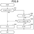
- FIG. 9 is a drawing illustrating a series of processes performed by a driving assistance device according to an exemplary embodiment.
- FIG. 10 is a drawing illustrating respective processes performed by a driving assistance device according to an exemplary embodiment.
- FIG. 11 is a drawing illustrating an optical flow.
- FIG. 12 is a flowchart illustrating a FOE learning process performed by a driving assistance device.
- a driving assistance device 100 is mounted on a vehicle VE (hereinafter, the vehicle mounted with the driving assistance device will be referred to as an own vehicle), and recognizes an object to be detected which exists around an own vehicle as a target. Furthermore, the object may include a preceding vehicle traveling in front of the own vehicle, an oncoming vehicle, moving objects such as a pedestrian existing around the own vehicle VE, etc., and stationary objects such as a guard rail, a traffic light, etc. Furthermore, the driving assistance device performs a function as a PCS (Pre-Crash Safety) system so as to avoid a collision with a recognized target or to reduce collision damage.
- the PCS system includes a pre-crash brake control, and the like which are automatically executed when a collision possibility is determined, etc.
- the driving assistance device 100 includes an imaging device 10 , an ECU 20 , and a controlled object 30 , all of which are configured to be connected via an in-vehicle LAN (Local Area Network) such as a CAN (Controller Area Network), and the like.
- LAN Local Area Network
- CAN Controller Area Network
- the imaging device 10 is a monocular imaging device 10 (one camera) such as a CCD camera, a CMOS image sensor, a near infrared camera, and the like.
- the imaging device 10 is mounted at a predetermined height at the center of a vehicle in a vehicle width direction, and captures a region extending in a predetermined angular range toward a front of the vehicle at every predetermined control period. Afterwards, an acquired image is transmitted to the ECU 20 .
- the ECU 20 which is a vehicle control device, is provided as a computer system including a CPU as a main body, and also includes a ROM, a RAM, an input/output interface, and other necessary components.
- Various functions of the ECU 20 which will be described hereinafter, are accomplished in a manner that the CPU executes a program stored in the ROM. Furthermore, the history of various data acquired by the ECU 20 is stored in the RAM.
- the ECU 20 includes a target recognition unit 21 recognizing an object to be detected which exists around the own vehicle as a target; a distance information acquisition unit 23 acquiring distance information of the target; a predicted collision time calculation unit 24 calculating a predicted collision time between the target and the own vehicle based upon a plurality of patterns; a deceleration state determination unit 25 determining whether or not the preceding vehicle is in a deceleration state; a possibility determination section 26 determining whether or not a collision possibility between the own vehicle and the preceding vehicle exists; and a use determination unit 27 selecting the predicted collision time to be used from among the predicted collision times of the plurality of patterns which are calculated by the predicted collision time calculation unit 24 .
- Respective functions thereof will be hereinafter described in detail.
- a controlled object 30 is a safety device driven by a control command from the ECU 20 , and includes an alarm device 31 and a brake device 32 .
- the alarm device 31 is a speaker or a display installed in a vehicle compartment of the own vehicle.
- the alarm device 31 informs a driver of a collision risk by outputting an alarm sound, an alarm message, and the like according to the control command from the ECU 20 .
- the brake device 32 is a braking device that brakes the own vehicle.
- the brake device 32 is operated according to the control command from the ECU 20 . More specifically, a braking force with respect to a brake operation by the driver is configured to be stronger (brake assist function), and an automatic brake is operated when the brake operation is not performed by the driver (automatic brake function).
- the target recognition unit 21 recognizes the object to be detected which is included in the image acquired by the imaging device 10 as the target. For example, an object which is extracted by performing a pattern matching method using an identification dictionary with respect to the image is recognized as the target.
- an identification dictionary a vehicle dictionary for identifying vehicles such as a preceding vehicle and an oncoming vehicle, a pedestrian dictionary for identifying a pedestrian, a stationary object dictionary for identifying a stationary object on a road (guard rail, etc.), etc. are provided.
- the distance information acquiring unit 23 acquires a relative distance D between the own vehicle and respective targets, a relative velocity V therebetween, and a relative acceleration ⁇ therebetween as distance information.
- the relative distance D is obtained by substituting coordinates (x, y) of the target in a current image and an image magnification ratio K into a well-known calculation model. For example, a Kalman filter is used as a calculation model.
- the relative velocity V is obtained by time differentiating the relative distance D.
- the relative acceleration ⁇ is obtained by time differentiating the relative velocity V. That is, the relative acceleration ⁇ may be obtained by time differentiating the relative distance D twice.
- the image magnification ratio K is a ratio of a target size (image region) on a current image to a target size (image region) on a past image.
- the image magnification ratio K is calculated by using a plurality of different calculation methods.
- a first image magnification ratio K 1 is obtained as the image magnification ratio K by using an LK method (Lucas-Kanade method) which is a combination of a well-known least squares method and a hill climbing method.
- a second image magnification ratio K 2 is obtained as the image magnification ratio K, based upon a change of a target size (image region) with respect to a time-varying image of the imaging device 10 , that is to say an image of two different frames.
- an image reliability level is evaluated, based upon whether or not the first image magnification ratio K 1 and the second image magnification ratio K 2 match each other. Evaluation of the image reliability level will be hereinafter described in detail.
- the predicted collision time calculation unit 24 calculates the predicted collision of a plurality of patterns.
- the predicted collision time is an evaluation value showing that the own vehicle will collide with an object in certain minutes when travelling at a current own vehicle speed. The lower the predicted collision time is, the higher a collision risk becomes, that is to say, the greater the predicted collision time is, the lower the collision risk becomes.
- TTC Time-To-Collision
- ETTC Enhanced TTC
- the TTC is a value obtained in a manner of dividing the relative distance D in a traveling direction of the own vehicle and the target by the relative velocity V between the own vehicle and the target, and for example, as shown in an equation 1, the TTC is calculated by using a motion equation of uniform linear motion.
- TTC D/V (1)
- the ETTC is a value obtained in consideration of the relative acceleration ⁇ between the own vehicle and the target, and, for example, as shown in an equation 2, is calculated by using a motion equation of uniform acceleration linear motion.
- EETC [ ⁇ V +( V 2 +2 ⁇ D ) ⁇ 1/2 ]/ ⁇ (2)
- the preceding vehicle approaches the own vehicle rapidly.
- the driving assistance can be performed at an earlier timing as the predicted collision time by using the ETTC considering the relative acceleration ⁇ with respect to the preceding vehicle.
- the relative acceleration ⁇ obtained by time differentiating the relative distance twice has a high possibility of including noise, errors, and the like in comparison with the relative distance D and the relative velocity V. Therefore, when using the ETTC as the predicted collision time, an alarm, automatic braking, and the like are operated at an unnecessary timing, such that the driver may feel a sense of incongruity.
- the ECU 20 does not perform the driving assistance based upon the ETTC.
- the ECU 20 uses the ETTC as the predicted collision time.
- the deceleration state determination unit 25 determines whether or not the preceding vehicle is in the deceleration state.
- the deceleration state of the preceding vehicle is obtained from the relative acceleration ⁇ , however, as described hereinabove, information corresponding to the relative acceleration ⁇ is easy to be influenced by the noise, the error, and the like. Therefore, the deceleration state determination unit 25 determines the deceleration state of the preceding vehicle by using the relative velocity V. Furthermore, in this case, a value that is obtained by subtracting a speed of the preceding vehicle from a speed of the own vehicle is defined as the relative velocity V.
- a past value P of the relative velocity V with respect to the preceding vehicle is sampled at plural points, and a variation ⁇ RS of the relative velocity V is calculated, based on which it is determined whether or not the preceding vehicle has a tendency to decelerate by using the variation ⁇ RS.
- the variation ⁇ RS is calculated as a speed variation per unit time of a change line by using the speed change line calculated based upon the least squares method, and the like.
- the variation ⁇ RS is an index for grasping a general tendency of the deceleration of the preceding vehicle and may be calculated when at least two past values P of the relative velocity V are provided.
- the threshold value Th 1 may be set, for example, by previously acquiring a deceleration level of the preceding vehicle in which the driver feels danger.
- the threshold value Th 2 may be set to a value having a predetermined hysteresis width with respect to the threshold value Th 1 , and the like.
- the possibility determination section 26 is provided with respective functions of a risk period determination unit 261 , a virtual deceleration determination unit 262 , and a reliability determination unit 263 , thereby having an effect of determining whether or not the collision possibility between the own vehicle and the preceding vehicle exists, based upon determination results of respective determination units.
- the risk period determination unit 261 determines whether or not there is a possibility that the driver drives the vehicle distractedly, that is to say, determines whether or not the driver is in a distracted driving state.
- the distracted driving state means a state where there is a possibility that the driver of the own vehicle may have a difficulty in responding to a movement of the preceding vehicle, that is to say, for example, the distracted driving state means a state where there is a possibility that the driver does not concentrate on driving because the drive does not keep his/her eyes to the front, and the like.
- the distracted driving state may occur, when a state in which the relative velocity V between the own vehicle and the preceding vehicle does not change (a state in which a vehicle-to-vehicle distance has not changed) keeps continuing for more than a certain period of time. Then, when the driver is in the distracted driving state, there is a high possibility that a response of the driver is delayed immediately after the preceding vehicle starts to decelerate, which may result in a high collision risk.
- the risk period determination unit 261 first determines that the driver is in the distracted driving state when the state in which the relative velocity between the own vehicle and the preceding vehicle does not change keeps continuing for a predetermined period (for example, from several seconds to several minutes). Specifically, when the driver is determined to be in the distracted driving state, a predetermined deceleration start period (several seconds) immediately after the preceding vehicle starts to decelerate and thus consequently the relative velocity V starts to increase is determined to be a risk period during which the collision risk between the own vehicle and the preceding vehicle increases.
- a predetermined deceleration start period severe seconds
- the virtual deceleration determination unit 262 determines that the collision possibility between the own vehicle and the preceding vehicle exists. Additionally, the lower limit value Th 3 of the allowed time may be set in advance based upon an experiment, and the like.
- the reliability determination unit 263 determines whether or not the image acquired by the imaging device 10 is reliable. In the exemplary embodiment, when a difference ⁇ k between the first image magnification ratio K 1 and the second image magnification ratio K 2 is lower than a predetermined value, it is determined that the image has the reliability. When the difference ⁇ k between the first image magnification ratio K 1 and the second image magnification ratio K 2 is greater than the predetermined value, it is determined that the image is not reliable. When it is determined that the image has the reliability, the image is used for calculating distance information. Meanwhile, when it is determined that the image does not have the reliability, the image is not used for calculating the distance information.
- the use determination unit 27 selects any one of the TTC and the ETTC as the predicted collision time based upon a determination result of the deceleration state determination unit 25 and the possibility determination section 26 . That is, when the deceleration state determination unit 25 determines that the preceding vehicle is in the deceleration state and when the possibility determination section 26 determines that the collision possibility between the own vehicle and the preceding vehicle exists, the use determination unit 27 determines that the ETTC is used for the predicted collision time. On the other hand, when the preceding vehicle is not in the deceleration state or when the possibility determination section 26 determines that the collision possibility between the own vehicle and the preceding vehicle does not exist, the use determination unit 27 determines that the TTC is used for the predicted collision time. That is, it is determined that the ETTC is not used as the predicted collision time.
- an image in front of the own vehicle is acquired by the monocular imaging device 10 at step S 11 , and an object to be detected which is included in the image acquired at step S 11 is recognized as a target at step S 12 .
- the preceding vehicle exists at step S 13 YES
- the relative distance D between the own vehicle and the preceding vehicle, the relative velocity V therebetween, and the relative acceleration ⁇ therebetween are acquired as the distance information at step S 14 .
- the pieces of distance information obtained therefrom are stored in the RAM as history.
- step S 15 it is determined whether or not the preceding vehicle is in the deceleration state at step S 15 .
- step S 16 it is determined whether or not there is the risk period in which the collision possibility between the own vehicle and the preceding vehicle exists at step S 16 .
- steps S 15 and S 16 respectively, respective processes of steps S 15 and S 16 will be hereinafter described in detail.
- step S 17 when the preceding vehicle decelerates at the virtual deceleration, it is determined whether or not the collision possibility between the own vehicle and the preceding vehicle exists at step S 17 .
- the collision possibility shown at steps S 16 and S 17 is a collision risk which potentially occurs, depending on the driver or performance of the vehicle body, and is used as an indicator different from the collision prediction based on the predicted collision time (TTC, ETTC).
- step S 18 it is determined whether or not the image acquired by the imaging device 10 is reliable at step S 18 .
- the difference ⁇ k between the first image magnification ratio K 1 and the second image magnification ratio K 2 is lower than the predetermined value, it is determined that the image is reliable.
- the predicted collision time (ETTC or TTC) to be used as the driving assistance and an operation timing of the controlled object 30 are compared with each other at step S 21 .
- the predicted collision time is equal to or lower than the operation timing
- any one of respective functions with respect to the controlled object 30 is executed.
- the predicted collision time is greater than the operation timing, the controlled object 30 is not operated and the process is terminated. Furthermore, when it is determined that there is no preceding vehicle in the image, the process is terminated.
- a determination process with respect to the deceleration state of the preceding vehicle at step S 15 is described hereinafter in detail.
- a variation ⁇ RS of the relative velocity V acquired as the distance information at step S 14 in FIG. 6 is obtained at step S 31 (refer to FIG. 3 ).
- the deceleration determination flag F 1 is turned ON when the variation ⁇ RS is determined to be greater than the threshold value Th 1 at step S 35 which will be described later.
- the deceleration determination flag F 1 When it is determined that the deceleration determination flag F 1 is turned ON at step S 32 (YES), it is determined whether or not the variation ⁇ RS is lower than the threshold value Th 2 at step S 33 . When the variation ⁇ RS is lower than the threshold value Th 2 at step S 33 (YES), the deceleration determination flag F 1 is turned OFF at step S 34 . When the variation ⁇ RS is greater than the threshold value Th 2 at step S 33 (NO), the process is terminated. In this case, the deceleration determination flag F 1 continues in an ON-state.
- the deceleration determination flag F 1 is turned OFF at step S 32 (NO)
- the deceleration determination flag F 1 is turned ON at step S 36 .
- the process is terminated. In this case, the decelerating determination flag F 1 continues in an OFF-state.
- FIG. 8 based upon history of the relative velocity V acquired at step S 14 in FIG. 6 , it is determined whether or not the relative velocity V is in a vicinity of zero at step S 41 .
- the relative velocity V is in the vicinity of zero at step S 41 (YES)
- the distracted driving state flag F 2 is in a process of being switched from ON to OFF at step S 51 .
- This process makes an affirmative determination at a timing when the relative velocity V increases due to the deceleration of the preceding vehicle.
- a risk period flag F 3 is turned ON at step S 52 .
- the distracted driving state flag F 2 is not in the process of being switched from ON to OFF at step S 51 (NO)
- the risk period flag F 3 continues in the OFF-state.
- the risk period flag F 3 is turned ON at step S 53 (YES)
- the risk period flag F 3 continues in the ON-state at step S 52 .
- the risk period flag F 3 is turned OFF at step S 55 .
- step S 16 in FIG. 6 when the risk period flag F 3 is turned ON, the risk period is determined at step S 16 (YES). In contrast, when the risk period flag F 3 is turned OFF, the risk period is not determined at step S 16 (NO).
- the distance information is acquired by using an image in which the difference ⁇ k between the first image magnification ratio K 1 and the second image magnification ratio K 2 is lower than the predetermined value.
- a preceding car M 2 does not decelerate and the relative velocity V between an own vehicle M 1 and the preceding vehicle M 2 is in the vicinity of zero (that is to say, below ⁇ V), such that the 11 C is used as the predicted collision time.
- the state where the relative velocity V is in the vicinity of zero becomes a time t 2 , which is a time after the determination period ⁇ t 1 elapses, the distracted driving state flag F 2 is turned ON.
- the preceding vehicle puts on a brake at a time t 3 such that the relative velocity V between the own vehicle M 1 and the preceding vehicle M 2 increases according to the deceleration of the preceding vehicle, the variation ⁇ RS of the relative velocity V becomes greater than the predetermined threshold Th 1 and thus the deceleration determination flag F 1 is turned ON.
- the preceding vehicle is determined to be in the deceleration state.
- the distracted driving state flag F 2 is switched from ON to OFF at the time t 3 and the elapsed time from the deceleration start is shorter than the time t 2 , the risk period flag F 3 is switched to ON.
- the ETTC is used as the predicted collision time. Additionally, in the case of a time t 4 at which the risk period ⁇ t 2 elapses, even though the deceleration determination flag F 1 is turned ON and the preceding vehicle is in the deceleration state, the process returns to the state where the TTC is used as the predicted collision time. That is, in the case of a period ⁇ t 3 , when the preceding vehicle is in the deceleration state, the TTC becomes used as the predicted collision time in FIG. 10 .
- the driving assistance can be performed at an earlier timing in consideration of the deceleration of the preceding vehicle by using the ETTC in consideration of the relative acceleration of the preceding vehicle as the predicted collision time.
- distance information of the preceding vehicle relative distance, relative velocity, relative acceleration
- processes of time differentiating the relative velocity, and the like are required so as to achieve information on the relative acceleration ⁇ , there is a high possibility of including noise, errors, etc. in comparison with the relative distance D, the relative velocity V, etc.
- the driving assistance systems such as the alarm and the automatic braking, and the like may be unnecessarily operated at a timing when a driver does not want to perform the driving assistance, such that the driver may feel the sense of incongruity.
- the preceding vehicle decelerates, when the collision possibility between the own vehicle and the preceding vehicle does not exist, the driving assistance using the ETTC at an early timing is not required.
- the ETTC is used as the predicted collision time. In other words, even though the preceding vehicle is in the deceleration state, the ETTC is not used as the predicted collision time when the collision possibility between the own vehicle and the preceding vehicle does not exist.
- a chance of performing the driving assistance based upon the ETTC is configured to be limited, thereby having effects of suppressing the unnecessary operation of the driving assistance and of more appropriately performing the driving assistance of the own vehicle.
- the collision avoidance operation by the driver is delayed, such that the collision possibility increases.
- it is preferable that the collision avoidance is performed at an early timing by the ETTC.
- the driving assistance using the ETTC at the early timing is not necessarily required. Therefore, even though the preceding vehicle is in the deceleration state, the ETTC is not used as the predicted collision time when the driver is not in the distracted driving state. As described hereinabove, it is advantageously possible to suppress the unnecessary operation of the driving assistance, thereby more appropriately performing the driving assistance of the vehicle.
- the ETTC is configured to be used as the predicted collision time. In other words, if it is not determined that the vehicle is in the distracted driving state immediately after the preceding vehicle starts to decelerate, the ETTC is not used as the predicted collision time. Furthermore, even though the vehicle in the distracted driving state, the ETTC is not used as the predicted collision time in a case where it is not a state immediately after the preceding vehicle starts to decelerate. As described hereinabove, it is possible to suppress the unnecessary operation of the driving assistance, thereby more appropriately performing the driving assistance of the own vehicle.
- the predicted collision time required until the own vehicle collides with the preceding vehicle is calculated as the virtual time, based upon the virtual deceleration VD, the relative distance D, and the relative velocity V on the assumption that the preceding vehicle decelerates at a predetermined virtual deceleration VD as well as the relative distance D of the preceding vehicle and the relative velocity V thereof.
- the ETTC is used as the predicted collision time on the condition that the virtual time is lower than the lower limit value of the allowed time in which the collision avoidance operation by the driver is possible.
- the ETTC having low accuracy is not configured to be used as the predicted collision time. As described hereinabove, it is possible to suppress the unnecessary operation of the driving assistance, thereby more appropriately performing the driving assistance of the own vehicle.
- the reliability of the image can be evaluated easily in comparison with a matching degree of the image magnification rate K (K 1 , K 2 ) obtained by a different method.
- the chance of performing the driving assistance based upon the ETTC is configured to be limited, thereby having the effects of suppressing the unnecessary operation of the driving assistance and of more appropriately performing the driving assistance of the own vehicle.
- the TTC does not use the relative acceleration, a possibility that the noise, the error, and the like are included therein is lower than ETTC.
- the preceding vehicle is in the deceleration state and the collision possibility between the own vehicle and the preceding vehicle does not exist, it is advantageously possible to suppress the unnecessary operation of the driving assistance by using the TTC as the predicted collision time.
- the vehicle control is configured to be executed by using any one of the ETTC considering the relative acceleration ⁇ and the TTC not considering the relative acceleration ⁇ .
- the chance of performing the driving assistance based on the ETTC in the deceleration state of the own vehicle is configured to be limited, and thus consequently, it is advantageously possible to suppress the unnecessary operation of the driving assistance.
- the possibility determination section 26 may include at least any one of functions of the risk period determination unit 261 , the virtual deceleration determination unit 262 , and the reliability determination unit 263 . That is, in the process in FIG. 6 , at least one of respective processes at steps S 16 to S 18 may be executed, and the respective processes can be omitted. Furthermore, in FIG. 6 , order of respective processes at steps S 15 to S 18 can be replaced.
- the reliability determination unit 263 may be a unit determining that the image reliability exists on the condition that learning of an image FOE is completed. That is, in a state where the learning of a point at infinity (FOE: Focus of Expansion) of the monocular imaging device 10 is not completed, accuracy of the distance information acquired from the image may not be secured. Accordingly, it is determined that the image is reliable on the condition that the learning of the FOE is completed.
- FOE Focus of Expansion
- step S 61 learning according to an optical flow starts at step S 61 when the vehicle is traveling with respect to a flow chart of FIG. 11 .
- a plurality of feature points are set at edges of images, and a vector (optical flow) is obtained as to how the plurality of feature points move according to time series, based on which a position of the FOE is obtained by using the optical flow.
- the optical flow it is detected that stationary objects such as a white line or a tree move so as to appear from the FOE. Furthermore, moving objects moving from left and right images such as a pedestrian running out into a road or a bicycle are detected so as to move with respect to a vanishing point different from the FOE. In other words, when an appearance point of the object is obtained, the position of the FOE can be acquired. Since a process of detecting the position of the FOE using the optical flow is completed by performing an image process with respect to images of several frames, it is advantageously possible to determine the position of the FOE in a relatively short time.
- step S 62 learning with respect to the position of the FOE according to white line recognition starts at step S 62 .
- the position of the FOE is determined, for example, by recognizing white lines positioned on the left and right side of the vehicle from the image as shown in FIG. 12 , and by obtaining an intersection point on extended lines of the white lines. In this way, in a process of obtaining the position of the FOE based upon the positions of the white lines, the position of the FOE can be accurately obtained. Meanwhile, since this process requires that the own vehicle is traveling on a straight road without undulation and the white line exists on the left and right side of the own vehicle. It may take time to determine the position of the FOE.
- step S 63 it is determined whether or not the learning of the position of the FOE by the optical flow is terminated (completed) at step S 63 .
- step S 64 it is determined whether or not the learning of the position of the FOE according to the white line recognition is terminated at step S 64 .
- step S 64 the position of the FOE is recorded in a memory such as a RAM, and simultaneously a FOE learning process is terminated at step S 65 .
- the FOE learning process is executed repeatedly at regular time intervals or at an arbitrary timing, thereby accumulating the position of the FOE in the memory.
- step S 63 and S 64 When a negative determination is made at steps S 63 and S 64 , the process returns to step S 63 . According to the process described hereinabove, the deterioration of the calculation accuracy with respect to the ETTC due to the low accuracy of the image can be suppressed.
- a length of the risk period ⁇ t 2 may be variably set in response to an increasing degree of the relative velocity V after the distracted driving state is determined. For example, it is assumed that the lower the variation ⁇ RS of the relative velocity V is, the longer a period, during which the collision risk increases, is after the deceleration of the preceding vehicle starts, such that the risk period ⁇ t 2 is configured to be long.
- the risk period flag F 3 may be selected to be turned ON or OFF. That is, when the relative velocity V changes in the distracted driving state of the own vehicle, and further when the own vehicle and the preceding vehicle are in the state of approaching each other, the risk period flag F 3 is turned ON. When the own vehicle and the preceding vehicle are in the state of being separate from each other, the risk period flag F 3 is turned OFF. Furthermore, the state of whether the own vehicle and the preceding vehicle are approaching each other or moving away from each other may be determined by obtaining a vector of the relative velocity V. As described hereinabove, the risk period may be determined on the condition that the own vehicle and the preceding vehicle are in the state of approaching each other in the distracted driving state of the own vehicle.
- the risk period determination unit 261 determines whether or not the driver is in the distracted driving state based upon the relative velocity V between the own vehicle and the preceding vehicle.
- a camera may be installed in the passenger compartment of the own vehicle so as to capture a facial expression of the driver. Afterwards, an image process is performed on an image captured by the camera, and when it is detected that the driver has a facial expression in which the driver does not concentrate on driving, it may be determined that the driver is in the distracted driving state. For example, when it is detected that the driver has a facial expression in which the drive looks sideways or does not look to the front carefully, and the like, it may be determined that the driver is in the distracted driving state.
- the risk period determination unit 261 may determine the risk period, based upon whether or not the driver is determined to be in the distracted driving state regardless of the elapsed time from the deceleration start. That is, in the determination process of the risk period at step S 16 in FIG. 6 , the process in FIG. 8 is performed and the process in FIG. 9 is omitted. In this case, at step S 16 in FIG. 6 , when it is determined that the distracted driving state flag F 2 is turned ON at step S 43 (YES) in the process in FIG. 8 , the risk period is determined at step S 16 (YES).
- the risk period is not determined at step S 16 (NO). Furthermore, it may be determined that the distracted driving state is canceled when the driver's vehicle operation is performed.
- the driving assistance device 100 may include a radar device.
- the radar device is a well-known millimeter wave radar in which a high-frequency signal in a millimeter wave band is used as a transmission wave, and is installed at a front end part of the own vehicle.
- a region existing within a predetermined detection angle is configured as a detection range where a target is detectable, based on which the radar device detects a position of the target existing within the detection range. More specifically, a probing wave is transmitted at a predetermined cycle, and a reflected wave is received by a plurality of antennas.
- the relative distance D of the target is calculated based upon a transmission time of the probing wave and a reception time of the reflected wave. Additionally, the relative velocity V is calculated based upon frequency which is changed by the Doppler effect of the reflected wave reflected by the target.
- the relative distance D, the relative velocity V, and the relative acceleration ⁇ are calculated from the image of the imaging device 10 .
- the distance information acquisition unit 23 acquires a differential value (change amount) of the image magnification ratio as information corresponding to the relative acceleration.
- the predicted collision time calculation unit 24 may calculate the ETTC in consideration of the differential value of the image magnification ratio. Referring to U.S. Patent Application Publication No. 886179, detailed descriptions of an ETTC calculation method using the differential value of the image magnification ratio are disclosed.
- the imaging device 10 may include the distance information acquisition unit 23 and the predicted collision time calculation unit 24 . That is, the imaging device 10 may acquire distance information between the own vehicle and respective targets and may calculate the predicted collision time based upon the acquired distance information.
Landscapes
- Engineering & Computer Science (AREA)
- Physics & Mathematics (AREA)
- General Physics & Mathematics (AREA)
- Automation & Control Theory (AREA)
- Transportation (AREA)
- Mechanical Engineering (AREA)
- Multimedia (AREA)
- Theoretical Computer Science (AREA)
- Computer Vision & Pattern Recognition (AREA)
- Traffic Control Systems (AREA)
- Image Analysis (AREA)
Abstract
Description
TTC=D/V (1)
EETC=[{−V+(V 2+2α·D)}1/2]/α (2)
0.5·VD·EETC22 +V·EETC2=D (3)
- 10 . . . imaging device
- 20 . . . ECU
- 24 . . . predicted collision time calculation unit
- 25 . . . deceleration state determination unit
- 261 . . . risk period determination unit
- 262 . . . virtual deceleration determination unit
- 263 . . . reliability determination unit
Claims (19)
Applications Claiming Priority (2)
| Application Number | Priority Date | Filing Date | Title |
|---|---|---|---|
| JP2016-241222 | 2016-12-13 | ||
| JP2016241222A JP6690517B2 (en) | 2016-12-13 | 2016-12-13 | Driving support device and driving support method |
Publications (2)
| Publication Number | Publication Date |
|---|---|
| US20180162394A1 US20180162394A1 (en) | 2018-06-14 |
| US10576973B2 true US10576973B2 (en) | 2020-03-03 |
Family
ID=62488643
Family Applications (1)
| Application Number | Title | Priority Date | Filing Date |
|---|---|---|---|
| US15/839,604 Active 2038-02-25 US10576973B2 (en) | 2016-12-13 | 2017-12-12 | Driving assistance device and driving assistance method |
Country Status (2)
| Country | Link |
|---|---|
| US (1) | US10576973B2 (en) |
| JP (1) | JP6690517B2 (en) |
Families Citing this family (23)
| Publication number | Priority date | Publication date | Assignee | Title |
|---|---|---|---|---|
| CN110177722B (en) * | 2017-01-19 | 2022-07-01 | 本田技研工业株式会社 | Vehicle control system, vehicle control method, and storage medium |
| EP3540710A1 (en) * | 2018-03-14 | 2019-09-18 | Honda Research Institute Europe GmbH | Method for assisting operation of an ego-vehicle, method for assisting other traffic participants and corresponding assistance systems and vehicles |
| DE112018007130B4 (en) * | 2018-03-26 | 2024-05-02 | Mitsubishi Electric Corporation | INFORMATION PROCESSING DEVICE, INFORMATION PROCESSING METHOD AND INFORMATION PROCESSING PROGRAM |
| DE112018007454T5 (en) * | 2018-04-11 | 2021-02-11 | Mitsubishi Electric Corporation | Occupant condition determination device, warning output control device, and occupant condition determination method |
| US11163317B2 (en) * | 2018-07-31 | 2021-11-02 | Honda Motor Co., Ltd. | System and method for shared autonomy through cooperative sensing |
| US11181929B2 (en) | 2018-07-31 | 2021-11-23 | Honda Motor Co., Ltd. | System and method for shared autonomy through cooperative sensing |
| EP3849932B1 (en) | 2018-09-13 | 2024-12-18 | Crown Equipment Corporation | System and method for controlling a maximum vehicle speed for an industrial vehicle based on a calculated load |
| US11364929B2 (en) | 2019-01-04 | 2022-06-21 | Toyota Research Institute, Inc. | Systems and methods for shared control of a vehicle |
| KR102734270B1 (en) * | 2019-06-04 | 2024-11-26 | 주식회사 에이치엘클레무브 | Apparatus and method for driver assistance |
| US10937218B2 (en) * | 2019-07-01 | 2021-03-02 | Microsoft Technology Licensing, Llc | Live cube preview animation |
| US11360480B2 (en) | 2019-08-21 | 2022-06-14 | Zoox, Inc. | Collision zone detection for vehicles |
| US11225247B2 (en) * | 2019-08-21 | 2022-01-18 | Zoox, Inc. | Collision prediction and avoidance for vehicles |
| JP7425942B2 (en) * | 2019-12-06 | 2024-02-01 | 株式会社デンソー | Driving assistance devices and programs |
| JP2021092996A (en) * | 2019-12-11 | 2021-06-17 | 国立大学法人 東京大学 | Measurement system, vehicle, measurement method, measurement device and measurement program |
| JP2021098450A (en) | 2019-12-23 | 2021-07-01 | ロベルト・ボッシュ・ゲゼルシャフト・ミト・ベシュレンクテル・ハフツングRobert Bosch Gmbh | Vehicle brake system |
| US11999348B2 (en) * | 2020-01-27 | 2024-06-04 | Tusimple, Inc. | Adaptive brake mode selection |
| US11433885B1 (en) | 2020-08-20 | 2022-09-06 | Zoox, Inc. | Collision detection for vehicles |
| DE102020214843A1 (en) * | 2020-11-26 | 2022-06-02 | Volkswagen Aktiengesellschaft | Method for representing a virtual element |
| CN112793566B (en) * | 2020-12-02 | 2022-03-25 | 上海汽车集团股份有限公司 | Collision avoidance method and device |
| JP7409296B2 (en) * | 2020-12-23 | 2024-01-09 | トヨタ自動車株式会社 | collision avoidance system |
| JP7650422B2 (en) * | 2022-10-12 | 2025-03-25 | トヨタ自動車株式会社 | Apparatus, method, and program for detecting deceleration of a preceding vehicle |
| CN118701043A (en) * | 2024-06-20 | 2024-09-27 | 理工雷科智途(北京)科技有限公司 | A roadway emergency braking method based on perception fusion control decision |
| CN120756442B (en) * | 2025-09-11 | 2025-11-18 | 安车智行(北京)科技有限公司 | A passive safe distance control system based on monocular perception |
Citations (8)
| Publication number | Priority date | Publication date | Assignee | Title |
|---|---|---|---|---|
| US20130335213A1 (en) * | 2011-02-16 | 2013-12-19 | Toyota Motor Engineering & Manufacturing North America, Inc. | Lane departure warning/assistance method and system having a threshold adjusted based on driver impairment determination using pupil size and driving patterns |
| US8861792B2 (en) | 2004-04-08 | 2014-10-14 | Mobileye Technologies Ltd. | Collison warning system |
| US20150148985A1 (en) * | 2013-11-28 | 2015-05-28 | Hyundai Mobis Co., Ltd. | Vehicle driving assistance device and automatic activating method of vehicle driving assistance function by the same |
| US20150266473A1 (en) * | 2012-11-13 | 2015-09-24 | Toyota Jidosha Kabushiki Kaisha | Driving support apparatus and driving support method |
| US20180017679A1 (en) * | 2015-01-30 | 2018-01-18 | Trinamix Gmbh | Detector for an optical detection of at least one object |
| US20180072310A1 (en) * | 2011-02-18 | 2018-03-15 | Honda Motor Co., Ltd. | System and method for responding to driver behavior |
| US20180136319A1 (en) * | 2015-04-22 | 2018-05-17 | Trinamix Gmbh | Detector for an optical detection of at least one object |
| US20180281763A1 (en) * | 2015-11-06 | 2018-10-04 | Advics Co., Ltd. | Vehicle travel assistance system |
Family Cites Families (6)
| Publication number | Priority date | Publication date | Assignee | Title |
|---|---|---|---|---|
| JP3957057B2 (en) * | 2002-04-26 | 2007-08-08 | ダイハツ工業株式会社 | Vehicle traveling control apparatus and method |
| JP2011121491A (en) * | 2009-12-11 | 2011-06-23 | Toyota Motor Corp | Driving support device |
| JP2012053746A (en) * | 2010-09-02 | 2012-03-15 | Suzuki Motor Corp | Vehicle control device |
| JP6372228B2 (en) * | 2014-08-01 | 2018-08-15 | 株式会社デンソー | Estimated collision time calculation device |
| JP6365141B2 (en) * | 2014-09-04 | 2018-08-01 | トヨタ自動車株式会社 | Vehicle control device |
| JP6432423B2 (en) * | 2015-03-31 | 2018-12-05 | 株式会社デンソー | Object detection apparatus and object detection method |
-
2016
- 2016-12-13 JP JP2016241222A patent/JP6690517B2/en active Active
-
2017
- 2017-12-12 US US15/839,604 patent/US10576973B2/en active Active
Patent Citations (8)
| Publication number | Priority date | Publication date | Assignee | Title |
|---|---|---|---|---|
| US8861792B2 (en) | 2004-04-08 | 2014-10-14 | Mobileye Technologies Ltd. | Collison warning system |
| US20130335213A1 (en) * | 2011-02-16 | 2013-12-19 | Toyota Motor Engineering & Manufacturing North America, Inc. | Lane departure warning/assistance method and system having a threshold adjusted based on driver impairment determination using pupil size and driving patterns |
| US20180072310A1 (en) * | 2011-02-18 | 2018-03-15 | Honda Motor Co., Ltd. | System and method for responding to driver behavior |
| US20150266473A1 (en) * | 2012-11-13 | 2015-09-24 | Toyota Jidosha Kabushiki Kaisha | Driving support apparatus and driving support method |
| US20150148985A1 (en) * | 2013-11-28 | 2015-05-28 | Hyundai Mobis Co., Ltd. | Vehicle driving assistance device and automatic activating method of vehicle driving assistance function by the same |
| US20180017679A1 (en) * | 2015-01-30 | 2018-01-18 | Trinamix Gmbh | Detector for an optical detection of at least one object |
| US20180136319A1 (en) * | 2015-04-22 | 2018-05-17 | Trinamix Gmbh | Detector for an optical detection of at least one object |
| US20180281763A1 (en) * | 2015-11-06 | 2018-10-04 | Advics Co., Ltd. | Vehicle travel assistance system |
Also Published As
| Publication number | Publication date |
|---|---|
| US20180162394A1 (en) | 2018-06-14 |
| JP2018097582A (en) | 2018-06-21 |
| JP6690517B2 (en) | 2020-04-28 |
Similar Documents
| Publication | Publication Date | Title |
|---|---|---|
| US10576973B2 (en) | Driving assistance device and driving assistance method | |
| CN108263279B (en) | Sensor integration based pedestrian detection and pedestrian collision avoidance apparatus and method | |
| US9499171B2 (en) | Driving support apparatus for vehicle | |
| CN109204311B (en) | A vehicle speed control method and device | |
| CN104118382B (en) | Collision determines that equipment, collision mitigate equipment and collision determination method | |
| CN108263278B (en) | Pedestrian detection and pedestrian anti-collision device and method based on sensor integration | |
| US10227072B2 (en) | Travel control device | |
| US9493163B2 (en) | Driving support apparatus for vehicle | |
| KR101276871B1 (en) | Method and apparatus for collision avoidance of vehicle | |
| CN107615356B (en) | Vehicle control device and vehicle control method | |
| US9797734B2 (en) | Object recognition apparatus | |
| JP6327708B2 (en) | Vehicle driving support device | |
| JP6404634B2 (en) | Consistent behavior generation of predictive advanced driver assistance systems | |
| US10000208B2 (en) | Vehicle control apparatus | |
| CN109562761B (en) | Vehicle control device and vehicle control method | |
| JP6319181B2 (en) | Vehicle control apparatus and vehicle control method | |
| JP6412346B2 (en) | Vehicle driving support device | |
| CN107408345A (en) | Decision method and device be present in thing mark | |
| JP2018002083A (en) | Vehicle control device | |
| WO2016158944A1 (en) | Vehicle control device and vehicle control method | |
| WO2017110871A1 (en) | Vehicle control device and vehicle control method | |
| US20190389461A1 (en) | Vehicle control system | |
| JP2017068461A (en) | Vehicle driving support device | |
| KR20210029927A (en) | RaDAR apparatus, recognizing target Method of RaDAR apparatus, and system for controlling vehicle including it | |
| US10857998B2 (en) | Vehicle control device operating safety device based on object position |
Legal Events
| Date | Code | Title | Description |
|---|---|---|---|
| FEPP | Fee payment procedure |
Free format text: ENTITY STATUS SET TO UNDISCOUNTED (ORIGINAL EVENT CODE: BIG.); ENTITY STATUS OF PATENT OWNER: LARGE ENTITY |
|
| STPP | Information on status: patent application and granting procedure in general |
Free format text: DOCKETED NEW CASE - READY FOR EXAMINATION |
|
| AS | Assignment |
Owner name: DENSO CORPORATION, JAPAN Free format text: ASSIGNMENT OF ASSIGNORS INTEREST;ASSIGNOR:KAMIYA, KEI;REEL/FRAME:045136/0233 Effective date: 20171222 |
|
| STPP | Information on status: patent application and granting procedure in general |
Free format text: NON FINAL ACTION MAILED |
|
| STPP | Information on status: patent application and granting procedure in general |
Free format text: RESPONSE TO NON-FINAL OFFICE ACTION ENTERED AND FORWARDED TO EXAMINER |
|
| STPP | Information on status: patent application and granting procedure in general |
Free format text: NOTICE OF ALLOWANCE MAILED -- APPLICATION RECEIVED IN OFFICE OF PUBLICATIONS |
|
| STPP | Information on status: patent application and granting procedure in general |
Free format text: PUBLICATIONS -- ISSUE FEE PAYMENT RECEIVED |
|
| STCF | Information on status: patent grant |
Free format text: PATENTED CASE |
|
| MAFP | Maintenance fee payment |
Free format text: PAYMENT OF MAINTENANCE FEE, 4TH YEAR, LARGE ENTITY (ORIGINAL EVENT CODE: M1551); ENTITY STATUS OF PATENT OWNER: LARGE ENTITY Year of fee payment: 4 |