US10575444B2 - Electronic apparatus - Google Patents
Electronic apparatus Download PDFInfo
- Publication number
- US10575444B2 US10575444B2 US15/960,609 US201815960609A US10575444B2 US 10575444 B2 US10575444 B2 US 10575444B2 US 201815960609 A US201815960609 A US 201815960609A US 10575444 B2 US10575444 B2 US 10575444B2
- Authority
- US
- United States
- Prior art keywords
- heat sink
- housing
- heat
- heating component
- air intake
- Prior art date
- Legal status (The legal status is an assumption and is not a legal conclusion. Google has not performed a legal analysis and makes no representation as to the accuracy of the status listed.)
- Expired - Fee Related
Links
Images


Classifications
-
- H—ELECTRICITY
- H05—ELECTRIC TECHNIQUES NOT OTHERWISE PROVIDED FOR
- H05K—PRINTED CIRCUITS; CASINGS OR CONSTRUCTIONAL DETAILS OF ELECTRIC APPARATUS; MANUFACTURE OF ASSEMBLAGES OF ELECTRICAL COMPONENTS
- H05K7/00—Constructional details common to different types of electric apparatus
- H05K7/20—Modifications to facilitate cooling, ventilating, or heating
- H05K7/2039—Modifications to facilitate cooling, ventilating, or heating characterised by the heat transfer by conduction from the heat generating element to a dissipating body
- H05K7/20436—Inner thermal coupling elements in heat dissipating housings, e.g. protrusions or depressions integrally formed in the housing
-
- G—PHYSICS
- G06—COMPUTING OR CALCULATING; COUNTING
- G06F—ELECTRIC DIGITAL DATA PROCESSING
- G06F1/00—Details not covered by groups G06F3/00 - G06F13/00 and G06F21/00
- G06F1/16—Constructional details or arrangements
- G06F1/18—Packaging or power distribution
- G06F1/181—Enclosures
-
- G—PHYSICS
- G06—COMPUTING OR CALCULATING; COUNTING
- G06F—ELECTRIC DIGITAL DATA PROCESSING
- G06F1/00—Details not covered by groups G06F3/00 - G06F13/00 and G06F21/00
- G06F1/16—Constructional details or arrangements
- G06F1/20—Cooling means
-
- H—ELECTRICITY
- H01—ELECTRIC ELEMENTS
- H01L—SEMICONDUCTOR DEVICES NOT COVERED BY CLASS H10
- H01L23/00—Details of semiconductor or other solid state devices
- H01L23/34—Arrangements for cooling, heating, ventilating or temperature compensation ; Temperature sensing arrangements
- H01L23/46—Arrangements for cooling, heating, ventilating or temperature compensation ; Temperature sensing arrangements involving the transfer of heat by flowing fluids
- H01L23/467—Arrangements for cooling, heating, ventilating or temperature compensation ; Temperature sensing arrangements involving the transfer of heat by flowing fluids by flowing gases, e.g. air
-
- H—ELECTRICITY
- H05—ELECTRIC TECHNIQUES NOT OTHERWISE PROVIDED FOR
- H05K—PRINTED CIRCUITS; CASINGS OR CONSTRUCTIONAL DETAILS OF ELECTRIC APPARATUS; MANUFACTURE OF ASSEMBLAGES OF ELECTRICAL COMPONENTS
- H05K7/00—Constructional details common to different types of electric apparatus
- H05K7/20—Modifications to facilitate cooling, ventilating, or heating
- H05K7/20009—Modifications to facilitate cooling, ventilating, or heating using a gaseous coolant in electronic enclosures
- H05K7/20127—Natural convection
-
- H—ELECTRICITY
- H05—ELECTRIC TECHNIQUES NOT OTHERWISE PROVIDED FOR
- H05K—PRINTED CIRCUITS; CASINGS OR CONSTRUCTIONAL DETAILS OF ELECTRIC APPARATUS; MANUFACTURE OF ASSEMBLAGES OF ELECTRICAL COMPONENTS
- H05K7/00—Constructional details common to different types of electric apparatus
- H05K7/20—Modifications to facilitate cooling, ventilating, or heating
- H05K7/2029—Modifications to facilitate cooling, ventilating, or heating using a liquid coolant with phase change in electronic enclosures
- H05K7/20336—Heat pipes, e.g. wicks or capillary pumps
-
- H10W40/43—
-
- G—PHYSICS
- G06—COMPUTING OR CALCULATING; COUNTING
- G06F—ELECTRIC DIGITAL DATA PROCESSING
- G06F2200/00—Indexing scheme relating to G06F1/04 - G06F1/32
- G06F2200/20—Indexing scheme relating to G06F1/20
- G06F2200/201—Cooling arrangements using cooling fluid
-
- H—ELECTRICITY
- H01—ELECTRIC ELEMENTS
- H01L—SEMICONDUCTOR DEVICES NOT COVERED BY CLASS H10
- H01L23/00—Details of semiconductor or other solid state devices
- H01L23/34—Arrangements for cooling, heating, ventilating or temperature compensation ; Temperature sensing arrangements
- H01L23/42—Fillings or auxiliary members in containers or encapsulations selected or arranged to facilitate heating or cooling
- H01L23/427—Cooling by change of state, e.g. use of heat pipes
-
- H—ELECTRICITY
- H05—ELECTRIC TECHNIQUES NOT OTHERWISE PROVIDED FOR
- H05K—PRINTED CIRCUITS; CASINGS OR CONSTRUCTIONAL DETAILS OF ELECTRIC APPARATUS; MANUFACTURE OF ASSEMBLAGES OF ELECTRICAL COMPONENTS
- H05K7/00—Constructional details common to different types of electric apparatus
- H05K7/20—Modifications to facilitate cooling, ventilating, or heating
- H05K7/20709—Modifications to facilitate cooling, ventilating, or heating for server racks or cabinets; for data centers, e.g. 19-inch computer racks
- H05K7/208—Liquid cooling with phase change
- H05K7/20809—Liquid cooling with phase change within server blades for removing heat from heat source
-
- H10W40/73—
Definitions
- a cooling device including two heat pipes having first end portions connected to different locations of a heat receiving portion in contact with a heating component on a circuit board and second end portions connected to respective finned structures outside the circuit board.
- This cooling device includes a fan for ejecting air into the finned structures along the air intake surfaces of the finned structures, and the fan is disposed in a gap between the finned structures.
- heat-pipe cooling device in which an intermediate portion of a heat pipe having a substantially U shape or substantially V shape is fixed to a heat receiving member and opposite end portions of the heat pipe are connected to a plurality of radiating plates arranged in parallel with each other.
- the opposite end portions of the heat pipe are connected to separate radiating plates.
- an electronic apparatus includes a housing, a heating component arranged inside the housing, a plurality of heat sinks arranged inside the housing, a heat transport member coupled such that heat is transferred from the heating component to the heat sinks, air intake regions positioned in the housing, corresponding to the respective heat sinks, and arranged below and close to the respective heat sinks, and an air exhaust region positioned in the housing and arranged above the heat sinks.
- FIG. 1 is a longitudinal sectional view that illustrates an electronic apparatus according to a first embodiment
- FIG. 2 is a cross-sectional view taken along the line II-II in FIG. 1 and illustrating the electronic apparatus according to the first embodiment;
- FIG. 3 is a longitudinal sectional view that illustrates an electronic apparatus according to a second embodiment
- FIG. 4 is a cross-sectional view taken along the line IV-IV in FIG. 3 and illustrating the electronic apparatus according to the second embodiment
- FIG. 5 is a longitudinal sectional view that illustrates an electronic apparatus according to a third embodiment
- FIG. 6 is a cross-sectional view taken along the line VI-VI in FIG. 5 and illustrating the electronic apparatus according to the third embodiment
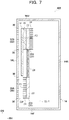
- FIG. 7 is a horizontal sectional view that illustrates an electronic apparatus according to a fourth embodiment
- FIG. 8 is a horizontal sectional view that illustrates an electronic apparatus according to a fifth embodiment
- FIG. 9 is a longitudinal sectional view that illustrates an electronic apparatus according to a sixth embodiment.
- FIG. 10 is a cross-sectional view taken along the line X-X in FIG. 9 and illustrating the electronic apparatus according to the sixth embodiment;
- FIG. 11A is a cross-sectional view that illustrates a fragment of an electronic apparatus according to a variation.
- FIG. 11B is a cross-sectional view that illustrates a fragment of an electronic apparatus according to another variation.
- an electronic apparatus 102 includes a housing 14 .
- the housing 14 is a box member having a rectangular parallelepiped shape and has a right surface 14 R, left surface 14 L, back surface 14 U, front surface 14 F, top surface 14 T, and bottom surface 14 B.
- the right-hand side in the width direction, deep side in the depth direction, and upper side in the vertical direction of the housing 14 are indicated by the arrows RH, DB, and UP, respectively.
- the center of the housing 14 in the width direction is indicated by a center line CL- 1 .
- the center line CL- 1 represents a face in the center of the gap between the right surface 14 R and left surface 14 L and in parallel with the right surface 14 R and left surface 14 L.
- the electronic apparatus is the one in which the height H 1 is longer than the width W 1 of the housing 14 and the housing 14 is vertically oriented.
- a substrate 16 is arranged inside the housing 14 .
- the substrate 16 has a rectangular planar shape and is oriented such that the orientation of its longer side coincides with the vertical direction and the orientation of its shorter side coincides with the width direction and such that it is parallel with the back surface 14 U and is on a deeper side.
- One example of the substrate 16 may be attached to the housing 14 with a fastener, such as a bolt or clip.
- a heating component 18 is mounted on the substrate 16 .
- the heating component 18 may be an electronic component, such as an integrated circuit, and produces heat during operation.
- the heating component 18 is mounted in a location that is central in the width direction (direction of the shorter side) and that is in a lower portion in the vertical direction (direction of the longer side) of the substrate 16 .
- the location in which the heating component 18 is mounted on the substrate 16 is not limited to specific ones.
- a plurality of heat sinks 20 are arranged inside the housing 14 .
- two heat sinks 20 are spaced apart from each other in the width direction and are distinguished as heat sinks 20 A and 20 B as appropriate.
- the heat sinks 20 A and 20 B are symmetrical in location and shape with respect to the center line CL- 1 .
- Each of the heat sinks 20 includes a rectangular planar base plate 22 and a plurality of fins 24 extending from the base plate 22 .
- the base plate 22 is arranged in parallel with the right surface 14 R and left surface 14 L of the housing 14 .
- the plurality of fins 24 in each of the heat sinks 20 are planar, spaced apart from each other at regular intervals, and arranged in parallel with each other. Each of the fins 24 is oriented such that it extends along the vertical direction.
- the fins 24 in each of the heat sinks 20 extend from the base plate 22 toward the corresponding right surface 14 R or left surface 14 L, that is, outward in the width direction (direction of the arrow RH and its opposite direction).
- the heat sink 20 A and right surface 14 R are not in contact with each other, and a gap 26 A is present between the heat sink 20 A and right surface 14 R.
- the heat sink 20 B and left surface 14 L are not in contact with each other, and a gap 26 B is present between the heat sink 20 B and left surface 14 L.
- neither of the plurality of heat sinks 20 is in contact with the heating component 18 .
- Each of the plurality of heat sinks 20 is coupled to the heating component 18 with a heat transport member 28 .
- the heat transport member 28 is a member for transporting heat from a higher temperature side to a lower temperature side.
- One example of the heat transport member 28 may be a heat pipe containing a heat transport medium (for example, water or oil).
- the heating component 18 corresponds to the higher temperature side
- the heat sink 20 corresponds to the lower temperature side. Accordingly, the heat is transported by the heat transport member 28 from the heating component 18 to the heat sink 20 .
- the housing 14 has one or more air inlets 30 .
- the housing 14 has a plurality of air inlets 30 extending through the right surface 14 R and left surface 14 L. The inside and outside of the housing 14 communicate through the air inlets 30 .
- the plurality of air inlets 30 in each of the right surface 14 R and left surface 14 L are positioned in an air intake region 32 , which is a predetermined region.
- the region where a predetermined number of air inlets 30 are gathered is the air intake region 32 .
- the air intake region in the right surface 14 R is referred to as the air intake region 32 A
- the air intake region in the left surface 14 L is referred to as the air intake region 32 B, as appropriate.
- the air intake regions 32 are disposed so as to correspond to the respective heat sinks 20 .
- the air intake region 32 A corresponds to the heat sink 20 A
- the air intake region 32 B corresponds to the heat sink 20 B.
- Each of the air intake regions 32 is in a position opposed to the corresponding heat sink 20 when the housing 14 is seen in plan view. In the example illustrated in FIG. 2 , when each of the air intake regions 32 is seen in the direction of the arrow A 1 , all of the air intake region 32 is an opposed region 32 F which is opposed to the corresponding heat sink 20 .
- the air intake region 32 and the corresponding heat sink 20 are opposed to each other when the housing 14 is seen in plan view, and this arrangement achieves a structure in which the air intake region 32 is close to the corresponding heat sink 20 . Because the air intake region 32 has the plurality of air inlets 30 , the air inlets 30 are also arranged close to the corresponding heat sink 20 .
- each of the air intake regions 32 and its corresponding heat sink 20 are on the same side with respect to the center line CL- 1 when the housing 14 is seen in plan view.
- the heat sink 20 A and air intake region 32 A are on the right-hand side in FIG. 2 with respect to the center line CL- 1 .
- the heat sink 20 B and air intake region 32 B are on the left-hand side in FIG. 2 with respect to the center line CL- 1 .
- the air intake region 32 and the corresponding heat sink 20 are on the same side with respect to the center line CL- 1 , and this arrangement also achieves the structure in which the air intake region 32 is close to the corresponding heat sink 20 .
- a lower end portion (air intake lower end portion 32 K) of the air intake region 32 is below a lower end portion (heat sink lower end portion 20 K) of the corresponding heat sink 20 .
- An upper end portion (air intake upper end portion 32 J) of the air intake region 32 is in between an upper end portion (heat sink upper end portion 20 J) of the corresponding heat sink 20 and the heat sink lower end portion 20 K in the vertical direction.
- the housing 14 has one or more air outlets 34 .
- the housing 14 has a plurality of air outlets 34 extending through the top surface 14 T. That is, the air outlets 34 in the housing 14 are disposed above the heat sink 20 .
- the air outlets 34 are positioned throughout the top surface 14 T of the housing 14 in the width direction. The inside and outside of the housing 14 communicate through the air outlets 34 .
- the plurality of air outlets 34 are positioned in an air exhaust region 36 , which is a predetermined region. In other words, the region where a predetermined number of air outlets 34 are gathered is the air exhaust region 36 .
- the heating component 18 works and produces heat
- the heat from the heating component 18 is transported to the heat sinks 20 by the heat transport member 28 .
- the number of heat sinks 20 is more than one, the heat from the heating component 18 is dispersed, and it may be more efficiently conveyed to the heat sinks 20 than that in a structure having a single heat sink 20 .
- the temperature of air around the heat sinks 20 rises, buoyant force is produced, and the temperature of the air around the heat sinks 20 increases.
- the air intake regions 32 having the air inlets 30 are arranged close to the corresponding heat sinks 20 . That is, because the air close to the air inlets 30 tends to move upward, the air is easily led from the outside to the inside of the housing 14 and the quantity of airflow is larger than that in the structure in which the air inlets are in positions distant from the heat sinks 20 .
- This may avoid the necessity for including, for example, a fan for sending air from the outside to the inside of the housing 14 .
- the air led from the outside to the inside of the housing 14 moves upward while coming into contact with the heat sinks 20 , and the heat is easily dissipated from the heat sinks 20 to the air.
- the efficiency of cooling the heating component 18 is also higher than that in the structure in which the air inlets are in positions distant from the heat sinks 20 .
- the air inlets 30 are arranged close to the corresponding heat sinks 20 , the resistance of the air flowing in the channel from the air inlets 30 to the heat sinks 20 is lower than that in the structure in which the air inlets are in positions distant from the heat sinks 20 .
- a decrease in the flow velocity of the air flowing through the air inlets 30 may be suppressed, and the volume of the air brought into contact with the heat sinks 20 per unit time may be increased.
- the heat sinks 20 are not in contact with the right surface 14 R or left surface 14 L, in which the corresponding air intake region 32 A or 32 B is disposed, and the gaps 26 A and 26 B are present between the heat sink 20 and right surface 14 R and between the heat sink 20 and the left surface 14 L, respectively.
- the gaps 26 A and 26 B are narrower than other areas (for example, the gap between the right surface 14 R and left surface 14 L above the heat sinks 20 ) inside the housing 14 , and the flow velocity of the influent air through the air inlets 30 increases. In this respect, the volume of the air brought into contact with the heat sinks 20 per unit time may also be increased.
- the air intake region 32 is opposed to the corresponding heat sink 20 . Accordingly, the air flowing into the housing 14 through the air intake region 32 may be brought into contact with the heat sinks 20 more directly than that in the structure in which the air intake region 32 is not opposed to the corresponding heat sink 20 , and the cooling efficiency may be increased.
- the air intake lower end portion 32 K which is the lower end portion of the air intake region 32 , is below the heat sink lower end portion 20 K of the corresponding heat sink 20 . Because the air intake region 32 includes a portion positioned below the heat sink 20 , the stream of gas flowing into the housing 14 through this portion is not blocked by the heat sink 20 . Therefore, the stream of gas inside the housing 14 may be efficiently created.
- the air intake upper end portion 32 J which is the upper end portion of the air intake region 32 , is positioned between the heat sink upper end portion 20 J of the corresponding heat sink 20 and the heat sink lower end portion 20 K in the vertical direction. This arrangement may ensure that the air intake region 32 has the portion opposed to the heat sink 20 with reliability, and dissipation of heat from the heat sink 20 may be facilitated.
- the air intake region 32 and the corresponding heat sink 20 are on the same side with respect to the center line CL- 1 .
- the air intake region 32 may be nearer the corresponding heat sink 20 than that in the structure in which the air intake region 32 and the corresponding heat sink 20 are on the opposite sides with respect to the center line CL- 1 . Because the air intake region 32 is near the heat sink 20 , the air flowing into the housing 14 through the air intake region 32 may be brought into contact with the heat sink 20 , and dissipation of heat from the heat sink 20 may be facilitated.
- the air intake regions 32 are positioned in the right surface 14 R and left surface 14 L, which are side surfaces of the housing 14 .
- the structure in which the air intake regions 32 are opposed to the heat sinks 20 may be easily achieved.
- the air intake region 32 is positioned in the bottom surface 14 B of the housing 14 , the air inlets 30 may be obstructed by a surface on which the housing 14 is set (for example, top of a desk). Unlike this case, in the structure in which the air intake regions 32 are positioned in the side surfaces, the air inlets 30 are not obstructed by the surface for setting the housing 14 .
- the plurality of air intake regions 32 are positioned in the right surface 14 R and left surface 14 L, which are different side surfaces of the housing 14 . Because the air inlets 30 in the plurality of air intake regions 32 are positioned in different side surfaces of the housing 14 , the air intake regions 32 are dispersed, in comparison with the structure in which all the air intake regions 32 are positioned in the same side surface. Thus, the pressure loss occurring while gas passes through the air inlets 30 may be reduced, and a larger quantity of flow of intake air in each of the air intake regions 32 may be ensured.
- the air outlets 34 are positioned above the heat sinks 20 , the air inside the housing 14 is ejected to the outside of the housing 14 through the air outlets 34 .
- the air exhaust region 36 with the air outlets 34 is positioned in the top surface 14 T, and the top surface 14 T faces the stream of the gas moving upward inside the housing 14 (upward direction). That is, because the surface facing the gas stream has the air exhaust region 36 , the air may be ejected to the outside of the housing 14 more efficiently than that in the structure in which the air exhaust region 36 is positioned in the right surface 14 R or left surface 14 L of the housing 14 .
- neither of the heat sinks 20 is in direct contact with (neither is in contact with) the heating component 18 , and the heat sinks 20 are connected to the heating component 18 with the heat transport members 28 and heat is transferred.
- an imbalance in the amount of heat moved from the heating component 18 to each of the plurality of heat sinks 20 may be reduced, in comparison with the structure in which part of the plurality of heat sinks 20 is in direct contact with the heating component 18 .
- an electronic apparatus 202 includes the heating component 18 mounted on the substrate 16 in a position leaning to one of the side surfaces (left surface 14 L in the illustrated example).
- the heating component 18 is in direct contact with the heat sink 20 B, which is illustrated on the left-hand side in the drawings.
- the electronic apparatus 202 in the second embodiment may transfer a larger amount of heat of the heating component 18 to one of the heat sinks 20 .
- the heating component 18 may be cooled.
- the heat may also be dissipated from the other heat sink 20 .
- an electronic apparatus 302 includes the substrate 16 arranged in parallel with the left surface 14 L and in a position nearer the left surface 14 L than the center line CL- 1 .
- the heating component 18 is mounted on the surface of the substrate 16 that faces the center line CL- 1 of the housing 14 .
- the heat sink 20 B is arranged in contact with the surface of the heating component 18 opposite to the substrate 16 , that is, the surface facing the center line CL- 1 of the housing 14 .
- the plurality of fins 24 in the heat sink 20 B extend from the base plate 22 toward the center line CL- 1 of the housing 14 .
- the air intake region 32 is arranged close to the corresponding heat sink 20 , the air may be easily led from the outside to the inside of the housing 14 .
- the efficiency of cooling the heating component 18 is higher than that in the structure in which the air inlets 30 are in positions distant from the heat sink 20 .
- the arrangement in which the substrate 16 is in the vicinity of the left surface 14 L may reduce a useless space inside the housing 14 and enhance the utilization efficiency of space inside the housing 14 .
- the fins 24 in the heat sink 20 B extend toward the center line CL- 1 of the housing 14 .
- the air flowing into the housing 14 through the air inlets 30 in the corresponding air intake region 32 B comes into contact with the fins 24 as indicated by the arrow F 2 , and heat may be efficiently dissipated from the heat sink 20 B.
- an electronic apparatus 402 includes the heat sinks 20 A and 20 B both arranged on the left surface 14 L side with respect to the center line CL- 1 of the housing 14 .
- the substrate 16 is not positioned between the heat sink 20 A and left surface 14 L, and the fins 24 in the heat sink 20 A extend from the base plate 22 toward the left surface 14 L.
- the air intake region 32 A for the heat sink 20 A is positioned in the left surface 14 L of the housing 14 .
- the air intake regions 32 for the respective heat sinks 20 are positioned in the side surface near the heat sinks 20 .
- the air flowing into the housing 14 through the air inlets 30 in the air intake regions 32 comes into contact with the heat sinks 20 , and heat may be efficiently dissipated from the heat sinks 20 .
- the fins 24 in the heat sink 20 A extend toward the side surface (left surface 14 L) of the housing 14 .
- no member is present between the air intake region 32 A and the fins 24 in the heat sink 20 A. Accordingly, the air flowing into the housing 14 through the air inlets 30 in the air intake region 32 A may be efficiently brought into contact with the fins 24 in the heat sink 20 A.
- an electronic apparatus 502 includes the heat sink 20 A arranged near the back surface 14 U of the housing 14 .
- the air intake region 32 A for the heat sink 20 A is positioned in the back surface 14 U of the housing 14 . That is, the heat sink 20 A and air intake region 32 A are arranged on the same side with respect to a center line CL- 2 of the housing 14 in the depth direction.
- the air intake regions 32 for the respective heat sinks 20 are positioned in the surfaces near the heat sinks 20 .
- the air flowing into the housing 14 through the air inlets 30 in the corresponding air intake regions 32 comes into contact with the heat sinks 20 , and heat may be efficiently dissipated from the heat sinks 20 .
- an electronic apparatus 602 according to the sixth embodiment is an electronic apparatus in which the height H 2 is shorter than the width W 2 of the housing 14 and the housing 14 is horizontally oriented.
- the electronic apparatus 602 includes the substrate 16 arranged in parallel with the bottom surface 14 B of the housing 14 .
- the heating component 18 is mounted on the substrate 16 .
- the heating component 18 is on the right surface 14 R side with reference to the center line CL- 1 .
- the heat sink 20 B is arranged in contact with the upper surface of the heating component 18 in a position on the right surface 14 R side with respect to the center line CL- 1 .
- the heat sink 20 A is in a position on the left surface 14 L side with respect to the center line CL- 1 .
- the heat sink 20 A and heat sink 20 B are connected to each other with the heat transport member 28 disposed therebetween.
- the air intake region 32 A for the heat sink 20 A is positioned in the right surface 14 R of the housing 14 .
- the air intake region 32 B for the heat sink 20 B is positioned in the left surface 14 L of the housing 14 .
- the electronic apparatus 602 in which the housing 14 is horizontally oriented, includes the plurality of heat sinks 20 and the air intake regions 32 arranged close to the respective heat sinks 20 .
- the air may be easily led from the outside to the inside of the housing 14 .
- the efficiency of cooling the heating component 18 is higher than that in the structure in which the air inlets are in positions distant from the heat sinks 20 .
- each of the heat sinks 20 is not limited to specific ones. As illustrated in the above embodiments, the structure in which the plurality of fins 24 extend from the base plate 22 has a larger surface area and a higher dissipation effect, in comparison with a heat sink including no fins.
- the arrangement in which the heat sink 20 including the fins 24 is oriented such that the fins 24 extend from the base plate 22 toward the side surface of the housing 14 enables air flowing between the side surface and the base plate 22 to be brought into contact with the fins 24 and achieves effective heat dissipation.
- correspondences between the respect that the housing 14 is vertically or horizontally oriented and the orientation of the substrate 16 inside the housing 14 are not limited to specific ones.
- the substrate 16 may be arranged in parallel with the bottom surface 14 B inside the vertically oriented housing 14 , or the substrate 16 may be arranged in parallel with the side surfaces (right surface 14 R and left surface 14 L) inside the horizontally oriented housing 14 .
- the opposed region 32 F which is opposed to the heat sink 20 , in the air intake region 32 , is positioned over the full range of the air intake region 32 in the width direction.
- the opposed region 32 F may be positioned in part of the air intake region 32 in the width direction.
- the opposed region 32 F, which is opposed to the corresponding heat sink 20 is a part of the air intake region 32 .
- the structure in which the depth of the air intake region 32 is shorter than the depth of the corresponding heat sink 20 may be used.
- Examples of the electronic apparatus in the above-described embodiments may include, but are not limited to, a desktop computer, workstation, and server.
Landscapes
- Engineering & Computer Science (AREA)
- Physics & Mathematics (AREA)
- Microelectronics & Electronic Packaging (AREA)
- Theoretical Computer Science (AREA)
- Thermal Sciences (AREA)
- General Physics & Mathematics (AREA)
- General Engineering & Computer Science (AREA)
- Human Computer Interaction (AREA)
- Power Engineering (AREA)
- Computer Hardware Design (AREA)
- Cooling Or The Like Of Electrical Apparatus (AREA)
- Cooling Or The Like Of Semiconductors Or Solid State Devices (AREA)
- Condensed Matter Physics & Semiconductors (AREA)
Abstract
Description
Claims (11)
Applications Claiming Priority (2)
| Application Number | Priority Date | Filing Date | Title |
|---|---|---|---|
| JP2017088972A JP2018186249A (en) | 2017-04-27 | 2017-04-27 | Electronics |
| JP2017-088972 | 2017-04-27 |
Publications (2)
| Publication Number | Publication Date |
|---|---|
| US20180317345A1 US20180317345A1 (en) | 2018-11-01 |
| US10575444B2 true US10575444B2 (en) | 2020-02-25 |
Family
ID=63917689
Family Applications (1)
| Application Number | Title | Priority Date | Filing Date |
|---|---|---|---|
| US15/960,609 Expired - Fee Related US10575444B2 (en) | 2017-04-27 | 2018-04-24 | Electronic apparatus |
Country Status (2)
| Country | Link |
|---|---|
| US (1) | US10575444B2 (en) |
| JP (1) | JP2018186249A (en) |
Families Citing this family (1)
| Publication number | Priority date | Publication date | Assignee | Title |
|---|---|---|---|---|
| CN112713129B (en) * | 2021-01-14 | 2022-04-29 | 度亘激光技术(苏州)有限公司 | Semiconductor device heat dissipation device and heat dissipation method |
Citations (9)
| Publication number | Priority date | Publication date | Assignee | Title |
|---|---|---|---|---|
| US5339214A (en) * | 1993-02-12 | 1994-08-16 | Intel Corporation | Multiple-fan microprocessor cooling through a finned heat pipe |
| JP2001217366A (en) | 2000-02-02 | 2001-08-10 | Ricoh Co Ltd | Cooling device for circuit components |
| US6297958B1 (en) * | 2000-05-26 | 2001-10-02 | General Bandwidth Inc. | System and method for housing telecommunications equipment |
| JP2003078091A (en) | 2002-08-05 | 2003-03-14 | Fujitsu Ltd | Heat pipe type cooling device |
| US20060002084A1 (en) * | 2004-06-30 | 2006-01-05 | Wen Wei | Telecom equipment chassis using modular air cooling system |
| US7280358B2 (en) * | 2004-04-19 | 2007-10-09 | Hewlett-Packard Development Company, L.P. | Liquid loop with multiple heat exchangers for efficient space utilization |
| US20130083253A1 (en) * | 2011-09-30 | 2013-04-04 | Shogo Maeshima | Television and electronic apparatus |
| US8472181B2 (en) * | 2010-04-20 | 2013-06-25 | Cray Inc. | Computer cabinets having progressive air velocity cooling systems and associated methods of manufacture and use |
| US20140036440A1 (en) * | 2011-04-18 | 2014-02-06 | Sony Computer Entertainment Inc. | Electronic apparatus |
-
2017
- 2017-04-27 JP JP2017088972A patent/JP2018186249A/en active Pending
-
2018
- 2018-04-24 US US15/960,609 patent/US10575444B2/en not_active Expired - Fee Related
Patent Citations (9)
| Publication number | Priority date | Publication date | Assignee | Title |
|---|---|---|---|---|
| US5339214A (en) * | 1993-02-12 | 1994-08-16 | Intel Corporation | Multiple-fan microprocessor cooling through a finned heat pipe |
| JP2001217366A (en) | 2000-02-02 | 2001-08-10 | Ricoh Co Ltd | Cooling device for circuit components |
| US6297958B1 (en) * | 2000-05-26 | 2001-10-02 | General Bandwidth Inc. | System and method for housing telecommunications equipment |
| JP2003078091A (en) | 2002-08-05 | 2003-03-14 | Fujitsu Ltd | Heat pipe type cooling device |
| US7280358B2 (en) * | 2004-04-19 | 2007-10-09 | Hewlett-Packard Development Company, L.P. | Liquid loop with multiple heat exchangers for efficient space utilization |
| US20060002084A1 (en) * | 2004-06-30 | 2006-01-05 | Wen Wei | Telecom equipment chassis using modular air cooling system |
| US8472181B2 (en) * | 2010-04-20 | 2013-06-25 | Cray Inc. | Computer cabinets having progressive air velocity cooling systems and associated methods of manufacture and use |
| US20140036440A1 (en) * | 2011-04-18 | 2014-02-06 | Sony Computer Entertainment Inc. | Electronic apparatus |
| US20130083253A1 (en) * | 2011-09-30 | 2013-04-04 | Shogo Maeshima | Television and electronic apparatus |
Also Published As
| Publication number | Publication date |
|---|---|
| JP2018186249A (en) | 2018-11-22 |
| US20180317345A1 (en) | 2018-11-01 |
Similar Documents
| Publication | Publication Date | Title |
|---|---|---|
| US10809011B2 (en) | Heat sink | |
| US10537042B2 (en) | Electronic device with heat-dissipating function and liquid-cooling radiator module thereof | |
| US11122705B2 (en) | Liquid cooled optical cages for optical modules | |
| US10598441B2 (en) | Heat sink | |
| US7782617B2 (en) | Heat dissipation device | |
| US8300409B2 (en) | Fan duct for electronic components of electronic device | |
| US20140071622A1 (en) | Radiator, electronic apparatus and cooling apparatus | |
| JP6349161B2 (en) | Liquid cooling system | |
| US20130083483A1 (en) | Heat dissipation device and electronic device using same | |
| JP6279980B2 (en) | Liquid cooling system | |
| CN102223782A (en) | Radiator | |
| US9661780B2 (en) | Heat-receiver, cooling unit and electronic device | |
| CN102056462A (en) | Electronic device | |
| US20110005728A1 (en) | Heat dissipation module | |
| US10575444B2 (en) | Electronic apparatus | |
| US20110073283A1 (en) | Heat dissipation device | |
| US20250386455A1 (en) | Liquid cooling apparatus and electronic device | |
| CN107645889A (en) | A kind of device and method to be radiated to optical module on veneer | |
| TWI588437B (en) | Heat dissipator and heat dissipating device | |
| KR102841128B1 (en) | Heat dissipation device | |
| TW201433252A (en) | Cooling apparatus and heat sink thereof | |
| KR20160023517A (en) | Heat sink having thermoconductive core and light source apparatus comprising the same | |
| JP5181879B2 (en) | Heat sink and heat dissipation system | |
| CN107872941B (en) | Heat sink device | |
| CN112399771A (en) | A kind of cooling device and base station |
Legal Events
| Date | Code | Title | Description |
|---|---|---|---|
| AS | Assignment |
Owner name: FUJITSU LIMITED, JAPAN Free format text: ASSIGNMENT OF ASSIGNORS INTEREST;ASSIGNORS:TSUNODA, YOSUKE;WEI, JIE;SUZUKI, MASUMI;AND OTHERS;SIGNING DATES FROM 20180216 TO 20180221;REEL/FRAME:045616/0716 |
|
| FEPP | Fee payment procedure |
Free format text: ENTITY STATUS SET TO UNDISCOUNTED (ORIGINAL EVENT CODE: BIG.); ENTITY STATUS OF PATENT OWNER: LARGE ENTITY |
|
| STPP | Information on status: patent application and granting procedure in general |
Free format text: RESPONSE TO NON-FINAL OFFICE ACTION ENTERED AND FORWARDED TO EXAMINER |
|
| STPP | Information on status: patent application and granting procedure in general |
Free format text: FINAL REJECTION MAILED |
|
| STPP | Information on status: patent application and granting procedure in general |
Free format text: NON FINAL ACTION MAILED |
|
| STPP | Information on status: patent application and granting procedure in general |
Free format text: RESPONSE TO NON-FINAL OFFICE ACTION ENTERED AND FORWARDED TO EXAMINER |
|
| STPP | Information on status: patent application and granting procedure in general |
Free format text: NOTICE OF ALLOWANCE MAILED -- APPLICATION RECEIVED IN OFFICE OF PUBLICATIONS |
|
| STPP | Information on status: patent application and granting procedure in general |
Free format text: PUBLICATIONS -- ISSUE FEE PAYMENT RECEIVED |
|
| STCF | Information on status: patent grant |
Free format text: PATENTED CASE |
|
| FEPP | Fee payment procedure |
Free format text: MAINTENANCE FEE REMINDER MAILED (ORIGINAL EVENT CODE: REM.); ENTITY STATUS OF PATENT OWNER: LARGE ENTITY |
|
| LAPS | Lapse for failure to pay maintenance fees |
Free format text: PATENT EXPIRED FOR FAILURE TO PAY MAINTENANCE FEES (ORIGINAL EVENT CODE: EXP.); ENTITY STATUS OF PATENT OWNER: LARGE ENTITY |
|
| STCH | Information on status: patent discontinuation |
Free format text: PATENT EXPIRED DUE TO NONPAYMENT OF MAINTENANCE FEES UNDER 37 CFR 1.362 |
|
| FP | Lapsed due to failure to pay maintenance fee |
Effective date: 20240225 |